

Page 1
Order No. MOD1006319 PE
Microwave Oven
Model No.
32L
White
Brazil
NN-ST652WRUN
NN-ST652WRUK
s
Power Requirement
Power Output
Microwave Frequency
Magnetron
Timer
Outside Dimensions
Internal Capacity
Weight
NN-ST652WRUN
127
VoltsAC60Hz
1,650 Watts (14.0 A)
Single phase, 3 wire grounded
900 Watts full microwave power (IEC60705)
2,450 MHz
2M219J
0 ~ 99 minutes and 50 seconds
520 325
(W) x (H)x416(D) mm
32 Litros
14.2kg (approx.)
Specifications subject to change without notice.
220
1,650 Watts (8.0 A)
Single phase, 3 wire grounded
© Panasonic Corporation 2012 Unauthorized
copying and distribution is a violation of law
NN-ST652WRUK
VoltsAC60Hz
Page 2
Thisproductshouldbeservicedonlybytrainedqualifiedpersonnel.
Thisservicemanualcoversproductsforfollowingmarkets.
Whentroubleshootingorreplacingparts,pleaserefertothecountryidentificationsshownbelowforyour
applicableproductspecification.
WARNING
SAFETY PRECAUTIONS
This device is to be serviced only by properly qualified service personnel.
Consult the service manual for proper service procedures to assure continued safety operation and for precautions to be
taken to avoid possible exposure to excessive microwave energy.
PRECAUTIONS TO BE OBSERVED BEFORE AND
DURING SERVICING TO AVOID POSSIBLE
EXPOSURE TO EXCESSIVE MICROWAVE ENERGY
A) Do not operate or allow the oven to be operated with the door open.
B) Make the following safety checks on all ovens to be serviced before activating the magnetron or other
microwave source, and make repairs as necessary; (1) interlock operation, (2) proper door closing, (3)
seal and sealing surfaces (arcing, wear, and other damage), (4) damage to or loosening of hinges and
latches, (5) evidence of dropping or abuse.
C) Before turning on microwave power for any service test or inspection within the microwave generating
compartments, check the magnetron, wave guide or transmission line, and cavity for proper alignment,
integrity, and connections.
D) Any defective or misadjusted components in the interlock, monitor, door seal, and microwave generation
and transmission systems shall be repaired, replaced, or adjusted by procedures described in this manual
before the oven is released to the owner.
E) A microwave leakage check to verify compliance with the Federal Performance Standard should be
performed on each oven prior to release to the owner.
CAUTION
MICROWAVE RADIATION
DO NOT BECOME EXPOSED TO RADIATION FROM THE MICROWAVE GENERATOR
OR OTHER PARTS CONDUCTING MICROWAVE ENERGY.
Page 3

CONTENTS
(Page)
SAFETY PRECAUTIONS
SPECIFICATIONS
CAUTIONS
INSTALLATIONS
-----------------------------------------------------------------------------------------------------
--------------------------------------------------------------------------------------------------------------
------------------------------------------------------------------------------------------------------
OPERATING INSTRUCTIONS
FEATURES
CONTROL PANEL
OPERATING SEQUENCE
SCHEMATIC DIAGRAM
CIRCUIT DESCRIPTION
-----------------------------------------------------------------------------------------------------------------------
SERVICE INFORMATION
TOOLS AND MEASURING INSTRUMENTS
MICROWAVE LEAKAGE TEST
MEASUREMENT OF MICROWAVE POWER OUTPUT
DISASSEMBLY AND ADJUSTMENT
---------------------------------------------------------------------
------------------------------------------------------------------------------------
-------------------------------------------------------------------------------------------------------------
---------------------------------------------------------------------------------------------------
------------------------------------------------------------------------------------------------------
-----------------------------------------------------------------------------------------------------
------------------------------------------------------------------------------------------
--------------------------------------------------------------------------
--------------------------------------------------------------------------------------------
------------------------------------------------------------------------------------
Inside front cover
1-1
2-1
3-1
4-1
4-1
4-1
4-2
4-3
4-4
5-1
5-1
5-1
-----------------------------------------------------------
5-3
5-3
INTERLOCK CONTINUITY TEST
COMPONENT TEST PROCEDURE
TROUBLE SHOOTING
EXPLODED VIEW
REPLACEMENT PARTS LIST
-----------------------------------------------------------------------------------------------------
-----------------------------------------------------------------------------------------------------
------------------------------------------------------------------------------------
SC HEM ATI C DIA GR AM O F P. C. B
-----------------------------------------------------------------------------------------
--------------------------------------------------------------------------------------
5-7
5-8
5-12
6-1
7-1
-------------------------------------------------------------------------------
8-1
Page 4
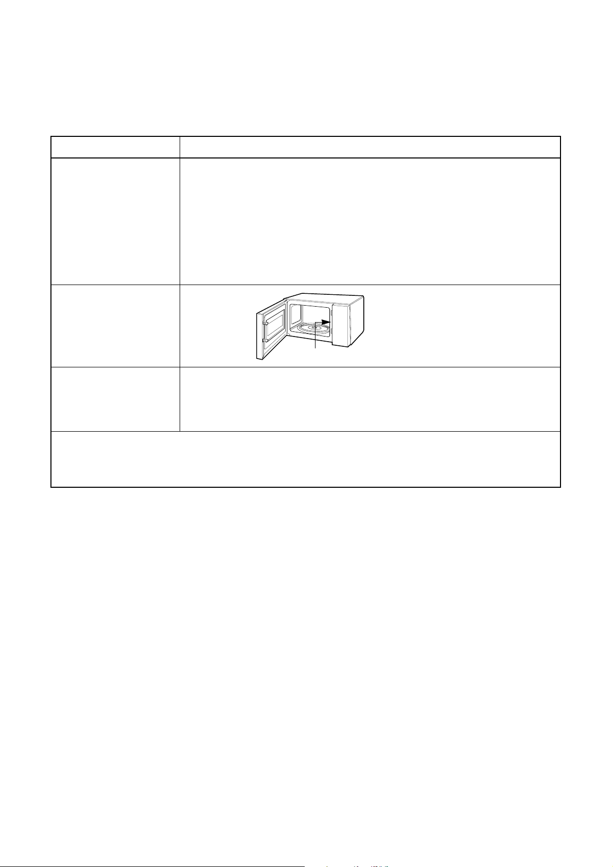
POWER LEVEL & ACCESSORIES
ITEM
Control Complement
Rating Label Location
Accessories
This microwave oven is designed for household use only.
Microwave Power for Variable Cooking
Power level
Max
Medium High
Medium
Medium Low
I
Low
Instruction manual
Glass Tray
Ro Rller ing
900 Watts
720 Watts
540 Watts
270 Watts
90 Watts
Inside
DESCRIPTION
It is not recommended for commercial purposes.
1-1
Page 5
• DO NOT operate on a 2-wire extension cord during
repair and use.
• NEVER TOUCH any oven components or wiring during
operation.
• BEFORE TOUCHING any parts of the oven, always
remove the power plug from the outlet.
• For about 30 seconds after the oven stops, an electric
charge remains in the high voltage capacitor. When
replacing or checking, you must discharge the high
voltage capacitor by shorting across the two terminals
with an insulated screwdriver.
•
Remove your watches whenever working close to or
replacing the Magnetron.
• NEVER operate the oven with no load.
• NEVER injure the door seal and front plate of the oven
cavity.
• NEVER put iron tools on the magnetron.
• NEVER put anything into the latch hole and the
interlock switches area.
• Proper operation of the microwave oven requires that
the magnetron be assembled to the waveguide and
cavity. Never operate the magnetron unless it is
properly installed.
• Be sure that the magnetron gasket is properly
installed around the dome of the tube whenever
installing the magnetron.
2-1
CAUTIONS
Unlike other appliances, the microwave oven is
high-voltage and high-current equipment.
Though it is free from danger in ordinary use,
extreme care should be taken during repair.
THE OVEN IS TO BE SERVICED ONLY
BY PROPERLY QUALIFIED SERVICE
PERSONNEL.
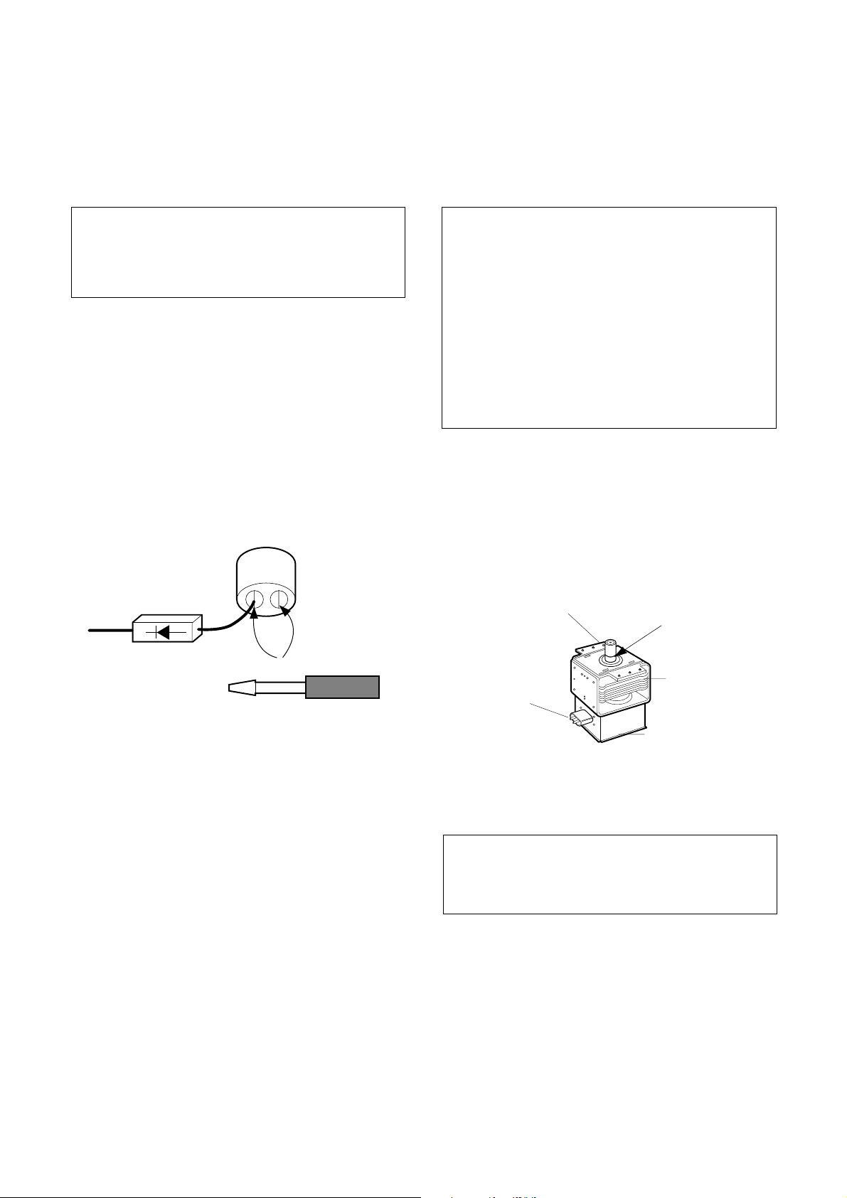
MICROWAVE RADIATION
Personnel should not be exposed to the
microwave energy which may radiate from the
magnetron or other microwave generating
device if it is improperly used or connection.
All input and output microwave connections,
waveguide, flange and gasket must be secure
never operate the device without a microwave
energy absorbing load attached.
Never look into an open waveguide or antenna
while the device is energized.
ANTENNA
COOLING FIN
MAGNETRON
CHASSIS GROUND
FILAMENT
TERMINALS
MAGNETRON
GASKET
Page 6
INSTALLATIONS
BEFORE YOU BEGIN, READ THE FOLLOWING INSTRUCTIONS COMPLETELY AND CAREFULLY.
INSTALLING
1. Empty the microwave oven and clean inside it with
a soft, damp cloth. Check for damage such as
misaligned door, damage around the door or dents
inside the cavity or on the exterior.
2. Put the oven on a counter, table, or shelf that is
strong enough to hold the oven and the food and
utensils you put in it. (The control panel side of the
oven is the heavy side. Use care when handling.)
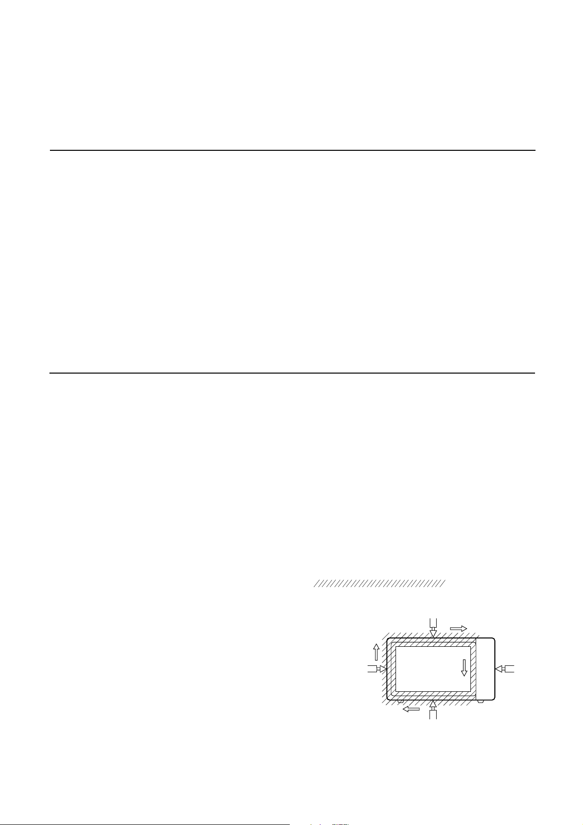
3. Do not block the vent and the air intake openings.
Blocking vent or air intake openings can cause
damage to the oven and poor cooking results.
Make sure the microwave oven legs are in place to
ensure proper air flow.
4. The oven should not be installed in any area where
heat and steam are generated, because they may
damage the electronic or mechanical parts of the
unit.
Do not install the oven next to a conventional
surface unit or above a conventional wall oven.
5. Use microwave oven in an ambient temperature
less than 104°F(40°C).
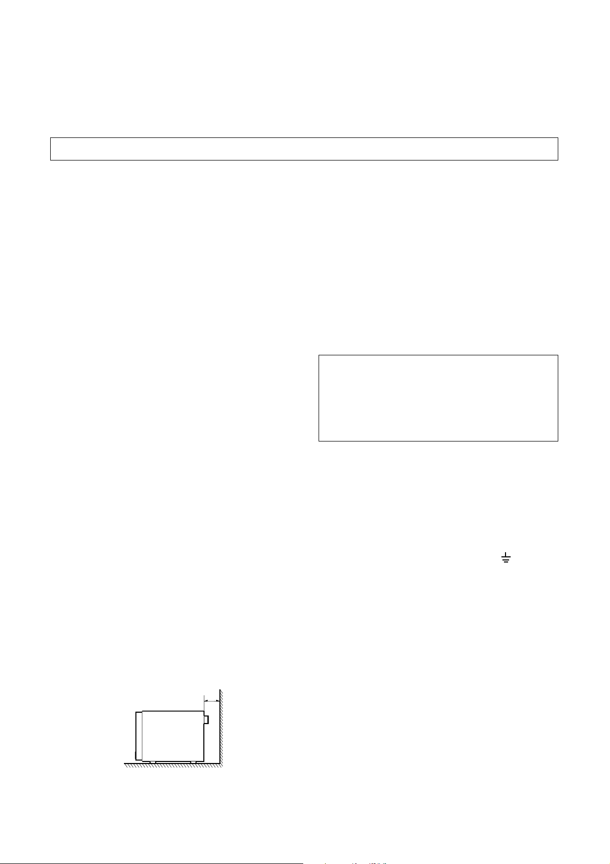
6. Place the microwave oven on a sturdy and flat
surface at least 10 cm(4 inches) from the wall.
7. Place the microwave oven as far away as possible
from TV, RADIO, COMPUTER, etc., to prevent
interference.
EARTHING INSTRUCTIONS
This microwave oven is designed to be used in a fully
earthed condition.
It is imperative, therefore, to make sure it is properly
earthed before servicing
WARNINGTHIS APPLIANCE
MUST BE EARTHED
IMPORTANT
The wires in this mains lead are colored in
accordance with the following code:
Green-and-yellow: Earth
Blue: Neutral
Brown: Live
As the colors of the wires in the mains lead of this
appliance may not correspond with the colored
markings identifying the terminals in your plug,
proceed as follows.
The wire which is colored green-and-yellow must be
connected to the terminal in the plug which is marked
with the letter E or by the earth symbol ( ) or
colored green or green-and-yellow.
10cm
The wire which is colored blue must be connected to
the terminal in the plug which is marked with the letter
N or colored black.
The wire which is colored brown must be connected
to the terminal in the plug which is marked with the
letter L or colored red.
3-1
Page 7
OPERATING INSTRUCTIONS
FEATURES
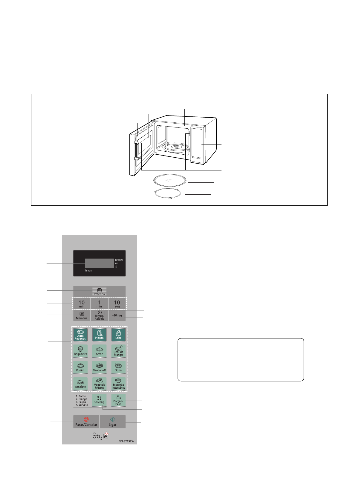
See-Through oven window
CONTROL PANEL
Door C
Oven Front Plate
Control Panel
Safety Door Lock System
Glass Tray
Roller Ring
(1)
(2)
(3)
(4)
(7)
(9)
(8)
(5)
(6)
-
NN-
ST652W
(1)
Display
(2)
Power Selection Tab
Number Tabs
(3)
Memory Tab
(4)
Timer / Clock Tab
(5)
+ 30 sec. Tab
(6)
Auto Cook Options
(7)
Defrost Tab
(8)
Serving / Weight Tab
(9)
Stop / Cancel Tab
(10)
Before Cooking:
During Cooking:
process. Another tap cancels
Start Tab
(11)
One tap begins oven
Beep Sound:
When a pad is pressed correctly, a beep will be heard.
If a pad is pressed and no beep is heard, the unit did
not or cannot accept the instruction. The oven will beep
twice between
complete program, the oven will beep 5 times.
R
UN
one tap cancels
one tap
functioning.
programmed stages. At the end of any
ST652W
NN
/
the inserted instructions.
temporarily stops the cooking
cooking.
R
UK
(10)
(11)
4-1
Page 8
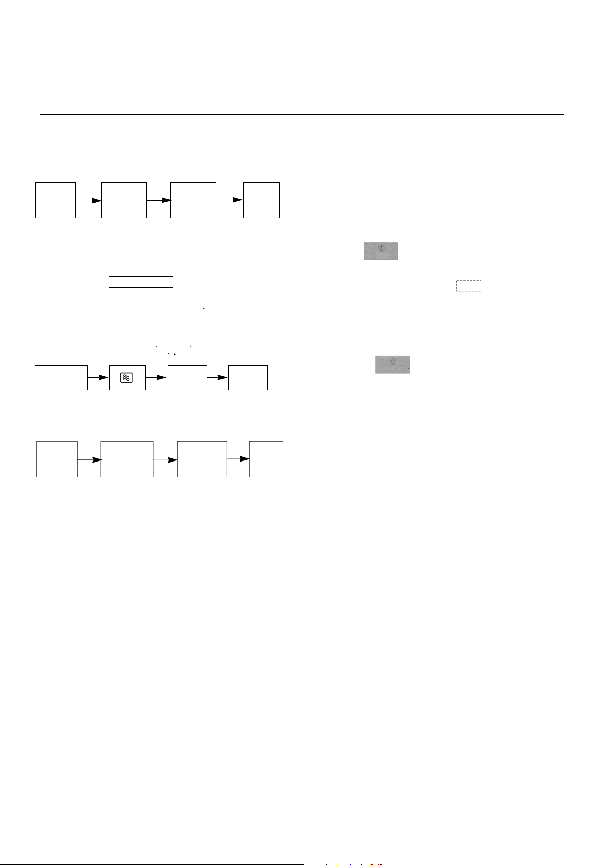
OPERATING SEQUENCE
The following is a description of component functions
during oven operation.
1. SETTING THE CLOCK
Stop/
Cancel
NOTE: This is a 12 hour clock.
Clock
Set the time
by pressing
time pads
Clock
2. CANCEL FUNCTION
Touch the S /Cancel pad whenever you need to
cancel an entry or a function currently in use.
The display will either return to the last item entered
or to the clock.
top
3. MICROWAVE COOKING
Stop/Cancel
TIME START
4. AUTO DEFROST COOKING
Stop/
Cancel
Desired
defrost
program
Desired
weight
Start
5. CHILD SAFETY LOCK
Using this system will make the oven inoperable; however,
the door can be opened.Child Lock can be set when the
display shows a colon or the time.
TO Set
Start
Press Start Pad 3 consecutive times.
The display will the indication on the word LOCK.
It indicates no programming will be accepted.
To Cancel
Stop/ Cancel
Press Stop/ Pad 3 consecutive times.
The colon or the time will be displayed again on the display.
In case of plug disconnection or energy shortage,the
lock will be automatically canceled.
Reset
4-2
Page 9
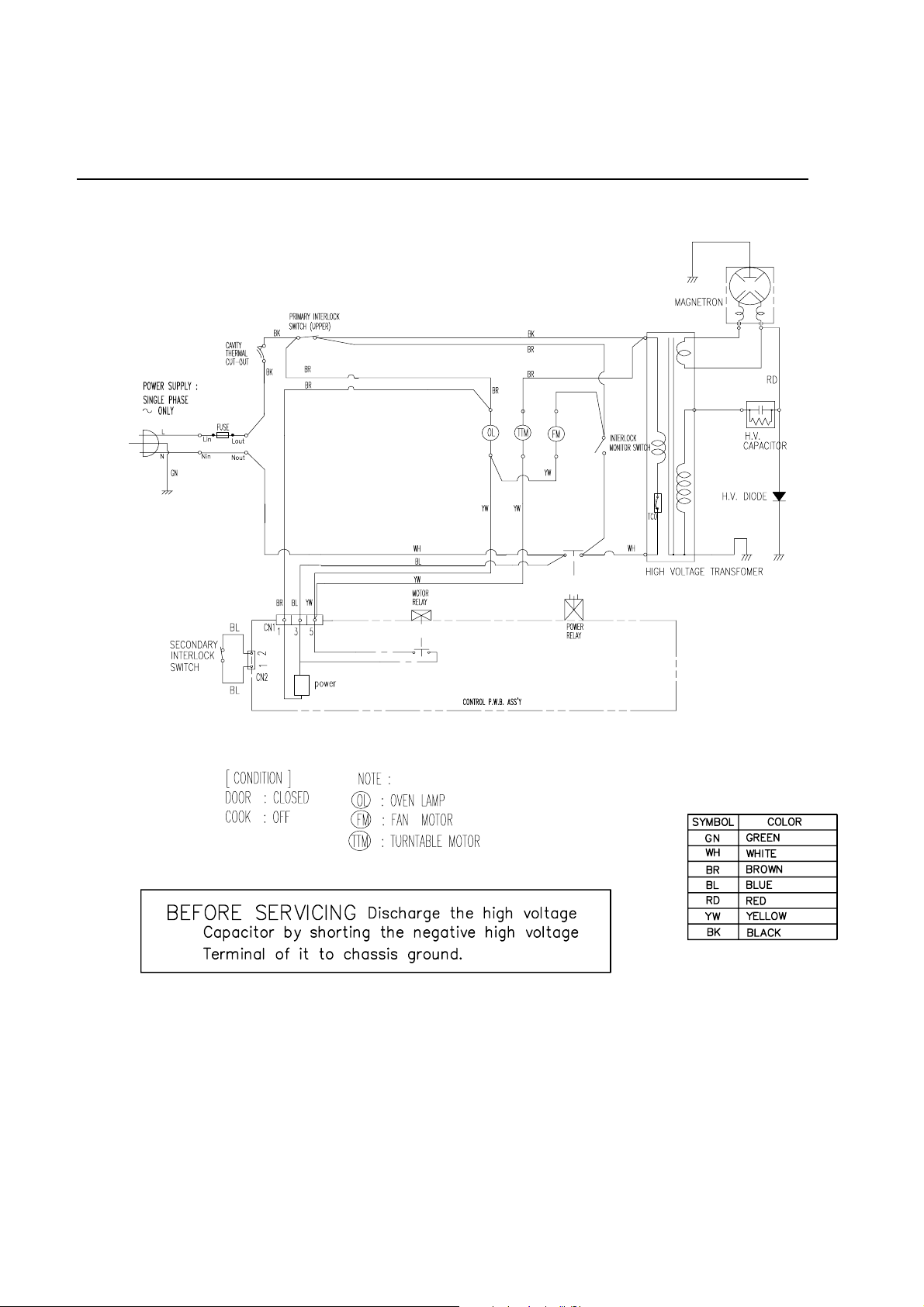
SCHEMATIC DIAGRAM
4-3
Page 10
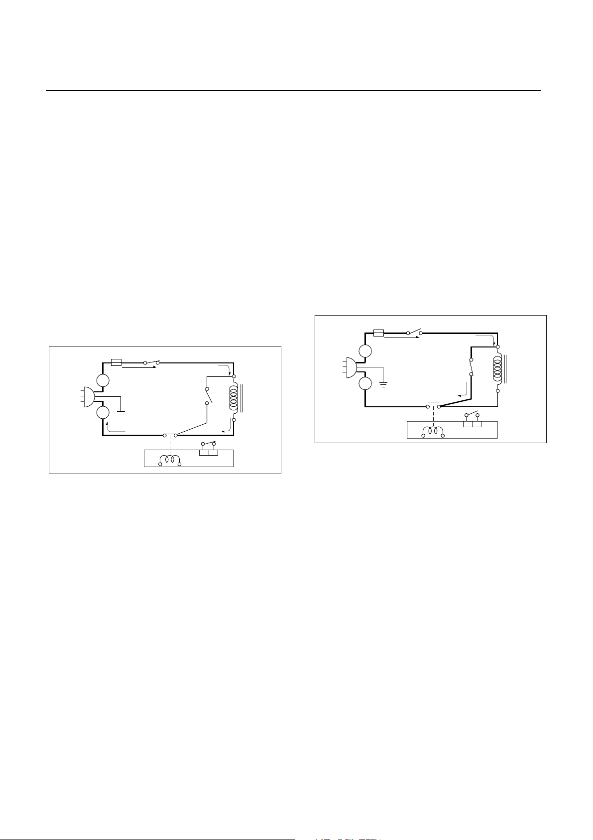
CIRCUIT DESCRIPTION
GENERAL DETAILS
• The low voltage transformer supplies the necessary
voltage to the micom controller when power cord is
plugged in.
• When the door is closed, the primary switch is ON, the
secondary switch is ON, and the monitor switch opens
(contact COM and NO).
WHEN SELECTING COOKING POWER
LEVEL AND TIME
• The micom controller memorizes the function you set.
• The time you set appears in the display window.
• Each indicator light turns on to indicate that the stage
has been set.
WHEN TOUCHING THE START PAD
• The coil of the relay is energized by the micom
controller.
• Power input is supplied to the high voltage transformer
through the fuse to the primary switch and relay 2.
• Turntable rotates.
FUSE
L
N
MICOM CONTROLLER
PRIMARY
SWITCH
RELAY 2
MONITOR
SWITCH
TRANS-
FORMER
SECONDARY
SWITCH
power of microwave oven as POWER LEVEL.
(refer to page 1-1)
WHEN THE DOOR IS OPENED DURING
COOKING
• Both the primary switch and relay 2 are cut off primary
winding voltage of the high voltage transformer.
• ON-OFF of relay 2 is coupled electrically with opening
and closing of the secondary switch.
• When the door is opened, the secondary switch is
opened and when the door is closed, the secondary
switch is closed.
• The cooking time stops counting down.
• Relay stops functioning.
• As the door is opened, if the contact of primary switch
and relay 2 and/or secondary switch fails to open, the
fuse opens due to the large current surge caused by
the monitor switch activation, which in turn stops
magnetron oscillation.
FUSE
L
N
MICOM CONTROLLER
PRIMARY
SWITCH
RELAY 2
MONITOR
SWITCH
FORMER
SECONDARY
SWITCH
• The fan motor rotates and cools the magnetron by
blowing the air (coming from the intake on the
backplate).
• The air is also directed into the oven to exhaust the
vapor in the oven through the left side.
• Cooking time starts counting down.
• 3.2 volts AC is generated from the filament winding of
the high voltage transformer. This 3.2 volts is applied to
the magnetron to heat the magnetron filament through
two noise-preventing choke coils.
• A high voltage of approximately 2100 volts AC is
generated in the secondary of the high voltage
transformer which is increased by the action of the high
voltage diode and charging of the high voltage
capacitor.
• The negative 4000 Volts DC is applied to the filament
of the magnetron.
WHEN THE OVEN IS SET AT ANY LEVEL
EXCEPT MAXIMUM.
• The micom controller controls the ON-OFF time of relay
2 by the applied signal to vary the average output
4-4
Page 11
CAUTIONS
• Be sure to check microwave leakage prior to
servicing the oven if the oven is operative prior to
servicing.
• The service personnel should inform the
manufacture importer, or assembler of any
certified oven unit found to have a microwave
emission level in excess of 5 mW/cm
2
and should
repair any unit found to have excessive emission levels
at no cost to the owner and should ascertain the cause
of the excessive leakage. The service personnel
should instruct the owner not to use the unit until the
oven has been brought into compliance.
• If the oven operates with the door open, the service
personnel should:
- Tell the user not to operate the oven.
- Contact the manufacturer.
• The service personnel should check all surface and
vent openings for microwave leakage.
• Check for microwave leakage after every servicing.
The power density of the microwave radiation leakage
emitted by the microwave oven should not exceed
4 mW/cm
2
. Always start measuring of an unknown field
to assure safety for operating personnel from radiation
leakage.
MEASURING MICROWAVE ENERGY
LEAKAGE
• Pour 275±15cc of 20±5°C(68±9°F) water in a beaker
which is graduated to 600 cc, and place the beaker
on the center of the turntable.
• Set the energy leakage monitor to 2450 MHz and
use it following the manufacturer's recommended
test procedure to assure correct result.
• When measuring the leakage, always use the 2inch (5cm) spacer supplied with the probe.
• Operate the oven at its maximum output.
• Measure the microwave radiation using and
electromagnetic radiation monitor by holding the
probe perpendicular to the surface being measured
Move probe along shaded area
Probe scanning speed
Less than 2.5 cm/sec
( 1in/sec)
5-1
SERVICE INFORMATION
TOOLS AND MEASURING INSTRUMENTS
MICROWAVE LEAKAGE TEST
NECESSARY TOOLS
Tools normally used for TV servicing are sufficient.
Standard tools are listed below.
• Diagonal pliers
• Long nose pliers
• Phillips screwdriver
• Flat blade screwdriver
• Wrench (size 5mm)
• Nutdriver (size 5mm)
• Adjustable wrench
• Soldering iron
• Solder
• Vinyl insulation tape
• Polishing cloth
NECESSARY MEASURING INSTRUMENTS
• TESTER(VOLTS-DC, AC., Ohmmeter)
• Microwave survey meter
- Holaday HI-1500
HI-1501
- Narda 8100
8200
• Inch scale
• 600 cc non conductive material beaker (glass or plastic),
inside diameter: approx. 8.5 cm(3
1
/2
in.)
• Cylindrical and made of borosilicate glass vessel.
max. thickness: 3 mm
outside diameter: approx. 190mm
height: approx. 90mm
• Glass thermometer: 100°C or 212°F (1 deg scale)
Page 12
MEASUREMENT WITH OUTER CASE
REMOVED
• When you replace the magnetron, measure for
microwave energy leakage before the outer case is
installed and after all necessary components are
replaced or adjusted.
Special care should be taken in measuring the
following parts. (Circled area of below Fig.)
- Around the magnetron
- The waveguide
WARNING : AVOID CONTACTING ANY
HIGH VOLTAGE PARTS
NOTES WHEN MEASURING
• Do not exceed meter full scale deflection.
• The test probe must be removed no faster than
1 inch/sec (2.5 cm/sec) along the shaded area,
otherwise a false reading may result.
• The test probe must be held with the grip portion of the
handle.
A false reading may result if the operator's hand is
between the handle and the probe.
• When testing near a corner of the door, keep the probe
perpendicular to the surface making sure the probe
horizontally along the oven surface, this may possibly
cause probe damage.
RECORD KEEPING AND NOTIFICATION
AFTER MEASUREMENT
• After adjustment and repair of any microwave energy
interruption or microwave energy blocking device,
record the measured values for future reference. Also
enter the information on the service invoice.
• The microwave energy leakage should not be more
than 4 mW/cm2.sq. after determining that all parts are
in good condition, functioning properly and genuine
replacement parts which are listed in this manual have
been used.
• At least once a year, have the electromagnetic energy
leakage monitor checked for calibration by its
manufacturer.
MEASUREMENT WITH A FULLY
ASSEMBLED OVEN
• After all components, including the outer case, are fully
assembled, measure for microwave energy leakage
around the door viewing window, the exhaust opening,
and air inlet openings.
• Microwave energy leakage must not exceed the values
prescribed below.
NOTE: Leakage with the outer case removedless than
5 mW/cm2.sq. Leakage for a fully assembled
oven (Before the latch switch (primary) is
interrupted) with the door in a slightly opened
position-less than 2 mW/cm2.sq.
5-2
Page 13

MEASUREMENT OF MICROWAVE POWER OUTPUT
WATER LOAD
TURNTABLE
• Microwave power output measurement is made with
the microwave oven supplied at its rated voltage and
operated at its maximum microwave power setting with
a load of (1000±5) g of potable water.
• The water is contained in a cylindrical borosilicate glass
vessel having a maximum material thickness of 3 mm
and an outside diameter of approximately 190mm.
• The oven and the empty vessel are at ambient
temperature prior to the start of the test.
• The initial temperature (T1) of the water is (10±2)°C. It
is measured immediately before the water is added to
the vessel. After addition of the water to the vessel,
the load is immediately placed on the center of the
turntable which is in thd lowest position and the
microwave power switched on.
• The time T for the temperature of the water to rise by a
value ∆ T of (10±2)°K is measured, where T is the time
in seconds and ∆T is the temperature rise. The initial
and final water temperatures are selected so that the
maximum difference between the final water
temperature and the ambient temperature is 5°K.
• The microwave power output P in watts is calculated
from the following formula :
4187 x (∆T) + 0.55 X (T
P =
2
- T0) X M
T
• T2: Temperature after heating
• T
0
: Temperature of bowl
• M: Weight of bowl
is measured while the microwave generator is
operating at full power. Magnetron filament heat-up
time is not included. (about 3 sec)
• The water is stirred to equalize temperature throughout
the vessel, prior to measuring the final water
temperature.
• Stirring devices and measuring instruments are
selected in order to minimize addition or removal of
heat.
NOTES:
For simple tests of micromave power output,
it by heating one litre water for one minute,
minimum temperature rise should be 6 C
conduct
°
DISASSEMBLY AND ADJUSTMENT
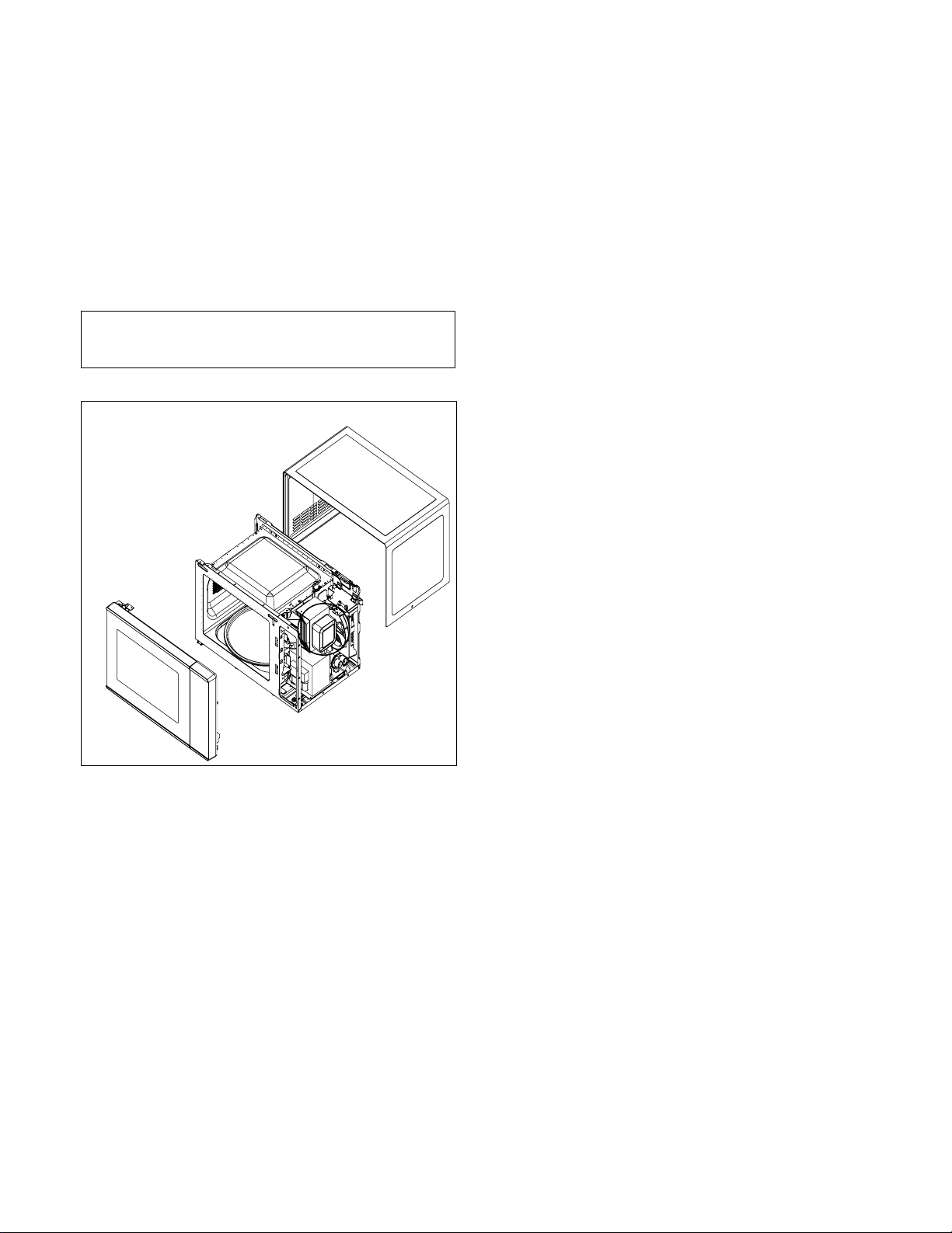
A. OUTER CASE REMOVAL
1) Disconnect the power supply cord from the outlet.
2) Remove the screws from the rear and along side
edges of the case.
The outer case must be moved backward to be lifted
off.
B. POWER SUPPLY CORD
1) Remove the outer case.
2) Disconnect two terminals, and remove one screw of
the earth terminal.
CAUTION: DISCHARGE THE HIGH VOLTAGE
CAPACITOR BEFORE SERVICING
(refer to page 2-1)
C. CONTROL PANEL ASSEMBLY
1) Disconnect the leadwire from the Timer motor
2) Remove the screws for securing the control panel.
3) Lift control panel ASS ’Y from the oven by the tab
unhooked.
5-3
Page 14
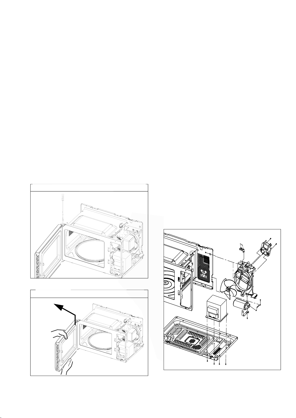
D. DOOR ASSEMBLY REMOVAL
1) Open the door.
2) Remove two screws holding the Hinge
to the Cavity Ass'y.
CAUTION : Be careful not to damage Door C
by screwdriver.
3) Lift up and pull the door.
E. HIGH VOLTAGE TRANSFORMER
REMOVAL
1) Discharge the high voltage capacitor.
2) Disconnect the leadwire from magnetron, high voltage
transformer, and capacitor.
3) Remove the screw holding the high voltage
transformer to the baseplate.
NOTE:
1. After replacing the door, be sure to check that the
primary switch, monitor switch, and secondary switch
operate normally.
2. After replacing the door, check for microwave energy
leakage with a survey meter. Microwave energy must
be below the limit of 5 mW/cm
load)
3. When mounting the door assembly to the oven
assembly, be sure to adjust the door assembly parallel
to the chassis. Also adjust so the door has no play
between the inner door surface and oven frame
assembly. If the door assembly is not mounted
properly, microwaves may leak from the clearance
between the door and the oven.
Remove door Assembly
2
. (with a 275 ml water
F.
ORIFICE
1) Discharge the high voltage capacitor.
2) Disconnect the leadwire from fan motor, noise filter
and high voltage capacitor.
3) Remove the two screws holding the orifice
to the
earth screw.
4) Remove the screw of the capacitor bracket.
5) Remove the two screws holding the fan motor ASS’Y
to the Orifice
ASSEMBLY REMOVAL
oven cavity and remove the high
.
ASS’Y
ASS’Y
voltage
diode
G. HIGH VOLTAGE CAPACITOR AND
DIODE REMOVAL
1) Discharge the high voltage capacitor.
2) Disconnect the leadwire from fan motor, noise filter
and high voltage capacitor.
3) Remove the screw holding the Orifice
the oven
earth screw.
4) Remove the screw holding the high voltage capacitor
bracket.
cavity and remove the high voltage diode
ASS’Y
to
Remove door Assembly
5-4
Page 15

H. AIR GUIDE ASSEMBLY REMOVAL
1) Disconnect the leadwire from lamp, A.C Relay and
monitor resistor and magnetron.
2) Remove the screw to the cavity.
I. MAGNETRON REMOVAL
1) Disconnect the leadwire from the high voltage
transformer and high voltage capacitor.
2) Remove the air guide.
3) Carefully remove the mounting screws holding the
magnetron and the waveguide.
4) Remove the magnetron until the tube is
clear from the waveguide.
NOTE:
1. When removing the magnetron, make sure its
dome does not hit any adjacent parts, or it may be
damaged.
2. When replacing the magnetron, be sure to install
the magnetron gasket in the correct position and
be sure that the gasket is in good condition.
3. After replacing the magnetron, check for microwave
leakage with a survey meter around the
magnetron. Microwave energy must be below the
limit of 5 mW/cm
Make sure that gasket is rigidly attached to the
magnetron.
mounting screws properly, making sure there is no gap
between the waveguide and the magnetron.
2
. (With a 275 ml. water load).
To prevent microwave leakage, tighten the
J. REMOVING THE TURNTABLE MOTOR
1) Remove the .
2) Remove the pully shaft VERY CAREFULLY
3) Lay the unit down on its back.
4) Remove the turntable motor cover.
The turntable base cover is easily removed by
pinching the six parts with a wire cutting.
5) Disconnect the leadwire from the turntable motor
terminals.
6) Remove the screw securing the turntable motor to
the oven cavity ASS’Y
7) After rep the motor, rotate the removed
turntable motor cover.
8) Fit the turntable motor cover’s projecting part to the
base plate slit.
NOTE:
1. Remove the wire lead from the turntable motor
VERY CAREFULLY.
2. Be sure to grasp the connector, not the wires, when
removing
glass tray
lacing
Magnetron
Magnetron
Gasket
Waveguide
Bracket
Dome
Waveguide
Base plate
Magnetron
5-5
Page 16

K. PCB ASSEMBLY REMOVAL
1) Remove the control panel assembly from the
cavity.
2) Remove screws which hold the PCB to
control panel.
3) Disconnect the flat cable from the PCB
take off the PCB .
C
17
the
and
L. INTERLOCK SYSTEM
1) INTERLOCK MECHANISM
The door lock mechanism is a device which has
been specially designed to eliminate completely
microwave activity when the door is opened during
cooking and thus to prevent the danger resulting
from the microwave leakage.
2) MOUNTING OF THE PRIMARY/MONITOR/
SECONDARY SWITCHES TO THE LATCH
BOARD
ADJUSTMENT
DIRECTION
PRIMARY
SWITCH
MONITOR
SWITCH
SECONDARY
SWITCH
3) INSTALLATION AND ADJUSTMENT OF THE
LATCH BOARD TO THE OVEN ASSEMBLY
• Mount the latch board to the oven assembly.
• Adjust the latch board in the arrow direction so that
oven door will not have any play in it when the door
is closed.
• Tighten the mounting screw.
• Check for play in the door by pushing the door
release button. Door movement should be less
than 0.5 mm. (1/64 inch)
Don't push the door release button while making
adjustment. Make sure that the latch moves
smoothly after adjustment are completed and that
the screws are tight. Make sure the primary, monitor,
and secondary switches operate properly by
following the continuity test procedure.
FIG. 1
CAUTION: CHECK THE CORRECT POSITION
MAGNETRON
H.V. TRANSFORMER
H.V. CAPACITOR
PRIMARY
H.V.
DIODE
5-6
Page 17
A. PRIMARY INTERLOCK SWITCH TEST
When the door release button is depressed slowly
with the door closed, an audible click should be
heard at the same time or successively at
intervals. When the button is released slowly, the
latches should activate the switches with an
audible click.
If the latches do not activate the switches when
the door is closed, the switches should be a
adjusted in accordance with the adjustment
procedure. Disconnect the wire lead from the
primary switch. Connect the ohmmeter leads to
the common (COM) and normally open (NO)
terminal of the switch. The meter should indicate
an open circuit in the door open condition.
When the door is closed, the meter should
indicate a closed circuit.
When the primary switch operation is abnormal,
make the necessary adjustment or replace the
switch only with the same type of switch.
B. SECONDARY INTERLOCK SWITCH TEST
Disconnect the wire lead from the secondary
switch.
Connect the ohmmeter leads to the common
(COM) and normally open (NO) terminals of the
switch. The meter should indicate a open circuit in
the door open condition. When the door is closed,
meter should indicate an closed circuit. When the
secondary switch operation is abnormal, make the
necessary adjustment or replace the switch only
with the same type of switch.
C. MONITOR SWITCH TEST
Disconnect the wire lead from the monitor switch.
Connect the ohmmeter leads to the common
(COM) and normally closed (NC) terminals of the
switch. The meter should indicate closed circuit in
the door open condition. When the door is closed,
meter should indicate an open circuit. When the
monitor switch operation is abnormal, replace with
the same type of switch.
NOTE: After repairing the door or the interlock
system, it is necessary to do this continuity
test before operating the oven.
5-7
WARNING : FOR CONTINUED PROTECTION AGAINST EXCESSIVE RADIATION
EMISSION, REPLACE ONLY WITH IDENTICAL REPLACEMENT PARTS.
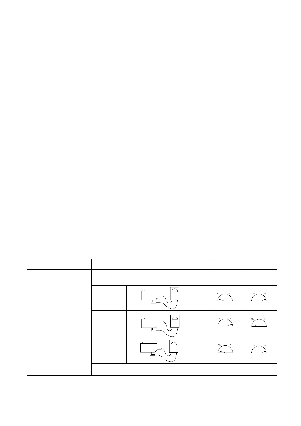
COMPONENTS TEST PROCEDURE RESULTS
SWITCHES Check for continuity of the Door Door
(Wire leads removed) switch with an Ohm-meter open closed
Primary
Switch
Monitor
Switch
NOTE : After checking for the continuity of switches, make sure that are
correctly connected.
INTERLOCK CONTINUITY TEST
Secondary
Switch
TYPE NO. KW3A FOR SWITCHS
Type No.KW3A
Type No.KW3A
Type No.KW3A
COM
COM
NO
NC
COM
NO
Page 18

COMPONENT TEST PROCEDURE
CAUTIONS
1. DISCONNECT THE POWER SUPPLY CORD FROM THE OUTLET WHENEVER REMOVING THE
OUTER CASE FROM THE UNIT. PROCEED WITH THE TEST ONLY AFTER DISCHARGING THE HIGH
VOLTAGE CAPACITOR AND REMOVING THE WIRE LEADS FROM THE PRIMARY WINDING OF THE
HIGH VOLTAGE TRANSFORMER. (SEE PAGE 2-1)
2. ALL OPERATIONAL CHECKS WITH MICROWAVE ENERGY MUST BE DONE WITH A LOAD (1 LITER
OF WATER IN CONTAINER) IN THE OVEN.
COMPONENTS TEST PROCEDURE RESULTS
HIGH VOLTAGE
TRANSFORMER
(Wire leads removed)
FILAMENT
WINDING
TERMINAL
MAGNETRON
(Wire leads removed)
PRIMARY
TERMINAL
1. Measure the resistance.
(Ohm-meter scale: Rx1)
• Primary winding
• Secondary winding
• Filament winding
2. Measure the resistance.
(Ohm-meter scale: Rx1000)
• Primary winding to ground
• Filament winding to ground
1. Measure the resistance.
(Ohm-meter scale: Rx1)
• Filament terminal
2. Measure the resistance.
(Ohm-meter scale: Rx1000)
• Filament to chassis
SECONDARY
WINDING
Approx.: 1.4 ohm
Approx.: 90 ohm
Less than: 1 ohm
Normal: Infinite
Normal: Infinite
Normal: Less than 1 ohm
Normal: Infinite
5-8
Page 19

COMPONENTS TEST PROCEDURE RESULTS
Antenna
Gasket
Chassis
Filament
NOTE: When testing the magnetron, be sure to install the magnetron gasket
in the correct position and be sure that the gasket is in good condition.
HIGH VOLTAGE
CAPACITOR
HIGH VOLTAGE
DIODE
Measure the resistance.
(Ohm-meter scale: Rx1000)
• Terminal to terminal.
Measure the resistance.
(Ohm-meter scale: Rx1000)
• Terminal to case.
Measure the continuity (Forward).
(Ohm-meter scale: Rx10000)
Normal: Momentarily indicates
several ohms, and then
gradually returns to
10M ohms.
Normal: ∞
Normal: Continuity.
Abnormal: ∞
*
NOTE :
*
Some inexpensive meters
may indicate infinite
resistance in both direction.
Measure the continuity (Reverse).
(Ohm-meter scale: Rx10000)
5-9
Normal: ∞
Abnormal: Continuity.
Page 20

COMPONENTS TEST PROCEDURE RESULTS
FUSE
THERMAL
CUT-OUT
L.V.Transformer of P.C.B
(Refer to schemetic diagram)
Check for continuity of the fuse with an
multi-meter.
NOTE: If the fuse is blown, check the primary, the secondary, and the monitor switches,
H.V.D. and H.V.C. before replacing the fuse.
If the fuse is blown by improper switch operation replace the defective switch and the
fuse at the same time. Replace just the fuse if the switches operate normally.
Check for P.C.B. connector.
Disconnect the 3 pin
*
Normal Abnormal
Below specified
temperature
Normal
Above
temperature
Abnormal
specified
connector from P.C.B.
RELAY 2, RELAY 3
OF P.C.B.
(Wire leads removed.)
Note: Relay
Relay 1: Fan motor
Turntable motor
Oven lamp
Relay 2: Microwave
135
Cooking Start OFF
Relay 1
Relay 2
5-10
Page 21

COMPONENTS TEST PROCEDURE RESULTS
FAN MOTOR
(Wire leads removed)
TURNTABLE
MOTOR
(Wire leads removed)
Measure the resistance.
(Ohm-meter scale: R x 100)
Measure the resistance.
(Ohm-meter scale: R x 1000)
Normal:
Abnormal: ∞ or several Ω
Normal: Approx.100~200K
Abnormal: ∞ or several
00~5001
Ω
Ω
Ω
NOTE : • A MICROWAVE LEAKAGE TEST MUST ALWAYS BE PERFORMED WHEN THE UNIT IS
SERVICED FOR ANY REASON.
• MAKE SURE THE WIRE LEADS ARE IN THE CORRECT POSITION.
• WHEN REMOVING THE WIRE LEADS FROM THE PARTS, BE SURE TO GRASP THE
CONNECTOR, NOT THE WIRES.
5-11
Page 22
5-12
TROUBLE SHOOTING
WHEN YOU GET A COMPLAINT FROM YOUR CUSTOMER, EVALUATE THE COMPLAINT CAREFULLY. IF
THE FOLLOWING SYMPTOMS APPLY, PLEASE INSTRUCT THE CUSTOMER IN THE PROPER USE OF THE
MICROWAVE OVEN. THIS CAN ELIMINATE AN UNNECESSARY SERVICE CALL.
CAUTIONS
1. Check grounding before checking for trouble.
2. Be careful of the high voltage circuit.
3. Discharge the high voltage capacitor. (See page 2-1)
4. When checking the continuity of the switches or of the high voltage transformer, disconnect one lead wire
from these parts and then check continuity with the AC plug removed. To do otherwise may result in a
false reading or damage to your meter.
5. Do not touch any part of the circuitry on the digital programmer circuit since static electric discharge may
damage this control panel.
Always touch yourself ground while working on this panel to discharge any static charge built up in your
body.
CONDITION
Microwave oven
does not work.
Output power is too low. Low AC input voltage.
Sparks occurring.
Inserting many plug into one
plug outlet and using
them at the same time
(causes overloading).
Microwave oven plug is not
inserted tightly.
Food temperature is too low.
Using metallic ware and
allowing it to touch the oven
wall.
Ceramic ware trimmed in
gold or silver powder is used.
CAUSE REMEDY
Avoid using other electrical
appliances when you use the
microwave oven.
Insert microwave oven plug
securely.
Use the microwave oven at
adequate line voltage.
This may not be a defect.
It is possible that the food
should be cooked for a
longer time period.
Do not use metallic ware for
cooking except where noted
in the cooking guide.
Do not use any type of
cookware with metallic
trimming.
Uneven cooking.
Turntable drags or makes
noise.
Inconsistent intensity of
microwave by their
characteristics.
Excessive weight on tray or
improperly balanced.
1. Wrap the thinner part with
aluminum foil.
2. Use plastic wrap or lid.
3. Stir once or twice while cooking
soup, cocoa or milk, etc.
Distribute food evenly. Cook
smaller portions and,or use
lighter weight cookware.
Page 23

(TROUBLE 1)
1. Incomplete segments.
• Segment missing.
• Partial segment missing.
• Digit flickering (NOTE: Slight flickering is normal.)
2. Colon does not turn on or blink.
3. A distinct change in the brightness of one or more numbers in display.
4. One or more digits in the display are not lighting.
5. Display indicates a number different from one touched, for example, key in 5 and 3 appears in the display.
6. Specific numbers (for example 7 or 9) will not display when key pad is touched.
7. Display does not count down with time blinking or up with clock operation.
8. Display obviously jumps in time while counting down.
9. Display counts down too fast while cooking.
10. Each indicator light does not turn on after setting cooking cycle.
11. Display time of day does not reappear when cooking is finished.
12. Beep sound is not heard when correct key is touched.
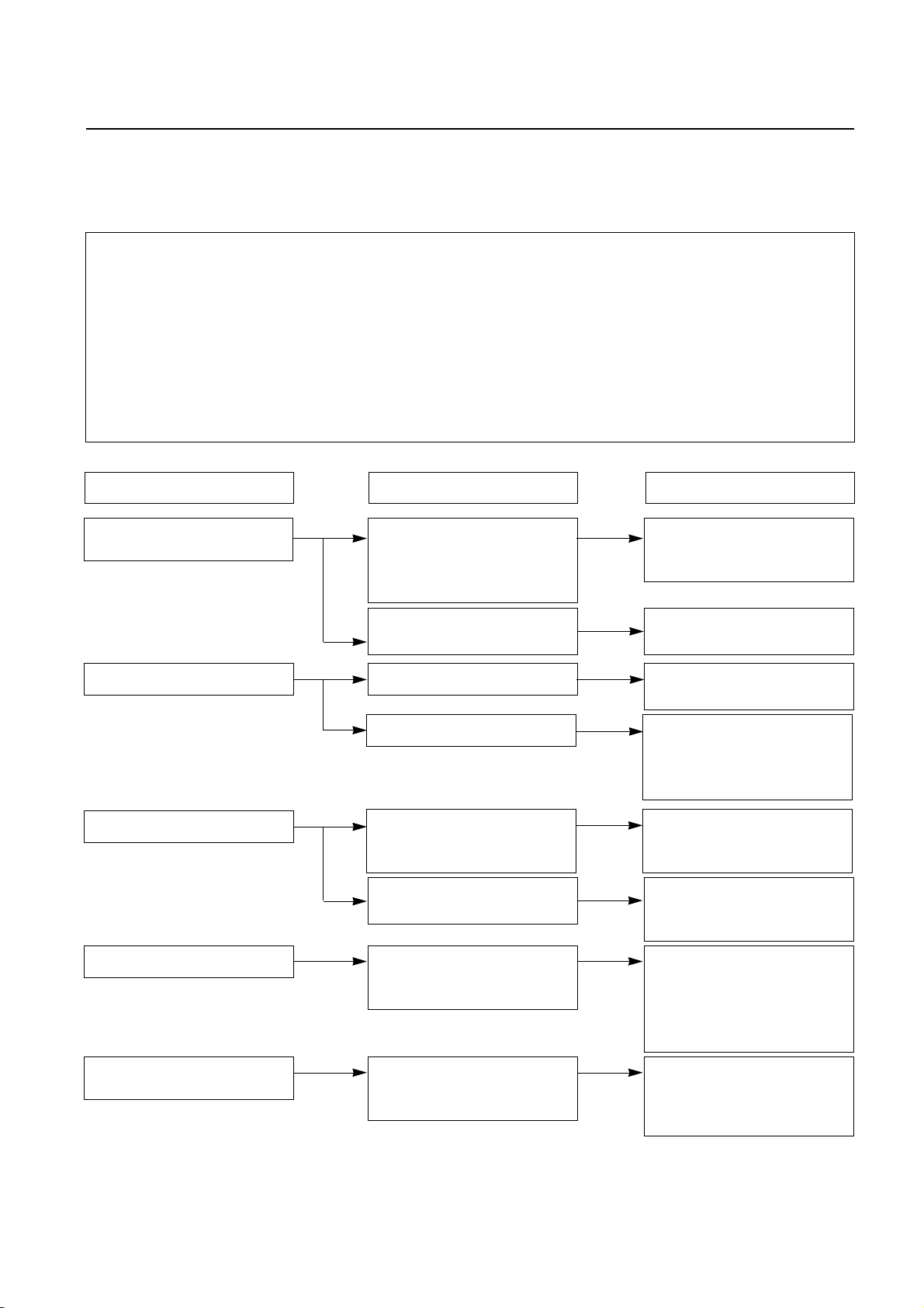
The following visual conditions indicate a probable defective control circuit.
CONDITION CHECK RESULT CAUSE REMEDY
1. No input can be
programmed.
2. Some inputs
cannot be
programmed.
3. Display shows a
number or figure
different from one
touched.
4. Random
programming
when touching
other pads.
5. Display is fixed
at some figure
and can not
accept any
input.
Check the connection between
membrane key
assembly and
PCB assembly.
Replace key
membrane
assembly and
check operation.
Continuity.
No continuity.
Everything works
as specified.
Still have
trouble.
Defective PCB
assembly.
Loose
connection.
Defective key
membrane
assembly.
Defective PCB
assembly.
Replace PCB
assembly.
Connect them
tightly.
Replace key
membrane
assembly.
Replace PCB
assembly.
5-13
Page 24

(TROUBLE 2)
Oven does not operate at all ; Display window does not display any figures and
no input is accepted.
CONDITION CHECK RESULT CAUSE REMEDY
1. Fuse blows. Continuity.
Check continuity
of monitor
switch (with
door closed).
Replace fuse
Check continuity
of primary
switch (with
door opened).
Disconnect one
side of the wire
lead connected
from transformer
to the high
voltage
capacitor and
operate the unit.
No continuity.
Continuity.
No continuity.
Normal.
Fuse blows again
Malfunction of the
monitor switch.
Shorted contact at
the primary switch.
Defective high
voltage capacitor.
Defective high voltage transformer.
Replace primary
and monitor
switches.
Replace primary
and monitor
switches.
Replace high
voltage capacitor.
Replace high voltage transformer.
NOTE : All these switches must be replaced at the same time. Refer to page 5-6, 5-7
2. Fuse does not
blow.
Check continuity
of magnetron
thermostat.
Check continuity
of power supply
cord.
No continuity.
Continuity.
No continuity.
Defective magnetron thermostat.
Defective power
supply cord.
5-14
Replace magnetron thermostat.
Replace power
supply cord.
Page 25
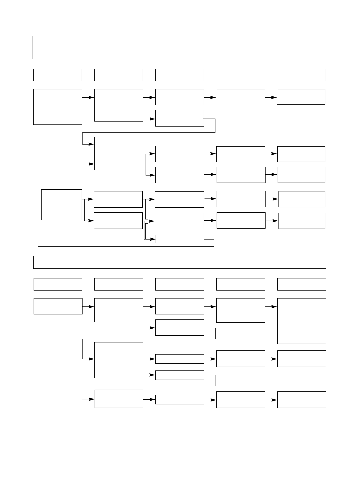
(TROUBLE 3) Display shows all figures set, but oven does not start cooking while
desired program times are set and START pad is touched.
CONDITION CHECK RESULT CAUSE REMEDY
1.Setting time does
not count down
when touching
START pad.
2. Fan motor or
oven lamp
do not turn
on.
Check continuity
of secondary
switch (with
door closed).
Check the connection between
connector and
P.C.B assembly.
Check fan motor.
Check oven lamp.
No continuity.
continuity.
No continuity.
Continuity.
Abnormal.
Abnormal.
Normal.
Defective
secondary switch.
Defective P.C.B
assembly.
Loose connection.
Defective fan
motor.
Defective oven
lamp.
(TROUBLE 4) Oven seems to be operation but output power is low.
Replace
secondary switch.
Replace P.C.B
assembly.
Connection then
tightly.
Replace fan
motor.
Replace oven
lamp.
CONDITION CHECK RESULT CAUSE REMEDY
Output is low.
NOTE: Refer to Page 5-3 for measuring of microwave power output.
Check the
power source
voltage.
Disconnect the
wire leads from
relay 2 and check
on and off time
with multitester.
Measure the
output power.
Lower than 90% of
rating voltage.
Normal.
Abnormal.
Normal.
Abnormal.
5-15
Decrease in power
source voltage
with load.
Defective P.C.B
assembly.
Defective
magnetron.
Suggest customer
contact local
electric power
utility co. or
qualified
electrician.
Replace P.C.B
assembly.
Replace
magnetron.
Page 26

5-16
CONDITION CHECK RESULT CAUSE REMEDY
No microwave
oscillation.
No continuity.
Continuity.
Defective P.C.B
assembly
Replace P.C.B
assembly
Disconnect the
wire leads from
relay 2 and
check continuity
of relay2.
(Operate the
unit)
Abnormal
normal
Defective high
voltage
transformer.
Replace high
voltage
transformer .
Check H.V.
transformer.
normal
normal
Abnormal
Defective high
voltage Diode.
Replace high
voltage Diode.
Check H.V.
diode.
Abnormal
Defective high
voltage capacitor.
Replace high
voltage capacitor.
Check H.V.
capacitor.
Abnormal
Defective
magnetron.
Replace
magnetron .
Check
Magnetron.
normal
Abnormal
Defective
Protector Diode.
Replace
Protector Diode .
Check
Protector Diode.
(TROUBLE 5)
No microwave oscillation even though oven lamp and fan motor run
(Display operates properly)
Page 27

5-17
(TROUBLE 6) Oven does not cook properly when programmed for the set power level
(Operates properly on HIGH)
CONDITION CHECK RESULT CAUSE REMEDY
Output is full when
you set lower
power level.
Abnormal.
Disconnect the
wire leads from
relay 2 and check
continuity relay 2.
(Operate the unit)
Defective P.C.B.
assembly.
Replace P.C.B.
assembly.
Page 28

INTRODUCTION
EXPLODED VIEW
DOOR PARTS
CONTROL PANEL PARTS
OVEN CAVITY PARTS
INTERIOR PARTS
BASE PLATE PARTS
LATCH BOARD PARTS
6-1
Page 29

DOOR PARTS
D
08
D
D
04
D
01
05
D
07
S03
D06
D
S05
D
14
D
03
02
6-2
Page 30

CONTROL PANEL PARTS
C
C
01
C
55
C
18
S03
C
05
C
17
6-3
Page 31

OVEN CAVITY PARTS
04
T
T
03
Z24
S07
D
05
A
A
00
01
T
02
T
01
S05
S03
S07
6-4
Page 32

LATCH BOARD PARTS
A
6-5
L
01
L
03
L
L
03
04
L
02
S05
S05
Page 33
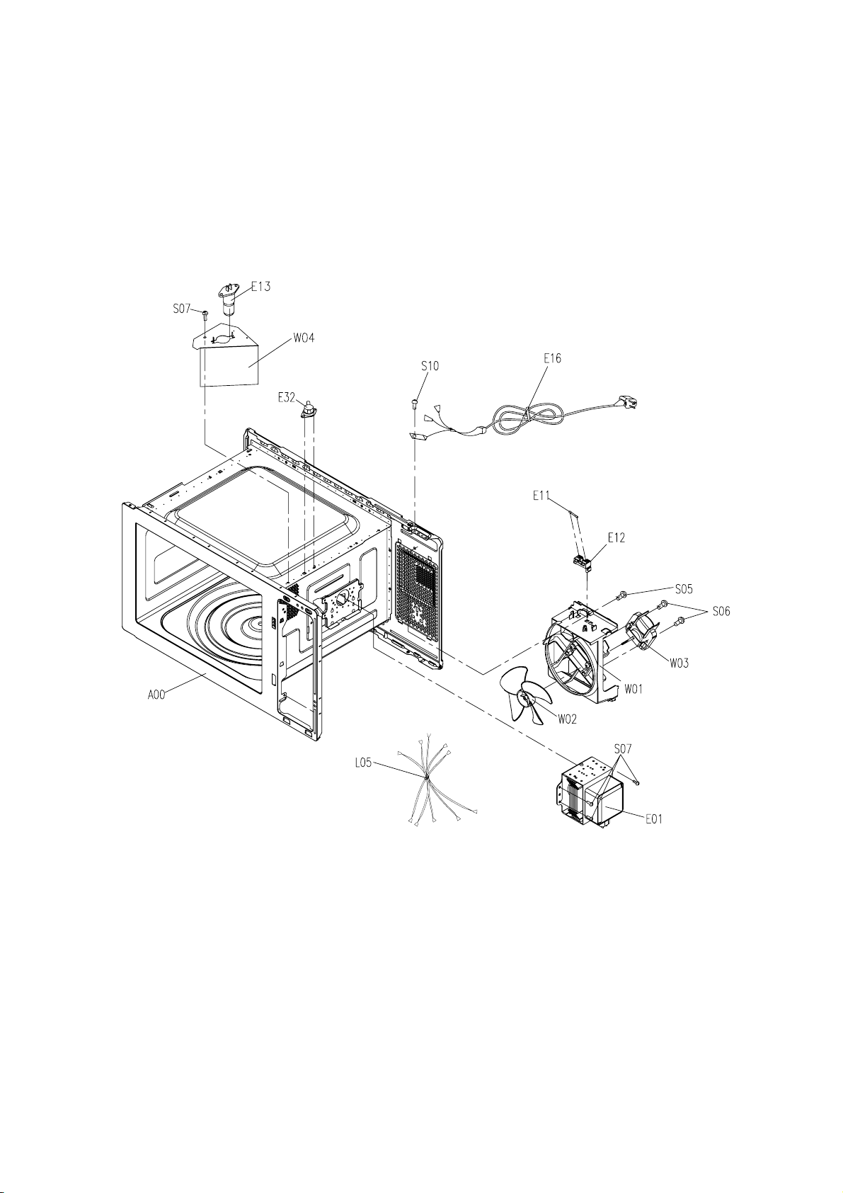
INTERIOR PARTS
E
13
S07
E
W
32
04
S10
E
E
11
16
E
12
A
00
L
05
S05
S05
S06
W
03
W
01
W
02
S07
E
01
6-6
Page 34

BASE PLATE PARTS
B
01
B
03
E
05
E
06
S07
Z01
E
07
S07
B
02
B
02
B
02
S07
Z22
S07
B
02
6-7
Page 35

REPLACEMENT PARTS LIST
D04
256502400556
TOP DOOR HINGE
1
)
NOTE:
1. When ordering replacement part(s), please use part number(s) shown in this part list.
Do not use description of the part.
2. Important safety notice:
Components identified by
When replacing any of these components, use only manufa cture’s specified parts.
For model:NN-ST652WRUN
Ref. No. Midea Part No. Part Name&Description Pcs/Set Remarks
A01 262100100003 CEILING COVER 1
B01 261501412406 BASE 1
B02 256302002770 RUBBER FOOT 4
B03 261502500200 LOWER HINGE 1
mark have special characteristics important for safety.
C01
!
261300268301 ESCUTCHEON BASE 1
C05 261820902853 ESCUTCHEON SHEET 1
C18 261400124990 PC BOARD(U) 1
C26 261400209450 MEMBRANE SWITCH 1
C55
!
261515903600 ESCUT.BACK PLATE 1
D01+D02+D
03+D04+D0
5+D06+D07
-263600205246 ASS'Y DOOR 1
+D08+D14
D01
!
251500200001 DOOR E 1
D02 251300500002 DOOR KEY A 1
D03 252010000000 DOOR KEY SPRING 1
D05
!
252200400301 DOOR SCREEN A 1
D06 262100403291 DOOR SCREEN B 1
D07
!
261300143000 DOOR A 1
287*180*0.1 (For
DOOR E
D08
D14 261300714800 HANDLE(U) 1
E01
E05
E06
E07
E11
!
!
!
!
!
!
251300600048 DOOR C 1
251200100068 MAGNETRON 1 2M219J
261200201731 H.V.TRANSFORMER 1
251200701306 H.V. CAPACITOR 1
251200900861 DIODE,SI 1
261201200040 FUSE 1
7 - 1
Page 36

REPLACEMENT PARTS LIST
)
)
For model:NN-ST652WRUN
E12 251201101569 HOLDER FUSE 1
E13 263600500001 LAMP(U) 1
E16
E45
L01+L02+L0
3+L04
L01
L02 261301101001 HOOK SPACER 1
L03
L04
L05 261202803431 LEAD WIRE HARNESS 1
T01 251200310976 TURNTABLE MOTOR 1
T02 262200100006 PULLEY SHAFT 1
T03 262200200017 ROLLER RING(U) 1
T04 252100500587 GLASS TRAY 1
W01 251300800011 ORIFICE 1
W02 261300900400 FAN BLADE 1
!
!
!
!
!
261201002901 AC CORD W/PLUG 1
261201301120 THERMAL CUTOUT(OVEN) 1 120/0 *H
-263600600072 ASS'Y INTERLOCK 1
261301301600 DOOR HOOK A 1
251201600002 MICROSWITCH 2
251201600604
MICROSWITCH(MONITOR
SWITCH
1
W03 261200600370 FAN MOTOR 1
W04 261503202100 AIR GUIDE A 1
Z01 261501500301 CAPACITOR BRACKET 1
Z22 252200700003 CUSHION RUBBER 1 beside base plate
Z24 261001100194 PCM(Pre-Coated Metal) 1.691 0.5 * 383 * 1125
S03 257012800001 SCREW ST4*8PBHC 6
S05 257012800027 SCREW ST4*12PWBHC 6
S06 257012800080 SCREW ST4*20BTHC 2
S07 257012800003 SCREW CT4*8TBHC 23
S10 252012800043 SCREW 4*10 1
S21 257012500002 SPRING WASHER Φ4.1 1
D19 262200400004 DOOR SCREEN A 1
225*120*0.1 (For
OUTER PANEL
7 - 2
Page 37

REPLACEMENT PARTS LIST
D04
256502400556
TOP DOOR HINGE
1
)
NOTE:
1. When ordering replacement part(s), please use part number(s) shown in this part list.
Do not use description of the part.
2. Important safety notice:
Components identified by
When replacing any of these components, use only manufa cture’s specified parts.
For model:NN-ST652WRUK
Ref. No. Midea Part No. Part Name&Description Pcs/Set Remarks
A01 262100100003 CEILING COVER 1
B01 261501412406 BASE 1
B02 256302002770 RUBBER FOOT 4
B03 261502500200 LOWER HINGE 1
mark have special characteristics important for safety.
C01
!
261300268301 ESCUTCHEON BASE 1
C05 261820902853 ESCUTCHEON SHEET 1
C18 261400124990 PC BOARD(U) 1
C26 261400209450 MEMBRANE SWITCH 1
C55
!
261515903600 ESCUT.BACK PLATE 1
D01+D02+D
03+D04+D0
5+D06+D07
-263600205246 ASS'Y DOOR 1
+D08+D14
D01
!
251500200001 DOOR E 1
D02 251300500002 DOOR KEY A 1
D03 252010000000 DOOR KEY SPRING 1
D05
!
252200400301 DOOR SCREEN A 1
D06 262100403291 DOOR SCREEN B 1
D07
!
261300143000 DOOR A 1
287*180*0.1 (For
DOOR E
D08
D14 261300714800 HANDLE(U) 1
E01
E05
E06
E07
!
!
!
!
!
251300600048 DOOR C 1
251200100068 MAGNETRON 1 2M219J
261200202050 H.V.TRANSFORMER 1
256200700622 H.V. CAPACITOR 1
251200900861 DIODE,SI 1
7-3
Page 38

For model:NN-ST652WRUK
)
T04
252100500587
GLASS TRAY
1
)
REPLACEMENT PARTS LIST
E11
E12 251201101446 HOLDER FUSE 1
E13 263600500006 LAMP(U) 1
E16
E45
L01+L02+L0
3+L04
L01
L02 261301101001 HOOK SPACER 1
L03
L04
L05 261202803431 LEAD WIRE HARNESS 1
T01 261200300101 TURNTABLE MOTOR 1
T02 262200100006 PULLEY SHAFT 1
T03 262200200017 ROLLER RING(U) 1
!
!
!
!
!
!
251201200025 FUSE 1
261201003592 AC CORD W/PLUG 1
261201301120 THERMAL CUTOUT(OVEN) 1 120/0 *H
-263600600072 ASS'Y INTERLOCK 1
261301301600 DOOR HOOK A 1
251201600002 MICROSWITCH 2
251201600604
MICROSWITCH(MONITOR
SWITCH
1
W01 251300800011 ORIFICE 1
W02 261300900400 FAN BLADE 1
W03 261200600360 FAN MOTOR 1
W04 261503202100 AIR GUIDE A 1
Z01 261501500301 CAPACITOR BRACKET 1
Z22 252200700003 CUSHION RUBBER 1 beside base plate
Z24 261001100194 PCM(Pre-Coated Metal) 1.691 0.5 * 383 * 1125
S03 257012800001 SCREW ST4*8PBHC 6
S05 257012800027 SCREW ST4*12PWBHC 6
S06 257012800080 SCREW ST4*20BTHC 2
S07 257012800003 SCREW CT4*8TBHC 23
S10 252012800043 SCREW 4*10 1
S21 257012500002 SPRING WASHER Φ4.1 1
D19 262200400004 DOOR SCREEN A 1
225*120*0.1 (For
OUTER PANEL
7-4
Page 39

SCHEMATIC DIAGRAM OF P.C.B
R132KR122KR112KR102KR92KR8
key in 0(键入0)
key in 2(键入2)
key in 1(键入1)
key in 3(键入3)
key in 4(键入4)
2K
D10
4148
C
CN2
10
2K
key in 5(键入5)
5
R14
220
6
R15
220
key in 5( 键入5)
key in 4( 键入4)
key in 3( 键入3)
key in 2( 键入2)
key in 1( 键入1)
key in 0( 键入0)
1.烧烤型不装R36,装烧烤继电器部分电路(包括R37).
2.非烧烤型只装R36,不装烧烤继电器部分电路(包括R37)
VCC
R36
47k
R24
3K3
R35
B
CE
Q2
S8050
34
12
RLY1
GRIIL
7
R16
220
8
R17
220
9
R18
220
10
R19
220
R20
220
12
R21
220
烧烤/非烧烤机型选择说明:
2.2mH,0.1A
金属氧化膜电阻
RY
220K,1W
D105
1N4007
2 3
IC102
PC817C
4
20K
R110
1K
C103
102
ZERO1
L101
1
2K
A
B
C
H
D
E
F11C4
G
D103
1N4007
D104
1N4007
3K9
2
S
C102
104
PC817C
R109
R107
BP3FB
B
R2
4.7K
C2
C3
C1
S7S8S
D
4
4
IC101
1
23
Z100
1N5229B,4.3V(2%)
R7
PE1/CMPN3PE0/CMPO
DOOR
2K
R33
D11
GND
15P
GRILL
B
CON10
123456789
C6
471
C7
471
C8
471
C9
471
C10
C13
C12
15P
OSC
4MHz
BUZZER MICRO
PC3/RESER
PA0/LED-C8PA1/LED-C9PA2/LED-C10PA3/LED-C
PC2/T0
GND
4
5
6
7
0.1uF
LAMP/FAN
C15
RESET
R26
1K
VCC
VCC
R34
10K
471
C11
471
VCC
IC1
LED-D/PH115LED-D/PD216LED-D/PD317LED-D/PB018LED-D/PB119LED-D/PB220LED-D/PB321VDD22OSCI/PC023OSCO/PC124TONE/PF025T2/PF126PF227PF3
SINO SH69P26
PD0/LED-C12PD1/LED-C13PH0/LED-D
11
14
DOOR
R27 4K7
R28 4K7
R29 4K7
R30 4K7
R31 4K7
SWA
SWB
SWC
SWD
SWE
MICRO
R25
3K3
B
CE
Q3
S8050
D12
4148
34
12
RLY2
MICRO
A
1 2 3 4 5 6 7 8
SDA/KSCAN0
KSCAN1 KSCAN2
100K
ZERO
28
SH69P26-28PIN
PE3/CMP21PE2/CMP1
2
KSCAN3
R37
4.7K
C16
0.1uF
R38
10K
Q7
S8550
220 C19
10K
10uF/16V
D14
4148
MOTOR
R42
4.7K
VCC
B
EC
R39
R40
1K
B
LAMP
S8050
RLY3
C17
471
R41
Q4
4148
CE
DOOR
CN2
2
1
34
12
N
B
+12
EC
Q6
S8550
BUZ1
CE
S8050
R3
BUZZER
3492AG
IC100
LNK364
D
+12
R1
3.3k
Q1
LED share kathode
(共阴极数码管)
LED: 4X8
LED1
4
D4
4148
3
D3
1448
2
D2
4148
1
D1
4148
1
35CN100
VH5-3
561
L
RX
22R,2W
线绕电阻
4.7uF,450V
5
D102
1N4007
R104
102
R105
330R
85-265VAC
ZR1
N
MOTOR
D100
1N4007
D101
1N4007
4.7uF,450V
E100
E101
102,1KV
R101
100R
C100
100K
R111
R102
100K
1
IN
BCK16-D2128
T100
R103
12V
9410
8
D107
VCC2
20R
D106
UF4002
C101 102,1KV
E103
470uF,25V
R106
4K7
+12
87654321
5V
67
UF4002
E102
470uF,25V
L100
4.7uH,0.3A
E104
220uF,16V
A
B
C
D
8-1
Page 40

 Loading...