

Page 1
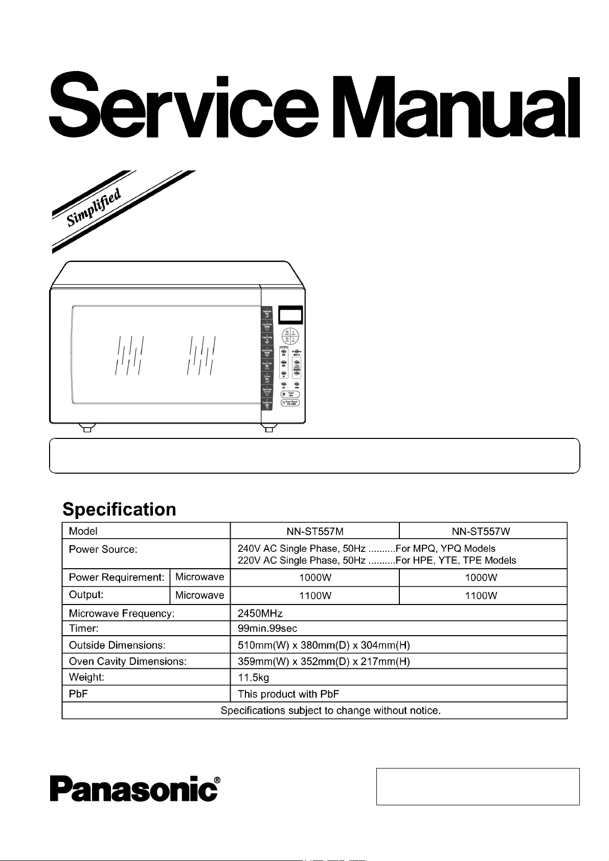
NN-ST557M
NN-ST557W
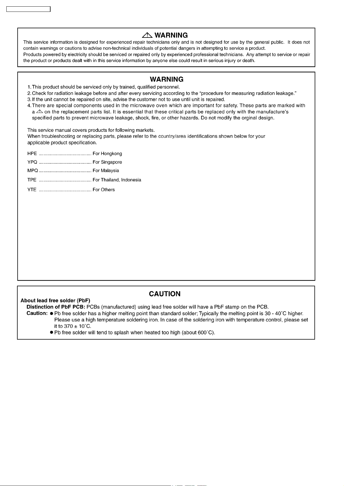
HPE(Hong Kong)
YPQ(Singapore)
MPQ(Malaysia)
TPE(Thailand, Indonesia)
YTE(Others)
ORDER NO.PHAMOS0709042A3
Microwave Oven
Please file and use this manual together with the service manual for Model NN-S553/K593/K573/K543
(ORDER NO. SIMMC0306022C3).
© 2007 Panasonic Home Appliances Microwave
Oven (Shanghai) Co., Ltd. All rights reserved.
Unauthorized copying and distribution is a violation
of law.
Page 2
NN-ST557M / NN-ST557W
2
Page 3
NN-ST557M / NN-ST557W
3
Page 4

NN-ST557M / NN-ST557W
CONTENTS
Page Page
1 SCHEMATIC DIAGRAM 5
2 CAUTIONS TO BE OBSERVED WHEN TROUBLESHOOTING
2.1. Check the grounding
2.2. Inverter warnings
2.3. Part replacement .
2.4. When the 10A fuse is blown due to the operation of the
short switch:
2.5. Avoid inserting nails, wire etc. through any holes in the
unit during operation.
2.6. Confirm after repair
2.7. Sharp edges
3 MEASUREMENTS AND ADJUSTMENTS
3.1. Adjustment of primary latch switch, secondary latch switch
and short switch.
6
6
6
7
7
7
7
7
8
8
3.2. Measurement of microwave output
4 EXPLODED VIEW AND PARTS LIST
4.1. EXPLODED VIEW
4.2. PARTS LIST
4.3. DOOR ASSEMBLY
4.4. WIRING MATERIALS
4.5. ESCUTCHEON BASE ASSEMBLY
4.6. PACKING AND ACCESSORIES
4.7. H.V. INVERTER MAIN PARTS LIST
5 DIGITAL PROGRAMMER CIRCUIT
5.1. SCHEMATIC DIAGRAM
5.2. PARTS LIST
8
9
9
10
11
11
12
13
13
14
14
16
4
Page 5
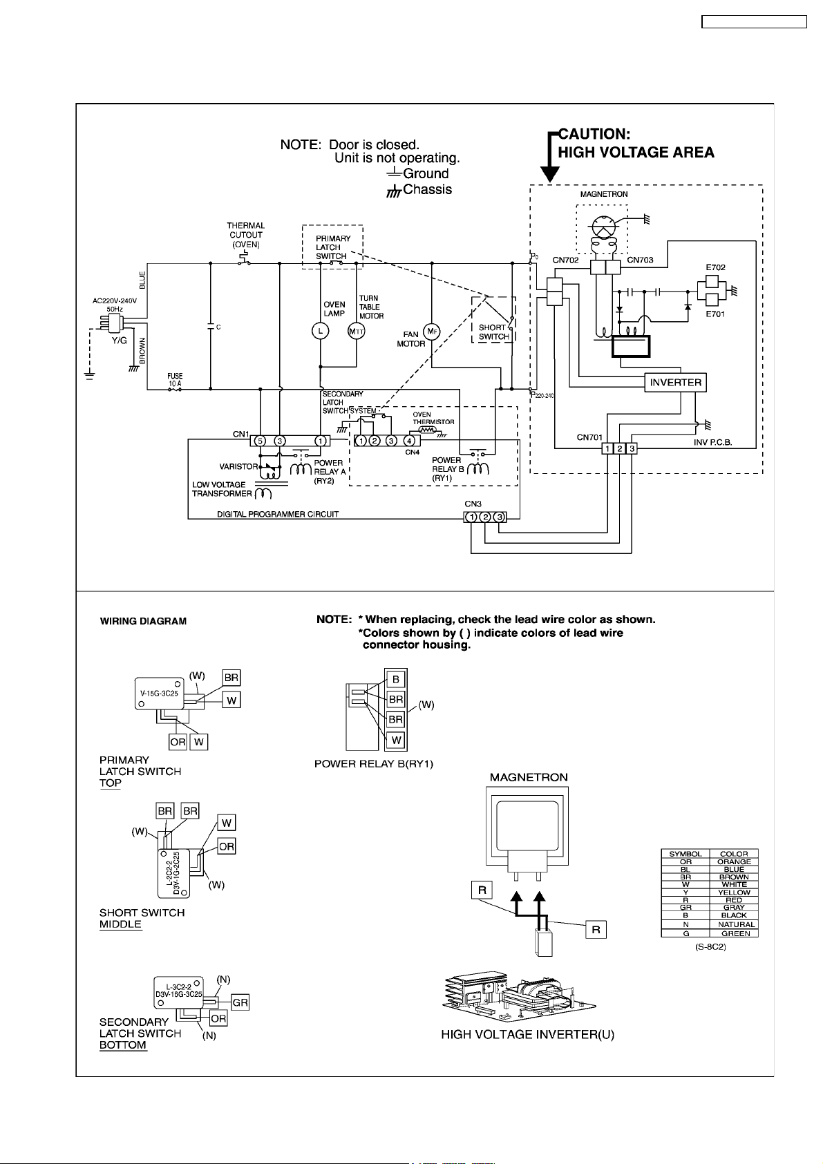
1 SCHEMATIC DIAGRAM
NN-ST557M / NN-ST557W
5
Page 6

NN-ST557M / NN-ST557W
2 CAUTIONS TO BE OBSERVED WHEN
TROUBLESHOOTING
Unlike many other appliances, the microwave oven is a high
voltage, high current device. It is free from danger in ordinary
use, though extreme care should be taken during repair.
CAUTION
Servicemen should remove their watches whenever
working close to or replacing the magnetron.
2.1. Check the grounding
Do not operate on a two wire extension cord. The microwave
oven is designed to be grounded when used. It is imperative,
therefore, to ensure the appliance is properly grounded before
beginning repair work.
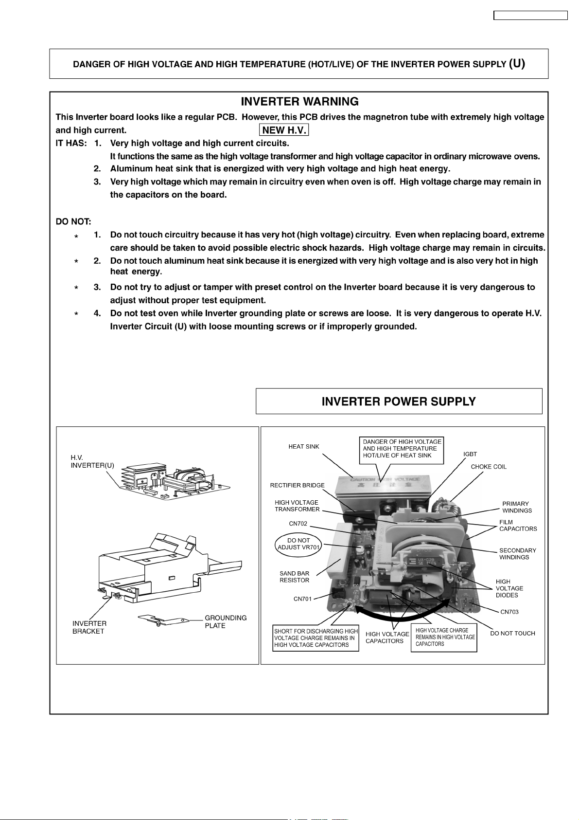
2.2. Inverter warnings
DANGER, HIGH VOLTAGE AND HIGH TEMPERATURE
(HOT/LINE) OF THE INVERTER POWER SUPPLY (U)
The high voltage inverter power supply handles very high
voltage and current for the magnetron tube. Though it is
free from danger in ordinary use, extreme care should be
taken during repair.
The aluminum heat sink is also energized with high voltage
(HOT), do not touch when the AC input terminals are
energized. The power device Collector is directly connected
to the aluminum heat sink.
The aluminum heat sink may be HOT due to heat energy,
therefore, extreme care should be taken during servicing.
Grounding of the inverter circuit board
WARNING! DISCHARGE THE HIGH VOLATGE
CAPACITORS
For about 30 seconds after the oven is turned off, an
electric charge remains in the high voltage capacitors in the
inverter power supply circuit board.
When replacing or checking parts, remove the power plug
from the outlet and short the inverter output terminal of the
magnetron filament terminals to the chassis ground with an
insulated handle screwdriver to discharge. Please be sure
to touch the chassis ground side first and then short to the
output terminals.
H.V. Inverter warning
WARNING FOR INVERTER POWER SUPPLY (U)
GROUNDING
Check the high voltage inverter power supply circuit
grounding. The high voltage inverter power supply circuit
board must have a proper chassis ground. The inverter
grounding bracket must be connected to the chassis. If the
inverter board is not grounded it will expose the user to very
high voltages and cause extreme DANGER! Be sure that
the inverter circuit is properly grounded via the inverter
earth bracket.
Discharging the high voltage capacitors
WARNING
There is high voltage present with high current capabilities
in the circuits of the primary and secondary windings, choke
coil and heat sink of the inverter. It is extremely dangerous
to work on or near these circuits with the oven energized.
DO NOT measure the voltage in the high voltage circuit
including the filament voltage of the magnetron.
WARNING
Never touch any circuit wiring with your hand or with an
insulated tool during operation.
6
Page 7

NN-ST557M / NN-ST557W
2.3. Part replacement.
When any part or component is to be replaced, always ensure
that the power cord is removed from the wall outlet.
2.4. When the 10A fuse is blown
due to the operation of the
short switch:
WARNING
When the 10A 250V fuse is blown due to the operation of
the interlock monitor switch, replace all of the components
(primary latch switch, secondary latch switch, short switch
and power relay B (RY1)).
1. This is mandatory. Refer to “adjustments and
measurements” for the location of these switches.
2. When replacing the fuse, confirm that it has the
appropriate rating for these models.
3. When replacing faulty switches, be sure the mounting
tabs are not bent, broken or deficient in their ability to
hold the switches.
2.5. Avoid inserting nails, wire etc.
through any holes in the unit
during operation.
2.7. Sharp edges
CAUTION
Please use caution when unpacking, installing or moving
the unit, as some exposed edges may be sharp to the touch
and cause injury if not handled with care.
Never insert a wire, nail or any other metal object through the
lamp holes on the cavity or any holes or gaps, because such
objects may work as an antenna and cause microwave
leakage.
2.6. Confirm after repair
1. After repair or replacement of parts, make sure that the
screws of the oven, etc. are neither loose nor missing.
Microwaves might leak if screws are not properly tightened.
2. Make sure that all electrical connections are tight before
inserting the plug into the wall outlet.
3. Check for microwave energy leakage. (Refer to procedure
for measuring microwave energy leakage).
CAUTION MICROWAVE RADIATION
USE CAUTION NOT TO BECOME EXPOSED TO
RADIATION FROM THE MICROWAVE MAGNETRON OR
OTHER PARTS CONDUCTING MICROWAVE ENERGY
IMPORTANT NOTICE
The following components have potentials above 2000V
while the appliance is operated.
•••• Magnetron
•••• High voltage transformer (Located on inverter (U))
•••• High voltage diodes (Located on inverter (U))
•••• High voltage capacitors (Located on inverter (U))
Pay special attention to these areas.
When the appliance is operated with the door hinges or
magnetron installed incorrectly, the microwave leakage can
exceed more than 5mW/c m
very important to check if the magnetron and the door
hinges are correctly installed.
2
. After repair or exchange, it is
7
Page 8

NN-ST557M / NN-ST557W
3 MEASUREMENTS AND ADJUSTMENTS
3.1. Adjustment of primary latch
switch, secondary latch switch
and short switch.
1. Mount the Primary latch switch, the secondary latch switch
and the short switch to the door hook assembly as shown in
ILL.
NOTE:
No specific individual adjustments during
installation of the Primary latch switch, Secondary
latch switch or Short switch to the door hook are
required.
2. When mounting the door hook assembly to the oven
assembly, adjust the door hook assembly by moving it in
the direction of the arrows in the illustration, so that the
oven door will not have any play in it. Check for play in the
door by pulling the door assembly. Make sure that the latch
keys move smoothly after adjustment is completed.
Completely tighten the screws holding the door hook
assembly to the oven assembly.
3. Reconnect the short switch and check the continuity of the
monitor circuit and all latch switches again by following the
component test procedures.
3.2. Measurement of microwave
output
The output power of the magnetron can be determined by
performing IEC standard test procedures. However,due to the
complexity of IEC test procedures, it is recommended to test
the magnetron using the simple method outlined below.
Necessary Equipment:
*1 liter beaker *Glass thermometer
*Wrist watch or stopwatch
NOTE:
Check the line voltage under load.Low voltage will
lower the magnetron output. Take the temperature
readings and heating time as accurately as possible.
1. Fill the beaker with exactly one liter of tap water.Stir the
water using the thermometer and record the water’s
temperature. (recorded as T1).
2. Place the beaker on the center of glass tray.
Set the oven for High power and heat it for exactly one
minute.
3. Stir the water again and read the temperature of the water.
(recorded as T2).
4. The normal temperature rise at High power level for each
model, is as shown in table.
TABLE (1L-1min.test)
RATED OUTPUT TEMPERATURE RISE
1100W Min. 9.4°C
8
Page 9

4 EXPLODED VIEW AND PARTS LIST
4.1. EXPLODED VIEW
NN-ST557M / NN-ST557W
9
Page 10

NN-ST557M / NN-ST557W
4.2. PARTS LIST
NOTE:
1. When ordering replacement part(s), please use part number(s) shown in this part list.
Do not use description of the part.
2. Important safety notice:
Components identified by
When replacing any of these components, use only manufacture’s specified parts.
Ref. No. Part No. Part Name & Description Pcs/Set Remarks
1 F00066V00HP CAUTION LABEL 1
6 F10016M60APG BASE 1
7 F10084T00AP RUBBER FOOT 4
8 F110D8G80SZP CABINET BODY 1 ST557M (HPE,YPQ,YTE)
8 F110D6W80SMP CABINET BODY 1 ST557M (MPQ)
8 F110D8U00HXP CABINET BODY 1 ST557W (HPE,YTE)
8 F110D8U00HMP CABINET BODY 1 ST557W (MPQ)
9 F200A6D60SXP OVEN 1
10 F20555Q00BP COVER 1
11 F21315G10XN PULLY SHAFT 1
12 F290D5Q00AP ROLLER RING (U) 1
13 F30205Q00AP DOOR HOOK 1
14 F31365Q00AP HOOK LEVER A 1
15 F400A5U00XN FAN MOTOR 1
mark have special characteristics important for safety.
16 F40085G10XN FAN BLADE 1
17 F40255Q00AP AIR GUIDE A 1
18 F40425Q00APG AIR GUIDE F 1
19 F612E8F60QP INCANDESCENT LAMP(U) 1
21 F41445Q00AP UPPER ORIFICE 1
26 F61425U30XN MICRO SWITCH 1 V-15G-3C25 (PRIMARY LATCH SWITCH)
27 F61415U30XN MICRO SWITCH 1 D3V-16G-3C25 (SECONDARY LATCH SWITCH)
28 F61785U30XN MICRO SWITCH 1 D3V-1G-2C25 (SHORT SWITCH)
29 2M261-M32KLP MAGNETRON 1
31 F62306V60BP FUSE 1 (10A)
32 MKPX2335K CAPACITOR 1
33 F62315G10XN FUSE HOLDER 1
34 F63265U30XN TURNTABLE MOTOR 1
35 F900C5Q00YK AC CORD W/PLUG 1 HPE,MPQ,YTE
35 F900C8G60ZP AC CORD W/PLUG 1 TPE
35 F900C5Q00YP AC CORD W/PLUG 1 YPQ
36 F606YM300BP H.V.INVERTER (U) 1
37 F65856M60AP INVERTER BRACKET 1
38 F66626H60AP GROUNDING PLATE 1
39 F61458B80ZP THERMAL CUTOUT 1
41 XTWFA4+12T SCREW 4 FOR MAGNETRON
44 XTWFA4+12D SCREW 4 FOR CABINET BODY
45 XTCAFA4+12AFS SCREW 1 FOR CABINET BODY SIDE (ST557M)
45 XTCAFA4+12AFW SCREW 1 FOR CABINET BODY SIDE (ST557W)
58 F20345Q00CP REINFORCE BRACKET 1
60 F11404J60XN STOPPER 2
62 F00066W10MP CAUTION LABEL 1 YPQ
62 F00068H00YT CAUTION LABEL 1 YTE
64 F0005-6S10 EARTH LABEL 1 TPE
10
Page 11

4.3. DOOR ASSEMBLY
NN-ST557M / NN-ST557W
Ref. No. Part No. Part Name & Description Pcs/Set Remarks
D1 F30185Q00AP DOOR KEY A 1
D3 F302K5Q00AP DOOR E(U) 1
D4 F30215G10XN DOOR KEY SPRING 1
D5 F30855Q00AP DOOR C 1
D6 F31456V60XP DOOR SCREEN A 1
D8 F302A8U20SXP DOOR A (U) 1 ST557M
D8 F302A8U20HXP DOOR A (U) 1 ST557W
4.4. WIRING MATERIALS
Ref. No. Part No. Part Name & Description Pcs/Set Remarks
W1 F030A8B90HP LEAD WIRE HARNESS 1
W2 F030E5Q00AP H.V.LEAD WIRE 1
W3 F03538U00XP LEAD WIRE HARNESS U 1 (INCLUDING THERMISTOR)
11
Page 12

NN-ST557M / NN-ST557W
4.5. ESCUTCHEON BASE ASSEMBLY
Ref. No. Part No. Part Name & Description Pcs/Set Remarks
E1 F603L8C20HP D.P. CIRCUIT (AU) 1
E4 F630Y8C20SHP MEMBRANE SWITCH(AU) 1 ST557M
E4 F630Y8C20HHP MEMBRANE SWITCH(AU) 1 ST557W
E5 F800L8C20SHP ESCUTCHEON BASE (U) 1 ST557M
E5 F800L8C20HHP ESCUTCHEON BASE (U) 1 ST557W
E6 F80728U10SXP DOOR OPENING BUTTON 1 ST557M
E6 F80728U10HXP DOOR OPENING BUTTON 1 ST557W
E7 F80375K00AP COOK BUTTON SPRING 1
E8 F82565Q00AP DOOR OPENING LEVEL 1
E12 F00078C20SHP NAME PLATE 1 ST557M HPE
E12 F00078C20SMP NAME PLATE 1 ST557M MPQ
E12 F00078C20SYP NAME PLATE 1 ST557M YPQ
E12 F00078C20STP NAME PLATE 1 ST557M TPE
E12 F00078C20HHP NAME PLATE 1 ST557W HPE
E12 F00078C20HMP NAME PLATE 1 ST557W MPQ
E12 F00078C20HYT NAME PLATE 1 ST557W YTE
E13 F630N8C20HP MEMBRANE SWITCH(BU) 1
12
Page 13

4.6. PACKING AND ACCESSORIES
NN-ST557M / NN-ST557W
Ref. No. Part No. Part Name & Description Pcs/Set Remarks
P1 F00038C20HP INSTRUCTION MANUAL 1
P2 F01028C20SYP PACKING CASE,PAPER 1 ST557M
P2 F01028C20HHP PACKING CASE,PAPER 1 ST557W
P3 F01045Q00AP UPPER FILLER 1
P4 F01055Q00AP LOWER FILLER 1
P5 F01068100XN P.E.BAG 1
P6 F01078J00XN DOOR SHEET 1
P7 F06015Q00AP COOKING TRAY 1
P8 F01924T00AP SHEET 1
P13 F04478C20BMP OVERLAY 1 ST557M (MPQ,YPQ), ST557W (MPQ)
P13 F04478C20BTP OVERLAY 1 ST557M (TPE)
P14 F000B6V70MP COOKING GUIDE 1
P20 F91644000XN EARTH LEAD 1 TPE
P21 F00324040XN EARTH CAUTION LABEL 1 TPE
P23 F04468C20BMP OVERLAY 1 ST557M (MPQ,YPQ)
P23 F04468C20BTP OVERLAY 1 ST557M (TPE)
P23 F04468C20HMP OVERLAY 1 ST557W (MPQ)
4.7. H.V. INVERTER MAIN PARTS LIST
Ref. No. Part No. Part Name & Description Pcs/Set Remarks
Q701 A691EM300BP IGBT 1
Q702 IGBT 1
C701 ECWF5184N300 FILM CAPACITOR 1
C702 ECQE2505T869 FILM CAPACITOR 1
C703 ECWF2395N632 FILM CAPACITOR 1
DB701 B0FBBS000001 RECTIFIER BRIDGE 1
L701 F5020M300GP CHOKE COIL 1
R702 D0CM352JA002 SAND BAR RESISTOR 1
T701 A609AM300GP TRANSFORMER 1 (INCLUDING D701, D702, C706, C707)
D701, D702 B0FBAZ000001 DIODE 2
C706 ECWH30562U03 FILM CAPACITOR 1
C707 ECWH30432U04 FILM CAPACITOR 1
13
Page 14

NN-ST557M / NN-ST557W
5 DIGITAL PROGRAMMER CIRCUIT
5.1. SCHEMATIC DIAGRAM
14
Page 15

NN-ST557M / NN-ST557W
15
Page 16

NN-ST557M / NN-ST557W
5.2. PARTS LIST
BZ210 L0DDEA000014 BUZZER 1 2.0KHz
C12 AECETK1V561B AL CHEM CAPACITOR 1 560µF/35V
C13,C16 AECETS1C220B AL CHEM CAPACITOR 2 22µF/16V
CX320 EFOEC8004A4 CERAMIC RESONATOR 1 8.0MHz
DISP110 L5AAAEC00057 LCD 1
DISP1 HOLDER F66174U20AP LCD HOLDER 1
D10-D13 B0EAKT000025 DIODE 4
D41,D220-D225,D227 MA2C19600E DIODE 8
D25 D4EAY511A036 VARSITOR 1 510V
D26,D27 D4EAY112A036 VARSITOR 2 1100V
IC1 MN101C78AEX L.S.I. 1
IC350 C0EBE0000401 IC 1
Q10,Q180 B1BAAJ000003 TRANSISTOR 2
R225 D0AE470JA155 CARBON RESISTOR 1 47ΩΩΩΩ,1/4W,5%
R211 D0AE102JA155 CARBON RESISTOR 1 1K,1/4W,5%
R210 D0AE332JA155 CARBON RESISTOR 1 3.3K,1/4W,5%
R228,R352 D0AE104JA155 CARBON RESISTOR 2 100K,1/4W,5%
RY1 AEBGJQC25F18 POWER RELAY 1
RY2 K6B1AZA00011 POWER RELAY 1
T10 G4C3AAH00008 LOW VOLTAGE TRANSFORMER 1
ZD10 B0BA5R600016 ZENER DIODE 1
ZD11 B0BA4R400002 ZENER DIODE 1
Ref. No. Part No. Part Name & Description Pcs/Set Remarks
16
09/07
S-8C2
Printed in China
 Loading...