

Panasonic NNSD297S Service Manual
© 2007 Panasonic Home Appliances Microwave
Oven (Shanghai) Co., Ltd. All rights reserved.
Unauthorized copying and distribution is a violation
of law.
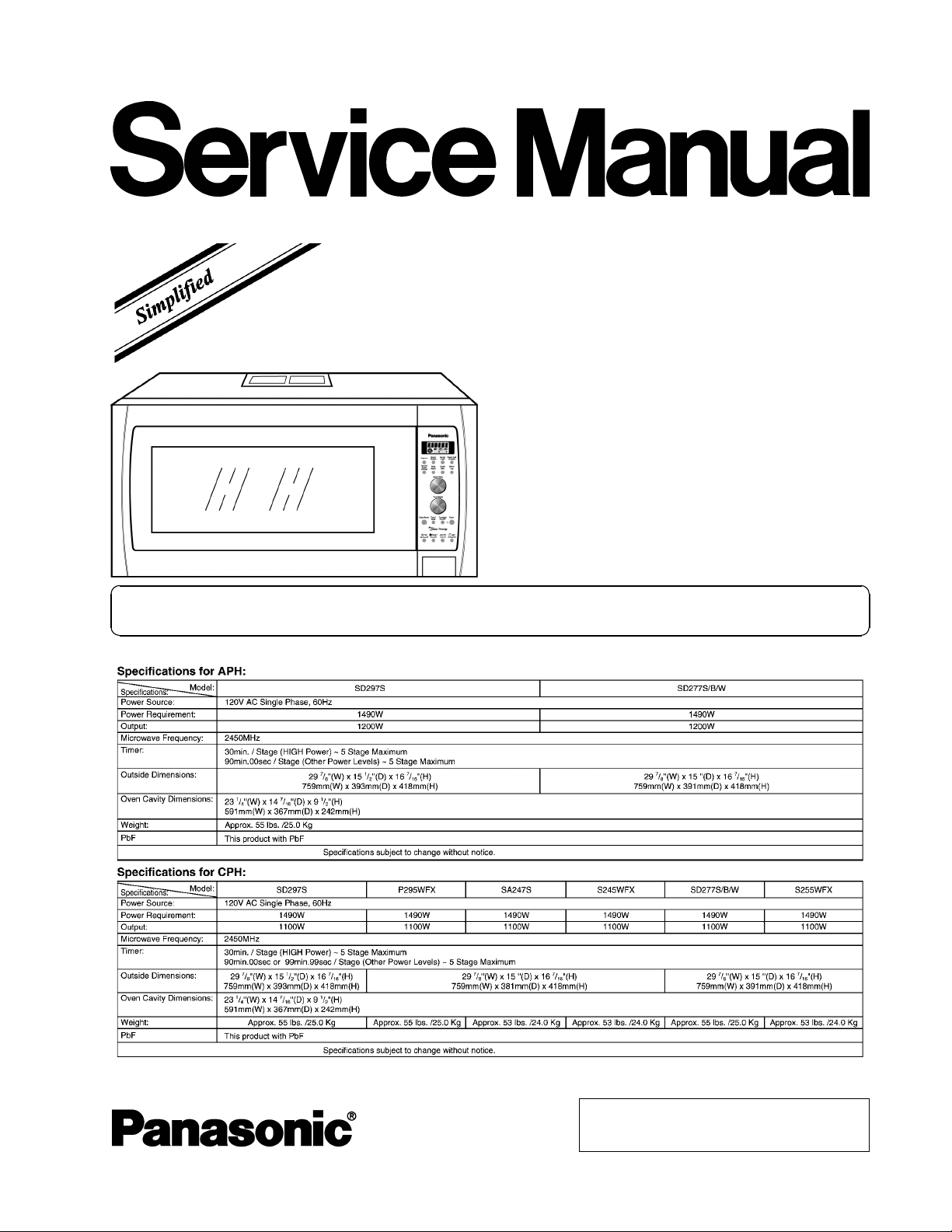
NN-SD297S
NN-SD277S
NN-SD277B
NN-SD277W
NN-SA247S
NN-P295WFX
NN-S255WFX
NN-S245WFX
APH(USA)
CPH(CANADA)
Microwave Oven
Please file and use this manual together with the service manual for Model NN-S262SF (Order
No.SIMMC0203005C1)
ORDER NO.PHAMOS0705024A1
E2
2
NN-SD297S / NN-SD277S / NN-SD277B / NN-SD277W / NN-SA247S / NN-P295WFX / NN-S255WF X / NN-S245WFX
3
NN-SD297S / NN-SD277S / NN-SD277B / NN-SD277W / NN-SA247S / NN-P295WFX / NN-S255WF X / NN-S245WFX

1 SCHEMATIC DIAGRAM 5
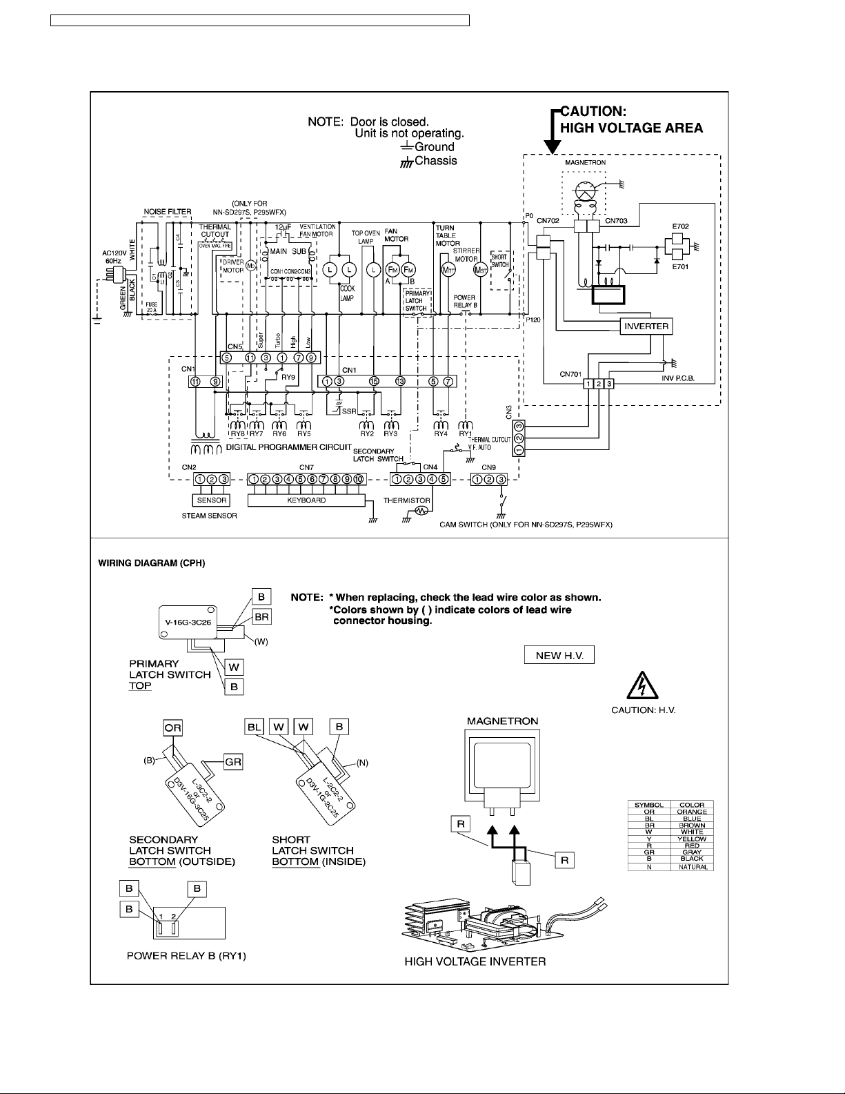
1.1. APH (NN-SD297S, SD277S/B/W )
5
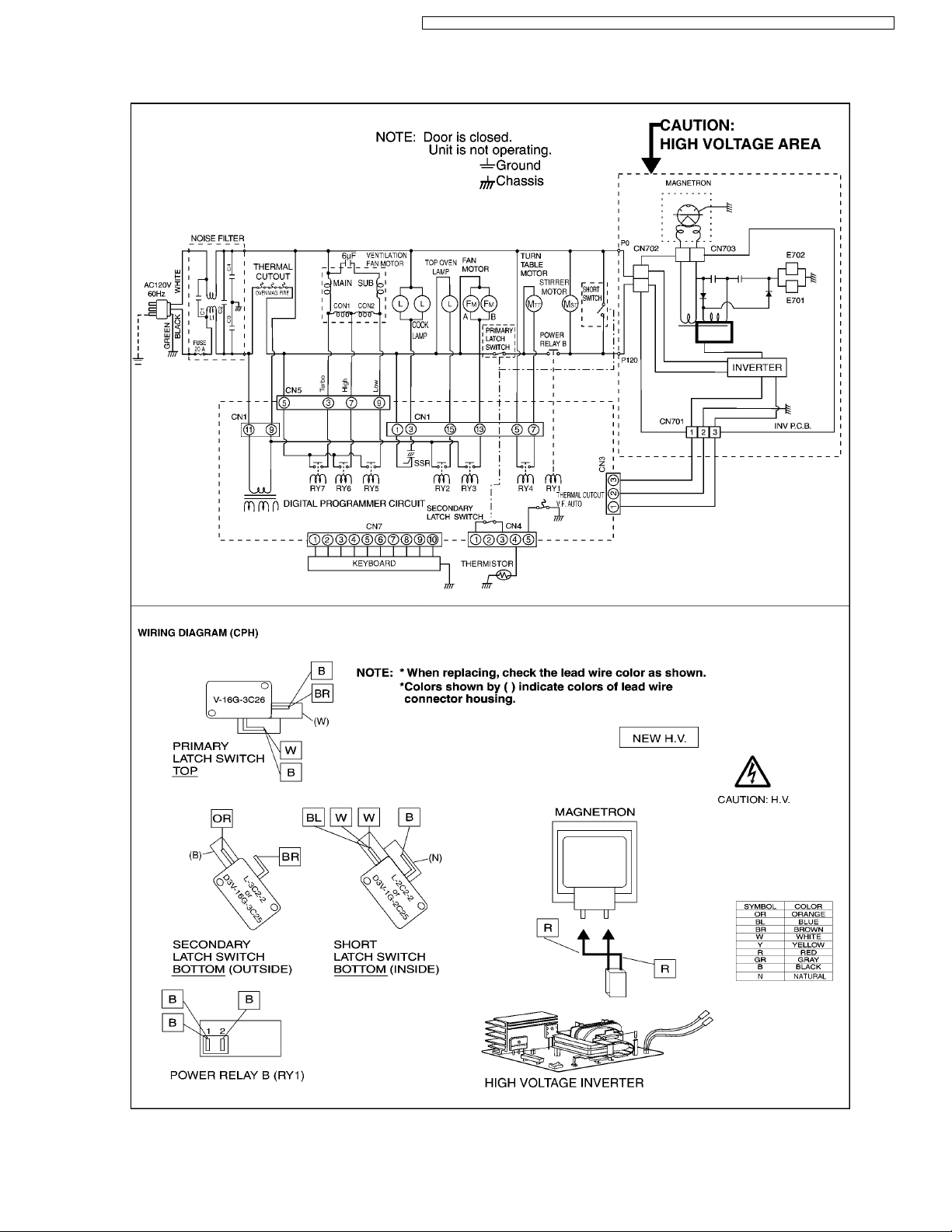
1.2. CPH (NN-SD297S, SD277S/B/W , P295WFX)
6
1.3. CPH (NN-SA247S, S255WFX, S245WFX)
7
2 MEASUREMENTS AND ADJUSTMENTS
8
2.1. Adjustment of primary latch switch, secondary latch switch
and short switch.
8
2.2. Measurement of microwave output
8
3 PROCEDURE FOR MEASURING MICROWAVE ENERGY
LEAKAGE
9
3.1. Equipment
9
3.2. Procedure for measuring radiation leakage
9
3.3. Record keeping and notification after measurement
9
3.4. At least once a year, have the radiation monitor checked
for calibration by its manufacturer.
10
4 SIMPLE WAY OF H.V. INVERTER/MAGNETRON
TROUBLESHOOTING
11
5 H.V.INVERTER BOARD MAIN PARTS LIST (F606Y8M00AP)
11
6 EXPLODED VIEW AND PARTS LIST
12
6.1. EXPLODED VIEW
12
6.2. PARTS LIST
13
6.3. DOOR ASSEMBLY
15
6.4. ESCUTCHEON BASE ASSEMBLY
16
6.5. PACKING AND ACCESSORIES
20
6.6. WIRING MATERIALS
21
7 DIGITAL PROGRAMMER CIRCUIT
22
7.1. NN-SD297S APH/CPH
22
7.2. NN-P295WFX CPH
24
7.3. NN-SD277 APH/CPH, NN-S255WF X CPH
26
7.4. NN-SA247S CPH, S245WFX CPH
28
7.5. PARTS LIST
30
CONTENTS
Page Page
4
NN-SD297S / NN-SD277S / NN-SD277B / NN-SD277W / NN-SA247S / NN-P295WFX / NN-S255WF X / NN-S245WFX
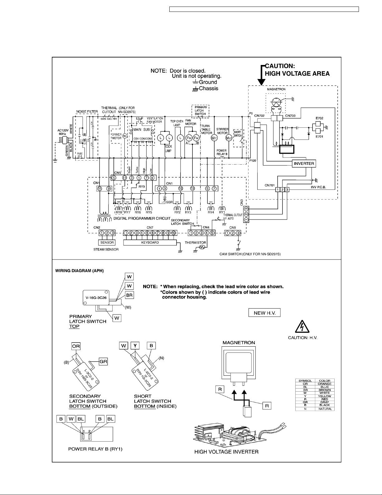
1 SCHEMATIC DIAGRAM
1.1. APH (NN-SD297S, SD277S/B/W)
5
NN-SD297S / NN-SD277S / NN-SD277B / NN-SD277W / NN-SA247S / NN-P295WFX / NN-S255WF X / NN-S245WFX
1.2. CPH (NN-SD297S, SD277S/B/W, P295WFX)
6
NN-SD297S / NN-SD277S / NN-SD277B / NN-SD277W / NN-SA247S / NN-P295WFX / NN-S255WF X / NN-S245WFX
1.3. CPH (NN-SA247S, S255WFX, S245WFX)
7
NN-SD297S / NN-SD277S / NN-SD277B / NN-SD277W / NN-SA247S / NN-P295WFX / NN-S255WF X / NN-S245WFX
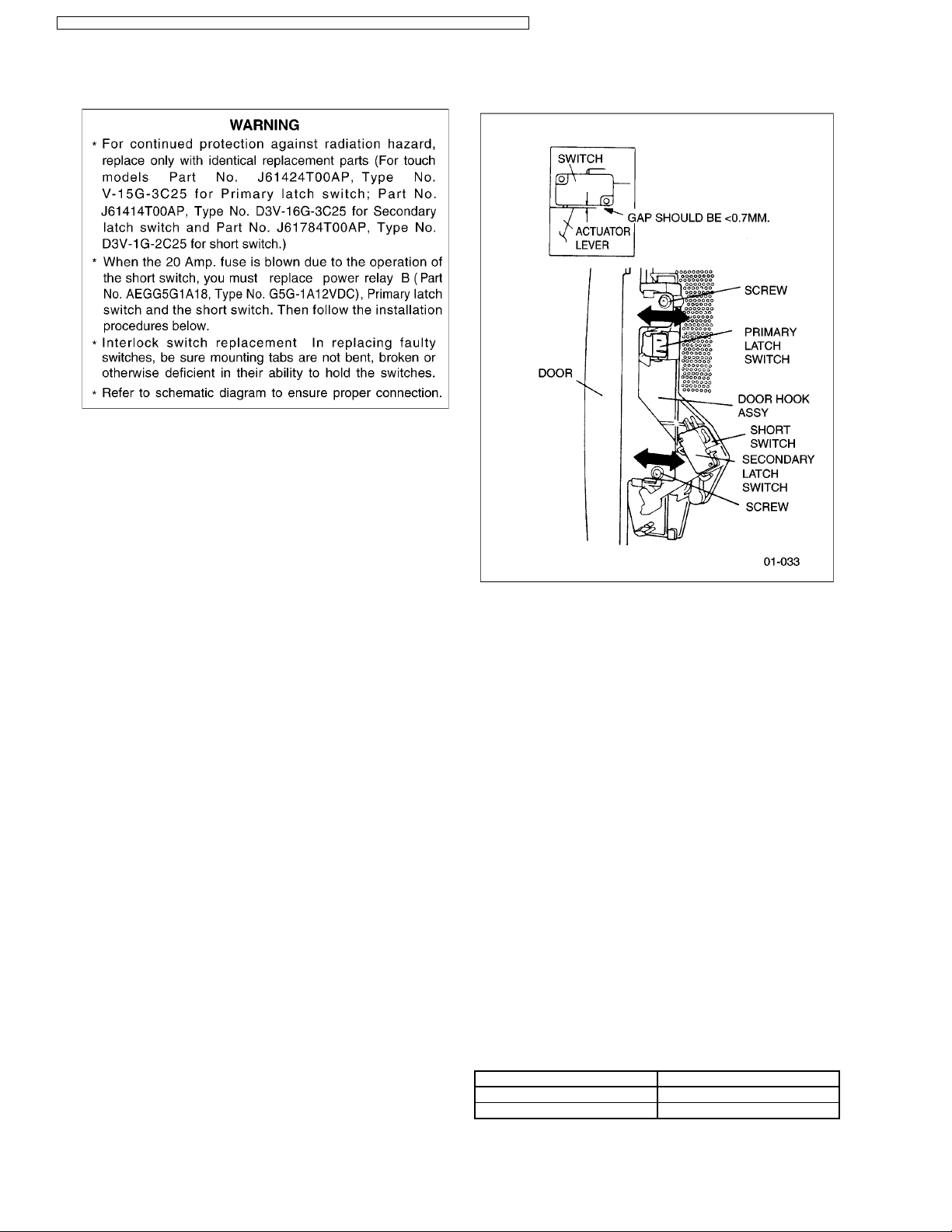
2.1. Adjustment of primary latch
switch, secondary latch switch
and short switch.
1. Mount the Primary latch switch, the Second ary latch switch
and the short switch to the door hook assembly as shown in
ILL.
NOTE:
No specific individual adjustments during
installation of the Primary latch switch, Secondary
latch switch or Short switch to the door hook are
required.
2. When mounting the door hook assembly to the oven
assembly, adjust the door hook assembly by moving it in
the direction of the arrows in the illustration so that the oven
door will not have any play in it. Check for play in the door
by pulling the door assembly. Make sure that the latch keys
move smoothly after adjustment is completed. Completely
tighten the screws holding the door hook assembly to the
oven assembly.
3. Reconnect the short switch and check the continuity of the
monitor circuit and all latch switches again by following the
component test procedures.
2.2. Measurement of microwave
output
The output power of the magnetron can be determined by
performing IEC standard test procedures. However,due to the
complexity of IEC test procedures, it is recommended to test
the magnetron using the simple method outlined below.
Necessary Equipment:
*1 liter beaker *Glass thermometer
*Wrist watch or stopwatch
NOTE:
Check the line voltage under load.Low voltage will
lower the magnetron output. Take the temperature
readings and heating time as accurately as possible.
1. Fill the beaker with exactly one liter of tap water.Stir the
water using the thermometer and record the water’s
temperature. (recorded as T1).
2. Place the beaker on the center of glass tray.
Set the oven for High power and heat it for exactly one
minute.
3. Stir the water again and read the temperature of the water.
(recorded as T2).
4. The normal temperature rise at High power level for each
model is as shown in table.
TABLE (1L-1min.test)
RATED OUTPUT TEMPERATURE RISE
1100W Min. 16.9°F(9.4°C )
1200W Min. 18.5°F(10.3°C)
2 MEASUREMENTS AND ADJUSTMENTS
8
NN-SD297S / NN-SD277S / NN-SD277B / NN-SD277W / NN-SA247S / NN-P295WFX / NN-S255WF X / NN-S245WFX
NOTE:
The U.S. Government standard is 5 mW/cm
2
while in the
customer’s home. 2mW/cm
2
stated here is our own
voluntary standard. (1mW/cm
2
for Canada)
3.1. Equipment
•••• Electromagnatic radiation monitor
•••• Glass thermometer 212°F or 100°C
•••• 600cc glass beaker
3.2. Procedure for measuring
radiation leakage
Note before measuring.
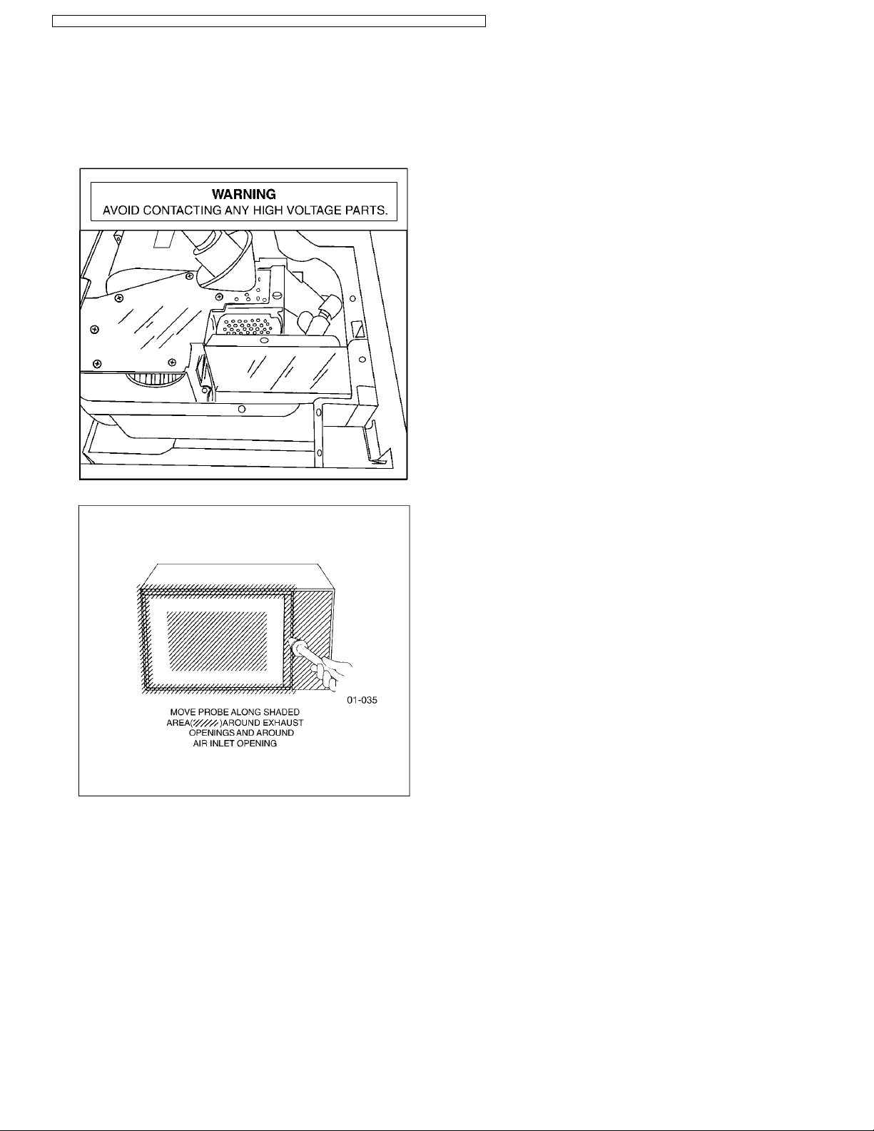
•••• Do not exceed meter full scale deflection. Leakage monitor
should initially be set to the highest scale.
•••• To prevent false readings the test probe should be held by
the grip portion of the handle only and moved along the
shaded area in Figure no faster than 1 inch/sec
(2.5cm/sec).
•••• Leakage with the outer panel removed ...... less than
5mW/cm
2
.
•••• Leakage for a fully assembled oven with door normally
closed ...... less than 2mW/c m
2
(1mW/cm2for Canada).
•••• Leakage for a fully assembled oven [Before the latch switch
(primary) is interrupted] while pulling the door ...... less than
2mW/cm
2
.
1. Pour 275 ± 15cc (9ozs
s
± 1/2oz) of 20°C ± 5°C (68° ± 9°F)
water in a beaker which is graduated to 600cc, and place in
the center of the oven.
2. Set the radiation monitor to 2450MHz and use it following
the manufacturer´s recomm ended test procedure to assure
correct results.
3. When measuring the leakage, always use the 2 inch (5cm)
spacer supplied with the probe.
4. Tap the start pad or set the timer and with the magnetron
oscillating, measure the leakage by holding the probe
perpendicular to the surface being measured.
3.2.1. Measurement with the outer panel
removed.
Whenever you replace the magnetron, measure for radiation
leakage before the outer panel is installed and after all
necessary components are replaced or adjusted. Special care
should be taken in measuring around the magnetron.
3.2.2. Measurements with a fully
assembled oven.
After all components, including outer panel are fully assembled,
measure for radiation leakage around the door periphery, the
door viewing window, the exhaust opening, control panel and
air inlet openings.
3.3. Record keeping and
notification after measurement
•••• After any adjustment or repair to a microwave oven, a
leakage reading must be taken. Record this leakage
reading on the repair ticket even if it is zero.
A copy of this repair ticket and the microwave leakage
reading should be kept by repair facility.
•••• Should the radiation leakage be more than 2 mW/cm
2
(1mW/cm2for Canada) after determining that all parts are in
good condition, functioning properly, and genuine
replacement parts as listed in this manual have been used,
immediately notify PSTC, PSC or PCI.
3 PROCEDURE FOR MEASURING MICROWAVE ENERGY
LEAKAGE
9
NN-SD297S / NN-SD277S / NN-SD277B / NN-SD277W / NN-SA247S / NN-P295WFX / NN-S255WF X / NN-S245WFX
3.4. At least once a year, have the
radiation monitor checked for
calibration by its
manufacturer.
10
NN-SD297S / NN-SD277S / NN-SD277B / NN-SD277W / NN-SA247S / NN-P295WFX / NN-S255WF X / NN-S245WFX
 Loading...