

Page 1
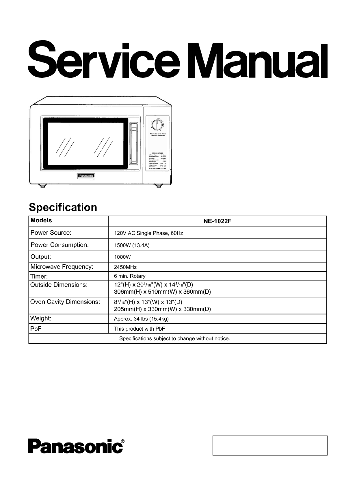
NE-1022F
APH (USA)
ORDER NO.PAPMOSH1201014CE
E10
Microwave Oven
© Panasonic Appliances Microwave Oven
(Shanghai) Co., Ltd. 2012.
Page 2
NE-1022F
2
Page 3

NE-1022F
CONTENTS
Page Page
1 CONTROL PANEL 4
2 SCHEMATIC DIAGRAM
3 CAUTIONS TO BE OBSERVED WHEN TROUBLESHOOTING
3.1. Check the grounding
3.2. Warning about the electric charge in the high voltage
capacitor
3.3. Part replacement.
3.4. When the 18 Amp fuse is blown due to the malfunction of
the monitor interlock switch:
3.5. Avoid inserting nails, wire, etc. through any holes in the
unit during operation.
3.6. Verification after repair
4 DISASSEMBLY AND PARTS REPLACEMENT PROCEDURE
4.1. Magnetron
4.2. Fan motor
4.3. Stirrer motor
4.4. Door assembly
4.5. Floor shelf and/or moving antenna
5 COMPONENT TEST PROCEDURE
5.1. Primary, Secondary Interlock Switch
5.2. Monitor Interlock Switch
5.3. High voltage transformer
5.4. High voltage capacitor
5
6
6
6
6
6
6
6
7
7
7
7
8
8
9
9
9
9
9
5.5. Magnetron
5.6. Diode
5.7. Protector diode
6 MEASUREMENTS AND ADJUSTMENTS
6.1. Adjustment of primary interlock switch, secondary interlock
switch and monitor interlock switch.
6.2. Measurement of microwave output
7 PROCEDURE FOR MEASURING MICROWAVE ENERGY
LEAKAGE
7.1. Equipment
7.2. Procedure for measuring radiation leakage
7.3. Record keeping and notification after measuremen t
7.4. At least once a year, have the radiation monitor checked
for calibration by its manufacturer.
8 TROUBLESHOOTING GUIDE
8.1. How to check the semiconductors using an OHM meter
9 EXPLODED VIEW AND PARTS LIST
9.1. EXPLODED VIEW
9.2. PARTS LIST
9.3. ESCUTCHEON BASE ASSEMBLY
9.4. DOOR ASSEMBLY
9.5. WIRING MATERIALS
9.6. PACKING AND ACCESSORIES
10
10
11
11
11
12
12
12
12
13
14
15
16
16
17
18
19
20
21
9
3
Page 4
NE-1022F
1 CONTROL PANEL
4
Page 5
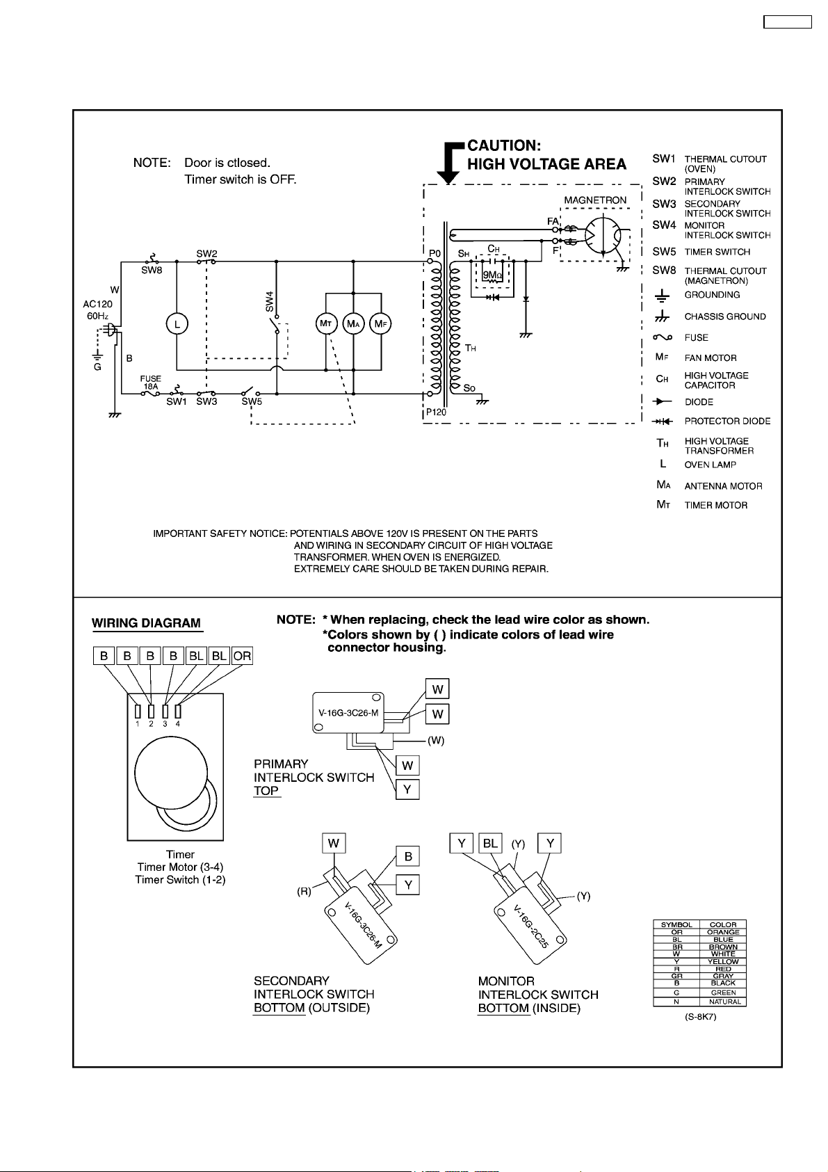
2 SCHEMATIC DIAGRAM
NE-1022F
5
Page 6
NE-1022F
3 CAUTIONS TO BE OBSERVED WHEN
TROUBLESHOOTING
Unlike many other appliances, the microwave oven is high
voltage, high current device. Though it is free from danger in
ordinary use, extreme care should be taken during repair.
CAUTION
Servicemen should remove their watches and rings whenever working
close to or replacing the magnetron.
3.1. Check the grounding
Do not operate on a 2-wire extension cord. The microwave
oven is designed to be grounded when used. It is imperative,
therefore, to make sure it is grounded properly before
beginning repair work.
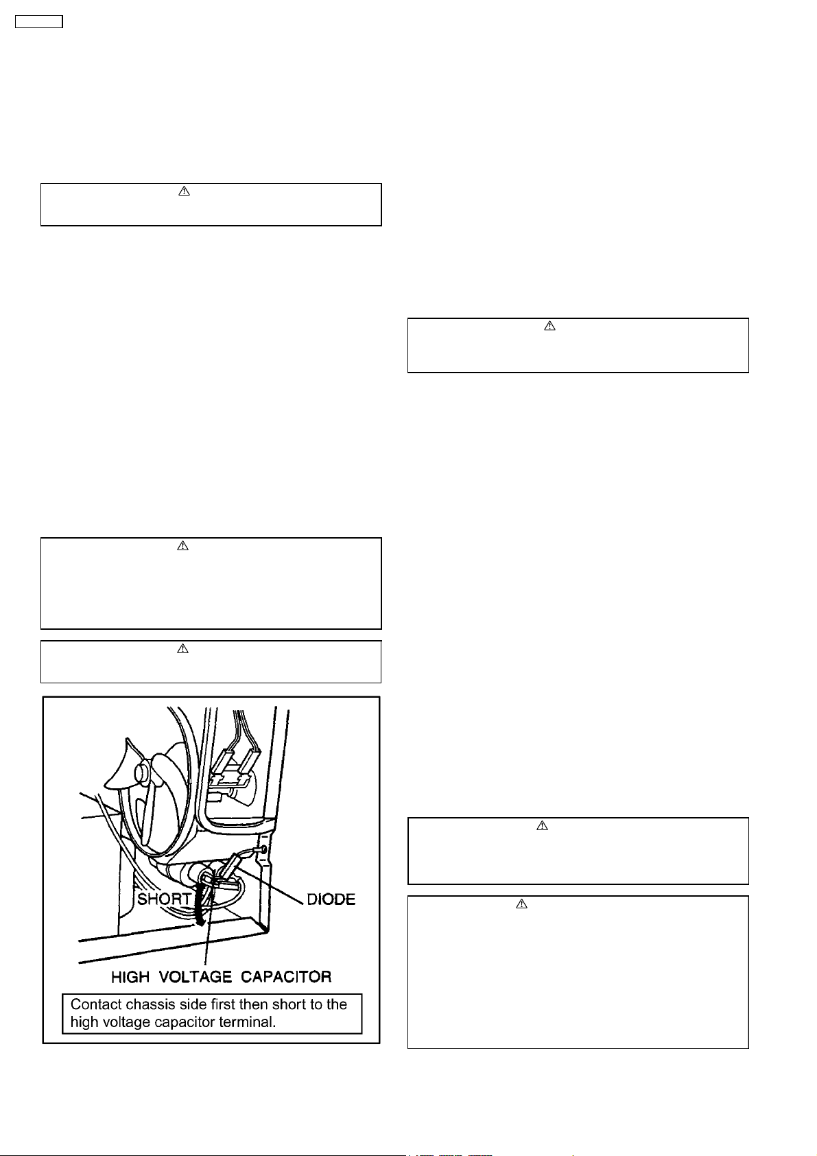
3.2. Warning about the electric
charge in the high voltage
capacitor
For about 30 seconds after the oven is turned off, an electric
charge remains in the high voltage capacitor.When replacing or
checking parts, remove the power plug from the outlet and
short the terminal of the high voltage capacitor (terminal of lead
wire from diode) to chassis ground with an insulated handle
screwdriver to discharge. Please be sure to contact the chassis
ground side first and then short to the output terminal.
WARNING
There is high voltage present with high current capabilities in the
circuits of the primary and secondary winding and filament winding of
the high voltage transformer. It is extremely dangerous to work on or
near these circuits with the oven energized.
DO NOT measure the voltage in the high voltage circuit including
filament voltage of the magnetron.
WARNING
Never touch any circuit wiring with your hand nor with an insulated
tool during operation.
3.3. Part replacement.
When troubleshootin g any part of component is to be replaced,
always ensure that the power cord is unplugged from the wall
outlet.
3.4. When the 18 Amp fuse is
blown due to the malfunction
of the monitor interlock
switch:
WARNING
When the 10 Amp fuse is blown due to malfunction of the short
switch, replace all of the components (Primary interlock switch,
Secondary interlock switch, Monitor interlock switch).
1. This is mandatory. Refer to “Measurements and
Adjustments” for the location of these switches.
2. When replacing the fuse, confirm that it has the appropriate
rating for these models.
3. When replacing faulty switches, be sure mounting tabs are
not bent, broken or deficient in their ability to hold the
switches.
3.5. Avoid inserting nails, wire, etc.
through any holes in the unit
during operation.
Never insert a wire, nail or any other metal object through the
lamp holes on the cavity or any holes or gaps, because such
objects may work as an antenna and cause microwave
leakage.
3.6. Verification after repair
1. After repair or replacement of parts, make sure that the
screws of the oven, etc. are neither loose nor missing.
Microwave energy might leak if screws are not properly
tightened.
2. Make sure that all electrical connections are tight before
inserting the plug into the wall outlet.
3. Check for microwave energy leakage.
MICROWAVE RADIATION OF LEAKAGE
USE CAUTION NOT TO BECOME EXPOSED TO RADIATION
FROM THE MICROWAVE MAGNETRON OR OTHER PARTS
CONDUCTING MICROWAVE ENERGY.
1.The following components have potentials above 2000V while the
appliance is operated.
* Magnetron
* High voltage transformer
* High voltage diode
* High voltage capacitor
Pay special attention to these areas.
2.When the appliance is operated with the door hinges or magnetron
installed incorrectly, the microwave leakage can exceed more than
5mW/cm
magnetron and the door hinges are is correctly installed.
2
. After repair or exchange, it is very important to check if the
CAUTION OF
IMPORTANT NOTICE
6
Page 7
4 DISASSEMBLY AND PARTS REPLACEMENT
PROCEDURE
NE-1022F
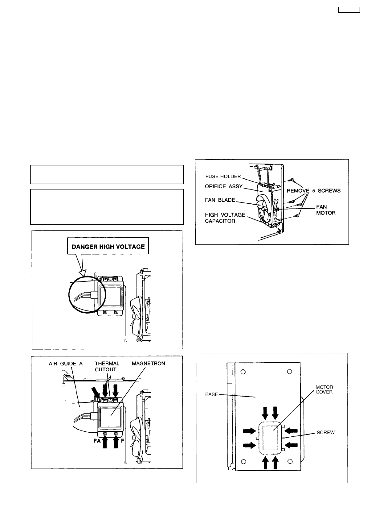
4.1. Magnetron
1. Discharge the high voltage capacitor.
2. Remove 2 screws holding magnetron thermal cutout.
3. Remove 1 screw holding air guide A.
4. Disconnect 2 high voltage lead wires from magnetron
filament terminals.
5. Remove 4 screws holding the magnetron.
NOTE:
After replacement of the magnetron, tighten mounting
screws properly making sure there is no gap between
the waveguide and the magnetron to prevent
microwave leakage.
CAUTION
When replacing the magnetron, be sure the antenna gasket is in
place.
CAUTION
When connecting 2 filament lead wires to the magnetron terminals,
be sure to connect the lead wires in the correct position. The lead wire
of high voltage transformer should be connected to "F terminal" and
the lead wire from high voltage capacitor should be connected to "FA
terminal".
4.2. Fan motor
1. Disconnect 2 lead wires from fan motor terminals.
2. Disconnect 2 lead wires from fuse holder terminals.
3. Disconnect 4 high voltage lead wires from high voltage
capacitor terminals.
4. Remove 5 screws holding fan motor and orifice assy,
detach the orifice assy with fan motor from oven assy.
5. Remove fan blade from the fan motor shaft by pulling it
straight Out.
6. Separate the fan motor from the orifice assy by freeing 2
catch hooks on the orifice assy.
4.3. Stirrer motor
1. Remove the motor cover by breaking off at the 8 spots
indicated by arrows with a cutter or the like. (See Figure)
Note:
After breaking off the motor cover, make sure the cut-off
portions are properly trimmed off or bend to inside so
that no sharp edge will expose to outside.
2. Disconnect 2 lead wires connected to the stirrer motor.
3. Remove the stirrer motor by removing 2 screws.
Note:
To reinstall the motor cover, use 4x6 screw.
7
Page 8

NE-1022F
4.4. Door assembly
1. Open the door and remove door C from door E by carefully
pulling outward starting from upper right hand corner.
2. Remove door key and door key spring.
3. Remove 2 screws holding side frame of door A.
4. Seperate the door A from the door E by freeing catch hooks
on the door A using a flat screwdriver.
To re-install components:
NOTE:
After replacement of the defective component parts
of the door, reassemble it properly and adjustment
so as to prevent an excessive microwave leakage.
Adjustment of the door assembly (Refer page 11).
5. When mounting the door to the oven, be sure to adjust the
door parallel to the bottom line of the oven face plate by
moving the upper hinge and lower hinge in the direction
necessary for proper alignment.
6. Adjust so that the door has no play between the inner door
surface and oven front surface. If the door assembly is not
mounted properly, microwave power may leak from the
clearance between the door and oven.
NOTE:
Door alignment is crucial. If door is misaligned, apply
pressure until alignment is achieved.
NOTE:
Adjust so that the upper portion of the door will touch
firmly to the oven cavity front plate, without pushing the
door. If the door assembly is not mounted properly,
microwave power may leak from the clearance between
the door and oven.
NOTE:
Always perform the microwave leakage measurement
test after installation and adjustment of door assembly.
4.5. Floor shelf and/or moving
antenna
1. Insert a phillips type screwdriver or equivalent approx. 2"
(5 cm) in shaft length in the access hole in the left side oven
wall as shown in Figure.
2. Carefully lift up the floor shelf by prying up with the
screwdriver until the floor shelf is lifted up over the level of
oven front opening.
3. Remove the floor shelf by lifting it out through the oven
front.
To replace moving antenna.
4. Remove the moving antenna by simply lifting it up off the
stirrer motor shaft.
NOTE:
When replacing the moving antenna, make sure the
plastic stirrer spacers are correctly in place. They
are necessary to stabilize the antenna by gliding
around the oven bottom as the antenna turns.
Be sure the gap between door E and cavity front plate will be
0.3~0.8mm.
8
Page 9

5 COMPONENT TEST PROCEDURE
NE-1022F
WARNING
1. High voltage is present at the high voltage terminal of the high
voltage transformer during any cook cycle.
2. It is neither necessary nor advisable to attempt measurement of the
high voltage.
3. Before touching any oven components, or wiring, always unplug
the power cord and discharge the high voltage capacitor (see page 6).
5.1. Primary, Secondary Interlock
Switch
1. Unplug lead connectors to Primary Interlock Switch and
Secondary Interlock Switch.
2. Test the continuity of switches at door opened and closed
positions with ohm meter (low scale).
Normal continuity readings should be as follows.
5.2. Monitor Interlock Switch
1. Unplug lead wires from H.V.transformer primary terminals.
2. Connect test probes of ohm meter to the disconnected
leads of the H.V. Transformer.
3. Test the continuity of Monitor Interlock Switch with door
opened and closed positions using lowest scale of the ohm
meter.
Normal continuity readings should be as follows.
5.3. High voltage transformer
1. Remove connectors from the transformer terminals and
check continuity.
2. Normal (cold) resistance readings should be as follows:
Secondary winding......................... Approx. 60 Ω~120 Ω
Filament winding........... ................... Approx. 0 Ω
Primary winding................................. Approx. 0 Ω ~2 Ω
5.4. High voltage capacitor
1. Check continuity of capacitor with meter on highest OHM
scale.
2. A normal capacitor will show continuity for a short time, and
then indicate 9MΩ once the capacitor is charged.
3. A shorted capacitor will show continuous continuity.
4. An open capacitor will show constant 9MΩ.
5. Resistance between each terminal and chassis should be
infinite.
5.5. Magnetron
Continuity checks can only indicate an open filament or a
shorted magnetron. To diagnose for an open filament or
shorted magnetron:
1. Isolate magnetron from the circuit by disconnecting the
leads.
2. A continuity check across magnetron filament terminals
should indicate one ohm or less.
3. A continuity check between each filament terminal and
magnetron case should read open.
9
Page 10

NE-1022F
5.6. Diode
1. Isolate the diode from the circuit by disconnecting the leads.
2. With the ohmmeter set on the highest resistance scale,
measure the resistance across the diode terminals.
Reverse the meter leads and again observe the resistance
reading. Meter with 6V, 9V or higher voltage batteries
should be used to check the front-to-back resistance of the
diode, otherwise an infinite resistance may be read in both
directions.
A normal diode´s resistance will be infinite in one direction
and several hundred kΩ in the other direction.
5.7. Protector diode
1. Isolate the protector diode assembly from the circuit by
disconnecting its leads.
2. With the ohmmeter set on the highest resistance scale,
measure the resistance across the protector diode
terminals.
Reverse the meter leads and again observe the resistance
reading. A normal protector diode´s resistance will be
infinite in both directions.
It is faulty if it shows continuity in one or both directions.
10
Page 11

6 MEASUREMENTS AND ADJUSTMENTS
6.1. Adjustment of primary
interlock switch, secondary
interlock switch and monitor
interlock switch.
NE-1022F
1. Mount the Primary interlock switch, the Secondary interlock
switch and the Monitor Interlock switch to the door hook
assembly as shown in illustration.
NOTE:
No specific individual adjustments during
installation of the Primary interlock switch,
Secondary interlock switch or Monitor interlock
switch to the door hook are required.
2. When mounting the door hook assembly to the oven
assembly, adjust the door hook assembly by moving it in
the direction of the arrows in the illustration so that the oven
door will not have any play in it. Check for play in the door
by pulling the door assembly. Make sure that the latch keys
move smoothly after adjustment is completed. Completely
tighten the screws holding the door hook assembly to the
oven assembly.
3. Reconnect the monitor interlock switch and check the
continuity of the monitor circuit and all interlock switches
again by following the component test procedures.
6.2. Measurement of microwave
output
The output power of the magnetron can be determined by
performing IEC standard test procedures. However, due to the
complexity of IEC test procedures, it is recommended to test
the magnetron using the simple method outlined below.
Necessary Equipment:
*1 liter beaker *Glass thermometer
*Wrist watch or stopwatch
NOTE:
Check the line voltage under load. Low voltage will
lower the magnetron output. Take the temperature
readings and heating time as accurately as possible.
1. Fill the beaker with exactly one liter of tap water. Stir the
water using the thermometer and record the water’s
temperature. (recorded as T1).
2. Place the beaker on the center of glass tray.
Set the oven for High power and heat it for exactly one
minute.
3. Stir the water again and read the temperature of the water.
(recorded as T2).
4. The normal temperature rise at High power level for each
model is as shown in table.
TABLE (1L-1min. test)
RATED OUTPUT TEMPERATURE RISE
1000W Min. 15.4°F(8.6°C )
11
Page 12

NE-1022F
7 PROCEDURE FOR MEASURING MICROWAVE ENERGY
LEAKAGE
7.2.1. Measurement with the outer panel
removed.
Whenever you replace the magnetron, measure for radiation
leakage before the outer panel is installed and after all
necessary components are replaced or adjusted. Special care
should be taken in measuring around the magnetron.
NOTE:
The U.S. Government standard is 5 mW/cm
customer’s home. 2mW/cm
voluntary standard. (1mW/cm
2
stated here is our own
2
for Canada)
2
while in the
7.1. Equipment
• Electromagnatic radiation monitor
• Glass thermometer 212°F or 100°C
• 600cc glass beaker
7.2. Procedure for measuring
radiation leakage
Note before measuring:
• Do not exceed meter full scale deflection. Leakage monitor
should initially be set to the highest scale.
• To prevent false readings, the test probe should be held by
the grip portion of the handle only and moved along the
shaded area in Figure no faster than 1 inch/sec
(2.5cm/sec).
• Leakage with the outer panel removed: less than 5mW/c m
• Leakage for a fully assembled oven with door normally
closed: less than 2mW/cm
• Leakage for a fully assembled oven [Before the latch switch
(primary) is interrupted] while pulling the door: less than
2mW/cm
1. Pour 275 ± 15cc (9ozs
water in a beaker which is graduated to 600cc, and place in
the center of the oven.
2. Set the radiation monitor to 2450MHz and use it following
the manufacturer´s recommended test procedure to assure
correct results.
3. When measuring the leakage, always use the 2 inch (5cm)
spacer supplied with the probe.
4. Tap the [Start] button or set the timer and with the
magnetron oscillating, measure the leakage by holding the
probe perpendicular to the surface being measured.
2
.
2
(1mW/cm2for Canada).
s
± 1/2oz) of 20°C ± 5°C (68° ± 9°F)
7.2.2. Measurements with a fully
assembled oven.
After all components, including outer panel are fully assembled,
measure for radiation leakage around the door periphery, the
door viewing window, the exhaust opening, control panel and
air inlet openings.
7.3. Record keeping and
notification after measurement
• After any adjustment or repair to a microwave oven, a
leakage reading must be taken. Record this leakage
reading on the repair ticket even if it is zero.
A copy of this repair ticket and the microwave leakage
reading should be kept by repair facility.
• Should the radiation leakage be more than 2 mW/cm
(1mW/cm2for Canada) after determining that all parts are in
good condition, function ing properly, and genuine
replacement parts as listed in this manual have been used,
2
.
immediately notify PSTC, PPR or PCI.
2
12
Page 13

7.4. At least once a year, have the
radiation monitor checked for
calibration by its
manufacturer.
NE-1022F
13
Page 14

NE-1022F
8 TROUBLESHOOTING GUIDE
DANGER: HIGH VOLTAGES
1. Ensure proper grounding before troubleshoot ing.
2. Be careful of high voltage circuit.
3. Discharge high voltage capacitor.
4. When checking the continuity of the switches or the high voltage transformer, disconnect one lead wire from these parts and then check
continuity with the AC plug removed. To do otherwise may result in a false reading or damage to your meter.
When disconnecting a plastic connector from a terminal, you must hold the plastic connector instead of the lead wire and then disconnect it,
otherwise lead wire may be damaged or the connector cannot be removed.
Before troubleshooting, operate the microwave oven following the correct operating procedures in the instruction manual in order
to find the exact cause of any trouble, since operator error may be mistaken for the oven’s malfunction.
14
Page 15

8.1. How to check the semiconductors using an OHM meter
NE-1022F
15
Page 16

NE-1022F
9 EXPLODED VIEW AND PARTS LIST
9.1. EXPLODED VIEW
16
Page 17

9.2. PARTS LIST
NOTE:
1. When ordering replacement part(s), please use part number(s) shown in this part list.
Do not use description of the part.
2. Important safety notice:
Components identified by
When replacing any of these components, use only manufa cture’s specified parts.
Ref. No. Part No. Part Name & Description Pcs/Set Remarks
1 F00069660AP CAUTION LABEL 1
2 F00338K00AP FUSE LABEL 1
3 A010T8K10AP CERAMIC TRAY 1
4 F0903000AG CUSHION RUBBER A 2
5 F0904000BB CUSHION RUBBER A 2
7 F100A3700AP BASE 1
8 A1008-1180S RUBBER FOOT 4
9 F10098K10AP CABINET BODY (U) 1
10 F11406V00HP STOPPER A 1
11 F10613130AP REAR COVER 1
12 F200A8K10AP OVEN CAVITY 1
13 F20194210AQ ANTENNA SPACER 2
14 F202K3700BP MOVING ANTENNA 1
15 F20553130AP CEILING COVER 1
mark have special characteristics important for safety.
NE-1022F
16 F30073700BP LOWER HINGE (B) 1
17 J3020-1480 DOOR HOOK 1
18 J3137-1480 HOOK SPACER B 1
19 J3138-1480 HOOK SPACER C 1
20 F4008-1480 FAN BLADE 1
21 F40253700BP AIR GUIDE A 1
22 F41445540AP ORIFICE 1
23 F621B6P10AP H.V.TRANSFORMER 1
25 F612E5Y30AP INCANDESCENT LAMP (U) 1
26 J6142-1450 MICRO SWITCH 1 (V-16G-3C26-M) PRIMARY INTERLOCK SWITCH
27 J6142-1450 MICRO SWITCH 1 (V-16G-3C26-M) SECONDARY INTERLOCK SWITCH
28 F61448K00AP ANTENNA MOTOR 1
29 F61456N00AP THERMAL CUTOUT 1 FOR OVEN CAVITY
30 F61458K10AP THERMAL CUTOUT 1 FOR MAGNETRON
32 ANE6161-3X0 MICRO SWITCH 1 (V-16G-2C25) MONITOR INTERLOCK SWITCH
33 F60374760GP CAPACITOR HOLDER 1
34 F62025G10XN DIODE,SI 1
35 F62308F20AP FUSE 1 18A
36 F62315G10XN FUSE HOLDER 1
37 XTTBFE4T12AS SCREW 5 FOR CABINET BODY
38 F60908K00AP H.V.CAPACITOR 1
40 F900C8K00AP AC CORD W/PLUG 1
41 A90823960AP CLIP 2 FOR COVER
42 XTWFL4+12T SCREW 4 FOR MAGNETRON
43 2M244-M1J1P MAGNETRON 1
44 J400A8K00AP FAN MOTOR 1 120V,AC SINGLE PHASE
45 J3136-1480 HOOK SPACER A 1
46 J3097-1480 LATCH SPRING 1
47 F0903000CD CUSHION RUBBER A 1
48 F10498K00AP SPACER CUSHION 1
49 XTWFA4+12LR SCREW 2
50 XYFBFE4+AF8 SCREW 2
51 XTC4+12BC SCREW 2 FOR CABINET BODY SIDE
52 F60708K30BP INSULATION SHEET 1
61 F606V8K00CP PROTECTOR DIODE (U) 1
65 J393C3710BP DOOR HOOK (U) 1
17
Page 18

NE-1022F
9.3. ESCUTCHEON BASE ASSEMBLY
Ref. No. Part No. Part Name & Description Pcs/Set Remarks
E1 F00078K70AP NAME PLATE 1
E2 F60018K20AP TIMER SWITCH 1
E5 F80206P00AP TIMER KNOB 1
E6 F80346P00AP ESCUTCHEON BASE 1
E10 F80356P00AP ESCUT FACIA 1
E12 XTWEFNE3+8Q SCREW 1
E14 F800L8K20SAP ESCUTCHEON BASE (BU) 1
18
Page 19

9.4. DOOR ASSEMBLY
NE-1022F
Ref. No. Part No. Part Name & Description Pcs/Set Remarks
D1 F02459660AP DHHS LABEL 1
D2 F30063700BP UPPER HINGE (A) 1
D3 F3018-1480 DOOR KEY A 1
D4 F30214000AP DOOR KEY SPRING 1
D5 XTN3+8BJ SCREW 2
D6 F30858960HN DOOR C 1
D7 F302K3700BP DOOR E (U) 1
D8 F31454J50XN DOOR SCREEN A 1
D9 F30016P00AP DOOR A 1
D10 F30026P00AP DOOR B (U) 1
D11 F31466P00AP DOOR SCREEN B 1
D12 F32863700AP HANDLE BRACKET 1
D13 F30706P00AP HANDLE PIECE A 1
D14 F31466P00AP HANDLE PIECE B 1
D15 F90096P00AP EARTH PLATE 1
D16 XTN4+16Q SCREW 2
D17 XTN4+8C SCREW 4
D18 XTCAFL4+12AFS SCREW 2
D19 F301F6P10AP HANDLE (U) 2
D20 F302A8K10SAP DOOR A (U) 1
D25 F390L8K10SAP DOOR (U) 1
19
Page 20

NE-1022F
9.5. WIRING MATERIALS
Ref. No. Part No. Part Name & Description Pcs/Set Remarks
W1 F030A8K20AP LEAD WIRE HARNESS 1
61 F606V8K00CP PROTECTOR DIODE (U) 1
20
Page 21

9.6. PACKING AND ACCESSORIES
NE-1022F
Ref. No. Part No. Part Name & Description Pcs/Set Remarks
P1 F00036P00AP OPERATING INSTRUCTION 1
P2 F01028K70SAP PACKING CASE, PAPER 1
P3 F01048K00AP UPPER FILLER 1
P4 F01058K00AP LOWER FILLER 1
P5 F01068K00AP P.E.BAG 1
P6 F01074W00AP DOOR SHEET 1
P8 F01924T00AP SHEET 1
P9 F01088K00AP TRAY PACKING 1
P10 F04243130AP SECURITY BOLT INSTALLATION
INSTRUCTION
1
21
01/12
S-8K7
Printed in China
 Loading...