

Panasonic M24PWR, Switch-M24PWR PN23249A, PN23129A, PN23169A Operation Manual

Thank you for purchasing our product.
This manual provides important information about safe and proper
operations of this Switching Hub.
Please read the
"Important Safety Instructions"
on pages 2 to 4.
Any problems or damage resulting from disassembly of this Switching
Hub by customers are not covered by the warranty.
Switch-M24PWR
Model Number: PN23249A
Operation Manual
For Menu Screens
2
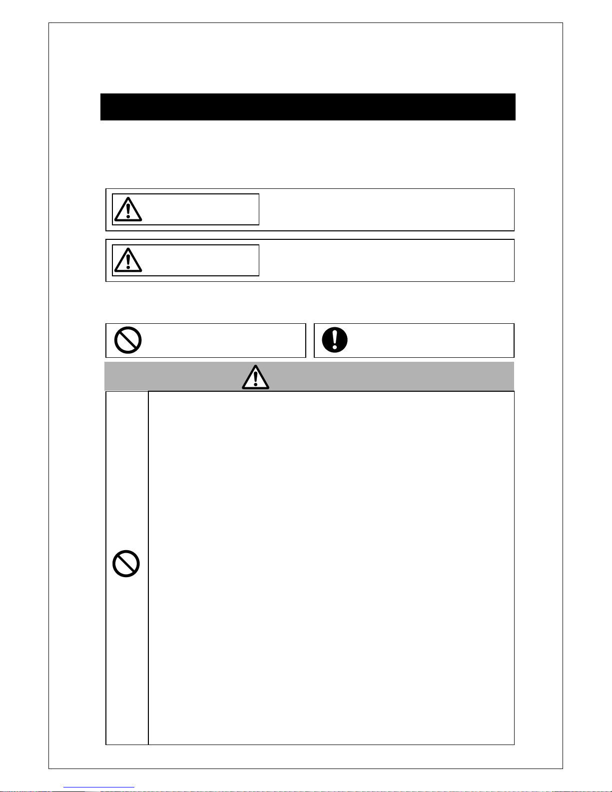
Important Safety Instructions
This chapter contains important safety instructions for preventing bodily
injury and/or property damage. You are required to follow them.
Severity of bodily injury and/or property damage, which could result
from incorrect use of the Switching Hub, are explained below.
The following symbols are used to classify and describe the type of
instructions to be observed.
This symbol is used to alert
users to what they must
Do not use power other than AC 100 - 240V.
Deviation could lead to fire, electric shock, and/or equipment
failure.
Do not handle the power cord with wet hand.
Deviation could lead to electric shock and/or equipment failure.
Do not handle this Switching Hub and connection cables during a
thunderstorm.
Deviation could lead to electric shock.
Do not disassemble and/or modify this Switching Hub.
Deviation could lead to fire, electric shock, and/or equipment
failure.
Do not damage the power cord. Do not bend too tightly, stretch,
twist, bundle with other cord, pinch, put under a heavy object,
and/or heat it.
Damaged the cord could lead to fire, short, and/or electric shock.
Do not put foreign objects (such as metal and combustible) into the
opening (such as twisted pair port, console port, SFP extension slot),
and/or do not drop them into the inside of the Switching Hub.
Deviation could lead to fire, electric shock, and/or equipment
failure.
Do not connect equipments other than
10BASE-T/100BASE-TX/1000BASE-T to twisted pair port.
Deviation could lead to fire, electric shock, and/or equipment
failure.
WARNIN
This symbol indicates safety instructions.
Deviation from these instructions could lead to
This symbol is used to alert
users to what they must
WARNIN
This symbol indicates
a potential hazard that
could result in serious injury or death.
CAUTIO

3
Do not install this Switching Hub at the location with continuous
vibration or strong shock, or at the unstable location
Deviation could lead to injury and/or equipment failure.
Do not install any module other than the separately sold SFP module
to SFP extension slot.
Deviation could lead to fire, electric shock,
and/or equipment
failure.
Do not connect any cable other than the separately sold console
cable.
Deviation could lead to fire, electric shock,
and/or equipment
failure.
Do not put this Switching Hub into fire.
Deviation could lead to explosion and/or fire.
Do not use the supplied power cord for anything other than this
product
.
WARNIN
WARNIN
CAUTION
Use the bundled power cord (AC 100 – 240V specifications).
Deviation could lead to electric shock, malfunction, and/or
equipment failure.
Unplug the power cord in case of equipment failure.
Deviation such as keeping connected for a long time, could lead to
fire.
Connect this Switching Hub to ground.
Deviation could lead to electric shock, malfunction, and/or
equipment failure.
Connect the power cord firmly to the power port.
Deviation could lead to electric fire, shock, and/or malfunction.
Handle the Switching Hub carefully so that fingers or hands may not
be damaged by twisted pair port, SFP extension slot, console port, or

4
Basic Instructions for the Use of This Product
For inspection and/or repair, consult the retailer.
Use commercial power supply from a wall socket, which is close and easily
accessible to this Switching Hub.
Unplug the power cord when installing or moving this Switching Hub.
Unplug the power cord when cleaning this Switching Hub.
Use this Switching Hub within the specifications. Deviation could lead to
malfunction.
Do not touch the metal terminal of the RJ45 connector, the modular plug of
connected twisted pair cable, or the metal terminal of the SFP extension slot.
Do not place charged objects in the proximity of them. Static electricity could
lead to equipment failure.
Do not put the modular plug of the connected twisted pair cable on objects
that can carry static charge, such as carpet. Do not place it in the proximity.
Static electricity could lead to equipment failure.
Do not put a strong shock, including dropping, to this Switching Hub.
Deviation could lead to equipment failure.
Before connecting a console cable to the console port, discharge static
electricity, for example by touching metal appliance (do not discharge by
touching this Switching Hub).
Do not store and/or use this Switching Hub in the environment with the
characteristics listed below.
(Store and/or use this Switching Hub in the environment in accordance with
the specification.)
High humidity. Possible spilled liquid (water).
Dusty. Possible static charge (such as carpet).
Under direct sunlight.
Possible condensation. High/low temperature exceeding the specifications
environment.
Strong vibration and/or strong shock.
Please use this Switching Hub in place where ambient temperature is from 0
to 40℃.
When the total power supply is 145W or less, please use the Switching Hub in
place where ambient temperature is from 0 to 45℃.
When the total power supply is 130W or less, please use the Switching Hub in
place where ambient temperature is from 0 to 50℃.
Failure to meet the above conditions may result in fire, electric shock,
breakdown, and/or malfunction. Please take notice because such cases are
out of guarantee.
Additionally, do not cover the bent hole of this Switching Hub.
Deviation could lead to high internal temperature, equipment failure and/or

5
malfunction.
When stacking Switching Hubs, leave a minimum of 20 mm space between
them is required.

6
1. Panasonic will not be liable for any damage resulting from the
operation not in accordance with this operation manual or the loss of
communications, which may or may not be caused by failure and/or
malfunction of this device.
2. The contents described in this document may be changed without prior
notice.
3. For any question, please contact the retailer where you purchased the
product.
* Brands and product names in this document are trademarks or registered
trademarks of their respective holders.

7
Table of Contents
Basic Instructions for the Use of This Product ................................................ 4
1. Product Outline ........................................................................................ 11
1.1. Features .............................................................................................. 11
1.2. Accessories .......................................................................................... 12
1.3. Part Names and Functions .................................................................. 13
1.4. LED Behavior ...................................................................................... 14
1.4.1. LED Behavior at Starting-up.......................................................... 14
1.4.2. LED Behavior while Operating ...................................................... 14
2. Installation ........................................................................................... 15
2.1. Installing in 19-inch Rack .................................................................... 15
3. Connection ............................................................................................... 16
3.1. Connecting a Twisted Pair Port .......................................................... 16
3.2. Connecting an SFP Extension Port...................................................... 17
3.3. Connecting to Power .......................................................................... 18
4. Configuration ........................................................................................... 19
4.1. Connecting via Console Port .............................................................. 19
4.2. Login ................................................................................................... 20
4.3. Basic Operations on the Screen .......................................................... 23
4.4. Main Menu ......................................................................................... 25
4.5. General Information Menu ................................................................ 27
4.6. Basic Switch Configuration ................................................................. 29
4.6.1. System Administration Configuration........................................... 30
4.6.2. System IP Address Configuration .................................................. 31
4.6.3. SNMP Configuration ..................................................................... 34
4.6.3.a SNMP Management Configuration......................................... 35
4.6.3.b. SNMP Trap Receiver Configuration ........................................ 37
4.6.3.c Enable/Disable Individual Trap ............................................... 39
4.6.4. Port Configuration Basic ............................................................... 41

8
4.6.5. Port Configuration Extend ............................................................ 44
4.6.6. System Security Configuration ...................................................... 47
4.6.6.a. Telnet Access Limitation Configuration .................................. 50
4.6.6.b. RADIUS Configuration ............................................................ 52
4.6.6.c. Syslog Transmission Configuration ......................................... 54
4.6.7. Mail Report Configuration ............................................................ 56
4.6.7.a. Report Data Configuration .................................................... 58
4.6.8. Forwarding Database ................................................................... 61
4.6.8.a. Adding or deleting MAC address ........................................... 62
4.6.8.b. Setting learning mode of MAC address ................................. 63
4.6.8.c Displaying MAC address table by port .................................... 64
4.6.8.d Displaying all MAC addresses .................................................. 66
4.6.8.e Displaying MAC address table by VLAN .................................. 67
4.6.9. Time Configuration ....................................................................... 69
4.6.10. ARP Table Configuration ............................................................ 71
4.7. Advanced Switch Configuration ......................................................... 73
4.7.1. VLAN Management ...................................................................... 75
4.7.1.a. Special Features ...................................................................... 75
4.7.1.b. VLAN Management Menu ...................................................... 76
4.7.1.c. VLAN Creation Menu .............................................................. 80
4.7.1.d. VLAN Modification Menu ....................................................... 82
4.7.1.e. VLAN Port Configuration Menu ............................................. 84
4.7.2. Link Aggregation .......................................................................... 86
4.7.2.a About Link aggregation .......................................................... 86
4.7.2.b. Trunk Configuration ............................................................... 88
4.7.2.c. Set Port Priority for LACP ....................................................... 91
4.7.2.d. LACP Group Status ................................................................. 93
4.7.3. Port Monitoring Configuration ..................................................... 96
4.7.4. Multiple Spanning Tree Configuration ......................................... 98
4.7.4.a. CIST (MST Instance 0) Configuration.................................... 102
4.7.4.b CIST Basic Port Configuration ............................................... 104
4.7.4.c. CIST Advanced Port Configuration ....................................... 107
4.7.4.d. MST Instance Configuration ................................................. 110
4.7.4.e. MST Instance Advanced Configuration ................................ 112
4.7.4.f. MST Instance Port Configuration .......................................... 114
4.7.4.g MST Instance Topology Information ..................................... 117

9
4.7.4.h. Designated Topology Information ....................................... 119
4.7.4.i. Regional Topology Information ............................................ 120
4.7.5. Access Control Configuration Menu ........................................... 122
4.7.5.a. Classifier Configuration Menu .............................................. 123
4.7.5.b. Create Classifier Configuration Menu .................................. 125
4.7.5.c. Classifier Configuration Menu .............................................. 129
4.7.5.d. Show Detailed Entries Information Menu ............................ 131
4.7.5.e. In-Profile Action Configuration Menu .................................. 133
4.7.5.f. Create In-Profile Action Menu .............................................. 135
4.7.5.g. Out-Profile Action Configuration Menu ............................... 137
4.7.5.h. Create Out-Profile Action Menu ........................................... 139
4.7.5.i. Port List Configuration Menu ................................................ 141
4.7.5.j. Policy Configuration Menu ................................................... 143
4.7.5.k. Create Policy Configuration Menu ....................................... 145
4.7.6. Quality of Service Configuration ................................................. 147
4.7.6.a. Traffic Class Configuration ................................................... 148
4.7.6.b. Configuration of Scheduling Method ................................... 149
4.7.7. Egress Rate Limiting Configuration Menu .................................. 150
4.7.8. Storm Control Configuration Menu ............................................ 151
4.7.9. 802.1x Access Control Configuration .......................................... 154
4.7.9.a. IEEE 802.1X Port Based Access Control Configuration ......... 155
4.7.9.b. MAC Based Access Control Configuration............................ 159
4.7.9.c. Force Authorized MAC Configuration Menu ....................... 163
4.7.9.d. Guest/Default VLAN Configuration Menu ........................... 165
4.7.9.e. IEEE 802.1X Statistics Menu ................................................. 167
4.7.9.f. EAP-Request Configuration Menu ........................................ 172
4.7.10. IGMP Snooping Configuration .................................................. 177
4.7.10.a. Set Leave Mode Menu ........................................................ 180
4.7.10.b. VLAN Filter Configuration ................................................... 182
4.7.10.c. Router Port Table Configuration ......................................... 183
4.7.10.d. Set Querier Configuration Menu ........................................ 184
4.7.11. Power Over Ethernet Configuration ......................................... 186
4.7.11.a. PoE Port Configuration Menu ............................................. 187
4.7.11.b. PoE Global Configuration .................................................... 189
4.7.12. Ring Redundant Protocol Configuration .................................. 191
4.7.12.a. RRP Domain Creation Menu ............................................... 194

10
4.7.12.b. RRP Domain Modification Menu ........................................ 196
4.7.12.c. RRP Domain information Menu .......................................... 198
4.8. Statistics ............................................................................................ 200
4.9. Switch Tools Configuration .............................................................. 205
4.9.1. TFTP Software Upgrade .............................................................. 206
4.9.2. Configuration File Upload/Download ........................................ 209
4.9.3. System Reboot ............................................................................ 211
4.9.4. Exception Handler ....................................................................... 213
4.9.5. Ping Execution ............................................................................ 214
4.9.6. System Log .................................................................................. 217
4.7.6.a. Enable/Disable Individual System Log Menu........................ 220
4.9.7. Watch Dog Timer Menu.............................................................. 222
4.10. Save Configuration to Flash ............................................................ 223
4.11. Command Line Interface (CLI) ........................................................ 224
4.12. Logout ............................................................................................ 225
Appendix A. .............................................................................. Specifications
226
Appendix B. Procedures for Console Port Configuration using Windows
HyperTerminal ........................................................................................... 230
Appendix C. Easy IP Address Setup Function............................................. 231
Troubleshooting ......................................................................................... 232
After-sales Service ...................................................................................... 234

11
11.. PPrroodduucctt OOuuttlliinnee
Switch-M24PWR is an Ethernet Switching Hub with management function
having 24 ports of 10/100BASE-TX and two pairs of 10/100/1000BASE-T
port and SFP extension slot, one of which is selectable.
Ports 1 to 24 support IEEE802.3af compatible PoE power supply function.
11..11.. FFeeaattuurreess
Ports 1 to 24 are 10/100BASE-TX ports corresponding to auto
negotiation.
Ports 25 and 26 can be used as a 10/100/1000BASE-T port
corresponding to auto negotiation or an SFP extension slot exclusively.
Ports 1 to 24 can supply power conforming with IEEE802.3af. Supplying
power up to 15.4W per port, and up to 175W in total is possible.
All twisted pair ports support straight/cross cable auto sensing function.
Simply connect devices with straight cables, whether it is a terminal or a
network device.
(This function does not work if the port communication configuration is
set at Fixed or Link Aggregation. Ports 1 to 24 are set at MDI-X.
(default))
SSH/Telnet allows remote configuration changes and verifications of
the Switching Hub.
Remotely configure the PoE settings for each port (Ports 1 to 24).
Embedded power saving mode detects the connection status
automatically and saves power consumption to minimum.
VLAN function allows free grouping of up to 256 VLANs.
The IEEE802.1s Multiple Spanning Tree Protocol is supported, allowing
to build a system with redundancy.
The IEEE802.1p compatible QoS function is supported.
The IEEE802.1X compatible user authentication function
(EAP-MD5/TLS/PEAP) is supported.
The IEEE 802.3ad compatible tranking function is supported, allowing
to aggregate the ports up to 8 ports.

12
11..22.. AAcccceessssoorriieess
Please be sure to confirm the content.
Please contact our distributor if any of the contents are insufficient.
Quantity
Installation Guide…………………………………………………………………… 1
CD-ROM (PDF version of Operating Instuctions)…………………..… 1
Mounting bracket (for 19-inch rack)………………………………………. 2
Screws (for 19-inch rack)……………………………………………………. 4
Screws (for fixing the main unit and the mounting bracket)……… 8
Rubber foot…………………………………………………………………………. 4
Power cord (CEE7/7)(*)…………………………………………………… 1
(*) The attached power cord iss dedicated for AC 100 – 240V use.

13
11..33.. PPaarrtt NNaammeess aanndd FFuunnccttiioonnss
Fig. 1-1 Switch-M24PWR
Fig. 1-2 Front LED Magnified View
Power port
RJ45 console
port
Back panel
Front panel
10/100/1000BASE-T port
10/100BASE-TX port
SFP extension slot
Power cord hook block
Ground terminal
14
11..44.. LLEEDD BBeehhaavviioorr
11..44..11.. LLEEDD BBeehhaavviioorr aatt SSttaarrttiinngg--uupp
Upon turning this Switching Hub on, all LEDs (PWR, STATUS, PoE and
LINK/ACT for each port) light up. Then, the hardware self diagnosis is
executed. Upon finishing the diagnosis, PWR and STATUS LEDs light in solid
green. The Switching Hub is working as a Switching Hub.
Power LED and Self-diagnosis LED
LED
Behavior
Description
Power LED (PWR)
Solid green
Power On
Off
Power Off
Self-diagnosis LED
(STATUS)
Solid green
System is operating normally.
Solid orange
System is starting up.
Flashing orange
System fault.
Off
Power Off
11..44..22.. LLEEDD BBeehhaavviioorr wwhhiillee OOppeerraattiinngg
This Switching Hub has a set of LEDs for each port. These LEDs indicate the
operation status of each port.
10/100BASE-TX port LEDs (Ports 1 to 24)
LED
Label in front
Behavior
Description
PoE LED
PoE
Solid green
Supplying power.
Flashing orange
Overloading.
Off
Not supplying power or no
device connected.
Link/
Transmission
LED
LINK/ACT.
Solid green
100 Mbps link established.
Solid orange
10 Mbps link established.
Flashing green
Transmitting packets at 100
Mbps.
Flashing orange Transmitting packets at 10
Mbps.
Off
No device connected.
1000BASE-T/SFP extension slot LED (shared) (Ports 25 and 26)
LED
Label in front
Behavior
Description
Speed mode
LED (GIGA)
GIGA
Solid green
1 Gbps link established.
Off
Connected at 10/100 Mbps or
no device connected.
Speed mode
LED (100)
100
Solid green
100 Mbps link established.
Off
Connected at 10 Mbps or no
device connected.
Link/
Transmission
LED
LINK/ACT.
Solid green
100 Mbps link established.
Flashing green
Transmitting packets at 100
Mbps.
Off No device connected.
15
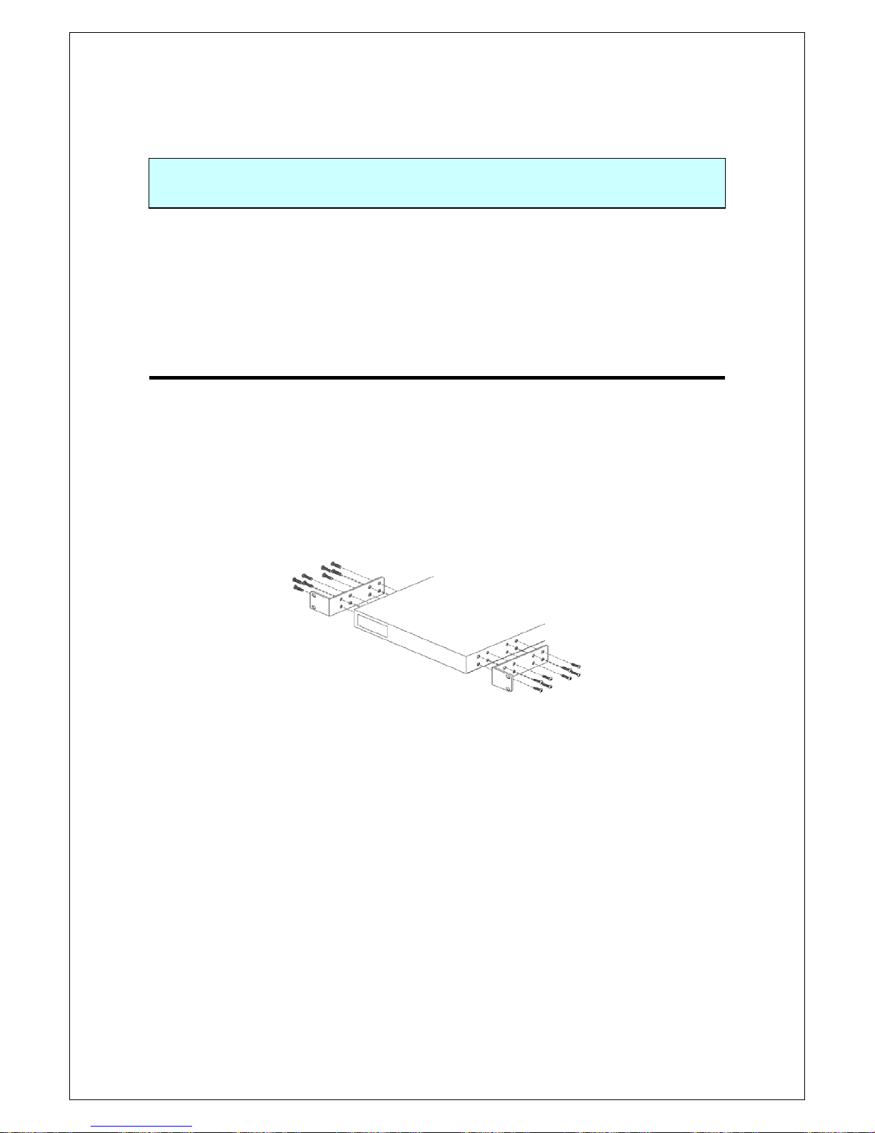
22.. IInnssttaallllaattiioonn
Switch-M24PWR can be installed in a 19-inch rack.
Mounting brackets and screws are included in the package, requiring no
separate purchase.
22..11.. IInnssttaalllliinngg iinn 1199--iinncchh RRaacckk
Two mounting brackets and eight screws (for fixing the main unit and the
mounting bracket) are included in the package. Each side of the main unit
has four screw holes. Fix the mounting brackets and the main unit by
tightening four screws each.
Then, by using four screws (for 19-inch rack) included in this Switching Hub
or procured for the lack, firmly mount the main unit in the rack.
Fig. 2-1 Installing in 19-inch Rack

16
33.. CCoonnnneeccttiioonn
33..11.. CCoonnnneeccttiinngg aa TTwwiisstteedd PPaaiirr PPoorrtt
Connection Cable
Use a CAT5-compliant straight cable (twisted pair) with 8P8C RJ45 modular
plugs.
Network Configuration
Fig. 3-1 Connection example
The length of the cable connecting this Switching Hub and a device must be
100 m or shorter. When a terminal or a LAN device with auto negotiation
function is connected to this Switching Hub, the port is automatically
configured at the highest performance mode. When a terminal or a LAN
device without auto negotiation function is connected to this Switching
Hub, this Switching Hub automatically determines and sets the
communication speed; however, the full-duplex/half-duplex configuration is
set at half-duplex because the full-duplex/half-duplex capability cannot be
determined. When connecting a terminal or a LAN device without auto
negotiation function, a fixed-mode port configuration needs to be set. For
detailed configuration procedure, refer to 4.6.4.
Note:
If a fixed-mode port configuration mode is set, Auto-MDI/MDI-X
function does not work. Therefore, use a cross cable to connect them.
100m or
100m or
100m or shorter

17
33..22.. CCoonnnneeccttiinngg aann SSFFPP EExxtteennssiioonn PPoorrtt
Fig. 3-2 Optical fiber cable connection example
Plugging an SFP module (optional) into an SFP extension port enables a
optical fiber connection. The SFP extension port shares the port with the
twisted pair port. The twisted pair port is enabled; however, the SFP
extension port is automatically enabled when a fiber optical link is
established.
Connect this Switching Hub's TX port to the RX port of the connected
device and this Switching Hub's RX port to the TX port of the connected
device.
1000BASE-SX: 500 m or shorter/1000BASE-LX: 10 km or shorter
100m or
100m or

18
33..33.. CCoonnnneeccttiinngg ttoo PPoowweerr
Connect the supplied power cord to the power port of this Switching Hub
and connect the other end into an electric outlet. This Switching Hub
operate at AC 100 to 240 V (50/60 Hz). This Switching Hub does not have a
power ON/OFF switch. Plugging the power cord turns on this Switching
Hub's power and it starts operating. To power off, unplug the power cord
from the electric outlet.

19
44.. CCoonnffiigguurraattiioonn
Upon power ON, this Switching Hub starts working as a Switching Hub. To
use the SNMP functions and other functions, you need to configure the
Switching Hub by using the console or Telnet.
In this chapter, the configuration of this Switching Hub is explained in
detail.
Note: To access this Switching Hub via Telnet, this Switching Hub must have
an IP address. Therefore, before accessing this Switching Hub via
Telnet, configure an IP address by accessing this Switching Hub via
console. For details on configuring an IP address, refer to 4.6.2.
44..11.. CCoonnnneeccttiinngg vviiaa CCoonnssoollee PPoorrtt
Console connection requires a DEC VT100-compatible asynchronous
terminal, or a terminal capable of running a VT100-compatible terminal
emulator, such as HyperTerminal on Windows XP or older. Connect a
terminal of this kind to the RJ45 console port of this Switching Hub.
Configure the communication mode for the asynchronous terminal as
follows:
Transmission mode: RS-232C (ITU-TS V.24 compliant)
Emulation mode: VT100
Transmission speed: 9600 bps
Data length: 8 bits
Stop bit: 1 bit
Parity control: None
Flow control: None
If you are using a Windows machine, refer to "Procedures for Console Port
Configuration using Windows HyperTerminal."

20
44..22.. LLooggiinn
Upon connecting, a login window, similar to
Fig. 4-2-1
, is displayed. If no
similar window is displayed, make sure the transmission mode of console is
correct or hit the enter key.
Fig. 4-2-1 Login screen (Console)
=============================================================================
PN23249K/PN23249A Local Management System Version 2.0.0.xx
MAC Address: 00:C0:8F:xx:xx:xx
==============================================================================
Login Menu
Login:

21
If you access the Switching Hub via Telnet, the screen displays "Remote
Management System" on the top, similar to
Fig. 4-2-2
.
Fig. 4-2-2 Login screen (Telnet)
=============================================================================
PN23249K/PN23249A Remote Management System Version 2.0.0.xx
MAC Address: 00:C0:8F:xx:xx:xx
==============================================================================
Login Menu
Login:

22
On the login screen, similar to
Fig. 4-2-1
or
Fig. 4-2-2
, enter the login name.
The Switching Hub's default login name is set to "manager." Enter
"manager" and press the Return key. Then, you need to enter a password,
as
Fig. 4-2-3
displays. The Switching Hub's default password is the same as
the login name ("manager"). Enter the password correctly and press the
Return key.
Fig. 4-2-3 Entering password
Both the login name and password can be changed. For the detailed
change procedure, refer to
4.6.6.
Note: Up to four users can access the Switching Hub concurrently via Telnet.
=============================================================================
PN23249K/PN23249A Local Management System Version 2.0.0.xx
MAC Address: 00:C0:8F:xx:xx:xx
==============================================================================
Login Menu
Login: manager
Password: *******
23
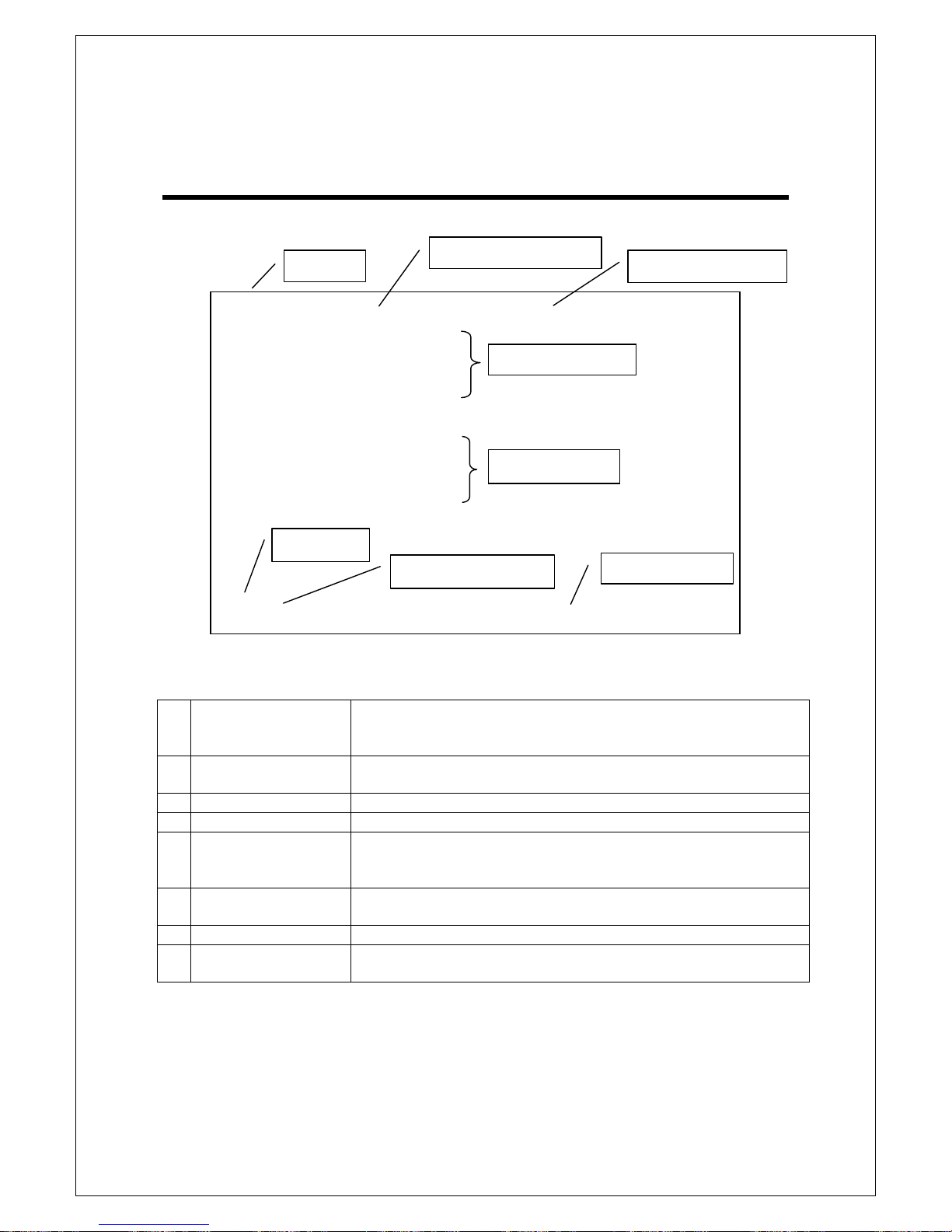
44..33.. BBaassiicc OOppeerraattiioonnss oonn tthhee SSccrreeeenn
The console screen of the Switching Hub is organized as follows:
Fig. 4-3-1 Screen structure
Screen Description
1.
Title
The title of this screen. Displays "Local Management System"
while being accessed via console. Displays "Remote
Management System" while being accessed via Telnet.
2.
Previous menu
name
Displays the name of the parent menu. Entering the "Q"
command opens the parent menu screen.
3.
Current menu name
Displays the name of the current screen.
4.
Configuration
Displays the current configuration.
5.
Command
Displays the commands available on this screen. Available
commands differ on each screen. Select a command from the
list.
6.
Prompt
Changes as you enter a command, indicating what you need to
enter next. Follow this instruction.
7.
Command entry line
Enter a command or settings.
8.
Explanation
Displays the explanation and/or status of this screen. Also,
displays an entry error message if applicable.
All operations on this screen are done by entering letters. Using a cursor or
other operations are not available. Available commands (letters) differ on
each screen. They are shown in the command section. One letter of each
command is enclosed in square brackets ([]). Enter this letter to enter the
PN23249K/PN23249A Local Management System
Basic Switch Configuration -> System Admin. Configuration Menu
Description: Switch-M24PWR
Object ID: 1.3.6.1.4.1.396.5.4.1.19
Name:
Location:
Contact:
-------------------------------- <COMMAND> -----------------------------------
Set System [N]ame
Set System [L]ocation
Set System [C]ontact Information
[Q]uit to previous menu
Command>
Enter the character in square brackets to select option
6. Prompt
7. Command entry
4. Configuration
5. Command
8. Explanation
2. Previous menu
1. Title
3. Current menu

24
command. If you enter a command or setting not available, an error
message is shown in the explanation field.
25
44..44.. MMaaiinn MMeennuu
After the login process, the main menu, similar to
Fig. 4-4-1
, appears.
This Switching Hub has a main menu and multiple sub-menus. These menus
has a tree structure, with the main menu as its root. To move to a sub-menu,
enter a command letter. To return to the previous menu, press the "Q"
command. The second line from the top displays the current menu name.
Fig. 4-4-1 Main Menu
Screen Description
General information
Displays this Switching Hub's hardware, firmware information and
address settings.
Basic Switch
Configuration…
Configures this Switching Hub's basic functions (such as IP address,
SNMP and port configuration).
Advanced Switch
Configuration…
Configures this Switching Hub's advanced functions (such as VLAN,
link aggregation, spanning tree, ACL, QoS, IEEE802.1X
authentication, IGMP snooping, and PoE).
Statistics
Displays this Switching Hub's statistical information.
Switch Tools
Configuration
Set this Switching Hub's additional tools (such as firmware update,
saving/reading settings, Ping, and system log).
Save Configuration
to Flash
Saves this Switching Hub's settings into its internal flash memory.
Run CLI
Switches to a command line interface.
Quit
Logouts and returns to the login screen.
PN23249K/PN23249A Local Management System
Main Menu
[G]eneral Information
[B]asic Switch Configuration...
[A]dvanced Switch Configuration...
[S]tatistics
Switch [T]ools Configuration...
Save Configuration to [F]lash
Run [C]LI
[Q]uit
Command>
Enter the character in square brackets to select option

26

27
44..55.. GGeenneerraall IInnffoorrmmaattiioonn MMeennuu
On the Main Menu, pressing "G" opens the General Information Menu, as
shown in
Fig. 4-5-1
. This screen displays this Switching Hub's basic
information. You cannot edit shown information on this screen.
Fig. 4-5-1 General Information Menu
PN23249K/PN23249A Local Management System
Main Menu -> General Information
System up for: 000day(s), 00hr(s), 00min(s), 00sec(s)
Boot / Runtime Code Version: 1.0.0.xx / 2.0.0.xx
Hardware Information
Version: Version1
CPU Utilization: 0.00 %
DRAM / Flash Size: 64MB / 8MB
DRAM User Area Size: Free: 21989288 bytes / Total: 36175872 bytes
System Fan Status: Good
System Temperature: CPU/39 ,System/36 degree(s) Celsius
Administration Information
Switch Name:
Switch Location:
Switch Contact:
System Address Information
MAC Address: 00:C0:8F:xx:xx:xx
IP Address: 192.168.2.13
Subnet Mask: 255.255.255.0
Default Gateway: 192.168.2.254
DHCP Mode: Disabled
Press any key to continue...

28
Screen Description
System up for
Displays the cumulative time since the power on of this Switching Hub.
Boot /
Runtime Code
Version
Displays this Switching Hub's firmware version.
The left side displays the Boot Code and the right side displays the
Runtime Code.
("TFTP Software Upgrade" in 4.9.1 is about Runtime Code update.)
Hardware
Information
Displays the hardware information.
Version
Displays the hardware version information.
CPU
Utilization
Displays the CPU utilization.
DRAM / Flash
Size
Displays the sizes of installed DRAM and FLASH
memory.
DRAM User
Area Size
Displays the sizes of the user area memory and unused
memory.
System
Temperature
Displays the internal temperatures of the Switching
Hub.
The sensors measure the temperature of CPU and
system.
Administration
Information
Items shown here are configured in accordance with "4.6.1 System
Administration Configuration."
Switch Name Displays the Switching Hub name. The factory default
setting is blank. For configuration details, refer to 4.6.1.
Switch
Location
Displays the Switching Hub's location. The factory
default setting is blank. For configuration details, refer
to 4.6.1.
Switch
Contact
Displays the contact information. The factory default
setting is blank. For configuration details, refer to 4.6.1.
System
Address
Information
Items shown here are configured in accordance with "4.6.2 System IP
Configuration."
MAC Address
Displays the MAC address of this Switching Hub. This
value is uniquely assigned to each device and cannot be
changed.
IP Address
Displays the Switching Hub's current IP address. 0.0.0.0
is the factory default setting. For configuration details,
refer to 4.6.2.
Subnet Mask Displays the Switching Hub's current subnet mask.
0.0.0.0 is the factory default setting. For configuration
details, refer to 4.6.2.
Default
Gateway
Displays the IP address of the router for the default
gateway. 0.0.0.0 is the factory default setting. For
configuration details, refer to 4.6.2.
DHCP Mode:
Displays whether to get an IP address using DHCP. For
configuration details, refer to 4.6.2.

29
44..66.. BBaassiicc SSwwiittcchh CCoonnffiigguurraattiioonn
On the Main Menu, pressing "B" opens the Basic Switch Configuration
Menu, as shown in
Fig. 4-6-1
. On this screen, you can configure basic
configuration settings, such as IP address, SNMP, and ports.
Fig. 4-6-1 Basic Switch Configuration Menu
Screen Description
System Administration
Configuration
Displays the administrative information, such as Switching Hub
name, location and contact information.
System IP Configuration
Configures the IP-address-related network information.
SNMP Configuration
Configures SNMP-related settings.
Port Configuration Basic
Configures basic port settings.
Port Configuration
Extend
Configures extended port settings, such as port name.
System Security
Configuration
Configures the security settings, such as access limitation for
this Switching Hub.
Mail Report
Configuration
Configures the E-mail-report transmission settings.
Forwarding Database
Displays the MAC address table.
Time Configuration Configures the time settings, such as the SNTP-based time
synchronization function and manual mode settings.
ARP Table
Displays the ARP table.
Quit to previous menu
Returns to the main menu.
PN23249K/PN23249A Local Management System
Main Menu -> Basic Switch Configuration Menu
System [A]dministration Configuration
System [I]P Configuration
S[N]MP Configuration
[P]ort Configuration Basic
Port Configuration [E]xtend
[S]ystem Security Configuration
[M]ail Report Configuration Menu
[F]orwarding Database
[T]ime Configuration
A[R]P Table
[Q]uit to previous menu
Command>
Enter the character in square brackets to select option

30
44..66..11.. SSyysstteemm AAddmmiinniissttrraattiioonn CCoonnffiigguurraattiioon
n
On the Basic Switch Configuration Menu, pressing "A" opens the System
Administration Configuration Menu, as shown in
Fig. 4-6-2
. On this screen,
you can set administrative information, such as device name.
Fig. 4-6-2 System Administration Configuration
Screen Description
Description:
Displays the system information. This item is not editable.
Object ID:
Displays the ID, corresponding to MIB. This item is not editable.
Name:
Displays the system name. The factory default setting is blank.
Location:
Displays the device installation location. The factory default setting is
blank.
Contact:
Displays the contact information. The factory default setting is blank.
Available commands are listed below.
N
Set/edit the system name.
Press "N." The command prompt changes to "Enter system name>." Enter a
Switching Hub name in 50 characters or less.
L
Set/edit the device installation location information.
Press "L." The command prompt changes to "Enter system location>." Enter a
Switching Hub location in 50 characters or less.
C
Set/edit the contact information.
Press "C." The command prompt changes to "Enter system contact>." Enter
contact information in 50 characters or less.
Q
Return to the previous menu.
PN23249K/PN23249A Local Management System
Basic Switch Configuration -> System Admin. Configuration Menu
Description: Switch-M24PWR
Object ID: 1.3.6.1.4.1.396.5.4.1.19
Name:
Location:
Contact:
-------------------------------- <COMMAND> -----------------------------------
Set System [N]ame
Set System [L]ocation
Set System [C]ontact Information
[Q]uit to previous menu
Command>
Enter the character in square brackets to select option
 Loading...