

Page 1
For speed control of 3-phase induction motor
Inverter M1X Series
Operating Instructions
Be sure to provide the customer with a copy of this manual.
● Thank you for purchasing a Panasonic Inverter.
● Be sure to read the instructions thoroughly before attempting to operate the
inverter. After reading, be sure to keep in a safe place for future reference.
Industrial and Appliance Motor Division, Motor Company
Matsushita Electric Industrial Co., Ltd
Page 2

CONTENTS
Before use
Preparation and
adjustment
Safety Precaution
Introduction
● When unpacking・・・・・・・・・・・・・8
● Inverter model check ・・・・・・・・・8
System Configuration
●Wiring general view・・・・・・・・・11
●Wiring ・・・・・・・・・・・・・・・・・・・・・12
●Terminal function ・・・・・・・・・・・13
●Precautions when wiring ・・・・15
・・・・・・・・・・・・8
・・・・・・・4
・11
If necessary
Application
Specifications
Protective Function
●Protective functions・・・・・・・・・18
●Method of resetting trip・・・・・・20
Detailed Explanation
of Parameters
●Parameter functions ・・・・・・・・23
Specifications
Outer Dimensions
・・・・・・・・37
・・・ 18
・・23
・・・・39
‑2‑
Page 3

CONTENTS
・・・・・・・・・・・
Precautions
・・・・・・・・・・・ 9
・・・・・・・・・・・・・・・・・・・・・・
Installation
・・・・・・・・・・
・・・・・・・・・・10
・・・・・・・・・・・・・・・・・・・・
●
Note the following
precautions in order to use
the inverter properly
・・・・・・・・・・・・9 ●
Parameter Setting
●
How to set
Maintenance/
・・・・・・・・・・・・・・・・16
・・・・・・・・
・・・・・・・・ 21
・・・・・・・・・・・・・・・・
・・・・
・・・・16
・・・・・・・・
21
2121
・・・・・・・・・・・・・・・・・
Inverter
・・・・・・・・・・・・・・・・・ 10
・・・・・・・・・・・・・・・・・・・・・・・・・・・・・・・・・・
Troubleshooting
・・・・・
・・・・・22
・・・・・・・・・・
22
2222
Before use
準備と調整
Adjustment
Preparation and
Inspection
Parameter Setting
●
Parameter overview
●
Parameter configuration
and list of parameters
・・・
・・・ 41
・・・・・・
・・・・・・・・41
41
4141
・・・・41
●
Inspection to determine
cause of problem
・・・・22
If necessary
Application
tions
Specifica-
‑3‑
Page 4
Safety Precautions
!
!!
!
!
!!
!
!
!!
!
!!!!
Precautions that must be heeded in order to protect the user and others from harm and
prevent property loss or damage are as follows:
■■■■
The extent of injury or damage that could be suffered by improper
use contrary to directions is ranked and explained as follows:
DANGER
CAUTION
Items labeled as CAUTION could be connected with core serious consequences,
depending upon the circumstances. In any case, these instr uctions are ex tremely import ant
and should be observed in all cases.
■■■■
Installation
Situation involving danger which could result in death or serious
injury if equipment is handled incorrectly.
Situation involving danger which could result in medium to light
injury, or property damage if equipment is handled incorrectly.
CAUTION
● Install on non-combustible material such as metal.
Failure to do so could resu lt in fire.
● Do not locate near combustibles.
Doing so could result in fire.
● Do not carry by the front case when moving the inverter.
Doing so is dangerous and could result in injury if dropped.
● Do not allow foreign material such as metal chips to get inside the inverter.
Doing so could result in fire.
● Be sure to install on a base capable of supporting the inverter’s weight in
accordance with the directions giving in the instruction manual.
Doing so is dangerous and could result in injury if dropped.
‑4‑
Page 5

Safety Precautions
!
!!
!
!
!!
!
■■■■
Wiring
DANGER
●
Make sure the power is cut off before handling wiring.
Failure to do so could result in electrical shock or fire.
● Be sure to install a no-fuse breaker (NFB).
Failure to do so could resu lt in fire.
● Be sure to ground the GND terminal.
Failure to do so could result in electrical shock or fire.
● Have wiring work done by an electrician.
Failure to do so could result in electrical shock or fire.
● Be sure to install the inverter before wiring.
Failure to do so could result in electrical shock or fire.
CAUTION
● Do not connect the AC power source with the output terminals (U/L1, V/L2, W/L3).
Doing so could result in injury or fire.
● Make sure the voltage of the AC power source agrees with the rated voltage of the
inverter.
If not, it could result in injury or fire.
‑5‑
Page 6
Safety Precautions
!
!!
!
!
!!
!
■■■■
Operation
DANGER
● Be sure to mount the case and cover before turning the power on. Never remove
the case or cover while the inverter is receiving power.
Failure to mount or removing the case/cover could result in electric shock.
● The operator should secure the area before turning the power on or off.
Failure to do so could result in injury.
● Never operate the switches with wet hands.
Doing so could result in electric shock.
● Never touch the terminals of the inverter when it is charged with power, even when
it is not running. Doing so could result in electric shock.
● If the retry function is selected, the inverter could unexpectedly start operating
again if tripped. Do not approach the inverter in the condition.
Doing so could result in injury.
● If trip reset is carried out with the operate signal ON, the inverter could
unexpectedly start operating again. Do not approach the inverter in the condition.
Doing so could result in injury.
CAUTION
● The radiator and regenerative resistor become ve ry hot.
Touching these parts could result in skin burning injury.
● It is very easy to set speed from "low" to "high" by an inverter. Set the operating
speed so that it the motor and machine tolerance is not exceeded.
Failure to do so could result in injury.
‑6‑
Page 7
Safety Precautions
!
!!
!
!
!!
!
■■■■
Maintenance/inspection
DANGER
● Wait for at least 5 minutes after turning off the power to perform inspections.
Failure to do so could result in electric shock.
● Maintenance and inspection should not be performed by anyone except a
specialist.
The repairman should remove all metallic objects (watch, rings, etc.) before
performing maintenance or inspection.
Use only insulated tools when performing maintenance or inspection.
Failure to do so could resu lt in electric shock or injury.
■■■■
Other
DANGER
● Absolutely DO NOT modify the inverter in any way.
Doing so could result in electric shock, injury or fire.
GENERAL PRECAUTIONS
The diagrams given in this instruction manual may show the cases, covers or safety
breakers removed in order to show details.
When operating, be sure to return the cases, covers or safety breakers and operate
as specified in the manual.
‑7‑
Page 8
Introduction
When unpacking
・Is the model correct?
・Was the equipment damaged in transport?
If there is anything wrong with the equipment, contact your Panasonic
dealer.
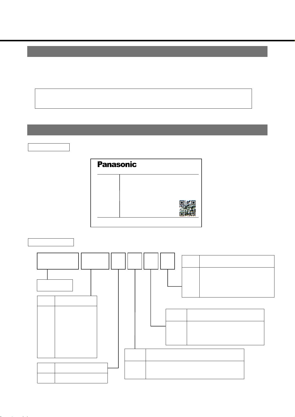
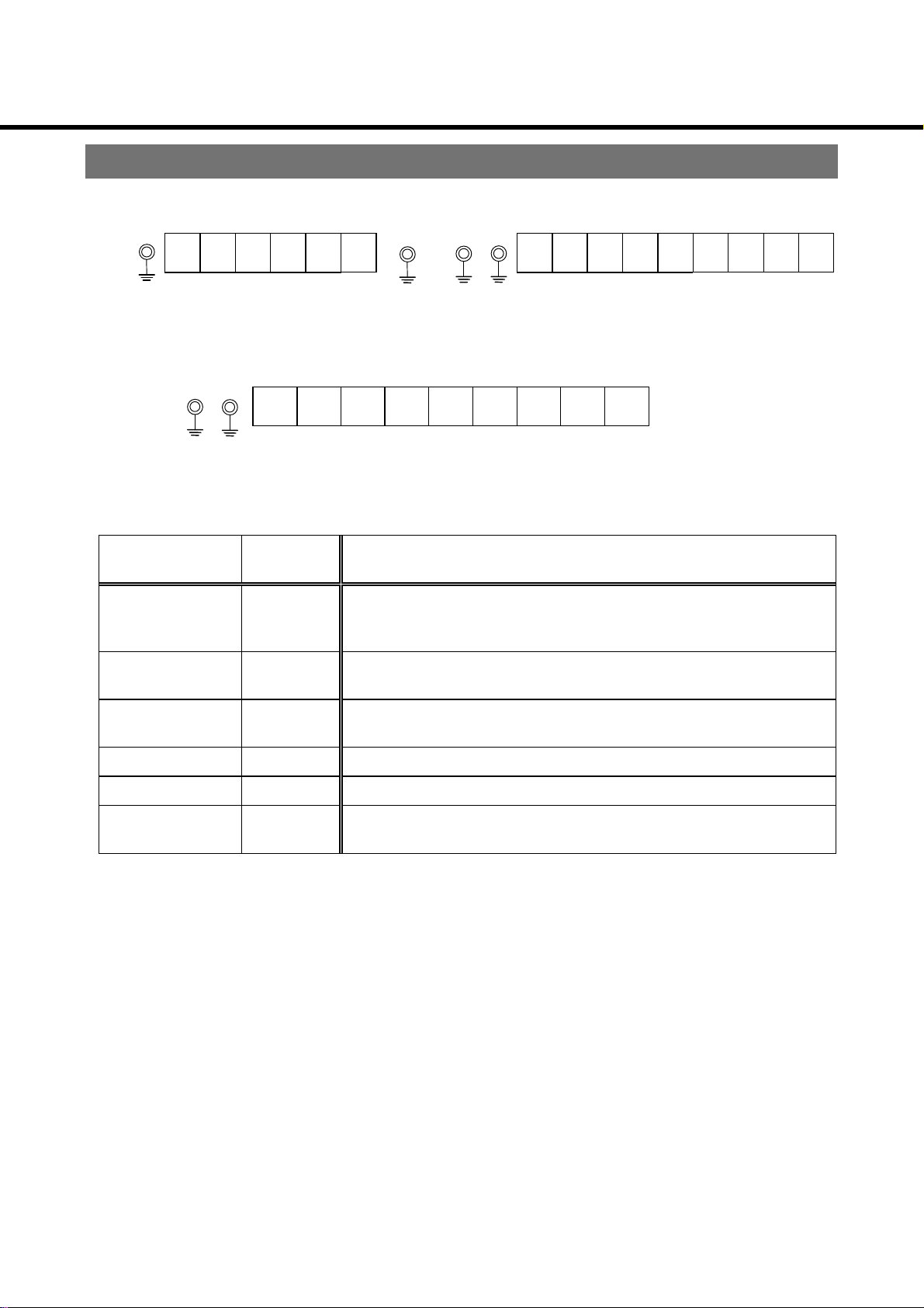
Inverter model check
Nameplate
M1SO83CSA
M1SO83CSA
M1SO83CSAM1SO83CSA
ModelNo
Power 15kW
Input 3PHAC380〜460V50/60Hz
37A
Output 3PHAC380〜460V0〜400Hz
32A
MIXA54ASA
Product No.
Series name
Code Motor capacity
08
15
22
37
55
75
A1
A5
0.75 kW
1.5 kW
2.2 kW
3.7 kW
5.5 kW
7.5 kW
11 kW
15 kW
Ser.No. 9903012
MatsushitaElectricIndustrialCo.,Ltd.MadeinJapan
Code Interface specs.
A
C
Code Operation panel specs.
S
V
N
Code Regenerative brake specs.
Without set volume (standard)
Without communicatio n functi on/
standard type (NPN logic)
With communication fun ction/
standard type (NPN logic)
With speed-set volume
Blank cover
A
Code Volt age class
4 3-phase 400 V
Consult your Panasonic de aler regarding products with communicat i on f unctions.
Without regenerative brake circuit
B
With regenerative brake circuit (bui lt -in)
‑8‑
Page 9

Precautions
Note the following precautions in order to use the inverter properly.
1. Arrange for the power source capacity to be between 1.5 to 500kVA the inverter's
capacity. An excessively high peak current may flow to the power input circuit, and
damage the converter section if the wiring length is short with a power source
exceeding 500kVA, or the phase-advancing capacitor is switched on the power
source side. In this case, pr ovi de indiv idual pow er factor -enha ncing AC reactors that
match the inverter's capacity on the inverter input side.
2. Do not connect the phase- adv ancing cap acitor to th e outp ut sid e of th e inver ter. Doing
so could result in damage to the phase-advancing capacitor.
3. Do not provide a magnetic contactor between the inverter and motor. To run or turn
the motor on/off, use the RUN switch on the control panel or the control input terminal.
Avoid frequently turning the magnetic contactor, provided on the power source, on
and off.
4. Operating the motor by the inverter could increase leakage current and trip the earth
leakage breaker. In this case, use earth leakage bre akers d esig ned for high freque ncy
for this system and other systems.
5. Take the following precautions if using a built-in electronic thermal relay contained in
the inverter:
・Check the rated current of your 3-phase induction m otor, and set the appropriate
electronic thermal value.
・Use one motor for each inverter.
6. in using the inverter to dri ve multi ple m otors co nnecte d in parall el, s elect an i nv erter of
a capacity that does not exceed the total rated current of the inverter. When
calculating by total output of the motor, the inverter’s rated current may be exceeded,
depending on the type of motor.
7. The total wiring l ength betw een inv erter a nd mo tor sh ould not exceed 30 m eter s. I f th e
wiring is to be longer than this, you should provide a reactor, etc., between inverter
and motor.
8. Install the inverter securely to avoid injuries in the case of an earthquake.
9. Before running the inverter following an earthquake, check installation of the inverter
and motor and make sure they are safe to operate.
‑9‑
Page 10
Installation
Install the inverter properly to prevent equipment failure or accidents.
Inverter
Installation location
① Install the inverter indoors in a place not exposed to rain or direct sunlight. The inverter
is not waterproof.
② Install in a place not exposed to c orrosi ve/flamm abl e g ases, gri nding fl ui d, oil mist, metal
powder or chips.
③ Place with adequate ventilation, w hic h is not exposed to excessive humidity, dirt or dust.
④ Place not subject to vibration.
Environmental conditions
Item Conditions
−10 〜 50℃ (Must not freeze)
Ambient temperature
Ambient humidity
When ambie nt temperature is higher than +40℃, the air
apron and the linear rubber apron should be disassembled
Max. 90%RH(Must be no condensation)
Storage temperature
Storage humidity
−20℃ 〜 65℃ (Must not freeze)
Max. 90 %RH(Must be no condensation)
Vibration Max. 5.9 m/s2(10 〜 60Hz)
Elevation Max. 1000 m
* Short-term temperature during transport
Mounting direction and clearance
・Provide sufficient clearance for effective cooling.
30 mm
×
Min.
100 mm
Upper Upper Upper
M1X
Min.
Lower Lower Lower
50 mm
M1X M1X
Min.
50 mm
Min. 200 mm
30 mm
×
Min.
100 mm
Min.
× 30 mm
100 mm
Make sure ambient tem per atur e d oesn’t exceed al low able te mperat ure at p ositi on in dicat ed
by X in the figure above.
‑10‑
Page 11
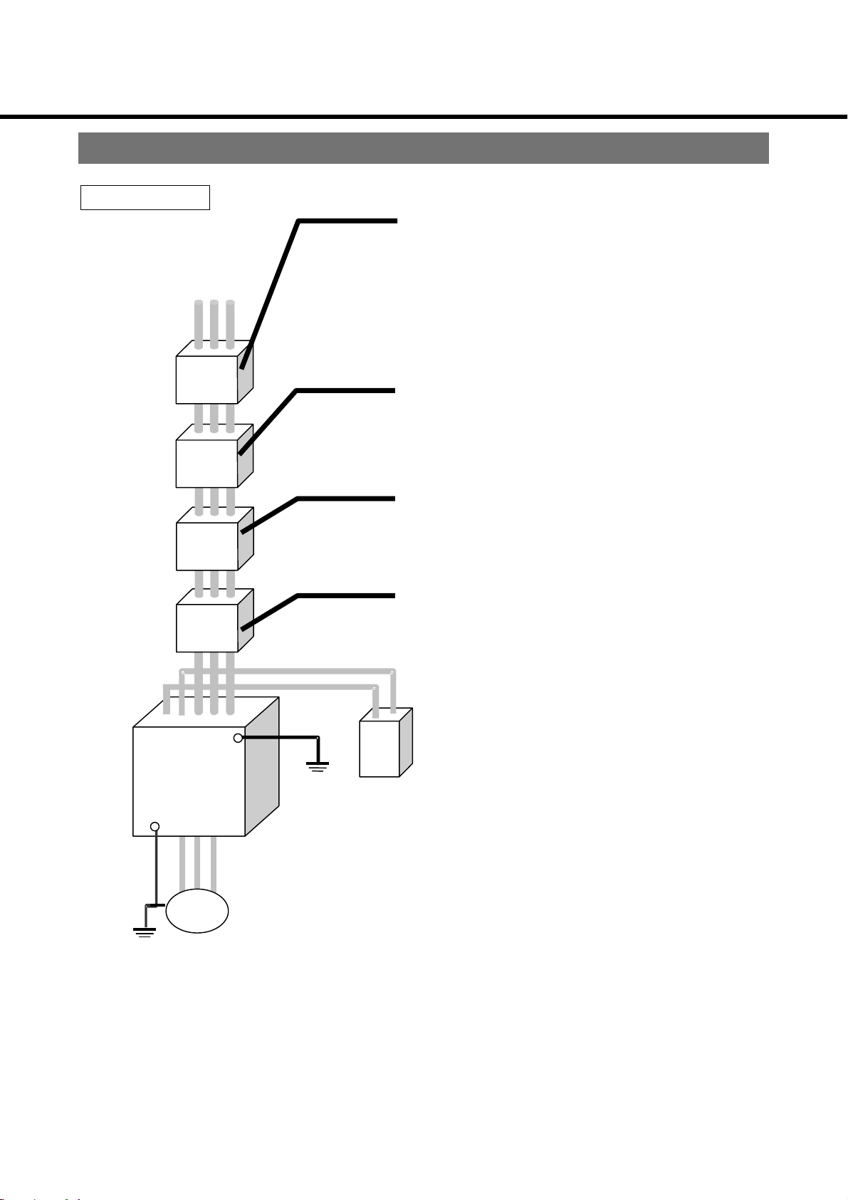
System Configuration and Wiring
A
Wiring general view
Main circuit
No-fuse breaker (NFB)
or Earth leakage breaker
Used to protect the power line.
Interrupts the circuit in the case of excessive
current.
Noise filter (NF)
Blocks noise from the power line.
lso reduces effect of noise from the servomotor .
Magnetic contactor (MC)
Turn main power to servomotor on/off.
Used with surge absorber mounted.
Inverter
Motor
Reactor (L)
Reduces harmonic current of the power source.
DC reactor
GND
‑11‑
Page 12
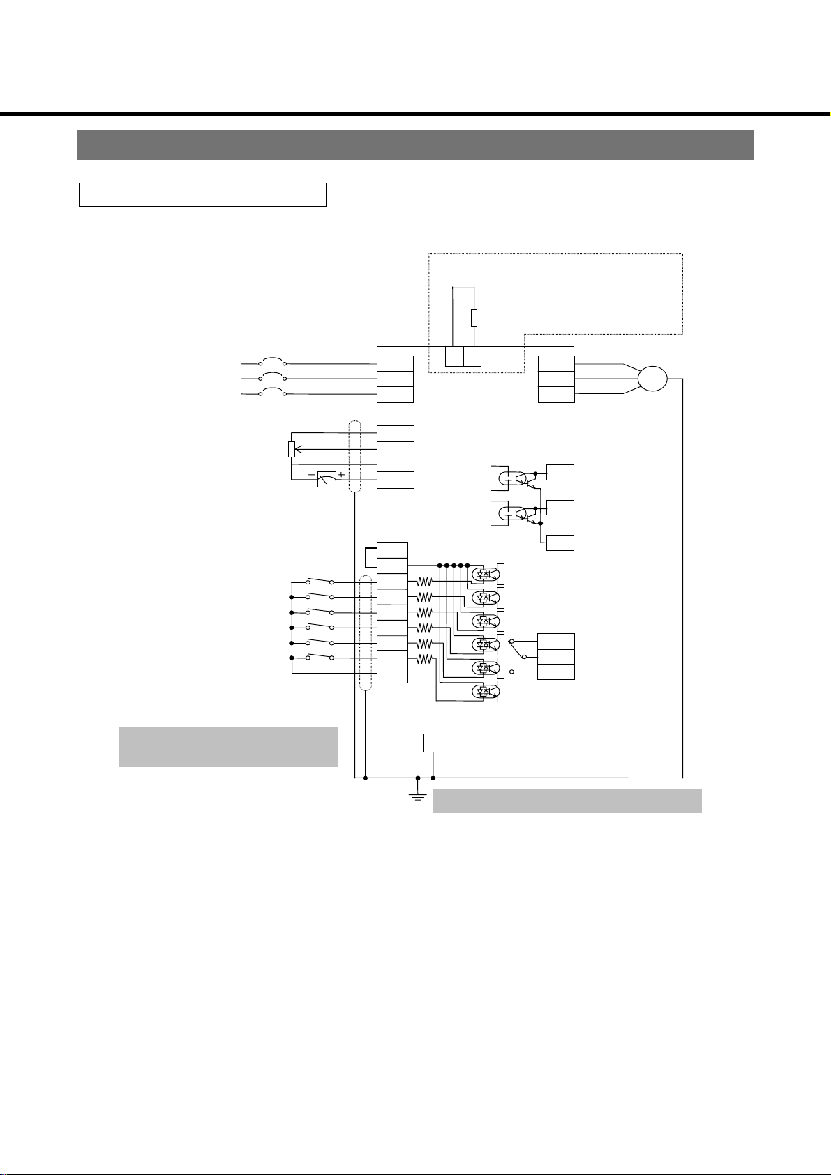
System Configuration and Wiring
I2I3I4
Wiring
Standard wiring diagram
External feedback resistor
(5.5 kW-11kW only)
Those lower than 3.7 kW and 15Kw
have no terminals for feedback resistor
Power source 3-phase
AC380〜460V
50/60Hz
External frequency setting volume
1/4W, 5kΩ, B characteristic
Frequency meter
1mA (full scale)
Forward/stop switch
Reverse/stop switch
Frequency setting selection (1)
Frequency setting selection (2)
Free-run
Trip reset
Ground for control
*
Be sure to provide proper treatment
for the shielded wire terminals.
NFB
R/L1
S/L2
T/L3
③
②
①
Note1)
5V
FIN1
G
FOUT
12V
PLC
I1
I5
16
G
PB
(Frame ground)
E
U/T1
V/T2
W/T3
(Collector)
O1
trip output
(Collector)
O2
Reach-signal
(Emitter)
COM1
V
CE
max.=50mA
I
C
NC
Trip signal
COM2
Contact capacity
NO
AC30V 2A
DC30V 2A
Motor
GND terminal
*
*
max.=DC24V
Be sure to ground
Asterisk (*) indicates factory-set function.
Note 1) PLC terminals and 12V ter minal s connect ed, it is called sy nchroniz ed inp ut circui t.
PLC terminals and G terminals connected, it is called power input circuit.
‑12‑
Page 13
System Configuration and Wiring
3
3
Terminal function
Not used
(1) Main circuit terminal ↓
E
750W〜3700W 5.5kW
R/L1S/L2 T/L3U/T1V/L2
/L
E E E
R/L1S/L2 T/L3
P
Not used
↓
E E
15
Terminal No.
R/L1, S/L2, T/L3
U/T1, V/T2, W/T3
R/L1 S/L2 T/L3
Terminal
name
Power
source input
terminal
Output
terminal
Connect to commercial power sourc e
(3-phase 380-460V 50/60 Hz)
Connect to 3-phase induction motor
P
N U/T1 V/T2 W/T3
kW
Function description
PB
〜11kW
U/T1V/T2
/T
E
P P terminal (+) terminals for the recitification part
N N terminal (-) terminals for the recitification part
PB PB terminal
GND
terminal
Terminal for grounding inverter base
Terminals for external feedback resistor.
Connect the resistor between P and PB.
‑13‑
Page 14
System Configuration and Wiring
t
(2) Control terminal
01 02 F1N1 F1N2 FOUT I2 I4 I6 12V
COM2 NC NO COM1 12V PLC G I1 I3 I5 G 5V
Terminal No. Terminal name Function description
Power source
5V
12V
FIN1
FIN2
G
FOUT
terminal for frequency setting
External power
terminal
Input terminal
for frequency
setting
Ground for
control
Frequency
meter terminal
+ 5VDC applied.
+ 12VDC applied.
The common terminal used for contact input of external power is used.
When power is on (PLC and G connected), a closed terminal in ON,
and an open one, OFF
Frequency can be set when 0 ~ +5VDC (or 0 - +10VDC) is input
between “FIN1” and “G”, or 4-20mA between "FI N2"-G. If both are input ,
the bigger will be pick up.
If using these terminals, change “
−
Common ground terminal for contact input. The common terminal used
for contact input of synchronized input is used. When power is on (PLC
and 12V connected), a closed t erminal in ON, and an open one, OFF.
Outputs voltage proportional to output frequency between “FOUT” and
“G.” Connect full-scale 1 mA DC ammeter. You can output pulses
synchronized with output fr equency by altering “
or
−
.
frequency command” to
FOUT switch”.
Input terminal
I1
I2
I3
I4
I5
I6
G
O1
O2
COM1
Forward/stop
command
terminal
Reverse /stop
command
terminal
Frequency
setting
selection
terminal
Ground for
control
Output signal
terminal
Forward by shorting between “I1” and “G”; stop by release
Reverse by shorting between “I2” and “G”; st op by release
You can change “I1” to run/stop command and “I2” t o forward/reverse
command by altering“
You can select the following functions in operation mode.
Operation mode I3 I4 I5
2-speed operation mode
4-speed operation mode
8-speed operation mode
16-speed operation mode
Contact input common ground terminal.
Open-collector output termina l. (Not maintained when power is OFF.)
You can select contents by “
Factory setting: “01” is trip signa l (transist or ON when tripped)
“O1” (collector) IC max. = 50mA
“C1” (emitter) VCE max. = 24VDC
I1.12” function selection.
Forward
jogging
Frequency setting
selection
Reverse
jogging
output signal (1) selection.”
Select from among
free-run, external forced
trip, No. 2 acceleration/
deceleration, trip rese
Output terminal
NC
NO
COM2
Output signal
terminal
Relay output termina l. 30VDC 1A (max.)
(Not maintained when power is O FF. )
You can select output contents by “
Not built-in to products without regenerative brake circuit.
relay output polarity selection.”
‑14‑
Page 15
System Configuration and Wiring
Precautions when wiring
Main circuit
(1) The inverter will be damaged if you invert the connections of the power input terminal
and motor output terminal (U/L1, V/L2 ... W/L3). Absolutely do not invert connections.
(2) Do not ground the main circuit terminal.
(3) Do not short motor output terminals (U/L1, V/L2 ... W/L3) together.
(4) The GND terminal (E) is the frame ground (FG) for the inverter.
(5) Be sure to use insulated crimp terminals for connecting to the main circuit terminals.
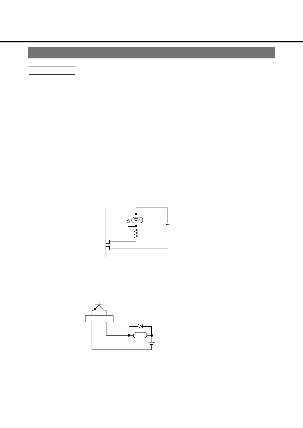
Control circuit
(1) Do not apply more than 24VDC, 50mA to the output terminals (O1, O2, −COM1), or
apply voltage to terminal in reverse.
(2) Input terminal configuration is shown in the following figure.
You can control by contact or by open collector output. Do not apply external voltage.
Internal circuits are as follows:
Photo coupler
Inverter internal power source
+12V
I1〜I6
GND
(3) Do not short the frequency setting power source terminal (5V) and ground for control
terminal (G).
(4) To directly drive the relay by the output terminals (O1, O2, −COM), mount a flywheel
diode (FD).
C1
O1/O2
FD(100V 1A)
Y
R
<Examples> Fuji Electric ERA15-01
ERB12-01
Pay attention to polarity of diode.
(5) Use shielded wires for the cable to be connected to the control circuit.
‑15‑
Page 16

Parameter Setting
How to set
Operation Panel
r/min
Hz
^
^
A
V
STOP
DATA
SET
RUN
MODE
2-digit LED
Frequency Hz is displayed when in the normal mo nit or mode.
You can display synchronized rotations for the parameter "
5-digit LED
display power."
5-digit LED
2-digit LED
MODE
button
DATA SET
button
Displays output freque ncy, set frequency or display power, cause of error, or
parameter.
Displays parameter No. Direction of rotation is displayed in the monitor mode.
Switch for changing monitor mo de. Pressing the switch change s t he mode in the
cycle of:
Output frequency Rectificated Motor current
Switch for selecting parameter No. mode and parameter value mode, setting
parameter value.
Mode description
●
Monitor
mode
Parameter
No. mode
Displays output freque ncy, rectificated voltage or motor current.
Mode when the power is turned on.
When in the parameter No. mode or parameter value mode,
pressing the MODE
Displays parameter No.(
When in the monitor mode, pressing the DATA SET
changes to the parameter No. mode.
switch changes to the monitor mode.
〜
)by flashing.
switch
△
▽
button
RUN button
STOP
button
Parameter
value mode
Enable you to select parameters, and set/change contents.
Commands the inverter to run.
Commands the inverter to stop.
Displays parameter content s (set t ing value) by flashing.
You can change the setting value with the △ ▽ switches.
After changing the setting, press the DATA SET
enter the setting in the memory.
‑16‑
switch to
Page 17

Parameter Setting
Power ON
Push DATA SET
Monitor mode
Push
Output frequency
MODE
Rectificated voltage
MODE
Motor current
Display LED used to show
Use △ ▽ to set or
change set speed of speed 0.
Parameter
MODE
Push
MODE
Use △ ▽ to select
parameter
number mode
parameter number in
parameter number display
Push
Push DATA SET
Parameter
value mode
Push DATA SET
MODE
LED used to show
parameter value in
parameter number display
Use △ ▽ to select
value
‑17‑
Page 18

Protective Function
Protective functions
The protective functions classified as shown below are built-in the inverters of this series.
① Functions that do not display a warning, but act to avoid a tripping of the system.
② Functions that display a warning and shut off inverter output.
③ Functions that trip the inverter. (Trip signal cannot be retained when the power is
turned off.)
Classification
①
②
5-digit LED display Description of prote ct ion Countermeasures, etc.
Electronic thermal
relay operation
Monitor display flashes when output
current reaches the electronic thermal
relay level and the timer operat es.
Electronic thermal relay trip.
Be careful of the size of the
load when using.
(Monitor)
(Flashes)
Acceleration/
deceleration stall
prevention
Prevents tripping when acceleration/
deceleration time becomes too long in
the following situ ations:
Increase acceleration/
deceleration time or
decrease inertia load.
(no display)
・
DC voltage of the rectificated part
exceeds approx. 775V.
・
Motor current exceeds inverter’s
current limit operation po int.
Insufficient voltage
warning
If DC voltage of the rectificated part
drops below approx. 360V, it is
Investigate the wiring and
power source informatio n.
regarded as “instantaneous power
Instantaneous
power failure
protection
failure,” and inverter output is shut o f f.
If it drops below approx. 300V, the
control circuit is reset. If voltage is
*1
restored by the time the control circuit
is reset, operation can be restarted
automatically.
*2
③
Reverse prevention
*3
Selecting the reverse prevention
function prevents reverse operation if
Check if the reverse
command has been given.
the inverter receives a reverse sign al.
Restart prevention
when power is
restored
*2
Prevents the inverter from restarting
automatically if already given the run
command when power is turned,
After commanding the
inverter to stop, command it
to run again.
restored following power failure or
reset.
*1
The inverter will operate correctly if power failure does not exceed approx. 15ms.
*2
Prevents the inverter from restarting automatically if “ restart prevention when power is restored” is selected for
.
*3
Effective only when “ reverse prevention” is selected for .
‑18‑
Page 19

Protective Function
Classification
5-digit LED display Description of protection Count ermeasures, etc.
Over-current trip
Regenerative overvoltage trip
Trips if inverter output current
exceeds the rated current approx.
by 200%.
Trips if DC voltage of the
converter rises above approx.
800V.
Possible causes in cl ude drop in
power source voltage, excessive
2
load, acceleratio n/
GD
deceleration time is set too short ,
load short, or grounding. Take the
proper measures to determine
the cause.
If it trips while the inverter is
running, deceleration time could
be too short. Try setting
deceleration time longer. If it trips
when the power is turned on, the
inductance of the power-boosting
AC reactor provided on the input
side of the inverter may be too
high. Select an AC reactor that
matches the inverter capacit y.
④
Over-voltage trip
retry when power is
turned on
Over-load trip
(Electronic thermal
relay)
CPU
error
If over-voltage trip occurs when
the power is turned on because
the inductance of the powerboosting AC reactor provided on
the input side of the invert er is t oo
high, etc.,
and output is shut off.
The trip is automatically reset
when DC voltage of the converter
drops below approx. 800V,
enabling normal operat ion.
If motor current continues to
exceed the electronic thermal
relay setting value, load is
regarded as being to high
causing the function to t r ip.
Trips if a control microcomputer
error is detected.
is displayed
*1
The capacity of the powerboosting AC reactor provided on
the input side of the inverter may
be too large. Select a reactor that
matches the inverter capacit y.
Try reducing load, modifying
operating pattern, or raising
capacity of inverter.
A malfunction caused by outside
noise could have occurred.
Check the area for noise and
remove the source of noise.
*1
Effective only when “ over-voltage trip retry when power is turned on” is selected for .
‑19‑
Page 20

Protective Function
Classification
④
5-digit LED display Description of protection Count ermeasures, etc.
Self-diagno sis t rip
External forced trip
Trips if parameter such as “
operation mode selection” is
changed.
Trips when “ I5 function
selection” is set by external
forced trip and I5 – G becomes
open.
Cancel by trip after shorting.
There is nothing wrong with the
equipment. The results of the
change become effective when
the trip is reset.
Investigate the cause of overlo ad.
Try reducing the load, changing
the operation pattern, or raising
the capacity of the inverter and
motor.
Method of resetting trip
In the event of a trip, remove the cause and cancel by one of the following methods.
[1] Turn off the inverter’s power. When the trip display disappears, turn the power
on.
[2] Short between both I1 – G and I2 – G for at least 0.1 seconds while the cause of
the current trip is being displayed.
*1
[3] Press both △ ▽ switches on the operation panel simultaneously for at
least 1 second while the cause of the current trip is being displayed.
[4] Input the trip reset command while the cause of the current trip is being
displayed.
*2
※ A CPU error cannot be reset by methods 2, 3 or 4. Reset by method 1
given above.
*1
Cannot be reset if “ I1.I2 function selection” is set to I1: Run/stop or I2: Forward/reverse.
*2
Effective only when “ I5 function selection” is selected for .
‑20‑
Page 21

Maintenance/Inspection
●You should perform maintenance/inspection on a regular basis in order to ensure safety
and keep the inverter in good running order.
Precautions when performing maintenance/inspections
(1) The power should be turned on/off only by the person performing the task.
(2) The internal circuits of the inverter remain charged with high voltage for a short while
after power is turned off. To perform inspection, first turn off the power and then wait for
the LED display on the front panel to go off (min. 5 minutes).
(3) Do not perform insulation resistance measurement on the inverter. Doing so will
damage the inverter.
Inspection items and environment
Ordinary/normal usage c ondi tions
Ambient conditions: Annual mean temperature 30°C, min. 20 hrs/day at max. load rate 80%
Perform daily and periodic inspections in accordance with the following items:
Classification Inspection cycle Inspection items
・
Ambient temperatur e, humidit y , dirt, dust, foreign o bjects, etc.
・
Is there abnormal vibration/noise?
・
Is main circuit volt age normal?
・
Daily
inspection
Periodic
inspections
Daily
1 year
Is there strange odor?
・
Is there lint in the air holes?
・
Cleanliness of control unit
・
Is wiring damaged?
・
Are equipment connections loose or off center?
・
Are foreign objects lodged in at the load side?
・
Are fastened sections loose?
・
Is there evidence of overhe ating?
・
Are terminal blocks da ma ged?
<Caution>
Inspection cycle for periodic inspections may vary if usage conditions differ from those
given above.
Approximate period for part replacement
Period for part replacement varies according to how the inverter is used. Parts must be
replaced or repaired when something is wrong with them. Under the ordinary/normal
usage conditions.
Product
name
Inverter
Smoothing capacitor Approx. 5 years
Cooling fan
Aluminum electrolytic
capacitor of PC board
Part name Standard replacement
period (hrs)
2〜3 years
(1〜30,000 hrs)
Approx. 5 years
Remarks
Standard replacement period gives
a number of years for reference
only. If a part becomes faulty it must
be replaced even if the standard
replacement period has not yet
been reached.
‑21‑
Page 22

Troubleshooting
Inspection to determine cause of problem
When a prob lem occurs , perform th e inspe ctions and t ake the m easures pre scribed in the
following table. If you cannot determine the cause of the problem, if you suspect that the
inverter is not working properly, if a part is damaged, or there are any other problems you
cannot solve, contact your Panasonic dealer.
Problem Description of inspection Corrective measures, etc.
Motor doesn’t work.
Motor turns in
reverse.
Is there anything wrong with the
wiring?
Is power being supplied to the power
input terminals?
Is the LED on the operation panel lit? Recheck the above.
Is the voltage of the power in put
terminals normal?
Is an error being displayed? See “protective function”.
Has free-run been commanded? Cancel free-run.
Are both the forward AND reverse
switches on?
Is there anything wrong with the
frequency setting?
Is the motor locked? (Is the load too
heavy?)
Is phase interruption operation being
carried out?
Is there a mistake in the phase order
of the output terminals (U/T1, V/T2,
W/T3)?
Wire correctly.
Turn on the power.
Turn off the power once, and then turn
back on.
Check power source voltag e.
Turn either the forward OR reverse
switch on, and the other off.
Check the frequency sett ing.
Cancel the motor lock. (Reduce the
load.)
Recheck the wiring between the
inverter and motor.
Match the phase order of the output
terminals (U/T1, V/T2, W /T3) with the
motor.
The motor runs but
speed doesn’t change.
Motor speed is not
correct.
Motor speed is
unsteady.
Is the load too heavy? Reduce the load.
Are the number of poles and volt age
of the motor correct?
Is voltage of the power input
terminals (R/L1, S/L2, T/L3) c orrect ?
Is the frequency setting range
normal?
Has motor terminal voltage dropped
excessively?
Is the load too heavy? Reduce the load.
Is load variation too large? Reduce load variation. Raise the
Check the specificat ion manual and
name plate.
Check power source voltag e.
“
lower limit frequency”
upper limit frequency”
“
“
base frequency”
max. output voltage adjustment”
“
V/F reduction characteristics”
“
capacity of the inverter and motor.
‑22‑
Page 23

Detailed Explanation of Parameters
Parameter functions
No. Parameter name
Setting frequency
(0 speed)
1st speed frequency
nd
speed frequency
2
rd
speed frequency
3
th
speed frequency
4
th
speed frequency
5
th
speed frequency
6
th
speed frequency
7
th
speed frequency
8
th
speed frequency
9
th
speed frequency
10
th
speed frequency
11
th
speed frequency
12
th
speed frequency
13
th
speed frequency
14
th
15
speed frequency
Run command
selection
Explanation
Sets the frequency with which you want to run the machine.
Valid when “
This sets the frequency when running in multi-speed mode.
Valid when “
Allows you to set 4th speed frequency to 15th speed frequency when you select
16 speed running mode for “
Operation Mode
frequency command se lect” is
Running mode select” is higher than 4th speed operation.
Running Mode Select.”
Input Terminal
I 3 I 4 I 5 I 6
8 Speed Operation Mode
16 Speed Operation Mode Frequency Setting Selections
This selects the run command from the following.
●
(PANEL) :
Frequency Setting
Selections
RUN
switch on the operation panel.
No. 2 Acceleration/
Deceleration
.
Frequency command
selection
■
V alues set at ex-factory.
●
■
When
※
command.
This selects whether to set the 0 speed frequency using “
(0 speed), ” the input terminal for Frequency Setting Selections “F1” or the switch on
the main unit.
■
●
●
●
(TERMINAL) : Input terminals “I1” and “I2”
(BOTH): Both operation panel and input terminals are
valid.
is selected, you cannot use the input terminal as the run
setting frequency
" setting frequency (0 speed)"
Analog Command “FIN1”
(Voltage Command) DC 0 to 5 V
Analog Command “FIN1”
(Voltage Command) DC 0 to 10 V
Volume on Main Unit
‑23‑
Page 24

Detailed Explanation of Parameters
No. Parameter name
Operation mode
selection
Torque control
Explanation
These are the parameters that select the operation mode.
●
■
●
●
●
This adjusts the voltage output of the inverter at a low frequency region.
Be aware that as the settings are
※
increased, excessive current will
flow which will cause a trip.
●
●
2nd Speed mode
4th Speed mode
8th Speed mode
16th Speed mode
〜
: Auto-boost Controls for the optimum auto-torque for the
inverter and motor with the same capacity.
: Auto-boost Controls for the optimum a little weaker auto-
torque for the inverter and motor with the same capacity.
Manual torque boost
:
Maximum output voltage
Large
Output voltage
0
Small
Base frequency
Output frequency
●
<Precautions regarding the selection of Auto-boost and slip frequency compensation>
Select parameters when the motor is stopped.
・
Do not use when running in serial.
・
There are cases in which the system will be unstable dep end ing on th e c ond itions of
・
the load. If that should occur, set the manual torque boost.
When running at a high power supply voltage, adjust to lower the output voltage of
・
the inverter using “
adjustment.”
Jogging frequency This sets the frequency for operating in the jogging mode.
Acceleration time
This determines the rate of change of the output frequency during acceleration.
Sets the time that changes in 50 Hz.
・
When set to 0 seconds, ac celerati on is at its op timum sp eed and deceler ation w ill b e
・
0.01 second.
When less than 3 seconds set to 0.01 sec intervals; When 3 to 9 seconds set to 0.1
・
sec intervals; When 10 seconds or more set t o 1 sec interv als.
: Controls slip frequency compensation.
Controls compensation of the slip frequency for the motor
selected by “
motor selection.”
Base frequency” or “ Maximum output voltage
No. 2 Acceleration
time
■ Values set at ex-factory.
This sets the acceleration time of the No. 2 Acceleration.
This is valid when you select “
No. 2 accel/decel.time.
I5 Function Selection” in the
‑24‑
Page 25

Detailed Explanation of Parameters
No. Parameter name
No. 3 Acceleration
time
No. 4 Acceleration
time
DC brake volume
DC brake time
DC braking time This selects the type of DC brake.
Starting brake time This runs the inverter after applying the DC brake to the motor for the amount of time
This sets the acceleration time of the No. 3 and No.4 Acceleration.
This is valid when you select “
Selection” in the
This adjusts the DC brake time and the DC brake volume when shifting from inverter
drive to a stopped state.
- The machine will enter a free-run when either or both the time and volume are set to
0 (zero).
※ The DC brake time when you select a sudden brake (all regions) will be twice the
time of the positioning brake.
■
set when you are starting up. This does not function when you set to 0 (zero).
・ The strength (torque) of the DC brake (torque) is the “
but be careful because it does not operate when set to 0.
: Position
Explanation
I5 Function Selection” “
No. 2 accel/decel.time .
●
: Sudden stop (all regions)
DC brake volume”
I6Function
Brake start frequency This adjusts the frequency for starting to apply the positioning DC brake.
Carrier frequency
variable
■ Values set at ex-factory.
・ The DC brake will be applied when the output frequency is lower than “Brake start
frequency” when you cause a soft-stop using the stop command and stop from
normal operation.
・ The DC brake will be applied when lower than 1 Hz regardless of the settings of
“Brake start frequency” when it stops because the frequency settings are low while
in normal operation.
This is the parameter that selects the carrier frequency. This selects the following 8.
Change the carrier frequency when the motor is stopped.Do not change while it is
operating.
Setting value Carrier frequency Setting value Carrier frequency
0 1.2kHz 4 8.0kHz
12.6kHz■5 10.1kHz
2 3.9kHz 6 12.0kHz
3 6.0kHz 7 14.9kHz
‑25‑
Page 26

Detailed Explanation of Parameters
A
e
(
)
No. Parameter name
Explanation
Deceleration time This determines the rate of change of the output frequency when decelerating.
・ Sets the time that changes in 50 Hz.
・ When set to 0 seconds, acceleration is at its optimum speed and deceleration will
be 0.01 second.
・ When less than 3 seco nds set to 0.01 sec intervals; When 3 to 9 seconds set to 0.1
sec intervals; When 10 or more seconds set t o 1 sec interv als.
No. 2 Deceleration
time
This sets the deceleration time of the No. 2 Deceleration.
This is valid when you selec t “
I5 Function Selectio n” in the
accel/decel.time.
No. 3 Deceleration
time
This sets the deceleration time of the No. 2 Deceleration.
This is valid when you select “
Selection” in the
No. 2 accel/decel.time.
I5 Function Selection” “
No. 4Deceleration
time
Base frequency This sets the base frequency (maximum
Maximum output voltage
frequency of the torque region) to any
frequency within the range of 30 to 400 Hz
that matches the motor rating.
Output voltage
0
Output frequency
I6Function
Adjustment range
(30 ~ 400Hz)
Base frequency
No. 2
Max. Output voltage
adjustment
V/F reduction
characteristics
■ Values set at ex-factory.
This adjusts the maximum output voltage
(base frequency voltage). The range of
adjustment is 0 to 100%.
Maximum output voltage
100 :
Power supply
voltage
Output voltage
0
Output frequency
djustment rang
0 ~ 100%
Base frequency
This adjusts the V/F characteristics to match
the load characteristics.
●
Rated torque load
●
Reduction torque load
1.0
Output voltage
0
Large
Base frequency
Output frequency
You can make fine adjustments between 1.0
and 2.0.
Note: This is valid only when you have selected “torque control” in the manual boost.
‑26‑
Page 27

Detailed Explanation of Parameters
0
No. Parameter name
No. 2 V/F selection
No. 2 V/F base
frequency
No. 2 V/F boost
Explanation
This sets the special V/F pattern using “No. 2 V/F selection.”
This selects the No. 2 V/F upper pattern
set using the normal V/F and “No. 2 V/F base frequency” and “No. 2 V/F boost.”
■
●
●
Normal pattern
Upper pattern
Lower pattern
Note: This is valid only when you have selected “torque control” in the manual boost
or the lower pattern
No. 2 V/F
Output voltage
Normal V/F
0
Output frequency
Upper selection
Output voltage
0
Output frequency
Lower selection
Output voltage
0
Output frequency
.
Jump frequency width
Jump frequency 1
Jump frequency 2
Jump frequency 3
Jump frequency 4
This creates areas that cannot set the
frequency in a range set by “
Jump
frequency width” above and below as the
center of the frequency set by “
frequency 1” to “
Jump frequency 4”
Jump
Set frequency
Frequency Frequency Frequency
1 2 3
Frequency command (Between FIN and G)
in order to avoid mechanical resonance.
・
Acceleration time outputs the frequency even in the jump region.
・ If jump frequency ranges are overlapped, it jumps all overlapping ranges.
I1/I2 function selection This switches the input terminals “I1” and “I2” in the following manner.
Input terminal
■
(
:
Fwd-Stop/Rev-Stop
Between “I1” and “G” Between “I2” and “G”
Short Open Short Open
Forward
Operation
Stop
Operation Stop
Reverse
Operation
Reverse Forward
:
Run-Stop/Fwd-Rev)
Jump frequency width
Stop
■ Values set at ex-factory.
‑27‑
Page 28

Detailed Explanation of Parameters
No. Parameter name
I5 function selection
I6 function selection
Multi-speed input
selection
Explanation
This selects the input terminals “I5” functions in the following manner.
●
:
“Terminal” – “G” Short
●
:
“Terminal” – “G”
●
:
selection
“Terminal” – “G” short
■
※
This selects the type of frequency setting for multi-speed operation.
●
“Terminal” – “G” short
Set the status of the short “Terminal” – “G” before selecting “
When open, a trip occurs.
(FREE)
(THeRmal)
→
(UpーDown)
(ReSeT)
(1bit):1 bit input
→
Free-run Stop
External forced trip command
No. 2 acceleration and deceleration time
→
→
Trip reset command
.”
Not used
■ Values set at ex-factory.
This selects 1 type of multi-speed frequency for 1 terminal of the “Frequency setting
selection terminals.” This runs the inverter in 3 speeds in 4 speed operation mode
and 4 speeds in 8 speed operation mode.
Ex.) With 8 speed mode operation
Input terminals
I3 I4 I5
Open Open Open
Short
Open Short
Open Open Short
■
This selects the frequency by setting “Frequency setting selection terminals” in
binary.
××
×
(Binary):Binary input
Frequency setting
No. 0 speed
frequency
No. 1 speed
frequency
No. 2 speed
frequency
No. 3 speed
frequency
・ Open and short
are related to “G”
and terminals.
・× means there
is no relationship
between short
and open.
‑28‑
Page 29

Detailed Explanation of Parameters
No. Parameter name
Output signal 1 selection
Output signal 2 selection
Explanation
This selects the output signal between output terminals “O1” to “O2” in the following
manner.
■
:
●
:
Trip output signal (When trip: ON*)
Arrival signal (When arrival: ON*)
●
:
●
:
Run/Stop signal (When run: ON*)
Free-run singnal (While Free-run: ON*)
●
:
Forward operation signal (While forward operation: ON*)
●
:
●
:
→
Reverse operation signal (While reverse operation: ON*)
Output frequency detection signal
Refer to:
(TRIP)
(STaBLe)
(RUN)
(FREE)
(Fwd)
(Rev)
(CheckーF)
Compare frequency A” and “
Compare frequency B”
●
:
→
●
:
●
:
Motor current detection signal
Refer to “
DC brake signal (While DC brake: ON*)
Trip cause detection signal
(CheckーC)
Motor current detection level”*
(DC-Brake)
(CAUS)
The following signals are output when a trip occurs.*
Trip contents
Normal over-current
Acceleration over-current
Deceleration over-current
Over-voltage
External forced trip
Electronic thermal
CPU error
ON time
Continuous
3 seconds
1 second
1 second
0.25 second 0.25 second
0.9 second
0.1 second
OFF time
1 second
3 seconds
1 second
0.1 second
0.4 second
■ Values set at ex-factory.
* “
selection.”
Self-diagnosis
output signal 1 selection” can invert “
‑29‑
0.5 second
output signal 1 polarity
0.5 second
Page 30

Detailed Explanation of Parameters
No. Parameter name Explanation
Relay output selection
This selects the output signal w hen the rel ay output b etween “NC,” “CO M 2” and “NO” is
used. Trip output signal
●
●
●
●
●
●
(TRIP):Trip output signal
(When trip: Between “NC” and “COM 2”: O pen, Betw een “NO”
and “COM2”:Closed)
(STaBLe):Arrival signal
(When arrival: Between “NC” and “COM2”: Open, Between
“NO” and “COM2”: Closed)
(RUN):Run/stop signal
(When run: Between “NC” and “COM2”: Open Between “NO”
and “COM2”: Closed)
(FREE):Free-run signal
(When free-run: Between “NC” and “COM2”: Open, Between
“NO” and “COM2”: Closed)
(Fwd):Forward operation signal
(When forward operation: Between “NC” and “COM2”: Open,
Between “NO” and “COM2”: Closed)
(Rev):Reverse operation signal
(When reverse operation: Between “NC” and “COM2”: Open,
Between “NO” and “COM2”: Closed)
Motor current
detection level
Output signal 1
polarity selection
Current limit operating
point
■ Values set at ex-factory.
●
●
Set the current level you want to detect using a percentage for the rated current of the
inverter when you selected “
selection” in
exceeds the detection level you set and it will turn “OFF” when it is below.
This function inverts the polarity of the output signal between output terminals “O1” and
“COM1.”
■
●
This limits the operating point for the motor current that was set.
Numbers are percentages for the inverter rated current.
(NORmal): When operation: transistor “ON”
(REVerse): When operation: transistor “OFF
(Check-F):Output frequency detection signal
→"
Refer to “
(Check ー C):Motor current detection signal
→Refer to “
. The output terminal will operate when the motor current
Compare frequency A,” and
Compare frequency B."
Motor current detection level.”
Output signal 1 selection” and “
Relay output
‑30‑
Page 31

Detailed Explanation of Parameters
No. Parameter name Explanation
Stall deceleration
magnification
Acceleration mode
switch
Deceleration mode
switch
This adjusts the decelerat ion tim e when the stall prevention function of the decelerati on
is operating.
・Set in percentages for the deceleration time of the normal setting.
This selects the straight line acceleration/deceleration or curved line (S) acceleration/
deceleration independently.
■
Output frequency
0
This is a general
acceleration mode to
accelerate and decelerate
on a straight line up to the
set frequency.
Straight line ● S Shape 1 ● S Shape 2
Time
utput frequency
Base frequency
0
Time
With large output of the
motor torque, the incline is
steep and when the output
torque is small, the incline
is gentle.
Output frequency
f2
f1
0
Time
This shows an S
characteristic between
running frequencies f1 t o f2.
This is a smooth acceleration and deceleration
characteristic.
* This changes using the acceleration and deceleration time set when under the base
frequency if you select
S shape 1, but when over the base frequency,
the incline is gentler than the set time.
Monitor mode switch This selects the content that displays in the 4 digit LED.
Display magnification This sets the magnification of the value that displays in the 4 digit LED. This displays
■ Values set at ex-factory.
The value to which the “
display magnification” was applied is displayed with the
frequency display.
■
●
Output frequency ●
Set frequency ● Converter unit DC voltage
Output current
the motor synchronized rotation or the line speed.
* The parameters related to frequency (below) display the value to which the display
magnification was applied when you change the display magnification.
〜〜〜〜 0 to 8th speed frequency” " 〜〜〜〜 Compare frequency"
"
Jogging frequency" "Matching detection width"
"
Brake start frequency" " Instantaneous drop frequency"
"
" 〜〜〜〜 Jump frequenc y" "Lower limit frequency"
Frequency meter full scale indication" " Upper limit frequency"
"
‑31‑
Page 32

Detailed Explanation of Parameters
No. Parameter name Explanation
Frequency meter
adjustment
Frequency meter full
scale indication
This calibrates the frequency meter. Adjust using the △ ▽ switches so that
the needle on the frequency meter points at the full scale.
This indicates the frequency when using the frequency meter full scale. This is set to
60 Hz full scale at ex-factory so adjust to be used higher than 60 Hz.
“FOUT” switch This selects the frequency signal to output to the frequency output terminal “FOUT.”
■
●
Frequency analog output
Frequency digital output
● Current analog outp ut
Compare frequency A
Compare frequency B
This sets the frequency to detect when you selected “ output signal 1 selection”
and “
relay output selection” in the output frequency detection signal
.
- The output signal is ON when the outp ut fre que ncy exceeds*1 “compare frequency A”
and is OFF when it is less
Output frequency
0
ON
Between “01” and “COM”
*1
than “compare frequency B.”
Output frequency
A
B
0
ON
ON ON
Between “01” and “COM”
A
B
Match detection width This adjusts the timing to output the arrival signal during acceleration and deceleration
■ Values set at ex-factory.
When A ≧ B
when you selected “
the
arrival signal.
output signal 1 selection” and “ relay output selection” in
When A < B
- The arrival signal is output when the difference of the output frequency and the set
frequency is smaller than “match detection width.”
- The arrival signal is not output when 0 is set.
- The arrival signal is not output when forward/reverse are switched when stopped
or during DC brake.
- The arrival signal is output until immediately before stopping when “ brake
start frequency” < “match detection width.”
‑32‑
Page 33

Detailed Explanation of Parameters
No. Parameter name Explanation
Instantaneous drop
frequency
Instantaneous freerun time
Restart prevention
when power is
restored
Retry selection
Retry start time
This adjusts the output frequency after instantaneous stop or after the power is
restored.
- This starts the output from the value that subtracted “Instantaneous drop
frequency” from the output frequency of the instantaneous detection when power
was restored.
- It starts running from 0.5 Hz in the same way as when turning on the power under
normal conditions even though power is restored and the control circuit was reset
when the power cut was long.
This adjusts the free-run time after instantaneous stop or restoring power.
This prevents restarting after an instantaneous stop or after power was restored by
setting
You can try to continue running by automatically canceling the trip after “Retry start
time” even when a trip occurs. This will retry (re-execute) the set number of times but
if a trip does not occur in over approximately 120 minutes, the retry count will be
initialized.
■
.
(NO): Does not retry
● 〜 :Retries the set number of times
・Outputs a trip signal and stops when the set number of retries is reached but does
not output the trip signal (when trip is “ output signal 1 selection” and “
relay output selection”) during a retry.
* The retry function is invalid when Restart prevention when power is restored is set
to
Frequency setting
bias
Lower limit frequency This sets the lower limit of the inverter output frequency.
Upper limit frequency This sets the upper limit of the inverter output frequency.
Constant for input
filter
This sets the “0 V input frequency” of
the frequency setting input terminal
“FIN1.”
This sets the constant for input filter of the voltage or the current’s frequency setting
signal from an external source.
* Increase the constant of the filter if you cannot attain stable operation because of
the effects of noise. As you increase the setting value, response will worsen.
.
Set frequency
0V
0 V input frequency Frequency setting voltage
5 V input fr e que nc y
5V
(Between “FIN1” and “G”)
■ Values set at ex-factory.
‑33‑
Page 34

Detailed Explanation of Parameters
No. Parameter name Explanation
Over-voltage trip retry
when power is turned
on
Reverse prevention
Electronic thermal
relay
This displays the
on the power when you set to
Also, the trip is automatically canceled at the point the DC voltage falls below
approximately 400 V on the converter.
※ The display will change from to and it will consider the
normal over-voltage trip when you continue the over-voltage beyond a prescribed
amount of time after turning on the power supply.
This prevents the trouble caused by reversing when you set to
This adjusts the amount that the electronic
thermal relay functions.
・ Set the percentage for the inverter’s rated
current.
・ The operation panel display unit will flash
when the motor current exceeds the set
value.
※ It is necessary to check the ambient
temperature when the setting is higher
than the ex-factory setting.
and trips when an over-voltage trip occurs when turning
.
.
1 min.
50 100 150
Operating time
0
100% 150%
Parameter value
200%
Motor current
Trip cause clear This clears the cause of the trip.
<How to clear>
Trip cause 1
Trip cause 2
Trip cause 3
Trip cause 4
Trip cause 5
Parameter
initialization
① Use the △
is.
② After the display extinguishes, it will be cleared when the power is turned back on.
③ Switch the power supply again if the inverter does not operate in this state and use
after turning on the power again.
This remembers the latest 5 trips.
Refer to “Monitor” for details regarding the content of the display.
This initializes and returns all parameters to our standard ex-factory settings.
<How to initialize>
① Use the △
is.
② After the display extinguishes, it will be init ializ ed w hen the power i s turned bac k on.
switch to switch the power supply with the setting as it
will be displayed in the 4 digit LED.
switch to switch the power supply with the setting as it
will be displayed in the 4 digit LED.
③ Switch the power supply again if the inverter does not operate in this state and use
after turning on the power again.
‑34‑
Page 35

Detailed Explanation of Parameters
No. Parameter name Explanation
Motor selection
Start-up starting
frequency
Automatic voltage
regulation reference
voltage
Automatic voltage
regulation selection
Parameter lock This locks the parameters that you set.
Set the motor volume and polarity to use when you selected
compensation control) using “
* Select the motor when it is stopped.
This sets the inverter output starting frequency.
※ This increases the starting torque but it is close to a direct startup and is not
appropriate for a shock-less start. Also, there are cases of a trip occurring
depending on the load.
This selects the motor’s rated voltage when using automatic voltage regulation.
This corrects the output voltage and suppresses the variations in the output voltage for
the variations of the input power supply voltage.
However, you cannot output the value higher than the maximum output voltage or the
input power voltage.
Does not lock parameters
torque control.”
(slip frequency
Locks all parameters.
Locks parameters for which setting is unnecessary.
・
Setting to
switches become invalid. None of the parameters can then be set.
(
RUN and STOP switches are valid
・ Setting to
parameter extraction.”
Parameter copy This copies parameters.
Reads parameters to panel.
Writes parameters to main unit.
Parameters initialization on operation panel
Motor rated current This sets the motor rated current when using the slip frequency compensation control.
*
1
Motor current without
load
This sets the motor current without load when using the slip frequency compensation
control.
Does not copy parameters.
*
1
locks all parameters and the MODE △
allows setting of only the parameters selected by the “
▽
)
‑35‑
Page 36

Detailed Explanation of Parameters
No. Parameter name Explanation
Motor 1 primary
resistance
Slip correction gain Adjusts the slip correction gain when using slip frequency compensation control.
Sets the motor 1 primary resistance w hen usi ng slip fre quen cy compe nsatio n control.
*1
Slip correction
response time
Parameter extraction This extracts the parameter. Refer to “How to Extract Parameters” for details.
*1
Because slip frequency compensation control requires a motor constant, set to our standard motor constant that was
set at ex-factory. Set the motor constant to use when driving another motor.
Sets the slip correction res pons e t ime w hen us ing sl ip frequency compensation control.
‑36‑
Page 37

Specifications
Part Number M1X 84BSA M1X154BSA M1S224BSA M1X374BSA
Applicable motor (kW)
Output capacity (kVA)
Rated output current (A)
Rated output
Rated output voltage
Voltage 3-phase AC 380 to 460 V
Frequency 50/60Hz
Allowable voltage flu ctua tion
Power source
Allowable frequency fluctuation
Control method Low noise sine wave PWM style
Output frequency range 0.5 to 400 Hz (Start and stop from 0.5 Hz)
Frequency accuracy ± 0.5%(25°C ± 10°C
Frequency s etti ng r es ol uti on
Frequency setting signal
Voltage/Frequency
characteristics
Rated overload current 150%/minute
Regenerative brake
torque (Short time)
Control method
Acceleration/deceleration
Jogging frequency range 0 to 30Hz
Protective functions
Ambient conditions
Protective structure Built-in the panel (IP40) (With ventilation cover)
DC brake Brake start frequency/break operating time/brea k volume adjustable.
time
Operation mode
Others
Ambient temperature
Ambient humidity Relative humidity: 90% max. (No dew condensation is allowed)
Atmosphere Indoor (place free from corrosive gas and dirt or dust)
Altitude 1000m max.
Vibration 5.9m/s2 (0.6G) max. (10 to 60Hz)
Cooling method Self-cooling method
Weight (kg) 2.9
*1
*2
*3
・
・
0.75 1.5 2.2 3.7
2.0 3.0 4.4 7.2
2.5 3.7 5.5 9.0
3-phase AC 380 to 460 V
-15%, +10%
± 5%
)
Digital: 0.01 Hz
Analog: Setting frequency range/1000 Hz (minimum 0.05 Hz)
DC0 to +5V, 0 to +10V , 4 to 20mA
Base frequency: 30 to 400 Hz (1 Hz step), with reduced torque
pattern
150% min.
(Short time)
(0 to 3s: 0.01s step, 3 to 10s: 0.1s step, 10s or more: 1s step)
Time that changes in 50 Hz. Adjustable to a maximum of 4
kinds of acceleration/deceleration speeds.
2-speed operation mode, 4-speed operation mode,
8-speed operation mode, 16-Speed operation mode
Automatic boost, slip frequency compensation control selectable
AVR function/retry function selectable, parameter lock available
Insufficient vol t ag e pr ot ecti on, ov er-c urrent protecti on, over vol ta ge pr ot ec ti on,
instantaneo us po wer fail ur e pr otection, stall prev ent i on, over -l oa d li mit ati on (c urr e nt
limiter), overl oad tr i p (el ectri c thermal relay), rest ar t pr eve nt i on wh e n po wer is
restored, self- di ag nos i s tr i p (the l ast 5 c aus es of tri ps ar e st ored)
-10°C to +50°C (No dew condensation is allowed.)
When the ambient temperature exceeds +40°C, mount a ventilation
cover and rubber bush.
100% min.
(Short time)
0 to 3600 s(seconds)
(Short time)
70% min.
*1
Applicable motor: For Panasonic 3-phase in duction motor (4 poles)
When using another motor, select the motor within inverter ratings.
*2
Output capacity: If the rated output voltage is 460V.
*3
Output voltage does not become higher than the pow er source voltage.
‑37‑
Page 38

Specifications
Part Number M1X554BSA M1X754BSA M1XA14BSA M1XA54ASA
Applicable motor (kW)
Output capacity (kVA)
Rated output current (A)
Rated output
Rated output voltage
Voltage 3-phase AC 380 to 460 V
Frequency 50/60Hz
Allowable voltage flu ctua tion
Power source
Allowable frequency fluctuation
Control method Low noise sine wave PWM style
Output frequency range 0.5 to 400 Hz (Start and stop from 0.2 Hz)
Frequency accuracy ± 0.5%(25°C ± 10°C
Frequency s etti ng r es ol uti on
Frequency setting signal
Voltage/Frequency
characteristics
Rated overload current 150%/minute
Regenerative brake
torque (Short time)
Control method
Acceleration/deceleration
Jogging frequency range 0 to 30Hz
Protective functions
Ambient conditions
Protective structure Closed model (IP20)
DC brake Brake start frequency/break operating time/brea k volume adjustable.
time
Operation mode
Others
Ambient temperature
Ambient humidity Relative humidity: 90% max. (No dew condensation is allowed)
Atmosphere Indoor (place free from corrosive gas and dirt or dust)
Altitude 1000m max.
Vibration 5.9m/s2 (0.6G) max. (10 to 60Hz)
Cooling method Self-cooling method
Weight (kg) 7.8 8.5
*1
*2
*3
・
・
When the ambient temperature exceeds +40°C, mount a ventilation
5.5 7.5 11 15
10.4 12.8 19.2 25.5
13.0 16.0 24.0 32.0
3-phase AC 380 to 460 V
-15%, +10%
± 5%
)
Digital: 0.01 Hz
Analog: Setting frequency range/1000 Hz (minimum 0.05 Hz)
DC0 to +5V, 0 to +10V, 4 to 20 mA
Base frequency: 30 t o 400 Hz (1 Hz step), with reduced torque
pattern
70% min.
(Short time)
(0 to 3s: 0.01s step, 3 to 10s : 0.1s st e p, 10s or m or e: 1s st ep)
*Time that chan ges in 50 H z. A d j ust a bl e to a ma xi mu m of 4 kin ds of
2-speed operation mode, 4-speed operation mode,
8-speed operation mode, 16-Speed operation mode
Automatic bo ost , AV R fu nct i on/r et r y func ti on s electable
Slip frequency compensation control selectable, parameter lock available
Insufficient vol t ag e pr ot ecti on, ov er-c urrent protecti on, over v olta g e pr ot ect i on,
instantaneo us po wer fail ur e pr ot ection, stall prevent i on, over -l oa d li mit ati on (c urr e nt
limiter), overl oad tr i p (el ectri c thermal relay), rest ar t pr eve nt i on wh e n po wer is
restored, self- di ag nos i s tr i p (the l ast 5 c aus es of tri ps ar e st ored)
-10°C to +50°C (No dew condensation is allowed.)
50% min.
(Short time)
0 to 3600 s(secon ds )
acceleration/deceleration speeds.
cover and rubber bush.
30% min.
(Short time)
20% min.
(Short time)
*1
Applicable motor:For Panasonic 3-phase ind uct ion motor (4 poles)
When using another motor, select the motor within inverter ratings.
*2
Output capacity If the rated out put voltage is 460V.
*3
Output voltage does not bec ome higher than the power source v olt age.
‑38‑
Page 39

Outer Dimensions
●●●● MIX 0.75 〜〜〜〜 3.7kW
(Mounting dimension)
(Mounting dimension)
●●●● MIX 5.5 〜〜〜〜 11 kW
(Mounting dimension)
(Mounting dimension)
‑39‑
Page 40

Outer Dimensions
●●●● MIX 15 kW
(Mounting dimension)
(Mounting dimension)
‑40‑
Page 41

Parameter Setting
Parameter overview
Inverters of this series hav e vari ous parameters th at adjust /set charact eristics and functions,
etc. The objectives and functions of various parameters are described herein. Get a good
understanding of the parameters and use to adjust inverter to the best condition for the
customer’s operating conditions.
Parameter configuration and list of parameters
Parameter settingNo. Parameter name
*1
Setting frequency
(0 speed)
1st speed frequency
2nd speed frequency
3rd speed frequency
4th speed frequency
5th speed frequency
6th speed frequency
7th speed frequency
8th speed frequency
9th speed frequency
10th speed frequency
11th speed frequency
12th speed frequency
13th speed frequency
14th speed frequency
15th speed frequency
Run command
selection
Frequency command
selection
Operation mode
selection
Adjustment range Min. unit Factory setting Check
0、 0.50〜upper limit frequency
0、 0.50〜upper limit frequency
0、 0.50〜upper limit frequency
0、 0.50〜upper limit frequency
0、 0.50〜upper limit frequency
0、 0.50〜upper limit frequency
0、 0.50〜upper limit frequency
0、 0.50〜upper limit frequency
0、 0.50〜upper limit frequency
0、 0.50〜upper limit frequency
0、 0.50〜upper limit frequency
0、 0.50〜upper limit frequency
0、 0.50〜upper limit frequency
0、 0.50〜upper limit frequency
0、 0.50〜upper limit frequency
0、 0.50〜upper limit frequency
- 0〜10V (4-20 mA)
Operation panel
Terminal block,
Both
Operation panel
Volume
- 0〜5V (4-20 mA)
0.01Hz
0.01Hz
0.01Hz
0.01Hz
0.01Hz
0.01Hz
0.01Hz
0.01Hz
0.01Hz
0.01Hz
0.01Hz
0.01Hz
0.01Hz
0.01Hz
0.01Hz
0.01Hz
*2
*2
*2
*2
*2
*2
*2
*2
*2
*2
*2
*2
*2
*2
*2
*2
2, 4, 8, 16, speed operation mode 4 speed
operation mode
0Hz
50Hz
30Hz
15Hz
0Hz
0Hz
0Hz
0Hz
0Hz
0Hz
0Hz
0Hz
0Hz
0Hz
0Hz
0Hz
*1
Parameters marked by in the Check column are tripped for safety if modified or memorized. Release the trip
to use.
*2
The minimum unit is 0.05 Hz when the setting frequency is min. 160 Hz.
‑41‑
Page 42

Parameter Setting
Adjustment range Min. unit
0 〜 100
Torque control
Jogging frequency
Acceleration time 5 sec
No. 2 acceleration
time
No. 3 acceleration
0〜3600 sec 3
time
No. 4 acceleration
time
DC brake volume
Case of
DC brake time
0〜3 sec
Case of 0〜6 sec
DC brake selection
-
Starting brake time
Brake start frequency
Carrier frequency
variable
Deceleration time 5 sec
, Automatic boost(standard)
Automatic boost(little)
Slip correction control
0、 0.5〜30 Hz
sec〜10 sec : 0.1 sec interval
10
sec〜 :1 sec interval
0 〜 100%
Positioning
Sudden stop
0 〜 3 sec
0.50 〜 400 Hz
0,1,2,3,4,5,6,7
Parameter settingNo. Parameter name
3
sec : 0.01 sec interval
〜
:
:
∗2
Factory setting
2
20
0.01 Hz 7 Hz
5 sec
5 sec
5 sec
270
0.05 sec
0.1 sec
0.05 sec
0.01 Hz
*2
0.5 sec
1.0 sec
0 (nonoperational)
3 Hz
5
Check
*1
Not used 5 sec
Not used
0〜3600 sec 3
No. 4 deceleration
sec〜10 sec : 0.1 sec interval
10
sec〜 :1 sec interval
time
Base cycle
Max. output voltage
adjustment
V/F reduction
characteristics
No. 2 V/F selection
No. 2 V/F base
frequency
No. 2 V/F boost
30 〜 400 Hz
0 〜 100%
1.0 〜 2.0 squared
No selected
(usually V/F pattern)
Upper selection
Lower selection
30 〜 400 Hz
0 〜 100%
*1
Parameters marked by
to use.
*2
Rated current is 90% if carrier frequency of 3 or 4 is selected.
Rated current is 80% if carrier frequency of 5,6 or 7 is selected.
in the Check column are trippe d for saf ety if modifie d or me morized. Rele ase the trip
〜 3
sec : 0.01 sec interval
5 sec
5 sec
1 Hz 50 Hz
1 100
0.1 1.0
1 Hz 50 Hz
200
‑42‑
Page 43

Parameter Setting
Adjustment range Min. unit
Jump frequency
width
Jump frequency① 0、 0.50〜400 Hz
Jump frequency② 0、 0.50〜400 Hz
Jump frequency③ 0、 0.50〜400 Hz
Jump frequency④ 0、 0.50〜400 Hz
I1: Forward/Stop、
I1/I2 function
selection
0、 0.50〜400 Hz
I2: Reverse/Stop
I1: Run/Stop、
I2: Forward/Reverse
Parameter settingNo. Parameter name
*1
0.01 Hz
0.01 Hz
0.01 Hz
0.01 Hz
0.01 Hz
Factory setting
*2
*2
*2
*2
*2
Check
0 Hz
0 Hz
0 Hz
0 Hz
0 Hz
I5 function selectio n
Not used
Multi-speed input
selection
Not used
Output signal ①
selection
Not used
Relay output signal
selection
*Effective only when
relay output
terminals NC, C2 or
NO are used.
Free-run、
External forced
- No. 2 acceleration/deceleration
Trip reset
1 bit
Binary
Trip、 Arrival
Running
Free-run
Forward、 Reverse
- Output frequency detection
- Motor current detection
Trip cause
- DC brake
Trip、 Arrival
Running
Free-run
Forward、 Reverse
- Output frequency detection
- Motor current detection
Motor current
detection level
Output signal polarity
selection
50〜150%
Forward polarity,
Reverse polarity
5% 100%
*1
Parameters marked by in the Chec k colu mn ar e trippe d for saf ety if modifie d or me morized. Rele ase the trip
to use.
*2
The minimum unit is 0.05 Hz when the setting frequency is min. 160 Hz.
‑43‑
Page 44

Parameter Setting
Adjustment range Min. unit
Current limit operation
point
Stall time deceleration
power
Acceleration mode
switching
Deceleration mode
switching
Monitor mode switching
Display power
Frequency meter
adjustment
Frequency meter full
scale indication
FOUT switching
Comparison frequ ency A
Comparison frequ ency B
Agreement detection width
Reduced frequency at
instantaneous stop
Instantaneous stop freerun time
Restart prevention when
power is restored
Retry selection
Retry start time
Frequency setting bias
Lower limit frequency
Upper limit frequency
Constant for input filter
Over-current trip retry
when power i s tu rned on
Reverse prevention
Electronic thermal relay
frequency
Restart prevention
(Maximum frequency-0.01) Hz
(Minimum frequency-0.01)
50〜200%
1、2、4、8、16
Straight line - S-curve①
- Set frequency
- Output frequency
- DC voltage
Output current
0.1 〜 60.0
---
0 〜 400 Hz
Digit Digital output for frequency
Needle Analogous output for
Analogous output current
0、0.50〜400 Hz
0、0.50〜400 Hz
0、0.50〜400 Hz
0、0.50〜400 Hz
1、2、3、4、5
Restart
No retry
〜
0〜120 sec
0〜-50 Hz
0、0.5 〜
〜 400 Hz
1、2、3、4、5
No retry
Retry
Reverse
Reverse prevention
30〜150%
Parameter settingNo. Parameter name
10% 180%
- S-curve②
0.1 1.0
1 Hz 60 Hz
0.01 Hz
0.01 Hz
0.01 Hz
0.01 Hz
Retry No. of set times
2 sec 4 sec
0.01 Hz 0 Hz
0.1 Hz
0.1 Hz
*2
*2
*2
*2
11
*2
*2
5% 115%
Factory setting
8
0 Hz
0 Hz
3 Hz
3 Hz
0 Hz
60 Hz
-
1
Check
*1
*1
Parameters marked by
to use.
*2
The minimum unit is 0.05 Hz when the setting frequency is min. 160 Hz.
in the Check column are trippe d for saf ety if modifie d or me morized. Rele ase the trip
‑44‑
Page 45

Parameter Setting
Adjustment range Min. unit
Trip cause clear
Trip cause
Trip cause
Trip cause
Trip cause
Trip cause
①
②
③
④
⑤
Parameter
initialization
Motor selection
Start-up starting
frequency
Automatic voltage
adjustment reference
voltage
Automatic voltage
adjustment selection
Parameter lock
Parameter copy
Motor rated current
Motor current
without load
Motor primary
resistance
Slip correctio n gain
Slip correction
response time
Parameter extraction Parameter No. - -
---
---
---
---
---
Motor capacity
No. of motor poles
0.50〜10 Hz
380,400,440,460V 380
No automatic voltage adjust-
ment
- Automatic voltage adjustment
- No automatic voltage adjustment only when decelerating
No parameter lock
All parameters locked
Parameters that don’t need to
be set locked
Parameters not copied
Parameters read-out to panel
side
Parameters written in inverter
side
Parameters initialization on
operation panel
0 〜100A
0 〜100A
0 〜100Ω
0、1、2、3、4、5、6、7
0、1、2、3、4、5、6、7
Parameter settingNo. Parameter name
Factory setting
Check
4 poles,
*2
inverter
capacity
*3
0.01 Hz 1
0.1 -
0.1 -
0.01 4
0
*1
*1
Parameters marked by in the Chec k colu mn ar e trippe d for saf ety if modifie d or me morized. Rele ase the trip
to use.
*2
Motor capacity is : 0.2kW, : 0.4kW, : 0.8kW.
*3
4-pole motor of same capacity as inverter rating set when shipped from the factory.
‑45‑
Page 46

Servicing (Repair)
Repair
Consult your Panasonic dealer for repairs of your Panasonic inverter.
●
Consult your machine or device manufacturer when the inverter is installed in a
machine or device.
For your convenience: (Please fill in the blank when you need to consult for repairs.)
Date purchased
Shop purchased
Year/Month/Date
Phone number
Model number
Industrial and Appliance Motor Division, Motor Company,
Matsushita Electric Industrial Co. , Ltd.
7-1-1 Morofuku, Daito-shi, Osaka, 574-0044 Japan
Phone: 072-871-1212
IMAZZ S0796‑0
‑46‑
Page 47

MEMO
‑47‑
Page 48

MEMO
‑48‑
Page 49

MEMO
‑49‑
Page 50

‑50‑
 Loading...