

Panasonic LK-T Relays, LKT1aF-5V, LKT1aF-9V, LKT1aF-12V, LKT1aF-24V Specification Sheet
LK-T
1
ds_61113_0004_en_lkt: 091008J
SPECIFICATIONS
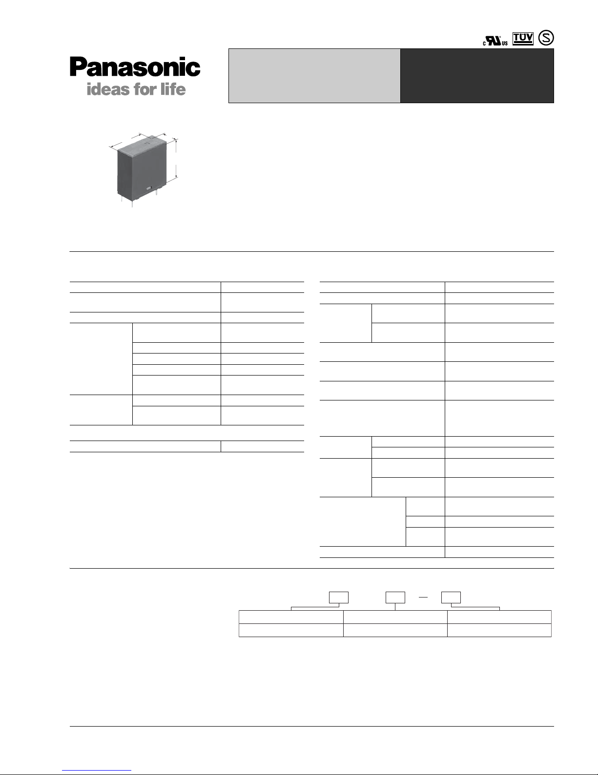
SLIM POWER RELAY
WITH HIGH INRUSH
CURRENT CAPABILITY
TV-8 CERTIFIED
LK-T RELAYS
FEATURES
1. High inrush current capability
1) Operating load capability:
inrush 118 A, steady 8 A
2) UL/C-UL TV-8 approved
2. High insulation resistance
1) Creepage distance and clearances
between contact and coil: Min. 6 mm .236
inch (In compliance with IEC65)
2) Surge withstand voltage between
contact and coil: 10,000 V or more
3. High noise immunity realized by the
card separation st ru cture between
contact and coil
4. Conforms to the various safety
standards
UL, C-UL, TÜV, and SEMKO approved
25.0
24.0
11.0
.984
.945
.433
Contact
Coil
#1 This value can change due to the switching frequency , environmental condi tions,
and desired reliability level, therefore it is recommended to check this with the
actual load.
Remarks
*1Measurement at same location as “Initial breakdown voltage” section.
*
2
Detection current: 10mA
*
3
Wave is standard shock voltage of ±1.2 × 50μs according to JEC-212-1981
*
4
Excluding contact bounce time.
*
5
Half-wave pulse of sine wave: 11 ms; detection time: 10 μs
*
6
Half-wave pulse of sine wave: 6 ms
*
7
Detection time: 10 μs
*
8
The upper operation ambient temperature limit is the maxi mum tempera ture that
can satisfy the coil temperature rise value. Refer to 1. Usage, transport and
storage conditions in NOTES on page 3.
Characteristics
Arrangement 1 Form A
Initial contact resistance
(By voltage drop 6 V DC 1 A)
Max. 100 mΩ
Contact material AgSnO2 type
Rating
(resistive load)
Nominal switching
capacity
5 A 277 V AC
Max. switching power 1,385 V A
Max. switching voltage 277 V AC
Max. switching current 8 A (120V AC)
Min. switching capacity
#1
(Reference value)
100 mA, 5 V DC
Expected life
(min. operations)
Mechanical (at 180 cpm) 10
6
Electrical (at 20 cpm)
(at rated load)
10
5
Nominal operating power 250 mW
Max. operating speed 20 cpm (at rated load)
Initial insulation resistance*
1
Min. 1,000 MΩ (at 500 V DC)
Initial *2
breakdown
voltage
Between open
contacts
1,000 Vrms for 1 min.
Between contact
and coil
4,000 Vrms for 1 min.
Initial surge voltage between contact
and coil*
3
10,000 V
Operate time*
4
(at nominal voltage)
Max. 15ms (at 20°C 68°F)
Release time (without diode)*
4
(at nominal voltage)
Max. 5ms (at 20°C 68°F)
Temperature rise (at 70°C)
Max. 35°C with nominal coil
voltage and at 5 A contact
carrying current
(resistance method)
Shock
resistance
Functional*
5
200 m/s2{approx. 20 G}
Destructive*
6
1,000 m/s2{approx. 100 G}
Vibration
resistance
Functional*
7
10 to 55Hz
at double amplitude of 1.5mm
Destructive
10 to 55Hz
at double amplitude of 1.5mm
Conditions for operation,
transport and storage*
8
(Not freezing and
condensing at low
temperature)
Ambient
temp.
–40°C to +70°C
–40°F to +158°F
Humidity 5 to 85% R.H.
Air
pressure
86 to 106 kPa
Unit weight Approx. 12 g .42 oz
TYPICAL
APPLICATIONS
• Audio visual equipment
• Flat TVs and audio equipment, etc.
• Office equipment
• Home appliances
ORDERING INFORMATION
Contact arrangement Protective construction Coil voltage(DC)
1a: 1 Form A F: Flux-resistant type 5, 9, 12, 24V
Ex. LKT 1a F 12V
UL/C-UL, TÜV, SEMKO, TV-8 approved type is standard.
Notes: 1. Standard packing Carton: 100 pcs. Case: 500 pcs.
2. 3 V, 6 V, and 18 V DC types are also available. Please consult us for details.
LK-T
2
ds_61113_0004_en_lkt: 091008J
TYPES AND COIL DATA (at 20°C 68°F)
DIMENSIONS
mm inch
REFERENCE DATA
Part No.
Nominal voltage,
V DC
Pick-up voltage,
V DC (max.)
(Initial)
Drop-out
voltage,
V DC (min.)
(Initial)
Coil resistance,
Ω (±10%)
Nominal
operating
current, mA
(±10%)
Nominal
operating power,
mW
Maximum
allowable
voltage, V DC
(at 20°C 68°F)
LKT1aF-5V 5 (Initial) 3.5 (Initial) 0.5 100 50 250 6.5
LKT1aF-9V 9 (Initial) 6.3 (Initial) 0.9 324 27.8 250 11.7
LKT1aF-12V 12 (Initial) 8.4 (Initial) 1.2 576 20.8 250 15.6
LKT1aF-24V 24 (Initial) 16.8 (Initial) 2.4 2,304 10.4 250 31.2
4
0.5
1.65
Max. 25.0
Max. 11.0
0.3
0.5 dia.
20.0
16.5
0.4
Max. 24.0
7.5
1.0
.157
.020
.065
.984
.433
.012
.020 dia.
.787
.650
.016
.945
.295
.039
Dimension: General tolerance
Max. 1mm .039 inch: ±0.1 ±.004
1 to 3mm .039 to .118 inch: ±0.2 ±.008
Min. 3mm .118 inch: ±0.3 ±.012
PC board pattern (Bottom view)
Tolerance: ±0.1 ±.004
Schematic (Bottom view)
2-0.9 dia. 2-1.3 dia.
16.5
7.5
20.0
2
-.035 dia. 2-.051 di
a.
.650
.295
.787
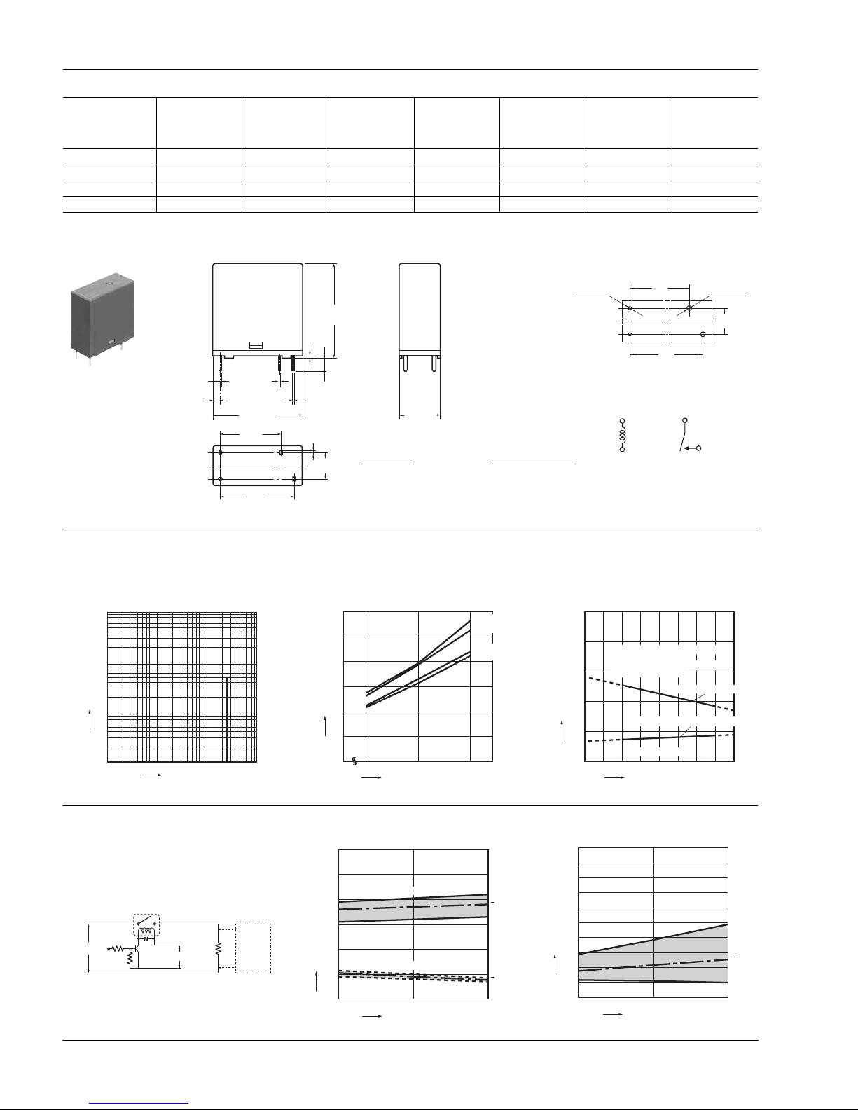
1. Max. switching power (AC resistive load) 2. Coil temperature rise
Sample: LKT1aF-12V, 6 pcs.
Point measured: coil inside
Contact current: 0 A, 5A
3. Ambient temperature characteristics and coil
applied voltage
100
10
1
5
0 10 100
Contact voltage, V
Contact current, A
800
0
5
10
15
20
25
30
100 120
20°C 5A
20°C 0A
70°C 5A
70°C 0A
Temperature rise, °C
Coil applied voltage, %V
0
500
400
300
200
100
0 1020304050607080
Ambient temperature, °C
Allowable ambient temperatures
against % coil voltages
(max. inside the coil temperature
set as 115°C
Pick-up voltage
Coil & contact no carrying current
Coil applied voltage, %V
Carrying current: 5
A
239°F)
4-(1). Electrical life test
(5 A 277 V AC, resistive load)
Sample: LKT1aF-12V, 6 pcs.
Operation frequency: 20 times/min.
(ON/OFF = 1.5s: 1.5s)
Ambient temperature: 20°C 68°F
Circuit:
Change of pick-up and drop-out voltage Change of contact resistance
12V DC
Contact
welding
detection
and Miscontacting
detection
circuit
277V AC
0
0
2
4
6
8
10
12
510
Drop-out voltage
Pick-up voltage
Max.
Min.
x
Max.
Min.
x
No. of operations, ×10
4
Pick-up and drop-out voltage, V
0
0
5
10
15
20
25
30
35
40
45
50
105
Max.
Min.
x
No. of operations, ×10
4
Contact resistance, mΩ
 Loading...