

Panasonic LH-CD6 Installation Manual
INSTRUCTION MANUAL
LED Type Optical Displacement Sensor
High-functionality Controller
1-Head Type
LH-CS6, LH-CS6P
High-functionality Controller
2-Head Type
LH-CD6, LH-CD6P
Thank you very much for using SUNX sensors. Please read this Instruction Manual
carefully and thoroughly for the correct and
optimum use of this sensor. Kindly keep
this manual in a convenient place f or quick
reference.
This product is not a safety
sensor. Its use is not
intended or designed to
protect life and prevent body
injury or property damage
from dangerous parts of
machinery. It is a normal
object detection sensor.
For details, please refer to the User’s
Manual.
— CONTENTS —
z SPECIFICATIONS ....................... 1
x CAUTIONS .................................. 3
c MOUNTING ................................. 3
v CONNECTION ............................. 4
b
n FUNCTIONAL DESCRIPTION .... 8
m SETTING ..................................... 9
, DIMENSIONS ............................ 19
Page
䢇 Connection of sensor
head to controller ...................4
䢇 I/O circuit diagrams ................5
䢇 RS-232C modular connector
pin position ............................7
ANALOG OUTPUT DIAGRAMS
... 7
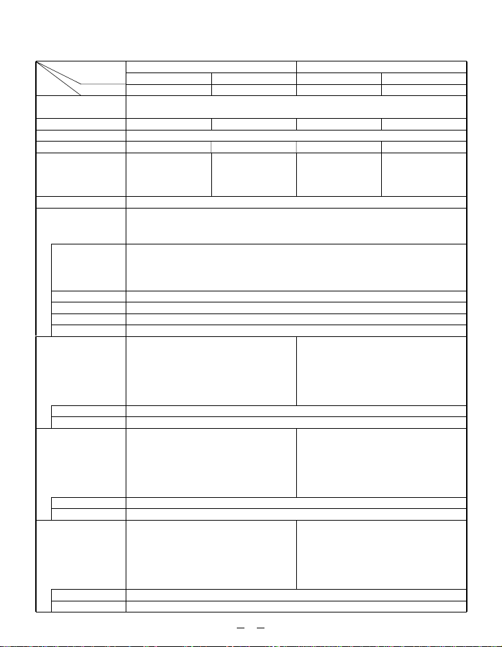
z SPECIFICATIONS
Type
Applicable sensor
head (Note 2)
Connectable sensor heads (Max.)
Supply voltage
Current consumption (Note 3)
Sampling frequency
Gain setting
Analog output
()
Comparative output
(HI, GO, LO)
Strobe output
Alarm output
Model No.Item
Analog voltage output
Analog current output
Response time
(Note 5)
Linearity (Note 6)
Temp. characteristics
Span adjustment
Shift adjustment
Output operation
Short-circuit protection
Output operation
Short-circuit protection
Output operation
Short-circuit protection
NPN open-collector transistor
• Maximum sink current: 30mA
• Applied voltage: 30V DC or less
• Residual voltage:
NPN open-collector transistor
• Maximum sink current: 30mA
• Applied voltage: 30V DC or less
• Residual voltage:
NPN open-collector transistor
• Maximum sink current: 30mA
• Applied voltage: 30V DC or less
• Residual voltage:
NPN output type
1-head type
LH-CS6
1 No.
3.3kHz approx.
Analog voltage Analog current
• Output voltage:
• Output impedance: 100 Ω • Load resistance: 300 Ω or less
When set to SELECT: 0.5ms/1ms/10ms/20ms/30ms/40ms/100ms/300ms
When set to AUTO: 0.5ms/1ms/10ms/20ms/30ms/40ms/100ms/300ms
(between comparative output and 0V)
1.0V or less (at 30mA sink current)
0.4V or less (at 16mA sink current)
(between strobe output and 0V)
1.0V or less (at 30mA sink current)
0.4V or less (at 16mA sink current)
(between alarm output and 0V)
1.0V or less (at 30mA sink current)
0.4V or less (at 16mA sink current)
OFF when DARK, BRIGHT, NEAR, FAR, or other error is displayed.
2-head type
LH-CD6
LH-54, LH-58, LH-512
2 Nos.
24V DC
±
10% Ripple P-P 10% or less
350mA or less 350mA or less300mA or less 300mA or less
When set to CH 1 or CH 2:
•
3.3kHz approx.
•
When set to Calculation:
825Hz approx.
AUTO (Note 4) / SELECT (settable in 11 steps)
–5 to +5V • Output current: 4 to 20mA
selectable by key
automatically selected depending on the measured object
Within
Within
±
Within
Within
±
ON when threshold level is reached
ON when comparative output is effective
Incorporated
Incorporated
1-head type
LH-CS6P
3.3kHz approx.
±
0.2% F.S.
±
0.04% F.S./˚C
30% F.S. (Note 7)
30% F.S. (Note 7)
PNP open-collector transistor
• Maximum source current: 30mA
• Applied voltage: 30V DC or less
(between comparative output and
• Residual voltage:
1.0V or less (at 30mA source current)
0.4V or less (at 16mA source current)
PNP open-collector transistor
• Maximum source current: 30mA
• Applied voltage: 30V DC or less
• Residual voltage:
1.0V or less (at 30mA source current)
0.4V or less (at 16mA source current)
PNP open-collector transistor
• Maximum source current: 30mA
• Applied voltage: 30V DC or less
• Residual voltage:
1.0V or less (at 30mA source current)
0.4V or less (at 16mA source current)
—
1
PNP output type
1 No.
(between strobe output and
(between alarm output and
2-head type
•
When set to CH 1 or CH 2:
•
When set to Calculation:
LH-CD6P
2 Nos.
3.3kHz approx.
825Hz approx.
+V)
+V)
+V)
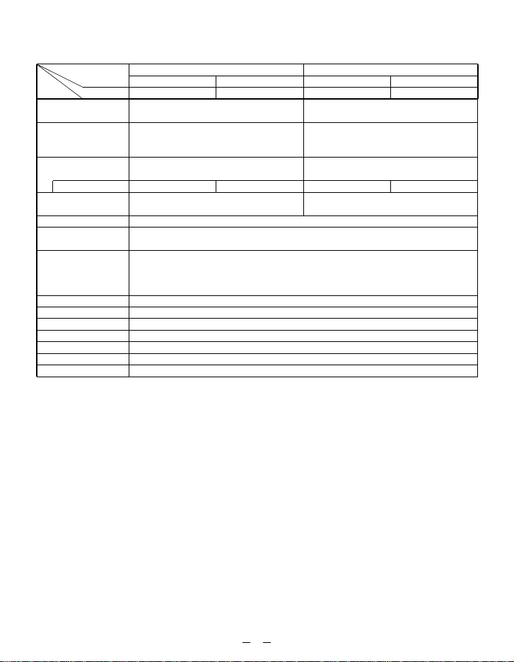
Type
Model No.Item
0-ADJ input
Remote interlock input
BUSY input
No. of inputs
Calculation hold reset
input
Timer function
Interference prevention
function (Note 8)
Serial communication
Display
Ambient temperature
Ambient humidity
Material
Connection method
Weight
Accessory
NPN output type
1-head type
LH-CS6
Low (0 to 1V): 0-ADJ operation
• Applied voltage: 30V DC or less
Low (0 to 1V): Emission
High (
+
V or open): Emission stopped
• Applied voltage: 30V DC or less
Low (0 to 1V): Measurement stopped
• Applied voltage: 30V DC or less
1 ch.
Low (0 to 1V): Calculation result reset
• Applied voltage: 30V DC or less
Incorporated (operates on comparative output and alarm output)
Standard: RS-232C (RD/SD/SG)
Connector: 6 pin modular jack
Operation: user setting external switching, function detail external setting,
0 to
2-head type
LH-CD6
High (
Low (0 to 1V, or open): Emission stopped
• Applied voltage: 30V DC or less
2 ch.
Incorporated (up to two units)
measurement data transmission, etc.
+
50˚C (No dew condensation), Storage: –20 to +60˚C
5 digit red LED display
35 to 85% RH, Storage: 35 to 85% RH
Enclosure: Polycarbonate
Terminal block connection
120g approx.
ATA4811 (Controller mounting frame): 1 set
PNP output type
1-head type
LH-CS6P
High (
+
V): 0-ADJ operation
• Applied voltage: 30V DC or less
+
V): Emission
High (
+
V): Measurement stopped
• Applied voltage: 30V DC or less
1 ch.
+
V): Calculation result reset
High (
• Applied voltage: 30V DC or less
2-head type
LH-CD6P
2 ch.
Notes:
1) Conditions which have not been specified are to be taken as: 24V DC supply voltage,
+20˚C
ambient temperature, SELECT gain setting, 300ms response time setting, center measuring
distance, interference prevention function not used, and white ceramic board object.
2) For details of the applicable sensor head, please refer to the instruction manual of the sensor
head.
3) Including the sensor head.
4) Take care that when the gain is set to AUTO, the linearity and the resolution may deteriorate.
5) For LH-CD6(P), this is the response time for CH 1 or CH 2 setting. The response time for Calculation setting is four times this value. Also, take care that when the response time is set to AUTO,
the linearity, resolution and the response time will vary.
6) This is the value for white ceramic board object. The linearity may differ depending on the measured object. Further, in case of LH-CD6(P), this is the value for CH 1 or CH 2 setting. For
calculation setting, the linearity is approx. twice the value given in the above table.
7) The linearity of the sensor head and the controller has been adjusted at the time of shipment.
Carry out the shift adjustment and the span adjustment to suit the operating conditions.
8) Take care that the linearity, resolution and the response time may deteriorate when the interference prevention function is used.
2
x CAUTIONS
This controller has been designed to meet the specifications when used along with the optional
exclusive sensor heads. In case it is used in a combination that does not use the optional
exclusive sensor heads, not onl y the specifications ma y not be met, b ut it ma y also cause an
accident, etc. Hence, always use this controller along with the exc lusive sensor heads.
䢇 Use this product 30 min. after the power is supplied. Immediately on supply of power,
the electrical circuit is yet to stabilize, which may cause variation in measured values.
䢇 Take care that after switching on the power supply, there is a muting time of 5 sec.
䢇
Make sure to carry out the wiring in the power supply off condition.
䢇 Take care that wrong wiring will damage the sensor.
䢇 Verify that the supply voltage variation is within the rating.
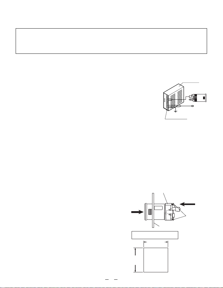
䢇 If power is supplied from a commercial switching regulator,
ensure that the frame ground (F.G.) terminal of the power supply is connected to an actual ground.
䢇
In case noise generating equipment (switching regulator, inverter
motor, etc.) is used in the vicinity of this product, connect the
frame ground (F .G.) terminal of the equipment to an actual ground.
䢇 Do not r un the wires together with high-voltage lines or power lines or put them in
the same raceway. This can cause malfunction due to induction.
䢇 The analog output and the alarm output are not incorporated with a short-circuit pro-
tection circuit. Do not connect them directly to a power supply or a capacitive load.
䢇 Avoid dust, dirt, and steam.
䢇 Take care that the sensor does not come in direct contact with water, oil, grease, or
organic solvents, such as, thinner, etc.
䢇 Mount the controller such that the ventilation holes are not blocked.
䢇 If the controller is used for a long time, although it becomes hot, this does not indi-
cate any abnormality. However, if the controller is used by being enclosed in a control box, make sure to provide for enough heat radiation or cooling by fan, etc.
c MOUNTING
Controller mounting frame (ATA4811) (Accessory)
q Insert the controller, from its rear portion, into
the cut-out of the panel.
q
w Insert the enclosed controller mounting frame
(ATA4811) from the rear side of the controller
and push it till the end.
e Tighten the controller mounting frame uniformly ,
using the mounting screws (2 Nos.) enclosed
with it. After mounting on the panel, make sure
to confirm that the controller is firmly mounted
Panel cut-out dimensions
45±
0.6
0
Panel thickness:
1 to 5mm
mm
and that it does not shake.
Note: If the mounting screws are tightened excessiv ely, the control-
ler mounting frame gets displaced. In case this happens,
loosen the screws once, push in the controller mounting
frame and then tighten the mounting screws.
45±
mm
0.6
0
3
Ground
F.G. terminal
Switching
regulator
w
e
v CONNECTION
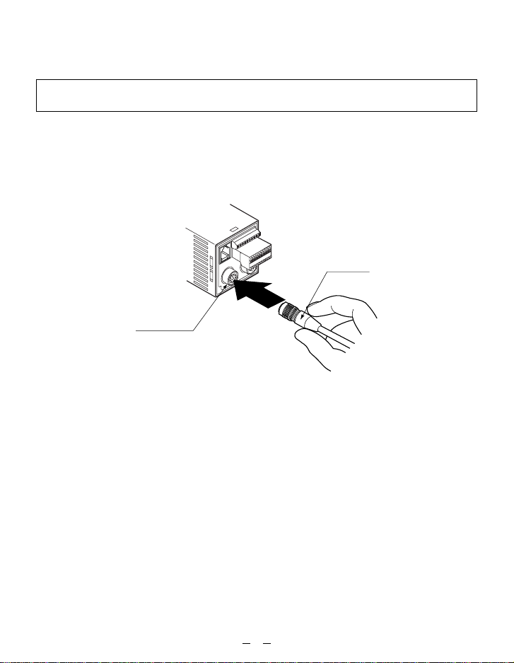
䢇 Connection of sensor head to controller
Make sure to connect or disconnect the connector to the controller in the power
supply off condition.
• One sensor head can be connected to LH-CS6(P), whereas, up to two sensor heads
can be connected to LH-CD6(P).
Hold the sensor head’s connector and insert it into the connector provided on the
controller for sensor head connection. Insert till it locks.
Connector
Connector for
sensor head
※ To remove the sensor head, hold its connector by the outer ring and pull it straight
out. While removing the connector from the controller, take care not to touch the
terminals inside the connector.
(Do not pull by holding the cable, as this can result in cable disconnection.)
4
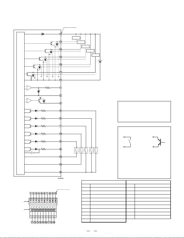
䢇 I/O circuit diagrams
• LH-CS6, LH-CD6/NPN output type
Terminal No.
1
D
T
T
r
2
D3
Z
T
r
3
D4
Z
T
r
4
Z
D5
T
r
5
+
−
+
−
Main circuit
• Terminal arrangement
Upper
terminal
block
Lower
terminal
block
100 Ω
D6
Z
+
12V
Z
D7
4.7kΩ
2
D
4.7kΩ
D
3
4.7kΩ
4
D
4.7kΩ
D
5
4.7kΩ
D
6
4.7kΩ
D
7
Internal circuit
+
V
Comparative
D1
Z
output HI
r
1
Z
30mA max.
D2
Comparative output GO
30mA max.
Comparative output LO
Strobe output
Alarm output
0V
Analog voltage output –5 to
GND for analog output
Analog current output 4 to 20mA (Note 2)
BUSY input HEAD 1
BUSY input HEAD 2 (Note 3)
Calculation hold reset input
0-ADJ input
Remote interlock input
Interference
prevention
I/O (Note 4)
Input COM
Input COM
Input COM
Users’ circuit
Terminal No.
Load
Load
30mA max.
※1
Load
Load
Load
+
24V DC
±
10%
30mA max.
※1
Terminal No.
–
30mA max.
+
5V (Note 1)
※1
※1
※1
Upper terminal block
Description
Analog voltage output
q
GND for analog output
w
Analog current output
e
Interference prevention I/O
r
BUSY input HEAD 1
t
BUSY input HEAD 2 (Note)
y
Calculation hold reset input
u
Input COM
i
Remote interlock input
o
Input COM
!0
Note: Not used in LH-CS6.
5
Notes:
1) The device connected to ‘q
Analog voltage output’ should
have an input impedance of
1MΩ or more.
2) The device connected to ‘e
Analog current output’ should
have a load resistance of
300Ω or less.
3) In case of LH-CS6, terminal
No. y is not used.
4) Do not wire an interference
prevention I/O other than that
of LH-CS6(P) or LH-CD6(P) to
the interference prevention
I/O. Further, do not connect
together two controllers which
have both been set as masters
during interference prevention
setting, as this will cause a
fault.
Symbols
D1:
Reverse supply polarity protection diode
D2 to D7: Input protection diode
ZD1 to ZD7:
Surge absorption zener diode
Tr1 to Tr5: NPN output transistor
※ 1
Non-voltage contact or
NPN open-collector transistor
or
• 0-ADJ input, BUSY input,
Calculation hold reset input
Low (0 to 1V): Effective
High (+V or open): Ineffective
• Remote interlock input
Low (0 to 1V): Emission
High (+V or open): Emission stopped
Lower terminal block
Terminal No.
!1
!2
!3
!4
!5
!6
!7
!8
!9
Description
+
V
0V
Comparative Output HI
Comparative Output GO
Comparative Output LO
Strobe output
Alarm output
Input COM
0-ADJ input
 Loading...