

Page 1
Hybrid IP-PBX
Installation Manual
Model No.
KX-TDA50
Thank you for purchasing a Panasonic Hybrid IP-PBX.
Please read this manual carefully before using this product and save this manual for future use.
KX-TDA50: MPR Version 2.0
SD Logo is
a trademark.
Page 2

System Components
System Components Table
Model Description
Main Unit KX-TDA50 Main Unit
CO Line Cards KX-TDA5180 4-Port Analog Trunk Card (LCOT4)
KX-TDA5193 4-Port Caller ID Card (CID4)
KX-TDA5480 4-Channel VoIP Gateway Card (IP-GW4)
Extension Cards KX-TDA5170 4-Port Hybrid Extension Card (HLC4)
KX-TDA5171 4-Port Digital Extension Card (DLC4)
KX-TDA5172 8-Port Digital Extension Card (DLC8)
KX-TDA5173 4-Port Single Line Telephone Extension Card (SLC4)
KX-TDA5174 8-Port Single Line Telephone Extension Card (SLC8)
KX-TDA5175 4-Port Proprietary Extension Card (PLC4)
KX-TDA5176 8-Port Proprietary Extension Card (PLC8)
Other Cards KX-TDA5105 Memory Expansion Card (MEC)
KX-TDA5161 4-Port Doorphone Card (DPH4)
KX-TDA5166 8-Channel Echo Canceller Card (ECHO8)
KX-TDA5168 Extension Caller ID Card (EXT-CID)
KX-TDA5191 2-Channel Message Card (MSG2)
KX-TDA5196 Remote Card (RMT)
Optional SD Memory Card KX-TDA5920 SD Memory Card for Software Upgrade to Enhanced Version
Cell Station (CS) KX-T0141 2-Channel Cell Station Unit for 2.4 GHz Portable Station
Proprietary Equipment KX-A236 Additional AC Adaptor
KX-T30865 Doorphone
Available Proprietary Telephones
The Hybrid IP-PBX supports Panasonic KX-T7000 and KX-TD7000 series telephones:
• Digital/Analog proprietary telephones (e.g., KX-T7625, KX-T7630, KX-T7633, KX-T7636)
• Portable stations (e.g., KX-TD7690)
• DSS consoles (e.g., KX-T7640)
Note
The Hybrid IP-PBX does not support the following telephones:
• KX-T30800 series Proprietary Telephones and DSS consoles
• KX-T61600 series Proprietary Telephones and DSS consoles
• KX-T123200 series Proprietary Telephones and DSS consoles
2 Installation Manual
Page 3

For the equipment (e.g., Add-on Key Module, USB Module, Headset*1) that can be connected to a particular
telephone, refer to the telephone's manual.
For other equipment that can be connected to the Hybrid IP-PBX, refer to "1.2.2 System Connection
Diagram".
Abbreviations in this manual
Proprietary telephone: PT
Digital proprietary telephone: DPT
Analog proprietary telephone: APT
Portable station: PS
Single line telephone: SLT
*1
The KX-T7090 headset can be connected to the KX-T7000, KX-T7200, KX-T7300, and KX-T7400 series telephones.
Installation Manual 3
Page 4

Important Safety Instructions
SAFETY REQUIREMENTS
When using your telephone equipment, basic safety precautions should always be followed to reduce the
risk of fire, electric shock and injury to persons, including the following:
1. Read and understand all instructions.
2. Follow all warnings and instructions marked on the product.
3. Unplug this product from the wall outlet before cleaning. Do not use liquid cleaners or aerosol cleaners.
Clean with a damp cloth.
4. Do not use this product near water, for example, near a bathtub, wash bowl, kitchen sink, or laundry
tub, in a wet basement, or near a swimming pool.
5. Do not place the product on an unstable surface, as a fall may cause serious internal damage.
6. Slots and openings in the front, back and bottom of the cabinet are provided for ventilation; to protect
it from overheating, these openings must not be blocked or covered. The openings should never be
blocked by placing the product on a bed, sofa, rug, or other similar surface while in use. The product
should never be placed near or over a radiator or other heat source. This product should not be placed
in a sealed environment unless proper ventilation is provided.
7. The product should only be connected to the type of electrical power supply specified on the product
label. If you are not sure of the type of power supply to your home, consult your dealer or local power
company.
8. For safety purposes this unit is equipped with a grounded plug. If you do not have a grounded outlet,
please have one installed. Do not bypass this safety feature by tampering with the plug.
9. Do not allow anything to rest on the power cord. Do not locate this product where the power cord may
be stepped on or tripped on.
10. To reduce the risk of fire or electric shock, do not overload wall outlets and extension cords.
11. Do not insert objects of any kind into this product through its slots and openings, as they may touch
dangerous voltage points or short out parts that could result in a risk of fire or electric shock. Never spill
liquid of any kind on or in the product.
12. To reduce the risk of electric shock, do not disassemble this product. Only qualified personnel should
service this product. Opening or removing covers may expose you to dangerous voltages or other risks.
Incorrect reassembly can cause electric shock.
13. Unplug this product from the wall outlet and have it serviced by qualified service personnel in the
following cases:
a) When the power supply cord or plug is damaged or frayed.
b) If liquid has been spilled into the product.
c) If the product has been exposed to rain or water.
d) If the product does not operate according to the operating instructions. Adjust only the controls that
are explained in the operating instructions. Improper adjustment of other controls may result in
damage and may require service by a qualified technician to restore the product to normal
operation.
e) If the product has been dropped or the cabinet has been damaged.
f) If product performance deteriorates.
14. Avoid using wired telephones during an electrical storm. There is a remote risk of electric shock from
lightning.
15. Do not use a telephone in the vicinity of a gas leak to report the leak.
4 Installation Manual
Page 5

SAVE THESE INSTRUCTIONS
Installation Manual 5
Page 6

Precaution
WARNING
DO NOT REMOVE
SD MEMORY CARD
WHILE POWER IS
SUPPLIED TO THE
HYBRID. IP-PBX
Doing so may cause the Hybrid IP-PBX
to fail to start when you restart the
system.
6 Installation Manual
Page 7

• Keep the unit away from heating appliances and devices that generate electrical noise such as
fluorescent lamps, motors and televisions. These noise sources can interfere with the performance of
the Hybrid IP-PBX.
• This unit should be kept free of dust, moisture, high temperature (more than 40 °C [104 °F]) and
vibration, and should not be exposed to direct sunlight.
• If you are having problems making calls to outside destinations, follow this procedure to test the CO
lines:
1. Disconnect the Hybrid IP-PBX from all CO lines.
2. Connect known working SLTs to those CO lines.
3. Make a call to an external destination using those SLTs.
If a call cannot be carried out correctly, there may be a problem with the CO line that the SLT is
connected to. Contact your telephone company.
If all SLTs operate properly, there may be a problem with your Hybrid IP-PBX. Do not reconnect the
Hybrid IP-PBX to the CO lines until it has been serviced by an authorized Panasonic Factory
Servicenter.
• Wipe the unit with a soft cloth. Do not clean with abrasive powders or with chemical agents such as
benzene or thinner.
WARNING
• THIS UNIT MAY ONLY BE INSTALLED AND SERVICED BY QUALIFIED SERVICE
PERSONNEL.
• IF DAMAGE TO THE UNIT EXPOSES ANY INTERNAL PARTS, DISCONNECT THE
POWER SUPPLY CORD IMMEDIATELY AND RETURN THE UNIT TO YOUR DEALER.
• UNPLUG THIS UNIT FROM THE AC OUTLET IF IT EMITS SMOKE, AN ABNORMAL
SMELL OR MAKES UNUSUAL NOISE. THESE CONDITIONS CAN CAUSE FIRE OR
ELECTRIC SHOCK. CONFIRM THAT SMOKE HAS STOPPED AND CONTACT AN
AUTHORIZED PANASONIC FACTORY SERVICENTER.
• WHEN RELOCATING THE EQUIPMENT, FIRST DISCONNECT THE TELECOM
CONNECTION BEFORE DISCONNECTING THE POWER CONNECTION. WHEN THE
UNIT IS INSTALLED IN THE NEW LOCATION, RECONNECT THE POWER FIRST,
AND THEN RECONNECT THE TELECOM CONNECTION.
• TO PREVENT POSSIBLE FIRE OR ELECTRIC SHOCK, DO NOT EXPOSE THIS
PRODUCT TO RAIN OR MOISTURE.
• THE POWER SUPPLY CORD IS USED AS THE MAIN DISCONNECT DEVICE.
ENSURE THAT THE AC OUTLET IS LOCATED NEAR THE EQUIPMENT AND IS
EASILY ACCESSIBLE.
CAUTION
DANGER OF EXPLOSION EXISTS IF A BATTERY IS INCORRECTLY REPLACED. REPLACE ONLY
WITH THE SAME OR EQUIVALENT TYPE RECOMMENDED BY THE BATTERY MANUFACTURER.
DISPOSE OF USED BATTERIES ACCORDING TO THE MANUFACTURER'S INSTRUCTIONS.
Installation Manual 7
Page 8

When you ship the product
Carefully pack and send it prepaid, adequately insured and preferably in the original carton. Attach a
postage-paid letter, detailing the symptom, to the outside of the carton. DO NOT send the product to the
Executive or Regional Sales offices. They are NOT equipped to make repairs.
Product Service
Panasonic Factory Servicenters for this product are listed in the servicenter directory. Consult your certified
Panasonic dealer for detailed instructions.
For Future Reference
Please print, record, and retain the following information for future reference.
Note
The serial number of this product can be found on the label affixed to the unit. You should record the
model number and the serial number of this unit as a permanent record of your purchase to aid in
identification in the event of theft.
MODEL NO.
SERIAL NO.
DATE OF PURCHASE
NAME OF DEALER
DEALER'S ADDRESS
DEALER'S TEL. NO.
8 Installation Manual
Page 9

Introduction
This Installation Manual is designed to serve as an overall technical reference for the Panasonic Hybrid IPPBX, KX-TDA50. It provides instructions for installing the hardware, and programming the Hybrid IP-PBX
using the KX-TDA50 Maintenance Console.
The Structure of this Manual
This manual contains the following sections:
Section 1 System Outline
Provides general information on the Hybrid IP-PBX, including the system capacity and specifications.
Section 2 Installation
Describes the procedures to install the Hybrid IP-PBX. Detailed instructions for planning the installation
site, installing the optional service cards, and cabling of peripheral equipment are provided. Further
information on system expansion and peripheral equipment installation is included.
Section 3 Guide for the Hybrid IP-PBX PC Programming Software
Explains the installation procedure, structure, and basic information of the KX-TDA50 Maintenance
Console.
Section 4 Troubleshooting
Provides information on the Hybrid IP-PBX and telephone troubleshooting.
About the Other Manuals
Along with this Installation Manual, the following manuals are available:
Feature Guide
Describes all basic, optional and programmable features of the Hybrid IP-PBX, and step-by-step
instruction for performing system programming using a proprietary telephone or a personal computer
(PC).
User Manual
Provides operating instructions for end users using a PT, SLT, PS, or DSS Console.
Trademarks
• Microsoft and Windows are either registered trademarks or trademarks of Microsoft Corporation in
the United States and/or other countries.
• Intel and Pentium are trademarks or registered trademarks of Intel Corporation or its subsidiaries
in the United States and other countries.
• All other trademarks identified herein are the property of their respective owners.
• Screen shots reprinted with permission from Microsoft Corporation.
Installation Manual 9
Page 10

F.C.C. REQUIREMENTS AND RELEVANT INFORMATION
1. Notification to the Telephone Company
This equipment complies with Part 68 of the FCC rules and the requirements adopted by the ACTA. On
the side of this equipment is a label that contains, among other information, a product identifier in the
format US: ACJMF03AKX-TDA50. If requested, this number must be provided to the telephone
company.
Installation must be performed by a qualified professional installer. If required, provide the telephone
company with the following technical information:
• Telephone numbers to which the system will be connected
• Make: Panasonic
• Model: KX-TDA50
• Certification No.: found on the side of the unit
• Ringer Equivalence No.: 0.3A
• Facility Interface Code: 02LS2
• Service Order Code: 9.0F
• Required Network Interface Jack: RJ11
2. Ringer Equivalence Number (REN)
The REN is used to determine the number of devices that may be connected to a telephone line.
Excessive RENs on a telephone line may result in the devices not ringing in response to an incoming
call. In most, but not all areas, the sum of RENs should not exceed five (5.0). To be certain of the
number of devices that may be connected to a line, as determined by the total RENs, contact the local
telephone company. The REN for this product is part of the product identifier that has the format US:
ACJMF03AKX-TDA50. The digits represented by 03 are the REN without a decimal point (e.g., 03 is a
REN of 0.3). For earlier products, the REN is separately shown on the label.
3. Incidence of Harm to the Telephone Lines
If this equipment causes harm to the telephone network, the telephone company will notify you in
advance that temporary discontinuance of service may be required. But if advance notice isn't practical,
the telephone company will notify the customer as soon as possible. Also, you will be advised of your
right to file a complaint with the FCC if you believe it is necessary.
4. Changes in Telephone Company Communications Facilities, Equipment, Operations and
Procedures
The telephone company may make changes in its facilities, equipment, operations or procedures that
could affect the operation of the equipment. If this happens the telephone company will provide
advance notice in order for you to make necessary modifications to maintain uninterrupted service.
5. Trouble with this equipment
If trouble is experienced with this equipment, for repair or warranty information, please see the attached
warranty, which includes the Servicenter Directory. If the equipment is causing harm to the telephone
network, the telephone company may request that you disconnect the equipment until the problem is
resolved.
6. Connection to Party Line
Connection to party line service is subject to state tariffs. Contact the state public utility commission,
public service commission or corporation commission for information.
10 Installation Manual
Page 11

7. Combined Use with Alarm Equipment
If your home has specially wired alarm equipment connected to the telephone line, ensure the
installation of this equipment does not disable your alarm equipment. If you have questions about what
will disable alarm equipment, consult your telephone company or a qualified installer.
Note
This equipment has been tested and found to comply with the limits for a Class B digital device,
pursuant to Part 15 of the FCC Rules. These limits are designed to provide reasonable protection
against harmful interference in a residential installation. This equipment generates, uses, and can
radiate radio frequency energy and, if not installed and used in accordance with the instructions, may
cause harmful interference to radio communications. However, there is no guarantee that interference
will not occur in a particular installation. If this equipment does cause harmful interference to radio or
television reception, which can be determined by turning the equipment off and on, the user is
encouraged to try to correct the interference by one or more of the following measures:
• Reorient or relocate the receiving antenna.
• Increase the separation between the equipment and receiver.
• Connect the equipment into an outlet on a circuit different from that to which the receiver is
connected.
• Consult the dealer or an experienced radio/TV technician for help.
CAUTION
Any changes or modifications not expressly approved by the party responsible for compliance could
void the user's authority to operate this device.
When programming emergency numbers and/or making test calls to emergency numbers:
1. Remain on the line and briefly explain to the dispatcher the reason for the call before hanging up.
2. Perform such activities in the off-peak hours, such as early morning hours or late evenings.
WARNING
The software contained in the ARS and TRS features to allow user access to the
network must be upgraded to recognize newly established network area codes and
exchange codes as they are placed into service. Failure to upgrade the on-premise
PBXs or peripheral equipment to recognize the new codes as they are established will
restrict the customer and users of the PBX from gaining access to the network and to
these codes.
KEEP THE SOFTWARE UP TO DATE WITH THE LATEST DATA.
Installation Manual 11
Page 12

For Cell Station
CAUTION
Any changes or modifications not expressly approved by the party responsible for compliance could
void user's authority to operate this device.
Note
This equipment has been tested and found to comply with the limits for a Class B digital device,
pursuant to Part 15 of the FCC Rules. These limits are designed to provide reasonable protection
against harmful interference in a residential installation. This equipment generates, uses, and can
radiate radio frequency energy and, if not installed and used in accordance with the instructions, may
cause harmful interference to radio communications. However, there is no guarantee that interference
will not occur in a particular installation. If this equipment does cause harmful interference to radio or
television reception, which can be determined by turning the equipment off and on, the user is
encouraged to try to correct the interference by one or more of the following measures:
• Reorient or relocate the receiving antenna.
• Increase the separation between the equipment and receiver.
• Connect the equipment into an outlet on a circuit different from that to which the receiver is
connected.
• Consult the dealer or an experienced radio/TV technician for help.
Some wireless telephones operate at frequencies that may cause interference to nearby TVs and
VCRs. To minimize or prevent such interference, the base of the wireless telephone should not be
placed near or on top of a TV or VCR. If interference is experienced, move the wireless telephone
further away from the TV or VCR. This will often reduce, or eliminate, interference.
Operating near 2.4 GHz electrical appliances may cause interference. Move away from the electrical
appliances.
CAUTION
To comply with FCC RF exposure requirements in uncontrolled environment:
• This equipment must be installed and operated in accordance with provided instructions and a
minimum 20 cm (8 in) spacing must be provided between antenna and all person's body (excluding
extremities of hands, wrist and feet) during wireless modes of operation.
• This transmitter must not be co-located or operated in conjunction with any other antenna or
transmitter.
Medical—consult the manufacturer of any personal medical devices, such as pacemakers, to
determine if they are adequately shielded from external RF (radio frequency) energy. (The unit operates
in the frequency range of 2401 MHz to 2480 MHz, and the power output level can range from 0.004 W
to 0.4 W.) Do not use the unit in health care facilities if any regulations posted in the area instruct you
not to do so. Hospitals or health care facilities may be using equipment that could be sensitive to
external RF (radio frequency) energy.
12 Installation Manual
Page 13

Table of Contents
1 System Outline ..................................................................................... 15
1.1 System Highlights .......................................................................................................... 16
1.1.1 System Highlights ............................................................................................................. 16
1.2 Basic System Construction ........................................................................................... 18
1.2.1 Main Unit........................................................................................................................... 18
1.2.2 System Connection Diagram ............................................................................................ 19
1.3 Options ............................................................................................................................ 21
1.3.1 Options ............................................................................................................................. 21
1.4 Specifications .................................................................................................................23
1.4.1 General Description .......................................................................................................... 23
1.4.2 Characteristics .................................................................................................................. 25
1.4.3 System Capacity...............................................................................................................26
2 Installation............................................................................................. 29
2.1 Before Installation........................................................................................................... 30
2.1.1 Before Installation ............................................................................................................. 30
2.2 Installation of the Hybrid IP-PBX................................................................................... 32
2.2.1 Unpacking......................................................................................................................... 32
2.2.2 Names and Locations ....................................................................................................... 33
2.2.3 Opening/Closing the Covers.............................................................................................34
2.2.4 Installation of the SD Memory Card.................................................................................. 37
2.2.5 Frame Ground Connection ............................................................................................... 38
2.2.6 Installing/Removing the Optional Service Cards .............................................................. 39
2.2.7 Types of Connectors ......................................................................................................... 49
2.2.8 Wall Mounting (KX-TDA50)............................................................................................... 50
2.2.9 Wall Mounting (AC Adaptor) ............................................................................................. 53
2.2.10 Surge Protector Installation ..............................................................................................56
2.3 Installation of the CO Line Cards .................................................................................. 59
2.3.1 LCOT4 Card...................................................................................................................... 59
2.3.2 CID4 Card ......................................................................................................................... 60
2.3.3 IP-GW4 Card .................................................................................................................... 61
2.4 Installation of the Extension Cards...............................................................................63
2.4.1 HLC4 Card ........................................................................................................................ 63
2.4.2 DLC4 Card ........................................................................................................................ 64
2.4.3 SLC4 Card ........................................................................................................................ 65
2.4.4 PLC4 Card ........................................................................................................................ 66
2.4.5 DLC8 Card ........................................................................................................................ 67
2.4.6 SLC8 Card ........................................................................................................................ 68
2.4.7 PLC8 Card ........................................................................................................................ 69
2.5 Installation of the Other Cards ...................................................................................... 70
2.5.1 DPH4 Card .......................................................................................................................70
2.5.2 ECHO8 Card..................................................................................................................... 73
2.5.3 MSG2 Card ....................................................................................................................... 74
2.5.4 EXT-CID Card ................................................................................................................... 75
2.5.5 MEC Card ......................................................................................................................... 76
2.5.6 RMT Card ......................................................................................................................... 78
2.6 Connection of Extensions.............................................................................................. 80
Installation Manual 13
Page 14

2.6.1 Maximum Cabling Distances of the Extension Wiring (Twisted Cable).............................80
2.6.2 Parallel Connection of the Extensions ..............................................................................82
2.6.3 Digital EXtra Device Port (Digital XDP) Connection..........................................................84
2.6.4 First Party Call Control CTI Connection ............................................................................86
2.7 Connection of 2.4 GHz Portable Stations .....................................................................87
2.7.1 Overview ........................................................................................................................... 87
2.7.2 Procedure Overview..........................................................................................................88
2.7.3 Site Planning ..................................................................................................................... 90
2.7.4 Before Site Survey ............................................................................................................94
2.7.5 Site Survey........................................................................................................................96
2.7.6 After Site Survey ............................................................................................................. 100
2.7.7 Connecting a Cell Station to the Hybrid IP-PBX .............................................................101
2.7.8 Wall Mounting ................................................................................................................. 107
2.8
2.8.1 Connection of Doorphones, Door Openers, External Sensors, and External Relays .....109
2.9 Connection of Peripherals ...........................................................................................113
2.9.1 Connection of Peripherals............................................................................................... 113
2.10 Power Failure Connections .......................................................................................... 117
2.10.1 Power Failure Connections ............................................................................................. 117
2.11 Starting the Hybrid IP-PBX........................................................................................... 118
2.11.1 Starting the Hybrid IP-PBX .............................................................................................118
Connection of Doorphones, Door Openers, External Sensors, and External Relays
.... 109
3 Guide for the Hybrid IP-PBX PC Programming Software ............... 123
3.1 Overview ........................................................................................................................124
3.1.1 Overview ......................................................................................................................... 124
3.2 Connection ....................................................................................................................125
3.2.1 Connection...................................................................................................................... 125
3.3 Installation of the Hybrid IP-PBX PC Programming Software ..................................127
3.3.1 Installing and Starting the KX-TDA50 Maintenance Console..........................................127
4 Troubleshooting.................................................................................. 133
4.1 Troubleshooting ............................................................................................................134
4.1.1 Installation ....................................................................................................................... 134
4.1.2 Connection...................................................................................................................... 136
4.1.3 Operation ........................................................................................................................ 138
4.1.4 Using the Reset Button ...................................................................................................140
4.1.5 Troubleshooting by Error Log .......................................................................................... 141
5 Appendix ............................................................................................. 151
5.1 Revision History............................................................................................................ 152
5.1.1 MPR Version 1.1 .............................................................................................................152
5.1.2 MPR Version 2.0 .............................................................................................................153
Index .......................................................................................................... 155
14 Installation Manual
Page 15

Section 1
System Outline
This section provides general information on the Hybrid IPPBX, including the system capacity and specifications.
Installation Manual 15
Page 16

1.1 System Highlights
1.1 System Highlights
1.1.1 System Highlights
Networking Features
The Hybrid IP-PBX supports the following private networking features:
TIE Line Service
PBXs can be connected via a privately leased telephone lines forming a private network. These "TIE
lines" provide a cost-effective way to route calls and communications, and are often used to connect
corporate offices located in different cities.
QSIG Support
TIE line service can be used on a private network that implements the QSIG protocol (Q.931). QSIG
offers TIE line service as well as advanced caller and called party identification features.
Voice over Internet Protocol (VoIP) Network
The Hybrid-IP PBX can be used on a private network which implements VoIP. On this type of network,
information is sent over the private network in IP packets, which allows voice as well as data to be sent
to other devices in the private network.
Built-in Small Call Center Features
Extensions can form an incoming call distribution (ICD) group and be used as a small call center which can
take advantage of several features, some of which are highlighted below.
Queuing
When all available extensions in an ICD group are busy, additional calls can be placed in a queue as
they arrive. While calls are waiting in the queue, callers can hear background music (BGM), an outgoing
message (OGM), etc.
Log-in/Log-out
Members of an ICD group can log-in to or log-out of a group manually. Group members can log-in at
the beginning of a work shift, and log-out at the end of the day. While logged-in, ICD group members
can be allotted a specified amount of time after completing a call during which new calls will not be
received by their extensions, allowing them to finish any necessary paperwork before being eligible to
receive new calls (Wrap-up).
VIP Call
The VIP Call feature is one method of making sure that calls from preferred customers or callers are
answered quickly. When using VIP Call mode, ICD groups are assigned a priority, allowing calls in
higher-priority groups to be answered before calls in lower-priority groups.
Computer Telephony Integration (CTI) Features
Computers can be connected to the Hybrid-IP PBX to provide extension users with access to advanced
features such as pop-up display of caller information, computer-based speed dialing, etc.
PC Phone/PC Console
These Panasonic CTI applications can be used on computers connected to each extension, providing
their respective extension users with powerful and flexible call handling and display features.
16 Installation Manual
Page 17

1.1 System Highlights
Third Party CTI Applications
The Hybrid IP-PBX supports industry standard protocols, allowing third-party CTI applications to be
integrated with the Hybrid-IP PBX and its extensions.
Voice Mail Features
A Voice Processing System (VPS) can be connected to the Hybrid IP-PBX to provide Voice Mail (VM) and
Automated Attendant (AA) services. A Panasonic VPS which supports DPT (Digital) Integration can be
connected to the Hybrid IP-PBX effortlessly and with minimal setup required. Conventional DTMF (analog)
voice mail systems, including those from other manufacturers, are also supported.
Paralleled Telephone Features
By connecting telephones in parallel, you can increase the number of telephones connected to the HybridIP PBX without adding additional extension cards.
Parallel Mode
An SLT can be connected to an APT or DPT which is connected to a Super Hybrid Port of the HybridIP PBX. The SLT shares the same extension number with the APT or DPT.
EXtra Device Port (XDP) Mode
An SLT can be connected to a DPT which is connected to a Super Hybrid Port of the Hybrid-IP PBX.
Unlike parallel mode, XDP mode allows each telephone to act as an independent extension with its own
extension number.
Digital XDP
A DPT can be connected to another DPT which is connected to a DPT port or a Super Hybrid Port of
the Hybrid-IP PBX. Similar to XDP mode, each DPT acts as an independent extension with its own
extension number.
Portable Station (PS) Features
A Panasonic PS can be used in place of a PT to provide wireless access to PBX features and call handling.
When in Wireless XDP Parallel Mode, a PS can share an extension number with a wired telephone, allowing
extension users to use their PSs when they are away from their desks to answer or make calls as if they
were using their wired telephones.
Hospitality Features
This Hybrid IP-PBX has several features that support its use in a hotel-type environment. Extensions
corresponding to guest rooms can be "checked in" or "checked out" by a designated hotel operator, who can
also check or set wake-up calls.
Installation Manual 17
Page 18
1.2 Basic System Construction
1.2 Basic System Construction
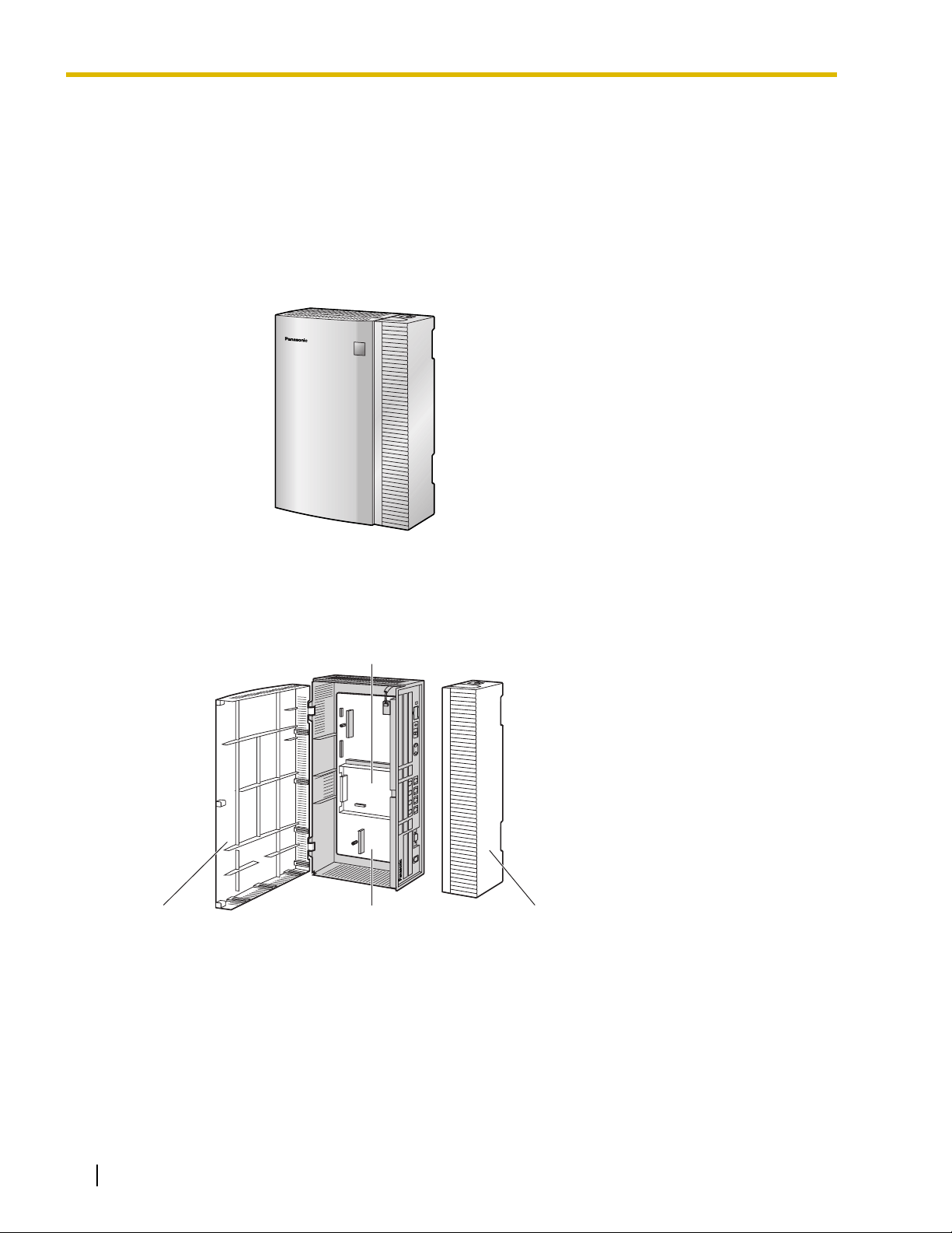
1.2.1 Main Unit
The main unit is equipped with 4 analog trunk ports (one LCOT4 card) and 4 extension ports (Super Hybrid
Ports). For system expansion, optional service cards can be installed, and an additional AC adaptor can
also be connected.
Construction of Main Unit
LCOT4 card
(installed by default)
Front Cover Cable Cover
Main Board
18 Installation Manual
Page 19
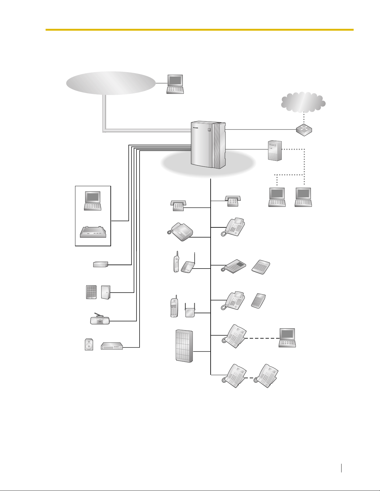
1.2.2 System Connection Diagram
1.2 Basic System Construction
CO (Telephone Company) Lines
Analog
PC
Printer
Remote PC
SLT
Fax Machine
Hybrid IP-PBX
SLT
DPT
Private
IP Network
Router
CTI Server
PC PC
External Sensor/
External Relay Device
Doorphone & Door Opener
BGM/Music On Hold (MOH)
Pager/
Speaker
Amplifier
Wireless Phone
CSPS
Voice Processing
System
APT DSS Console
DPT
DSS Console
USB
KX-T7636/
KX-T7633
KX-T7600 DPT KX-T7600 DPT
PC
Installation Manual 19
Page 20
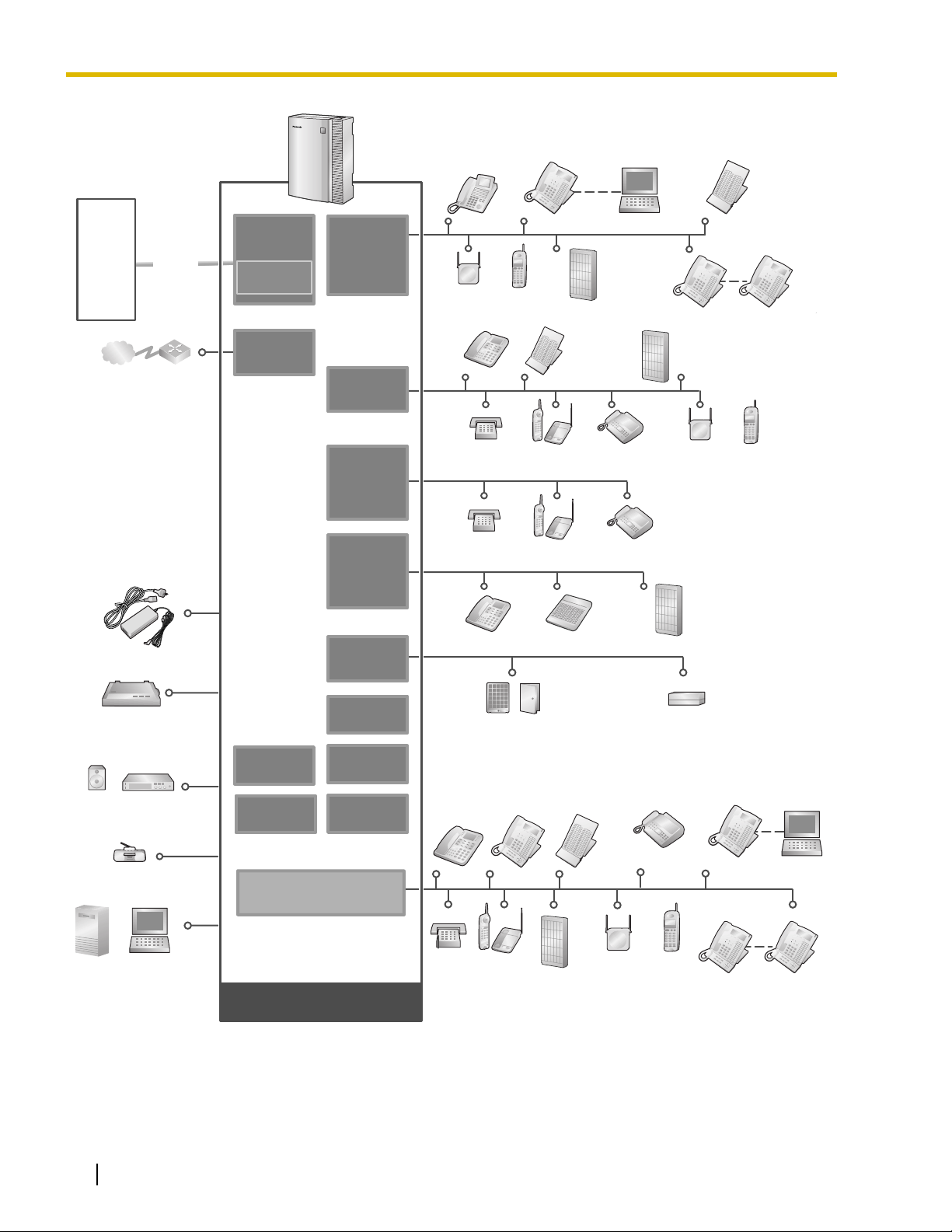
1.2 Basic System Construction
Hybrid IP-PBX
Telephone
Company
Private
IP Network
AC Cord & AC Adaptor
Analog
CO Line
Router
*
2
1
LCOT4
*
(KX-TDA5180)
CID4
(KX-TDA5193)
IP-GW4
(KX-TDA5480)
DLC8
(KX-TDA5172)
DLC4
(KX-TDA5171)
HLC4
(KX-TDA5170)
SLC8
(KX-TDA5174)
SLC4
(KX-TDA5173)
PLC8
(KX-TDA5176)
PLC4
(KX-TDA5175)
DPH4
(KX-TDA5161)
DPT
PT-interface CS PS
APT DSS Console
SLT Wireless Phone Fax Machine
SLT Wireless Phone Fax Machine
APT
PCKX-T7636/KX-T7633 DSS
Voice
Processing
System
DSS Console
Console
KX-T7600 DPT
Voice
Processing
System
PT-interface CS PS
Voice
Processing
System
KX-T7600 DPT
Station Message
Detail Recording (SMDR)
Pager/
Speaker
CTI Server
Amplifier
Radio
PC
MEC
(KX-TDA5105)
RMT
(KX-TDA5196)
4 Super Hybrid Ports
Main Board
ECHO8
(KX-TDA5166)
EXT-CID
(KX-TDA5168)
MSG2
(KX-TDA5191)
3
*
Doorphone & Door Opener
APT DPT
SLT Wireless
Phone
Voice
Processing
System
External Sensor/External Relay Device
DSS
Console
PT-interface CS PS
Fax
Machine
KX-T7636/
KX-T7633
KX-T7600 DPT KX-T7600 DPT
*1 One LCOT4 card is installed by default.
*2 In addition to the supplied AC adaptor, an additional AC adaptor can be connected to the Hybrid IP-
PBX.
*3 The Hybrid IP-PBX has 4 Super Hybrid Ports pre-installed.
PC
20 Installation Manual
Page 21

1.3 Options
1.3.1 Options
1.3 Options
Model No. Model Name Description
KX-TDA5105 Memory Expansion Card
(MEC)
KX-TDA5161 4-Port Doorphone Card
(DPH4)
KX-TDA5166 8-Channel Echo Canceller
Card (ECHO8)
KX-TDA5168 Extension Caller ID Card
(EXT-CID)
KX-TDA5170 4-Port Hybrid Extension
Card (HLC4)
KX-TDA5171 4-Port Digital Extension
Card (DLC4)
KX-TDA5172 8-Port Digital Extension
Card (DLC8)
Memory expansion card to increase Personal/
System Speed Dialing number storage space,
double the number of DPTs (using Digital XDP
connection), and display language selection for
VM Menu. To be installed in the MEC slot.
4-port doorphone card for 4 doorphones, 4 door
openers or external relays, and 4 external
sensors.
8-channel card for echo cancellation during
conferences.
Sends Caller ID signals to extension ports. 1
4-port extension card for SLTs, APTs, DSS
consoles, a Voice Processing System (VPS),
and PT-interface CSs.
4-port digital extension card for DPTs, DSS
consoles, a VPS, and PT-interface CSs.*
8-port digital extension card for DPTs, DSS
consoles, a VPS, and PT-interface CSs.*
*1
Maximum
Quantity
1
1
1
1
1
1
2
1
KX-TDA5173 4-Port Single Line
Telephone Extension Card
(SLC4)
KX-TDA5174 8-Port Single Line
Telephone Extension Card
(SLC8)
KX-TDA5175 4-Port Proprietary
Extension Card (PLC4)
KX-TDA5176 8-Port Proprietary
Extension Card (PLC8)
KX-TDA5180 4-Port Analog Trunk Card
(LCOT4)
KX-TDA5191 2-Channel Message Card
(MSG2)
KX-TDA5193 4-Port Caller ID Card
(CID4)
4-port extension card for SLTs. 1
8-port extension card for SLTs. 2
4-port extension card for APTs, DSS consoles,
and a VPS.
8-port extension card for APTs, DSS consoles,
and a VPS.
4-port analog CO line card with 2 power failure
transfer (PFT) ports.
2-channel message card. 2
4-port Caller ID signal type FSK/FSK (with Call
Waiting Caller ID [Visual Caller ID])/DTMF. To
be mounted on the LCOT4 card.
Installation Manual 21
2
1
2
*2
3
Page 22

1.3 Options
Model No. Model Name Description
Maximum
Quantity
KX-TDA5196 Remote Card (RMT) Analog modem card for remote communication
with the Hybrid IP-PBX. ITU-T V.90 support.
KX-TDA5480 4-Channel VoIP Gateway
Card (IP-GW4)
4-channel VoIP gateway card. Compliant with
VoIP H.323 V.2 protocol, and ITU-T G.729a,
G.723.1, and G.711 CODEC methods.
KX-TDA5920 SD Memory Card for
Software Upgrade to
Enhanced Version
Optional SD Memory Card to upgrade the
Hybrid IP-PBX with MPR version 1 or 1.1 to
version 2.0, and for NDSS feature and CTI
enhancement.
KX-A236 Additional AC Adaptor AC adaptor and AC cord for system expansion. 1
*1
The PT-interface CS can be connected to the Hybrid IP-PBX using a cable like a PT.
*2
One LCOT4 card is installed by default. Two more LCOT4 cards can be optionally installed in the Hybrid IP-PBX.
1
1
1
22 Installation Manual
Page 23

1.4 Specifications
1.4.1 General Description
Switching Non-blocking
AC Adaptor AC Input 100 V AC to 240 V AC, 1.5 A, 50 Hz/60 Hz
DC Output 40 V, 1.38 A (55.2 W)
DC Input • DC IN 1: 40 V, 1.38 A (55.2 W)
• DC IN 2: 40 V, 1.38 A (55.2 W)
Maximum Power Failure Tolerance 300 ms
Memory Backup Duration 7 years
Dialing CO Line Dial Pulse (DP) 10 pps, 20 pps
Tone (DTMF) Dialing
Extension Dial Pulse (DP) 10 pps, 20 pps
Tone (DTMF) Dialing
1.4 Specifications
Connectors CO Line RJ11 (2 wire) × each CO ports
Extension RJ11 (4 wire) × each extension ports
Paging Output 1 conductor jack
External MOH
(Music on Hold)
Output
Mode Conversion DP-DTMF, DTMF-DP
Ring Frequency 20 Hz/25 Hz (selectable)
Central Office Loop Limit 1600 Ω maximum
Operating
Environment
Conference Call CO Line From 10 × 3-party conference call to 4 × 8-party conference call
Music on Hold 1 port (Level Control: -11 dB to +11 dB in 1 dB steps)
Paging Internal Level Control: -15 dB to +6 dB in 3 dB steps
Serial Interface
Port
Tem perature 0 °C to 40 °C (32 °F to 104 °F)
Humidity 10 % to 90 % (non-condensing)
External 1 port (Volume Control: -15 dB to +15 dB in 1 dB steps)
RS-232C 1 (maximum 115.2 kbps)
USB 1
1 conductor jack
Selectable Tone/External Music Source port
Installation Manual 23
Page 24

1.4 Specifications
Extension Connection Cable SLT 1-pair wire (T, R)
DPT 1-pair wire (D1, D2) or
2-pair wire (T, R, D1, D2)
APT 2-pair wire (T, R, D1, D2)
PT-interface CS 1-pair wire (D1, D2)
DSS Console and Add-on Key Module 1-pair wire (D1, D2)
Dimension 275 mm (W) × 376 mm (H) × 117 mm (D)
(10-4/5 in × 14-4/5 in × 4-3/5 in)
Weight (when fully mounted) Under 3.5 kg (7.72 lb)
24 Installation Manual
Page 25

1.4 Specifications
1.4.2 Characteristics
Terminal Equipment Loop Limit • PT: KX-T7600 series: 90 Ω; all other DPTs/APTs: 40 Ω
• SLT: 600 Ω including set
• Doorphone: 20 Ω
• PT-interface CS: 65 Ω
Minimum Leakage Resistance 15 000 Ω minimum
Maximum Number of Extension
Instruments per Line
Ring Voltage 75 Vrms at 20 Hz/25 Hz depending on the Ringing Load
Central Office Loop Limit 1600 Ω maximum
Hookswitch Flash Timing Range 24 ms to 2032 ms
Door Opener Current Limit 24 V DC/30 V AC, 1 A maximum
External Relay Current Limit 24 V DC/30 V AC, 1 A maximum
External Sensor Current Limit Power to the external sensor is provided from the DPH4 card and must be
Paging Terminal Impedance 600 Ω
MOH Terminal Impedance 10 000 Ω
1 for PT or SLT
2 by Parallel or eXtra Device Port connection of a PT and an SLT
3 by Digital eXtra Device Port connection of two DPTs and an SLT
grounded through the DPH4 card. For the connection diagram, refer to
"2.5.1 DPH4 Card". The Hybrid IP-PBX detects input from the sensor
when the signal is under 100 Ω.
Installation Manual 25
Page 26
1.4 Specifications
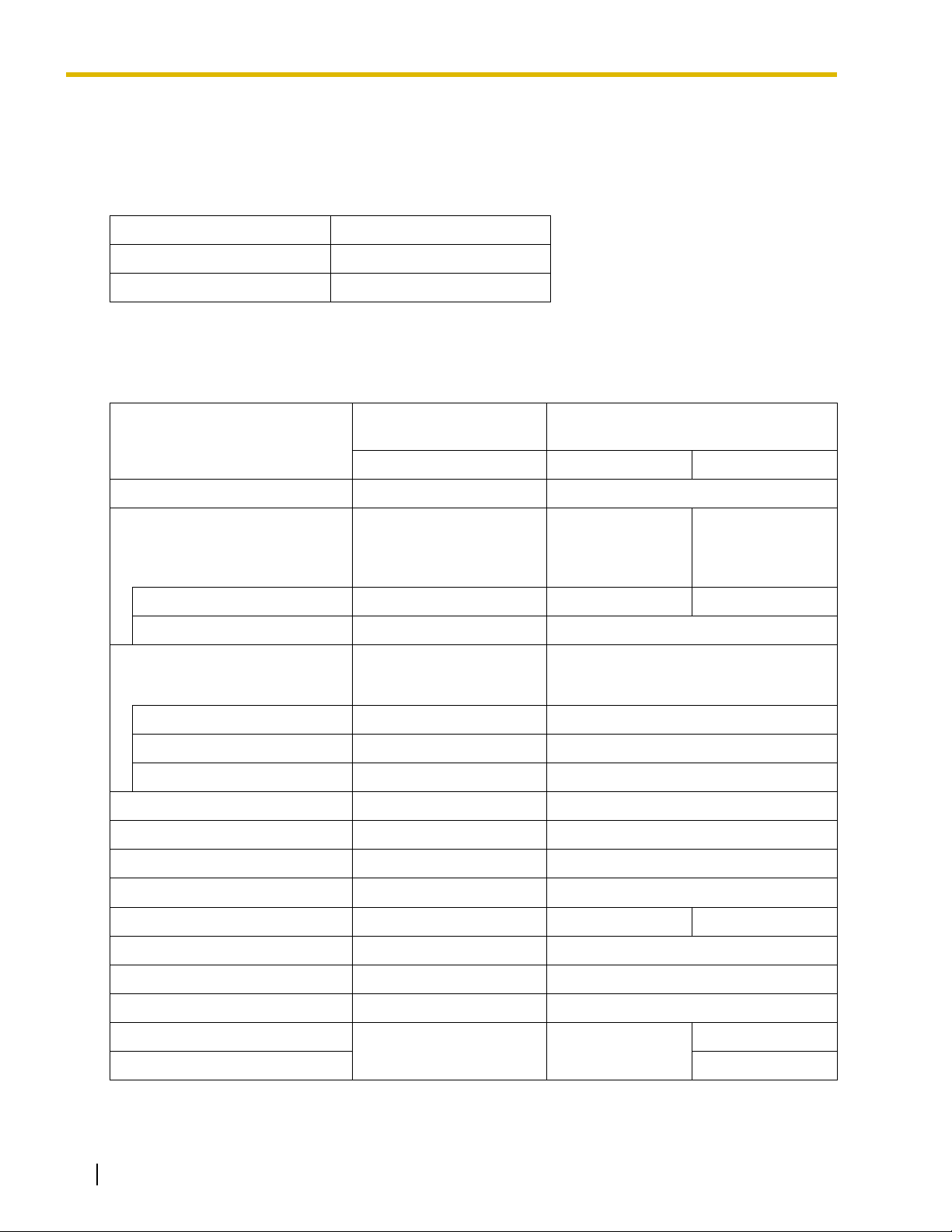
1.4.3 System Capacity
Maximum CO Line and VoIP Line
The Hybrid IP-PBX supports the following number of CO lines and VoIP lines.
Line Type Maximum Number
CO Line 12
VoIP Line 4
Maximum Terminal Equipment
The following number of items of terminal equipment can be supported by the Hybrid IP-PBX. For how to
count the total number of items of equipment to be connected, refer to "MEC Card Calculation".
Terminal Equipment Type Without Additional AC
With Additional AC Adaptor
Adaptor
Without MEC Card Without MEC Card With MEC Card
SLT 24 24
KX-T7600 series DPT/DSS
console
Tot al 24 To t a l 2 4 Tot a l 48
KX-T7600 series DPT 24 24 48
KX-T7600 series DSS console 4 4
Other DPT/DSS console and APT Total 4 Total 24
Other DPT 4 24
Other DSS console 4 4
APT 4 24
DSS console 4 4
CS 4 8
PS 28 28
VPS
4 ports (1 VPS)
*1
4 ports (1 VPS)*
1
SLT, PT, DSS console, and VPS Total 28 Total 28 Total 52
Doorphone 4 4
Door Opener/External Relay 4 4
External Sensor 4 4
Add-on Key Module
USB Module 24
*1
A maximum of 4 ports (8 channels) of a single VPS can be connected to the Hybrid IP-PBX.
26 Installation Manual
Tot al 24 To t a l 2 4
48
Page 27

1.4 Specifications
Note
Devices connected to the Hybrid IP-PBX that exceed the system capacity will not function.
MEC Card Calculation
Calculate the MEC figure from the type and total number of items of equipment to be connected. If the MEC
figure exceeds 28, you need to install an MEC card. Note that you also need to connect an additional AC
adaptor in this case.
MEC Card Calculation
Equipment Type MEC Figure
PT KX-T7600 series DPT/DSS console 1
Other DPT/DSS console 1
APT 1
Pre-installed 4 Super Hybrid Ports 4
Extension Card
*1
SLC4 4
SLC8 8
HLC4 0
PLC4 0
PLC8 0
CS (1 unit) 0
VPS (1 port) 1
*1
Only the extension cards that can support SLTs count for the MEC figures.
Calculation Example
Equipment Type MEC Figure
Pre-installed Super Hybrid Ports 4 ports 4
KX-T7600 series DPT 16 units 16
SLC4 2 cards 8
VPS 4 ports 4
To ta l 32
The total MEC figure is 32. As this exceeds 28, you need to install an MEC card for this configuration.
AC Adaptor Selection
You must connect an additional AC adaptor in any of the following conditions:
• A total of more than 4 APTs, DPTs (except KX-T7600 series), and DSS consoles (except KX-T7600
series) are connected.
• More than 4 CSs are connected.
• An MEC card is required to support a configuration with a total MEC figure exceeding 28.
Installation Manual 27
Page 28

1.4 Specifications
Note
For how to connect an AC adaptor or additional AC adaptor, refer to "2.11.1 Starting the Hybrid IPPBX".
28 Installation Manual
Page 29

Section 2
Installation
This section describes the procedures to install the Hybrid IPPBX. Detailed instructions for planning the installation site,
installing the optional service cards, and cabling of peripheral
equipment are provided. Further information on system
expansion and peripheral equipment installation is included.
Installation Manual 29
Page 30

2.1 Before Installation
2.1 Before Installation
2.1.1 Before Installation
Please read the following notes concerning installation and connection before installing the Hybrid IP-PBX
and terminal equipment.
Be sure to comply with all applicable laws, regulations, and guidelines.
Safety Installation Instructions
When installing telephone wiring, basic safety precautions should always be followed to reduce the risk of
fire, electric shock and injury to persons, including the following:
1. Never install telephone wiring during a lightning storm.
2. Never install telephone jacks in wet locations unless the jack is specifically designed for wet locations.
3. Never touch uninsulated telephone wires or terminals unless the telephone line has been disconnected
at the network interface.
4. Use caution when installing or modifying telephone lines.
Installation Precautions
This Hybrid IP-PBX is designed for wall mounting only, and should be installed in a location where it is
accessible for inspections and maintenance.
To prevent malfunction, noise, or discoloration, avoid installing the system in the following locations:
1. In direct sunlight and hot, cold, or humid places. (Temperature range: 0 °C to 40 °C [32 °F to 104 °F])
2. Areas where sulfuric gases may be present, such as near thermal springs.
3. Areas where shocks or vibrations are frequent or strong.
4. High-dust areas, or places the system may come into contact with water or oil.
5. Near devices that generate high frequencies, such as sewing machines or electric welders.
6. On or near computers, telexes, or other office equipment, as well as microwave ovens or air
conditioners. (It is preferable not to install the system in the same room as the above equipment.)
7. Within 1.8 m (6 ft) of radios and televisions. (Both the Hybrid IP-PBX and PTs should be at least 1.8 m
[6 ft] away from such devices.)
8. Locations where other objects will obstruct the area around the Hybrid IP-PBX. Be especially careful
to leave at least 20 cm (8 in) of space above and 10 cm (4 in) to the sides of the Hybrid IP-PBX for
ventilation.
9. Do not stack up the optional service cards. To avoid damage to the optional service cards, always use
the extension bolts.
Wiring Precautions
Be sure to follow these instructions when wiring the unit:
1. Do not run unshielded telephone cables near AC power cables, computer cables, AC power sources,
etc. When running cables near other noise-generating devices or cables, use shielded telephone
cables or shield the telephone cables with metal tubing.
2. If cables are run on the floor, use protectors to prevent the cables from being stepped on. Avoid running
cables under carpets.
3. Avoid using the same AC outlet for computers, telexes, and other office equipment, as noise generated
by such equipment may hamper system performance or interrupt the system.
30 Installation Manual
Page 31

2.1 Before Installation
4. Use 2-pair telephone cables when connecting PTs.
Use 1-pair telephone cables when connecting SLTs, data terminals, answering machines, computers,
Voice Processing Systems, etc.
5. Unplug the system from its power source when wiring, and plug the system back in only after all wiring
is completed.
6. Mis-wiring may cause the Hybrid IP-PBX to operate improperly. Refer to Section 2 "Installation" when
wiring the system.
7. If an extension does not operate properly, disconnect the telephone from the extension line and connect
it again, or turn off the Hybrid IP-PBX using power switch then turn it on again.
8. For safety purposes this unit is equipped with a grounded plug. If you do not have a grounded outlet,
please have one installed. Do not bypass this safety feature by tampering with the plug.
9. Use twisted pair cable for CO line connection.
10. CO lines should be installed with surge protectors. For details, refer to "2.2.10 Surge Protector
Installation".
11. To assure good quality telephone connection, it is recommended new and modifications to existing
installation of customer premise wiring shall use solid twisted pair copper conductors with minimum 24
gauge that comply with the electrical specifications for Category 3 wiring as detailed in ANSI/EIA/TIA570A Building Wiring Standards.
Installation Manual 31
Page 32

2.2 Installation of the Hybrid IP-PBX
2.2 Installation of the Hybrid IP-PBX
2.2.1 Unpacking
Unpack the box and check the items below:
Main Unit 1
AC Cord 1
AC Adaptor 1
Screws for Wall Mounting 5
Washers for Wall Mounting 5
Mini Plug (for pager and music source) 2
SD Memory Card 1
Main Strap 1
Strap (for the pre-installed LCOT4 card) 1
Optional Card Label Sheet 1
32 Installation Manual
Page 33

2.2.2 Names and Locations
Ground Terminal
DC IN 2
DC IN 1
Power Switch
2.2 Installation of the Hybrid IP-PBX
SD Memory
Card Slot Cover
Reset Button
System Initialize
Switch
MOH port
Pager port
Super Hybrid
Por ts
RS-232C port
USB port
Installation Manual 33
Page 34

2.2 Installation of the Hybrid IP-PBX
2.2.3 Opening/Closing the Covers
Opening the Covers
1. Pull the slide button to the right and, holding it, slide the cable cover upwards. Then turn the cable cover
slightly to remove it.
1
Slide Button
Cable Cover
2. Remove the three screws.
Screw
3. Holding the protrusions on both sides of the front cover, swing the cover open.
34 Installation Manual
Page 35

Removing/Attaching the Front Cover
If you prefer, you can remove the front cover.
Removing the Front Cover
Holding the front cover open at about a 45° angle, remove the front cover by pushing it in the direction
of the arrow as shown below.
2.2 Installation of the Hybrid IP-PBX
Attaching the Front Cover
Fit the front cover to the main unit as shown below, and then close the front cover.
Installation Manual 35
Page 36

2.2 Installation of the Hybrid IP-PBX
Closing the Covers
1. Close the front cover, then tighten the three screws.
Screw
2. Attach the rear hooks on the cable cover to the main unit, then swing the cable cover closed so that the
front hooks fit in place.
Cable Cover
3. Slide the cable cover down until it locks.
36 Installation Manual
Page 37

2.2.4 Installation of the SD Memory Card
LED
2.2 Installation of the Hybrid IP-PBX
SD Memory Card
Slot Cover
SD Memory
Card
CAUTION
• Use only the SD Memory Card included with the Hybrid IP-PBX, or a Panasonic optional upgrade
SD Memory Card.
• The SD Memory Card contains software for all the processes of the Hybrid IP-PBX and all the
customer data. The SD Memory Card must be inserted before start up.
• Do not remove the SD Memory Card while power is supplied to the Hybrid IP-PBX. Doing so may
cause the Hybrid IP-PBX to fail to start when you try to restart the system.
Note
If you need to remove the SD Memory Card:
LED Indications
Indication Color Description
SD ACCESS Green SD memory card status
• ON: Accessing
Installation Manual 37
Page 38

2.2 Installation of the Hybrid IP-PBX
2.2.5 Frame Ground Connection
IMPORTANT
Connect the frame of the Hybrid IP-PBX to ground.
1. Loosen the screw.
Screw
2. Insert a grounding wire (user-supplied)*.
3. Tighten the screw.
4. Connect the grounding wire to ground.
Grounding
wire
To ground
* For grounding wire, green-and-yellow insulation is required, and the cross-sectional area of the
conductor must be more than 0.75 mm
• Be sure to comply with applicable local regulations (e.g., law, guidelines).
• Proper grounding (connection to ground) is very important to protect the Hybrid IP-PBX from the bad
effects of external noise or to reduce the risk to the user of electrocution in the case of a lightning strike.
• The ground wire of the AC cable has an effect against external noise and lightning strikes, but it may
not be enough to protect the Hybrid IP-PBX. A permanent connection between ground and the ground
terminal of the Hybrid IP-PBX must be made.
In most of the continental United States, the ground provided by the "Third wire ground" at the commercial
power outlet will be satisfactory. However, in a small percentage of cases this ground may be installed
incorrectly. Therefore, the following test procedure should be performed.
2
or 18 AWG.
Test Procedure
1. Obtain a suitable voltmeter and set it for a possible reading of up to 250 V AC.
2. Connect the meter probes between the 2 main AC voltage points on the wall outlet. The reading
obtained should be 108 V AC to 132 V AC.
3. Move one of the meter probes to the 3rd prong terminal (GND).
Either the same reading or a reading of 0 volt should be obtained.
4. If a reading of 0 volt at one terminal and a reading of 108 V AC to 132 V AC at the other terminal
is not obtained, the outlet is not properly grounded.
This condition should be corrected by a qualified electrician (per article 250 of the National
Electrical Code).
5. If a reading of 0 volt at one terminal and a reading of 108 V AC to 132 V AC at the other terminal
is obtained, then set the meter to the "OHMS/RX1" scale, place one probe at the GND Terminal
and the other probe at the terminal which gave a reading of 0 volt.
A reading of less than 1 ohm should be obtained. If the reading is not obtained, the outlet is not
adequately grounded. See qualified electrician.
38 Installation Manual
Page 39

2.2 Installation of the Hybrid IP-PBX
2.2.6 Installing/Removing the Optional Service Cards
Slot Position
1
11*
10
1
*
04
07
09
08
1
Slots 10 and 11 accept only cards that do not have external ports. Therefore, these slots do not have
*
03
02*
01*
2
3
06
05
removable cover plates.
2
Slot 02 has an LCOT4 card pre-installed.
*
3
Slot 01 contains the pre-installed Super Hybrid Ports. No optional service card can be installed.
*
Slot Restrictions
The following table shows the slot restrictions. " " indicates that the slot supports the optional service card.
Card Slot Number
Type Max 02030405060708091011
LCOT4
HLC4
DLC4
SLC4
*1
3
*2
1
PLC4
IP-GW4 1
DLC8
SLC8
*3
2
PLC8
DPH4 1
ECHO8 1
EXT-CID 1
MSG2 2
*1
Including one LCOT4 card that is installed by default.
*2
Only one of HLC, DLC4 , SLC4 or PLC4 card can be installed.
Installation Manual 39
Page 40

2.2 Installation of the Hybrid IP-PBX
*3
A maximum of two DLC8, SLC8 and PLC8 cards can be installed.
CAUTION
To protect the main board from static electricity, do not touch parts on the main board or on the optional
service cards. To discharge static electricity, touch ground or wear a grounding strap.
Notes
• When installing or removing the optional service cards, the power switch of the Hybrid IP-PBX must
be in the off position.
• For each card, the maximum number that can be installed in the Hybrid IP-PBX is listed in "1.3.1
Options".
• Any card that exceeds the capacity of the Hybrid IP-PBX will be ignored.
• When the Hybrid IP-PBX starts up with an invalid configuration, some cards will be ignored.
Installing Optional Service Cards
1. Before installing the optional service cards, cut and remove the appropriate dummy cover plates from
the main unit.
Dummy Cover Plate
CAUTION
For safety reasons, smooth the cut edges after removing the dummy cover plates.
40 Installation Manual
Page 41

2.2 Installation of the Hybrid IP-PBX
2. Position the card in the open slot, making sure that the tabs on the both sides of the card fit into place.
Then, holding the card firmly in place, lower the rear end so that the hole of the card fits over the
extension bolt.
Optional Service Card
1
2
Extension Bolt
CAUTION
When installing the optional service cards, do not put pressure on any parts of the main board (e.g., tall
capacitors). Doing so may result in damage to the Hybrid IP-PBX.
3. Insert the new extension bolt (included with the card) into the hole on the card, and tighten it to secure
the card.
Extension Bolt
Installation Manual 41
Page 42

2.2 Installation of the Hybrid IP-PBX
4. Stick an appropriate optional card label (included) to the left side of the corresponding card.
Optional Card Label
5. Connect a cable to an appropriate port of the card.
For details about pin assignments, refer to the appropriate section in "2.3 Installation of the CO Line
Cards" and "2.4 Installation of the Extension Cards".
Note
Make sure to connect cables after installing the card in the Hybrid IP-PBX, not before.
42 Installation Manual
Page 43

2.2 Installation of the Hybrid IP-PBX
6. Repeat the procedure for other cards.
A. When installing a card in Slot 07, make sure to detach the LED holder first. After installing the card,
reattach the LED holder.
To detach the LED holder
LED holder
To attach the LED holder
Installation Manual 43
Page 44

2.2 Installation of the Hybrid IP-PBX
B. When installing a card in Slot 11, tighten the card using the screw included with the card, instead
of the extension bolt.
Screw
44 Installation Manual
Page 45

Handling of the Cables
Attach the strap included with the card to one of the connected cables.
1.
Strap
2.2 Installation of the Hybrid IP-PBX
2. Bind all the connected cables together using the strap.
3. Repeat the procedure for other cards.
Installation Manual 45
Page 46

2.2 Installation of the Hybrid IP-PBX
4. Attach the main strap (included with the Hybrid IP-PBX) to any of the 5 rails depending on your
preference.
1
Main Strap
2
46 Installation Manual
Page 47

2.2 Installation of the Hybrid IP-PBX
5. Bind all the connected cables together using the main strap, and then close the cable cover. For
how to close the cable cover, refer to "2.2.3 Opening/Closing the Covers".
Cable Cover
Main Strap
Notes
• For safety reasons, do not stretch, bend, or pinch the cables.
• If you prefer, you can cut the other side of the cable cover and run the cables through that
opening. For safety reasons, smooth the cut edges.
Installation Manual 47
Page 48

2.2 Installation of the Hybrid IP-PBX
Removing the Optional Service Cards
1. Loosen the extension bolt.
2. Holding the protrusions of the card, pull the card in the direction of the arrows.
CAUTION
When removing the optional service cards, do not put pressure on any parts of the main board (e.g.,
tall capacitors). Doing so may result in damage to the Hybrid IP-PBX.
48 Installation Manual
Page 49

2.2.7 Types of Connectors
Connector Type Pin Number Used for
2.2 Installation of the Hybrid IP-PBX
(Twisted pair cable)
(Twisted pair cable)
10-pin
Terminal Block
RJ11
RJ45
8-pin
Terminal Block
4 1
1 8
• DPH4 (KX-TDA5161)
• HLC4 (KX-TDA5170)
• DLC4 (KX-TDA5171)
• DLC8 (KX-TDA5172)
• SLC4 (KX-TDA5173)
• SLC8 (KX-TDA5174)
• PLC4 (KX-TDA5175)
• PLC8 (KX-TDA5176)
• LCOT4 (KX-TDA5180)
• Super Hybrid Ports (Main Board)
• IP-GW4 (KX-TDA5480)
• DPH4 (KX-TDA5161)
81
RS-232C
USB
Mini Plug
1 5
6 9
2
3
1
4
+
-
101
• Main Board
• Main Board
• Main Board (Pager port, MOH port)
Installation Manual 49
Page 50

2.2 Installation of the Hybrid IP-PBX
2.2.8 Wall Mounting (KX-TDA50)
Mounting on Wooden Wall
1. Place the reference for wall mounting (on the last page of this manual) on the wall to mark the three
screw positions.
130 mm (5-1/8 in)
250 mm
(9-13/16 in)
2. Install the screws and washers (included) in the wall.
Washer
Drive the screw
to this position.
Notes
• Make sure that the screw heads are at the same distance from the wall.
• Install the screws perpendicular to the wall.
3. Hook the main unit on the screw heads.
Notes
• Do not block the openings of the cabinet. Leave at least 20 cm (8 in) of space above and 10 cm (4
in) to the sides of the Hybrid IP-PBX for ventilation.
• Make sure that the wall behind the cabinet is flat and free of obstacles, so that the openings on the
back of the cabinet will not be blocked.
• Be careful not to drop the cabinet.
50 Installation Manual
Page 51

2.2 Installation of the Hybrid IP-PBX
Mounting on Concrete or Mortar Wall
CAUTION
Drive mounting screws into the wall. Be careful to avoid touching any metal laths, wire laths or metal
plates in the wall.
1. Place the reference for wall mounting (on the last page of this manual) on the wall to mark the three
screw positions.
130 mm (5-1/8 in)
250 mm
(9-13/16 in)
2. Install three anchor plugs (user-supplied) in the wall.
Hammer
Anchor Plug
6.4 mm
(1/4 in)
29 mm
(1-1/8 in)
3. Install the screws (included) in the wall.
Drive the screw
to this position.
4. Hook the main unit on the screw heads.
Installation Manual 51
Page 52

2.2 Installation of the Hybrid IP-PBX
Notes
• Do not block the openings of the cabinet. Leave at least 20 cm (8 in) of space above and 10 cm (4
in) to the sides of the Hybrid IP-PBX for ventilation.
• Make sure that the wall behind the cabinet is flat and free of obstacles, so that the openings on the
back of the cabinet will not be blocked.
• Be careful not to drop the cabinet.
52 Installation Manual
Page 53

2.2 Installation of the Hybrid IP-PBX
2.2.9 Wall Mounting (AC Adaptor)
Mounting on Wooden Wall
1. Place the reference for wall mounting (on the following page) on the wall to mark the two screw
positions.
110 mm
(4-5/16 in)
2. Install the screws and washers (included) in the wall.
Washer
Drive the screw
to this position.
Notes
• Make sure that the screw heads are at the same distance from the wall.
• Install the screws perpendicular to the wall.
3. Hook the AC adaptor on the screw heads.
Note
Be careful not to drop the AC adaptor.
Installation Manual 53
Page 54

2.2 Installation of the Hybrid IP-PBX
Mounting on Concrete or Mortar Wall
CAUTION
Drive mounting screws into the wall. Be careful to avoid touching any metal laths, wire laths or metal
plates in the wall.
1. Place the reference for wall mounting (on the following page) on the wall to mark the two screw
positions.
110 mm
(4-5/16 in)
2. Install two anchor plugs (user-supplied) in the wall.
Hammer
Anchor Plug
6.4 mm
(1/4 in)
29 mm
(1-1/8 in)
3. Install the screws (included) in the wall.
Drive the screw
to this position.
4. Hook the AC adaptor on the screw heads.
Note
Be careful not to drop the AC adaptor.
54 Installation Manual
Page 55

Reference for Wall Mounting
Please copy this page and use as a reference for wall mounting.
Install a screw here.
110 mm
(4-5/16 in)
2.2 Installation of the Hybrid IP-PBX
Install a screw here.
Note
Make sure to set the print size to correspond with the size of this page. If the dimension of the paper
output still deviates slightly from the measurement indicated here, use the measurement indicated
here.
Installation Manual 55
Page 56

2.2 Installation of the Hybrid IP-PBX
2.2.10 Surge Protector Installation
Overview
A massive electrical surge can be caused if lightning strikes a telephone cable 10 m (33 ft) above ground,
or if a telephone line comes into contact with a power line. A surge protector is a device that is connected
to a CO line to prevent potentially dangerous electrical surges from entering the building via the CO line and
damaging the Hybrid IP-PBX and connected equipment.
To protect the system from electrical surges, we strongly recommend connecting the system to a surge
protector that meets the following specifications:
• Surge arrestor type: 3-electrode arrestor
• DC spark-over voltage: 230 V
• Maximum peak current: at least 10 kA
Additionally, proper grounding is very important for the protection of the system (refer to "2.2.5 Frame
Ground Connection").
Many countries/areas have regulations requiring surge protection. Be sure to comply with all applicable
laws, regulations, and guidelines.
Installation
CO Line CO Line CO Line
Surge
Protector
Terminal
Board
Extn. Extn. Extn.
SLT PT
Ground
Extn.
CS
Hybrid
IP-PBX
Frame
Ground
Extn.: Extension line
56 Installation Manual
Page 57

Outside Installation
(Main Building)
2.2 Installation of the Hybrid IP-PBX
CO Line
If you install an extension outside of the building, the following precautions are recommended:
Surge Protector
CO Line
Terminal
Board
Extn. Extn.
Extn.
CSSLT PT
Hybrid
IP-PBX
Extn.
Surge
Protector
Ground
(Another Building)
SLT
PT
CS
Extn.: Extension Line
a. Install the extension wire underground.
b. Use a conduit to protect the wire.
Note
The surge protector for an extension and CS is different from that for a CO line.
Installation of a Ground Rod
Surge Protector
CO Line
Grounding
Wire
(Underground)
Ground Rod
Hybrid
IP-PBX
Installation Manual 57
Page 58

2.2 Installation of the Hybrid IP-PBX
1. Connect the ground rod to the surge protector using a grounding wire with a cross-sectional area of at
2
least 1.3 mm
.
2. Bury the ground rod near the protector. The grounding wire should be as short as possible.
3. The grounding wire should run straight to the ground rod. Do not run the wire around other objects.
4. Bury the ground rod at least 50 cm (20 in) underground.
Notes
• The above figures are recommendations only.
• The length of ground rod and the required depth depend on the composition of the soil.
58 Installation Manual
Page 59

2.3 Installation of the CO Line Cards
2.3 Installation of the CO Line Cards
2.3.1 LCOT4 Card
Function
4-port analog CO line card with 2 power failure transfer (PFT) ports. One CID4 card can be mounted on the
LCOT4 card (refer to "2.3.2 CID4 Card").
PFT Port 2
PFT Port 1
RJ11
To CO line
Accessories and User-supplied Items
Accessories (included): Extension Bolt × 1, Strap × 1
User-supplied (not included): RJ11 connector
Notes
• To confirm the CO line connection, refer to "Confirming the CO Line Connection" in "2.11.1 Starting
the Hybrid IP-PBX".
• For details about power failure transfer, refer to "2.10.1 Power Failure Connections".
Pin Assignments
RJ11 Connector
Signal Name Function
T R
4 1
RRing
TTip
– Reserved
Installation Manual 59
Page 60

2.3 Installation of the CO Line Cards
2.3.2 CID4 Card
Function
4-port Caller ID signal type FSK/FSK (with Call Waiting Caller ID [Visual Caller ID])/DTMF. To be mounted
on the LCOT4 card.
CID4 Card
LCOT4 Card
Accessories and User-supplied Items
Accessories (included): none
User-supplied (not included): none
Note
If you need to remove the CID4 card:
60 Installation Manual
Page 61

2.3 Installation of the CO Line Cards
2.3.3 IP-GW4 Card
Function
4-channel VoIP gateway card. Compliant with VoIP H.323 V.2 protocol, and ITU-T G.729a, G.723.1, and
G.711 CODEC methods.
RJ45
LEDs
To private IP network
Accessories and User-supplied Items
Accessories (included): Extension Bolt × 1, Strap × 1
User-supplied (not included): RJ45 connector
Notes
• Maximum length of the cable to be connected to this optional service card is 100 m (328 ft).
• For programming instructions and other information about the IP-GW4 card, refer to the
documentation for the IP-GW4 card.
• To confirm the CO line connection, refer to "Confirming the CO Line Connection" in "2.11.1 Starting
the Hybrid IP-PBX".
Pin Assignments
RJ45 Connector (10BASE-T/100BASE-TX)
Signal Name Input (I)/Output (O) Function
TPO+
TPO-
TPI+
TPI-
1 8
TPO+ O Transmit data+
TPO- O Transmit data-
TPI+ I Receive data+
TPI- I Receive data-
–– Reserved
Installation Manual 61
Page 62

2.3 Installation of the CO Line Cards
LED Indications
Indication Color Description
ON LINE Green On-line status indication
ALARM Red Alarm indication
LINK Green Link status indication
DATA Green Data transmission indication
• ON: On-line mode
• OFF: Off-line mode
• Flashing: Maintenance mode
Note
If the LINK indicator is OFF, the ON LINE indicator will also be
OFF.
• ON: Alarm
• OFF: Normal
• ON: Normal Connection
• OFF: Connection Error
• ON: Data transmitting
• OFF: No data transmitted
62 Installation Manual
Page 63

2.4 Installation of the Extension Cards
2.4 Installation of the Extension Cards
2.4.1 HLC4 Card
Function
4-port extension card for SLTs, APTs, DSS consoles, a Voice Processing System (VPS), and PT-interface
*1
CSs.
RJ11
To extension
Accessories and User-supplied Items
Accessories (included): Extension Bolt × 1, Strap × 1
User-supplied (not included): RJ11 connector
Note
For details about connecting the CS, refer to "2.7.7 Connecting a Cell Station to the Hybrid IP-PBX".
Pin Assignments
RJ11 Connector
Signal Name Function
D2 D1
R T
4 1
D1 Data port (High)
TTip
RRing
D2 Data port (Low)
*1
The PT-interface CS can be connected to the Hybrid IP-PBX using a cable like a PT.
Installation Manual 63
Page 64

2.4 Installation of the Extension Cards
2.4.2 DLC4 Card
Function
4-port digital extension card for DPTs, DSS consoles, a VPS, and PT-interface CSs.
RJ11
To extension
Accessories and User-supplied Items
Accessories (included): Extension Bolt × 1, Strap × 1
User-supplied (not included): RJ11 connector
*1
Note
For details about connecting the CS, refer to "2.7.7 Connecting a Cell Station to the Hybrid IP-PBX".
Pin Assignments
RJ11 Connector
D2 D1
4 1
Signal Name Function
D1 Data port (High)
D2 Data port (Low)
– Reserved
*1
The PT-interface CS can be connected to the Hybrid IP-PBX using a cable like a PT.
64 Installation Manual
Page 65

2.4.3 SLC4 Card
Function
4-port extension card for SLTs.
RJ11
To extension
Accessories and User-supplied Items
Accessories (included): Extension Bolt × 1, Strap × 1
User-supplied (not included): RJ11 connector
2.4 Installation of the Extension Cards
Pin Assignments
RJ11 Connector
R T
4 1
Signal Name Function
TTip
RRing
– Reserved
Installation Manual 65
Page 66

2.4 Installation of the Extension Cards
2.4.4 PLC4 Card
Function
4-port extension card for APTs, DSS consoles, and a VPS.
RJ11
To extension
Accessories and User-supplied Items
Accessories (included): Extension Bolt × 1, Strap × 1
User-supplied (not included): RJ11 connector
Pin Assignments
RJ11 Connector
D2 D1
R T
4 1
Signal Name Function
D1 Data port (High)
TTip
RRing
D2 Data port (Low)
66 Installation Manual
Page 67

2.4 Installation of the Extension Cards
2.4.5 DLC8 Card
Function
8-port digital extension card for DPTs, DSS consoles, a VPS, and PT-interface CSs.
RJ11
*1
To extensions
Accessories and User-supplied Items
Accessories (included): Extension Bolt × 1, Strap × 1
User-supplied (not included): RJ11 connector
Note
For details about connecting the CS, refer to "2.7.7 Connecting a Cell Station to the Hybrid IP-PBX".
Pin Assignments
RJ11 Connector
Signal Name Function
D2 D1
4 1
D1 Data port (High)
D2 Data port (Low)
– Reserved
*1
The PT-interface CS can be connected to the Hybrid IP-PBX using a cable like a PT.
Installation Manual 67
Page 68

2.4 Installation of the Extension Cards
2.4.6 SLC8 Card
Function
8-port extension card for SLTs.
RJ11
To extensions
Accessories and User-supplied Items
Accessories (included): Extension Bolt × 1, Strap × 1
User-supplied (not included): RJ11 connector
Pin Assignments
RJ11 Connector
Signal Name Function
R T
4 1
TTip
RRing
– Reserved
68 Installation Manual
Page 69

2.4.7 PLC8 Card
Function
8-port extension card for APTs, DSS consoles, and a VPS.
RJ11
2.4 Installation of the Extension Cards
To extensions
Accessories and User-supplied Items
Accessories (included): Extension Bolt × 1, Strap × 1
User-supplied (not included): RJ11 connector
Pin Assignments
RJ11 Connector
Signal Name Function
D2 D1
R T
4 1
D1 Data port (High)
TTip
RRing
D2 Data port (Low)
Installation Manual 69
Page 70

2.5 Installation of the Other Cards
2.5 Installation of the Other Cards
2.5.1 DPH4 Card
Function
4-port doorphone card for 4 doorphones, 4 door openers or external relays, and 4 external sensors.
10-pin
8-pin
RJ11
To external sensors
Telephone Line Cord
To door openers/
external relays
To doorphones
Accessories and User-supplied Items
Accessories (included): Extension Bolt × 1, Strap × 1, 8-pin terminal block × 1, 10-pin terminal block ×
1, Telephone Line Cord × 2, Terminal Box × 2
User-supplied (not included): Copper wire
Note
For details about connection to doorphones, door openers, external sensors, and external relays, refer
to "2.8.1 Connection of Doorphones, Door Openers, External Sensors, and External Relays".
Pin Assignments
RJ11 Connector
Signal Name Function
DP2 Doorphone 2 transmit
5 81 4
DP1 Doorphone 1 transmit
DP2
DP1
com1
com2
70 Installation Manual
DP4
DP3
com3
com4
com1 Doorphone 1 receive
com2 Doorphone 2 receive
DP4 Doorphone 4 transmit
DP3 Doorphone 3 transmit
com3 Doorphone 3 receive
com4 Doorphone 4 receive
Page 71

8-pin Terminal Block
2.5 Installation of the Other Cards
Signal Name Function
SENS 1a
SENS 1b
SENS 2a
SENS 2b
SENS 3a
SENS 3b
SENS 4a
SENS 4b
1
10-pin Terminal Block
OP1b (RL1b)
OP1a (RL1a)
OP2b (RL2b)
OP2a (RL2a)
OP3b (RL3b)
OP3a (RL3a)
OP4b (RL4b)
OP4a (RL4a)
1
SENS 1a Sensor Input 1
SENS 1b com 1
SENS 2a Sensor Input 2
SENS 2b com 2
SENS 3a Sensor Input 3
8
SENS 3b com 3
SENS 4a Sensor Input 4
SENS 4b com 4
Signal Name Function
OP1b (RL1b) Door opener 1 (Relay 1)
OP1a (RL1a) Door opener 1 com (Relay 1 com)
OP2b (RL2b) Door opener 2 (Relay 2)
OP2a (RL2a) Door opener 2 com (Relay 2 com)
OP3b (RL3b) Door opener 3 (Relay 3)
10
OP3a (RL3a) Door opener 3 com (Relay 3 com)
OP4b (RL4b) Door opener 4 (Relay 4)
OP4a (RL4a) Door opener 4 com (Relay 4 com)
– Reserved
Installation Manual 71
Page 72

2.5 Installation of the Other Cards
Connection Diagram for External Sensors and External Relays
Power to the external sensor is provided from the DPH4 card and must be grounded through the DPH4 card
as indicated in the diagram below. A pair of "sensor" and "common" lines must be connected to the DPH4
card for each external sensor. The Hybrid IP-PBX detects input from the sensor when the signal is under
100 Ω.
Sensor 4
Sensor 3
Sensor 2
Sensor 1
sensor
common
sensor
common
sensor
common
sensor
common
10
9
8
7
6
5
4
3
2
1
2.2K
47K
5 V
10K Ω
5 V
33 Ω
33 Ω
2.2K
47K
5 V
10K Ω
5 V
33 Ω
33 Ω
2.2K
47K
5 V
10K Ω
5 V
33 Ω
33 Ω
5 V
10K Ω
2.2K
47K
5 V
33 Ω
8
33 Ω
7
6
5
4
3
2
1
Relay 4
Relay 3
Relay 2
Relay 1
72 Installation Manual
Page 73

2.5.2 ECHO8 Card
Function
8-channel card for echo cancellation during conferences.
Accessories and User-supplied Items
Accessories (included): Extension Bolt × 1, Screw × 1
User-supplied (not included): none
Note
To establish a conference call involving 6 to 8 parties, install an ECHO8 card and enable the echo
cancellation for conference using the KX-TDA50 Maintenance Console. For details, refer to the on-line
help of the KX-TDA50 Maintenance Console.
2.5 Installation of the Other Cards
Installation Manual 73
Page 74

2.5 Installation of the Other Cards
2.5.3 MSG2 Card
Function
2-channel message card.
Accessories and User-supplied Items
Accessories (included): Extension Bolt × 1, Screw × 1
User-supplied (not included): none
74 Installation Manual
Page 75

2.5.4 EXT-CID Card
Function
Sends Caller ID signals to extension ports.
Accessories and User-supplied Items
Accessories (included): Extension Bolt × 1, Screw × 1
User-supplied (not included): none
2.5 Installation of the Other Cards
Installation Manual 75
Page 76

2.5 Installation of the Other Cards
2.5.5 MEC Card
Function
Memory expansion card to increase Personal/System Speed Dialing number storage space, double the
number of DPTs (using Digital XDP connection), and display language selection for VM Menu. To be
installed in the MEC slot.
MEC Card
MEC Slot
Accessories and User-supplied Items
Accessories (included): none
User-supplied (not included): none
CAUTION
Make sure to insert the MEC card between the guide rails until it locks into the MEC slot. Push the card
firmly into place until you hear a clicking sound.
76 Installation Manual
Page 77

2.5 Installation of the Other Cards
Removing the MEC Card
Pull open the guide rails using a flathead screwdriver and, while holding them open, remove the MEC card.
Installation Manual 77
Page 78

2.5 Installation of the Other Cards
2.5.6 RMT Card
Function
Analog modem card for remote communication with the Hybrid IP-PBX. ITU-T V.90 support.
RMT Card
RMT Slot
Accessories and User-supplied Items
Accessories (included): none
User-supplied (not included): none
CAUTION
Make sure to insert the RMT card between the guide rails until it locks into the RMT slot. Push the card
firmly into place until you hear a clicking sound.
78 Installation Manual
Page 79

2.5 Installation of the Other Cards
Removing the RMT Card
Pull open the guide rails using a flathead screwdriver and, while holding them open, remove the RMT card.
Installation Manual 79
Page 80

2.6 Connection of Extensions
2.6 Connection of Extensions
2.6.1 Maximum Cabling Distances of the Extension Wiring (Twisted Cable)
Cable Maximum Distance
26 AWG: 222 m (728 ft)
24 AWG: 347 m (1138 ft)
22 AWG: 500 m (1640 ft)
CAT 5: 347 m (1138 ft)
Cable Maximum Distance
26 AWG: 500 m (1640 ft)
24 AWG: 720 m (2362 ft)
22 AWG: 830 m (2723 ft)
CAT 5: 720 m (2362 ft)
Cable Maximum Distance
26 AWG: 380 m (1246 ft)
24 AWG: 550 m (1804 ft)
22 AWG: 630 m (2066 ft)
CAT 5: 550 m (1804 ft)
Cable Maximum Distance
26 AWG: 140 m (459 ft)
24 AWG: 229 m (751 ft)
22 AWG: 360 m (1181 ft)
CAT 5: 229 m (751 ft)
PT-interface CS
KX-T7600 Series
KX-T7600 Series
(Master DPT on the
Digital XDP connection)
Other PT and
DSS Console
Notice
The maximum cabling distance may vary depending on the conditions.
80 Installation Manual
Cable Maximum Distance
26 AWG: 698 m (2289 ft)
24 AWG: 1128 m (3700 ft)
22 AWG: 1798 m (5897 ft)
CAT 5: 1128 m (3700 ft)
SLT
Page 81

2.6 Connection of Extensions
PT-interface CS DPT APT
KX-T7600 series Other
Super Hybrid Ports
(Main Board)
SLC4, SLC8 Cards
DLC4, DLC8 Cards
PLC4, PLC8 Cards
HLC4 Card
" " indicates that the extension card or Super Hybrid Ports support the terminal.
DSS Console
SLT
Installation Manual 81
Page 82

2.6 Connection of Extensions
2.6.2 Parallel Connection of the Extensions
Any SLT can be connected in parallel with an APT or a DPT as follows.
Note
In addition to an SLT, an answering machine, a fax machine or a modem (PC) can be connected in
parallel with an APT and a DPT.
With APT
To a Super Hybrid Port
Modular
T-Adaptor
2-conductor wiring cord
Connect pins "T" and "R".
4-conductor wiring cord
Connect pins "T", "R", "D1",
and "D2".
SLTAPT
With DPT
Parallel mode or eXtra Device Port (XDP) mode can be selected through system programming.
If XDP mode is enabled through system programming, parallel connection is not possible. Refer to "1.10.9
Paralleled Telephone" and "2.1.1 Extension Port Configuration" in the Feature Guide for further information.
Using a Modular T-Adaptor
To a Super Hybrid Port
Modular
T-Adaptor
2-conductor wiring cord
Connect pins "T" and "R".
4-conductor wiring cord
Connect pins "D1" and
"D2".
82 Installation Manual
SLTDPT
Page 83

Using an EXtra Device Port
With KX-T7600 Series DPT
To a Super Hybrid Port
2.6 Connection of Extensions
4-conductor wiring cord
Connect pins "T", "R",
"D1" and "D2".
2-conductor wiring cord
Connect pins "T" and "R".
DPT SLT
To a Super Hybrid Port
To S LT
With Other DPT (except KX-T7560 and KX-T7565)
To a Super Hybrid Port
2-conductor wiring cord
4-conductor wiring cord
Connect pins "T", "R",
"D1" and "D2".
Connect pins "T" and "R".
TO MAIN UNIT
/ PABX
TO TEL
TO EMSS or TO MAIN UNIT
To a Super Hybrid Port
DPT
SLT
TO TEL
To S LT
Installation Manual 83
Page 84

2.6 Connection of Extensions
2.6.3 Digital EXtra Device Port (Digital XDP) Connection
A DPT can be connected to another DPT on the Digital XDP connection. In addition, if the DPT is connected
to a Super Hybrid Port, it can also have an SLT connected in Parallel mode or XDP mode.
Notes
• Both DPTs must be KX-T7600 series DPTs (excluding KX-T7640).
• Parallel mode or XDP mode can be selected through system programming.
• If XDP mode is enabled through system programming, parallel connection is not possible. Refer to
"1.10.9 Paralleled Telephone" and "2.1.1 Extension Port Configuration" in the Feature Guide for
further information.
With KX-T7600 Series DPT
Using a Modular T-Adaptor
To DLC4/DLC8 card
To a Super Hybrid Port
(for connection of SLT)
4-conductor wiring cord
Connect pins "D1" and
"D2".
Back View of DPTs
TO TEL
Modular
T-Adaptor
4-conductor wiring cord
Connect pins "D1" and "D2".
Master DPT
Cable Maximum Distance
26 AWG: 30 m (98 ft)
24 AWG: 50 m (164 ft)
22 AWG: 60 m (196 ft)
CAT 5: 50 m (164 ft)
2-conductor wiring cord
Connect pins "T" and "R".
SLT
Slave DPT
TO MAIN UNIT
/ PABX
TO MAIN UNIT
/ PABX
84 Installation Manual
Slave DPTMaster DPT
To DLC4/DLC8 card
To a Super Hybrid Port
(for connection of SLT)
Page 85

Using an EXtra Device Port
To DLC4/DLC8 card
2.6 Connection of Extensions
To a Super Hybrid Port
(for connection of SLT)
4-conductor wiring cord
Connect pins "T", "R",
"D1" and "D2".
Back View of DPTs
TO TEL
TO MAIN UNIT
/ PABX
4-conductor wiring cord
Connect pins "T", "R",
"D1" and "D2".
Cable Maximum Distance
26 AWG: 30 m (98 ft)
24 AWG: 50 m (164 ft)
22 AWG: 60 m (196 ft)
CAT 5: 50 m (164 ft)
2-conductor wiring cord
Connect pins "T" and "R".
SLTMaster DPT Slave DPT
TO MAIN UNIT
/ PABX
TO TEL
Slave DPTMaster DPT
To DLC4/DLC8 card
To a Super Hybrid Port
(for connection of SLT)
To S LT
Installation Manual 85
Page 86

2.6 Connection of Extensions
ULL
2.6.4 First Party Call Control CTI Connection
CTI connection between a PC and a KX-T7633/T7636 DPT provides first party call control. The CTI
connection is made via a USB interface (version 1.1), and uses the TAPI 2.1 protocol.
A USB Module (KX-T7601) must be connected to the KX-T7633/T7636 DPT.
Note
The operating system of the PC required for first party call control depends on your CTI application
software. For details, refer to the manual for your CTI application software.
To P C
USB Cable
USB Port
USB Module
Notes
• Maximum length of the USB cable is 3 m (9 ft 10 in).
• USB Modules must not be connected to DPTs in the Digital XDP connection. In a Digital XDP
connection, the PC cannot be used. If a USB module is connected to a slave DPT, the DPT will not
work properly.
86 Installation Manual
Page 87

2.7 Connection of 2.4 GHz Portable Stations
2.7 Connection of 2.4 GHz Portable Stations
2.7.1 Overview
The following equipment is required to connect the wireless system:
CS: Cell Station (KX-T0141)
This unit determines the area covered by the wireless system. Up to 2 calls can be made at the same time
through each CS.
PS: 2.4 GHz Portable Station (KX-TD7680/KX-TD7690)
The KX-TDA50 can support up to 28 PSs. For more details about the PS, refer to the PS Operating
Instructions.
CAUTION
• The CS should be kept free of dust, moisture, high temperature (more than 40 °C [104 °F]), low
temperature (less than 0 °C [32 °F]), vibration, and should not be exposed to direct sunlight.
• The CS should not be placed outdoors (use indoors).
• The CS should not be placed near high voltage equipment.
• The CS should not be placed on a metal object.
• Systems using 2.4 GHz ISM (Industrial, Scientific and Medical) band may interfere with the KX-
TDA wireless system. Examples of such systems are cordless telephones, wireless LAN, Home
RF, microwave ovens and other ISM devices. These systems may cause minor noise.
• Keeping some distance between the equipment listed below may prevent interference. (The
distance may vary depending on the environment.)
Equipment Distance
CS and office equipment such as a computer, telex, fax
machine, etc.
CS and PS More than 1 m (3 ft 3 in)
Each PS More than 0.5 m (1 ft 8 in)
Hybrid IP-PBX and CS More than 2 m (6 ft 7 in)
CS and CS More than 15 m (49 ft)
Please take into consideration the distance between the CSs when site planning. Please consult
a certified dealer for details.
However, the required distance between CSs may vary depending on the environment of the
installation site and conditions in which the wireless system is used. Conduct the site survey to
determine the appropriate distance.
More than 2 m (6 ft 7 in)
Installation Manual 87
Page 88

2.7 Connection of 2.4 GHz Portable Stations
9
2.7.2 Procedure Overview
When connecting the wireless system, use extreme care to conduct a site survey. Inadvertent site survey
can result in poor service area, frequent noise, and disconnection of calls.
1. Investigate the installation site
Refer to "2.7.3 Site Planning".
a. Obtain the map of the CS installation site.
b. Consider the service area demanded by the user on the map.
c. Plan the locations of each CS, taking account of distance, building materials and etc.
2. Prepare the CS for site survey
Refer to "2.7.4 Before Site Survey".
a. Assign a CS number to each CS by setting the DIP switches on the back of the CS.
b. Supply electricity to each CS using an AC adaptor or a battery box.
c. Install each CS temporarily as planned.
Notes
• Install at least 2 m (6 ft 7 in) above the floor.
• Keep the antennas in the upright position.
3. Conduct the site survey
Refer to "2.7.5 Site Survey".
a. Test the radio signal strength using the PS.
Confirm that the radio signal strength level is "12" near the CS.
Using the KX-TD7680
9
1
Press 1, 9, and POWER
for more than 2 seconds.
Using the KX-TD7690
9
1
Press 1, 9, and POWER
for more than 2 seconds.
b. By walking away from the CS with the PS, check the radio signal strength. The radio signal strength
weakens as you walk away from the CS.
c. Map the CS coverage area at radio signal strength levels "3" and "8".
d. Make sure that adjacent CS coverage areas overlap where the radio signal strength level is "8" by
at least 5 m (16 ft).
e. Make sure that the radio signal strength level is greater than "3" at any location within the service
area demanded by the user.
0
0
CS No.
1 to 9
CS No.
1 to 9
Display example:
<< SEARCHING >>
Display example:
<< SEARCHING >>
CS NO.1 LEVEL:12
SAVE:0123456789
CS NO.1 LEVEL:12
SAVE:0123456789
88 Installation Manual
Page 89

2.7 Connection of 2.4 GHz Portable Stations
4. Finish the site survey
Refer to "2.7.6 After Site Survey".
a. Return all DIP switches of each CS to the OFF position, and stop supplying power.
b. Turn off the PS.
5. Connect the CS and PS to the Hybrid IP-PBX and test the operation
Refer to "2.7.7 Connecting a Cell Station to the Hybrid IP-PBX".
a. Connect the CSs to the Hybrid IP-PBX.
b. Register the PSs to the Hybrid IP-PBX.
c. Walk around the service area while having a conversation using a registered PS. If noise is
frequent or conversations disconnect, relocate the CSs or install an additional CS.
6. Mount the CS on the wall
Refer to "2.7.8 Wall Mounting".
a. Assuming everything goes as planned, mount the CS on the wall.
Installation Manual 89
Page 90

2.7 Connection of 2.4 GHz Portable Stations
2.7.3 Site Planning
Choosing the best site for the CS requires careful planning and testing of essential areas. The best location
may not always be convenient for installation. Read the following information before installing the unit.
Understanding the Radio Waves
Characteristics of Radio Waves
The transmission of radio waves and the CS coverage area depend on the structure and materials of the
building.
Office equipment, such as computers and fax machines, can interfere with radio waves. Such equipment
may create noise or interfere with the performance of the PS.
The illustration below shows the special transmitting patterns of radio waves.
1. Radio waves are reflected by objects such as those made of metal.
2. Radio waves are diffracted by objects such as metallic columns.
3. Radio waves penetrate objects such as those made of glass.
CS
1. Reflection
Column
2. Diffraction
3. Penetration
Relationships Between Radio Waves and Building Structure and Materials
• The CS coverage area is affected more by the building materials and their thickness than the number
of obstacles.
• Radio waves tend to be reflected or diffracted by conductive objects and rarely penetrate them.
• Radio waves tend to penetrate insulated objects and are rarely reflected by them.
• Radio waves penetrate thin objects more than thick objects.
• The table below shows the transmission tendency of radio waves when they reach objects made from
various materials.
90 Installation Manual
Page 91

2.7 Connection of 2.4 GHz Portable Stations
Object Material Transmission Tendency
Wall Concrete The thicker they are, the less radio waves penetrate them.
Ferroconcrete Radio waves can penetrate them, but the more iron there is,
the more radio waves are reflected.
Window Glass Radio waves usually penetrate them.
Glass with wire nets Radio waves can penetrate them, but tend to be reflected.
Glass covered with
heat-resistant film
Radio waves are weakened considerably when they penetrate
windows.
Floor Ferroconcrete Radio waves can penetrate them, but the more iron there is,
the more radio waves are reflected.
Partition Steel Radio waves are reflected and rarely penetrate them.
Plywood, Glass Radio waves usually penetrate them.
Column Ferroconcrete Radio waves can penetrate them, but the more iron there is,
the more radio waves tend to be reflected or diffracted.
Metal Radio waves tend to be reflected or diffracted.
Cabinet Steel Radio waves are usually reflected or diffracted, and rarely
penetrate them.
Wood Radio waves can penetrate them, but they are weakened.
Installation Manual 91
Page 92

2.7 Connection of 2.4 GHz Portable Stations
CS Coverage Area
The example below shows the size of the coverage area of 1 CS if it is installed where there is no obstacle.
Note
Radio signal strength levels are measured during the site survey (refer to "2.7.5 Site Survey").
Coverage Area
A
Radio signal strength level is
greater than "3".
(About 50 m to 60 m
A
B
Gray Zone:
Conversation will be
intermittent
[164 ft to 197 ft])
Good Coverage Area
B
Radio signal strength
level is greater than "8".
(About 30 m to 40 m
[98 ft to 131 ft])
Good conversation
will be kept.
Out of Service:
C
Cannot make/receive calls
Radio Signal Strength Levels
Level: 00
Level: 01 to 02
Level: 03 to 07
Level: 08 to 10
Level: 11 to 12
Out of range
Receives noise easily or disconnects
May receive noise
Good
Better
Site Survey Preparation
1. Obtain the map and investigate the installation site.
a. Check the obstacles (e.g., shelves, columns, and partitions).
b. Check the materials of the structures (e.g., metal, concrete, and plywood).
c. Check the layout and dimensions of the room, corridor, etc.
d. Write down the above information to the map.
2. Examine the service area demanded by the user on the map, referring to the following example.
a. Draw the coverage area around a CS. Extend the coverage area to 30 to 60 meters (98 to 197 feet)
in one direction, depending on the materials of the building structures and obstacles in the
installation site. Note that a CS cannot be installed outside a building.
b. If one CS cannot cover the entire service area, install additional CSs as required. Overlap the
coverage areas of adjacent CSs.
Where CS coverage areas overlap, the PS will start call handover to the next CS if the signal from
92 Installation Manual
Page 93

one CS becomes weak. However, if a PS moves away from a CS and there are no CSs available
for handover, the PS may go out of range and the call could be lost.
If the signal from the CS fades, due to the structure of the building, there may be some handover
delay. The user will hear a range warning before handover in this case. This also applies in the case
of interference from 2.4 GHz apparatus.
Example: Installing in a Room Separated by Walls
Things to take note of:
• The room is separated by walls.
• The room is surrounded by concrete walls.
CS installation plan:
• The coverage area of each CS will not extend as far as when there is no obstacle, because the
radio signals will be weakened by separating walls. Therefore, you will need 5 CSs to cover the
entire room.
150 m (492 ft)
2.7 Connection of 2.4 GHz Portable Stations
70 m
(230 ft)
CS no. 1
CS no. 3
CS no. 2
CS no. 5
CS no. 4
Installation Manual 93
Page 94

2.7 Connection of 2.4 GHz Portable Stations
2.7.4 Before Site Survey
Setting and Installing the CS Temporarily for Site Survey
1. Switch the Radio Signal Test switch from OFF to ON.
2. Set the CS number switches as desired.
DIP Switch
OFF ON
1
2
CS Number Switch
3
4
5
6
Radio Signal
Test Switch
CS no. 1 CS no. 2 CS no. 3 CS no. 4 CS no. 5 CS no. 6 CS no. 7 CS no. 8 CS no. 9
1
2
3
4
1
2
3
4
1
2
3
4
1
2
3
4
1
2
3
4
1
2
3
4
1
2
3
4
1
2
3
4
1
2
3
4
Notes
• To see the radio signal strength of more than 1 CS, a CS number must be set for each CS.
• If more than 1 CS is in Radio Signal Test mode, each CS must have a unique CS number.
94 Installation Manual
Page 95

2.7 Connection of 2.4 GHz Portable Stations
3. After setting the DIP switch, connect an AC adaptor or battery box to the CS using a power supply
adaptor.
Note
The AC adaptor should be connected to a vertically oriented or floor-mounted AC outlet. Do not connect
the AC adaptor to a ceiling-mounted AC outlet, as the weight of the adaptor may cause it to become
disconnected.
Telephone Cord
Power Supply Adaptor
Modular
(PSZZ1TDA0142)
To AC Adaptor (KX-A11/KX-TCA1)/
Battery Box (PSZZTD142CE)
4. Install the CS temporarily for the site survey. Install the CS at least 2 m (6 ft 7 in) above the floor, keeping
the antennas in the upright position.
Installation Manual 95
Page 96

2.7 Connection of 2.4 GHz Portable Stations
9
9
2.7.5 Site Survey
The PS has a Radio Signal Test mode that monitors the state of the radio link to the CS. After installing the
CSs temporarily, set the PS to the Radio Signal Test mode and measure each CS coverage area. Then,
record the results on the map of the installation site.
Testing the Radio Signal Strength
Note
The display language for the site survey is only in English.
1. Enter the Radio Signal Test mode.
Using the KX-TD7680
9
1
Press 1, 9, and POWER
for more than 2 seconds.
To store the scan data
Display example:
0
CS No.
1 to 9
<< SEARCHING >>
CS NO.1 LEVEL:12
SAVE:0123456789
*
1
*
2
Scan Data No.
0 to 9
Using the KX-TD7690
9
1
Press 1, 9, and POWER
for more than 2 seconds.
To store the scan data
Display example:
0
CS No.
1 to 9
<< SEARCHING >>
CS NO.1 LEVEL:12
SAVE:0123456789
*
1
*
2
Scan Data No.
0 to 9
Notes
*1: CS number and radio signal strength level.
*2: Scan data (test result) number. Empty memory space will be indicated by a number; stored memory
space will be indicated by a "-".
96 Installation Manual
Page 97

2.7 Connection of 2.4 GHz Portable Stations
2. Measure the radio signal strength by moving to and away from the CS.
a. Move to the CS until the point the radio signal strength level becomes "12".
b. Move away from the CS and identify the CS coverage area within which the radio signal strength
level is greater than "8". Draw the area on the map.
c. Move away from the CS and identify the CS coverage area within which the radio signal strength
level is greater than "3". Draw the area on the map.
PS
CS no. 1
Radio Signal Strength Levels
Level: 00
Level: 01 to 02
Level: 03 to 07
Level: 08 to 10
Level: 11 to 12
CS NO.1 LEVEL:12
PS
Out of range
Receives noise easily or disconnects
May receive noise
Good
Better
CS NO.1 LEVEL:8
PS
CS NO.1 LEVEL:3
3. Repeat the steps 1 and 2 for other CSs, and relocate the CSs when necessary.
a. Overlap adjacent CS coverage areas where the radio signal strength level is "8" by 5 to 10 meters
(16 to 33 feet).
CS no. 1 CS no. 2
5 m to 10 m
(16 ft to 33 ft)
Installation Manual 97
Page 98

2.7 Connection of 2.4 GHz Portable Stations
b. Overlap the CS coverage areas of at least 2 CSs at any location in the installation site.
CS no. 1 CS no. 2
CS no. 3
c. Make sure that the radio signal strength level is greater than "3" at any location in the service area
demanded by the user.
Referring to the Stored Scan Data
Using the KX-TD7680
9
1
Press 1, 9, and POWER
for more than 2 seconds.
Using the KX-TD7690
9
1
Press 1, 9, and POWER
for more than 2 seconds.
1
1
Scan Data No.
0 to 9
To the Desired Scan Data No.
Scan Data No.
0 to 9
To the Desired Scan Data No.
CS no. 4
Display example:
When there is scan data
NO.1
CS No.2 LEVEL: 9
When there is no scan data
NO.0
NOT SAVED
Display example:
When there is scan data
NO.1
CS No.2 LEVEL: 9
When there is no scan data
NO.0
NOT SAVED
98 Installation Manual
Page 99

Deleting the Stored Scan Data
Using the KX-TD7680
9
1
Press 1, 9, and POWER
for more than 2 seconds.
Using the KX-TD7690
2
Scan Data No.
0 to 9, or # for all data
To the Desired Scan Data No.
2.7 Connection of 2.4 GHz Portable Stations
9
1
Press 1, 9, and POWER
for more than 2 seconds.
2
Scan Data No.
0 to 9, or # for all data
To the Desired Scan Data No.
Installation Manual 99
Page 100

2.7 Connection of 2.4 GHz Portable Stations
2.7.6 After Site Survey
After obtaining the proper measurement results, exit the Radio Signal Test mode before connecting the CS
to the Hybrid IP-PBX.
1. Keep pressing POWER button on the PS until the PS is turned OFF.
2. Disconnect the AC adaptor or battery box from the CS and stop supplying electricity.
3. Switch all DIP switches on the CS from ON to OFF.
OFF ON
1
2
3
4
5
6
100 Installation Manual
 Loading...