

Page 1

Hybrid IP-PBX
Installation Manual
Model no. KX-TDA30
Thank you for purchasing the Panasonic Hybrid IP-PBX, KX-TDA30.
Please read this manual carefully before using this product and save this manual for future use.
SD Logo is
a trademark.
Page 2

System Components
System Components Table
Model Description
Main Unit KX-TDA30 Main Unit
Trunk Cards KX-TDA3180 4-Port Analogue Trunk Card (LCOT4)
KX-TDA3193 4-Port Caller ID Card (CID4)
KX-TDA3280 2-Port BRI Card (BRI2)
KX-TDA3480 4-Channel VoIP Gateway Card (IP-GW4)
Extension Cards KX-TDA3171 4-Port Digital Extension Card (DLC4)
KX-TDA3172 8-Port Digital Extension Card (DLC8)
KX-TDA3173 4-Port Single Line Telephone Extension Card (SLC4)
KX-TDA3174 8-Port Single Line Telephone Extension Card (SLC8)
Other Cards KX-TDA3161 4-Port Doorphone Card (DPH4)
KX-TDA3162 2-Port Doorphone Card (DPH2)
KX-TDA3166 8-Channel Echo Canceller Card (ECHO8)
KX-TDA3168 Extension Caller ID Card (EXT-CID)
KX-TDA3191 2-Channel Message Card (MSG2)
KX-TDA3196 Remote Card (RMT)
Cell Stations (CSs) KX-TDA0141CE 2-Channel Cell Station Unit for DECT Portable Station
KX-TDA0141 2-Channel Cell Station Unit for 2.4 GHz Portable Station
Proprietary Equipment KX-A236 Additional AC Adaptor and AC Cord
KX-A228 S/M-type Back-up Battery Cable
KX-T30865 Doorphone
Available Proprietary Telephones
The Hybrid IP-PBX supports all of the Panasonic KX-T7000 and KX-TD7000 series:
• Digital/Analogue proprietary telephones (e.g., KX-T7625, KX-T7630, KX-T7633, KXT7636)
• Portable stations (e.g., KX-TD7590, KX-TD7690)
• DSS consoles (e.g., KX-T7640)
• Single line telephones (e.g., KX-T7710)
Note
The Hybrid IP-PBX does not support the following telephones:
• KX-T30800 series Proprietary Telephones and DSS consoles
• KX-T61600 series Proprietary Telephones and DSS consoles
2 Installation Manual
Page 3

• KX-T123200 series Proprietary Telephones and DSS consoles
• KX-T7500 Digital Portable Station
• KX-TD7500 DECT Portable Station
*1
For the equipment (e.g., Add-on Key Module, USB Module, Headset
) that can be connected
to a particular telephone, refer to the telephone's manual.
For other equipment that can be connected to the Hybrid IP-PBX, refer to "1.2.2 System
Connection Diagram".
Abbreviations in this manual
Proprietary telephone: PT
Digital proprietary telephone: DPT
Analogue proprietary telephone: APT
Portable station: PS
Single line telephone: SLT
Notice
• There are some optional service cards and features that are not available for certain
countries/areas. Consult your certified Panasonic dealer for detailed instructions.
• The power supply capacity of the Hybrid IP-PBX may differ from the values described
in this manual depending on the model number. Please consult your dealer for
detailed information.
*1
The KX-T7090 headset can be connected to the KX-T7000, KX-T7200, KX-T7300, KX-T7400, and KX-T7500 (except for KXT7560/KX-T7565) series telephones.
Installation Manual 3
Page 4

Important Safety Instructions
SAFETY REQUIREMENTS
When using your telephone equipment, basic safety precautions should always be followed to
reduce the risk of fire, electric shock and injury to persons, including the following:
1. Read and understand all instructions.
2. Follow all warnings and instructions marked on the product.
3. Unplug this product from the wall outlet before cleaning. Do not use liquid cleaners or
aerosol cleaners. Use a damp cloth for cleaning.
4. Do not use this product near water, for example, near a bathtub, wash bowl, kitchen sink,
or laundry tub, in a wet basement, or near a swimming pool.
5. Do not place this product on an unstable cart, stand, or table. The product may fall,
causing serious damage to the product.
6. Slots and openings in the cabinet and the back or bottom are provided for ventilation; to
protect it from overheating, these openings must not be blocked or covered. The openings
should never be blocked by placing the product on a bed, sofa, rug, or other similar
surface. This product should never be placed near or over a radiator or other heat source.
This product should not be placed in a built-in installation unless proper ventilation is
provided.
7. This product should be operated only from the type of power source indicated on the
product label. If you are not sure of the type of power supply to your home, consult your
dealer or local power company.
8. This product is equipped with a 3-wire earthing type plug, a plug having a third (earthing)
pin. This plug will only fit into an earthing type power outlet. This is a safety feature. If you
are unable to insert the plug into the outlet, contact your electrician to replace your
obsolete outlet. Do not defeat the safety purpose of the earthing type plug.
9. Do not allow anything to rest on the power cord. Do not locate this product where the cord
will be abused by people walking on it.
10. Do not overload wall outlets and extension cords as this can result in the risk of fire or
electric shock.
11. Never push objects of any kind into this product through cabinet slots as they may touch
dangerous voltage points or short out parts that could result in a risk of fire or electric
shock. Never spill liquid of any kind on the product.
12. To reduce the risk of electric shock, do not disassemble this product, but take it to a
qualified person when some service or repair work is required. Opening or removing
covers may expose you to dangerous voltages or other risks. Incorrect reassembly can
cause electric shock when the appliance is subsequently used.
13. Unplug this product from the wall outlet and refer servicing to qualified service personnel
under the following conditions:
a) When the power supply cord or plug is damaged or frayed.
b) If liquid has been spilled into the product.
c) If the product has been exposed to rain or water.
d) If the product does not operate normally by following the operating instructions. Adjust
only those controls that are covered by the operating instructions because improper
adjustment of other controls may result in damage and will often require extensive
work by a qualified technician to restore the product to normal operation.
e) If the product has been dropped or the cabinet has been damaged.
4 Installation Manual
Page 5

f) If the product exhibits a distinct change in performance.
14. Avoid using a telephone (other than a cordless type) during an electrical storm. There may
be a remote risk of electric shock from lightning.
15. Do not use the telephone to report a gas leak in the vicinity of the leak.
SA VE THESE INSTRUCTIONS
Installation Manual 5
Page 6

Precaution
• Keep the unit away from heating appliances and electrical noise generating devices such
as fluores ce nt l a mps, motors and tel evisions . Th es e no is e so ur ce s can in te rfere with the
performance of the Hybrid IP-P BX .
• This unit should be kept free of dust, moisture, high temperature (more than 40 °C) and
vibration, and should not be exposed to direct sunlight.
• Never attempt to insert wires, pins, etc. into the vents or other holes of this unit.
• If there is any trouble, disconnect the unit from the telephone line. Plug an SLT into the
telephone line. If the telephone operates properly, do not reconnect the unit to the line until
the trouble has been repaired by an authorised Panasonic Factory Service Centre. If the
telephone does not operate properly, chances are that the trouble is in the telephone
system, and not in the unit.
• Do not use benzene, thinner, or the like, or any abrasive powder to clean the cabinet. Wipe
it with a soft cloth.
For users in Germany only
• When the unit is working, the noise is less than 70 dB (A) according to DIN 45635 Part 19.
For users in New Zealand only
• This equipment shall not be set to make automatic calls to the Telecom '111' Emergency
Service.
• The grant of a Telepermit for any item of terminal equipment indicates only that Telecom
has accepted that the item complies with minimum conditions for connection to its
network. It indicates no endorsement of the product by Telecom, nor does it provide any
sort of warranty . Abov e all, it provides no assurance that any item will work correctly in all
respects with another item of Telepermitted equipment of a different make or model, nor
does it imply that any product is compatible with all of Telecom's network services.
• This equipment is not capable, under all operating conditions, of correct operation at the
higher speeds for which it is designed. Telecom will accept no responsibility should
difficulties arise in such circumstances.
• Some parameters required for compliance with Telecom's Telepermit requirements are
dependent on the equipment (PBX) associated with this modem. In order to operate within
the limits for compliance with Telecom's Specifications, the associated PBX equipment
shall be sent to ensure that modem calls are answered between 3 and 30 seconds of
receipt of ringing.
• IMPORTANT NOTICE
Under power failure conditions, the wireless telephones may not operate. Please ensure
that separate telephone, not dependent on local power, is available for emergency use in
emergencies.
For users in Australia only
• No External TRC Terminal is provided due to an Internal Link between PE and TRC.
WARNING
• THIS UNIT MAY ONLY BE INSTALLED AND SERVICED BY QUALIFIED
6 Installation Manual
SERVICE PERSONNEL.
Page 7

• WHEN A FAILURE OCCURS WHICH EXPOSES ANY INTERNAL P ARTS,
DISCONNECT THE POWER SUPPL Y CORD IMMEDIA TELY AND RETURN
THIS UNIT TO YOUR DEALER.
• DISCONNECT THE TELECOM CONNECTION BEFORE
DISCONNECTING THE POWER CONNECTION PRIOR TO RELOCATING
THE EQUIPMENT, AND RECONNECT THE POWER FIRST.
• THIS UNIT IS EQUIPPED WITH AN EARTHING CONTACT PLUG. FOR
SAFETY REASONS THIS PLUG MUST ONLY BE CONNECTED TO AN
EARTHING CONTACT SOCKET WHICH HAS BEEN INSTALLED
ACCORDING TO REGULATIONS.
• TO PREVENT THE RISK OF FIRE OR ELECTRIC SHOCK, DO NOT
EXPOSE THIS PRODUCT TO RAIN OR MOISTURE.
• THE POWER SUPPLY CORD IS USED AS THE MAIN DISCONNECT
DEVICE. ENSURE THAT THE SOCKET-OUTLET IS LOCATED/
INSTALLED NEAR THE EQUIPMENT AND IS EASILY ACCESSIBLE.
CAUTION
DANGER OF EXPLOSION EXISTS IF BATTERY IS INCORRECTLY REPLACED.
REPLACE ONLY WITH THE SAME OR EQUIVALENT TYPE RECOMMENDED BY THE
MANUFACTURER. DISPOSE OF USED BATTERIES ACCORDING TO THE
MANUFACTURER’S INSTRUCTIONS.
The serial number of this product may be found on the label affixed to the
side of the unit. You should note the model number and the serial number
of this unit in the space provided and retain this book as a permanent
record of your purchase to aid in identification in the event of theft.
MODEL No.:
SERIAL No.:
For your future reference
DATE OF PURCHACE
NAME OF DEALER
DEALER'S ADDRESS
DEALER'S TEL. NO.
Installation Manual 7
Page 8

The KX-TDA30E, the KX-TDA30NE, the KX-TDA30GR, and the KX-TDA30CE are
designed to interwork with the:
• Analogue Public Switched Telephone Network (PSTN) of a European country
• Pan-European Integrated Services Digital Network (ISDN) using ISDN basic rate access
We, Panasonic Communications Co., Ltd./Panasonic Communications Company (U.K.) Ltd., declare
that this equipment is in compliance with the essential requirements and other relevant provisions of
Directive 1999/5/EC.
If you want to get a copy of the original Declaration of Conformity of our products which relates to the
R&TTE, please contact to our web address:
http://doc.panasonic-tc.de
8 Installation Manual
Page 9

Introduction
This Installation Manual is designed to serve as an overall technical reference for the
Panasonic Hybrid IP-PBX, KX-TDA30. It provides instructions for installing the hardware, and
programming the Hybrid IP-PBX using the KX-TDA Maintenance Console.
The Structure of this Manual
This manual contains the following sections:
Section 1 System Outline
Provides general information on the Hybrid IP-PBX, including the system capacity and
specifications.
Section 2 Installation
Describes the procedures to install the Hybrid IP-PBX. Detailed instructions for planning
the installation site, installing the shelves and optional service cards, and cabling of
peripheral equipment are provided. Further information on system expansion and
peripheral equipment installation is included.
Section 3 Guide for the KX-TDA Maintenance Console
Explains the installation procedure, structure, and basic information of the KX-TDA
Maintenance Console.
Section 4 Troubleshooting
Provides information on the Hybrid IP-PBX and telephone troubleshooting.
About the Other Manuals
Along with this Installation Manual, the following manuals are available:
Feature Guide
Describes all basic, optional and programmable feature of the Hybrid IP-PBX, and stepby-step instruction for performing system programming using a proprietary telephone or a
personal computer (PC).
User Manual
Provides operating instructions for end users using PTs, SLTs, PSs, or DSS Consoles.
Trademarks
• Microsoft and Windows are either registered trademarks or trademarks of Microsoft
Corporation in the United States and/or other countries.
• Intel and Pentium are trademarks or registered trademarks of Intel Corporation or its
subsidiaries in the United States and other countries.
• All other trademarks identified herein are the property of their respective owners.
• Screen shots reprinted with permission from Microsoft Corporation.
Installation Manual 9
Page 10

Precautions for Users in the United Kingdom
FOR YOUR SAFETY, PLEASE READ THE FOLLOWING TEXT CAREFULLY.
This appliance is supplied with a moulded three pin mains plug for your safety and
convenience. A 5 amp fuse is fitted in this plug. Should the fuse need to be replaced, please
ensure that the replacement fuse has a rating of 5 amps and that it is approved by ASTA or BSI
to BS1362.
Check for the ASTA mark or the BSI mark on the body of the fuse.
If the plug contains a removable fuse cov er , y ou must ensure that it is refitted when the fuse is
replaced. If you lose the fuse cover, the plug must not be used until a replacement cover is
obtained. A replacement fuse cover can be purchased from your local Panasonic Dealer.
IF THE FITTED MOULDED PLUG IS UNSUITABLE FOR THE SOCKET OUTLET IN YOUR
PREMISES, THEN THE FUSE SHOULD BE REMOVED AND THE PLUG CUT OFF AND
DISPOSED OF SAFELY. THERE IS A DANGER OF SEVERE ELEC TRIC AL S HO CK IF THE
CUT OFF PLUG IS INSERTED INTO ANY 13 AMP SOCKET.
If a new plug is to be fitted, please observe the wiring code as shown below. If in any doubt,
please consult a qualified electrician.
WARNING
THIS APPLIANCE MUST BE EARTHED.
IMPORTANT: The wires in this mains leads are coloured in accordance with the following
code:
Green-and-yellow: Earth
Blue: Neutral
Brown: Live
As the colours of the wires in the mains lead of this apparatus may not correspond with the
coloured markings identifying the terminals in your plug, proceed as follows.
The wire that is coloured GREEN-AND-YELLOW must be connected to the terminal in the plug
that is marked with the letter E or by the safety earth symbol or coloured GREEN or
GREEN-AND-YELLOW.
The wire that is coloured BLUE must be connected to the terminal that is marked with the letter
N or coloured BLACK.
The wire that is coloured BROWN must be connected to the terminal that is marked with the
letter L or coloured RED.
10 Installation Manual
Page 11

How to replace the fuse: Open the fuse compartment with a screwdriver and replace the fuse
and fuse cover.
This equipment should be used on PSTN lines requiring 2-wire Loop calling unguarded
clearing with Loop Disconnect or DTMF address signalling.
The equipment must be connected to direct extension lines and a payphone should not be
connected as an extension.
999 and 112 can be dialled on the apparatus after accessing the Exchange line for the purpose
of making outgoing calls to the BT emergency (999) and (112) service.
During dialling, this apparatus may tinkle the bells of other telephones using the same line. This
is not a fault and we advise you not to call Fault Repair Service.
Installation Manual 11
Page 12

Table of Contents
1 System Outline ..............................................................................15
1.1 System Highlights................................................................................................. 16
1.1.1 System High li g hts.................................................................................................... 16
1.2 Basic System Construction.................................................................................. 18
1.2.1 Main Unit ........ .. .. ..................................................................................................... 18
1.2.2 System Connection Diagram...................................................................................19
1.3 Options................................................................................................................... 21
1.3.1 Options....................................................................................................................21
1.4 Specifications........................................................................................................ 23
1.4.1 General Description...................... .............................. ........................... .. ................ 23
1.4.2 Characteristics......................................................................................................... 25
1.4.3 System Capacity ..................................................................................................... 26
2 Installation .....................................................................................29
2.1 Before Insta llation................................................................................................. 30
2.1.1 Before Installation.................................................................................................... 30
2.2 Installation of the Hy brid IP-PBX ............................................. .. .. ........................ 32
2.2.1 Unpacking ...............................................................................................................32
2.2.2 Names and Locations.................................................... .. ............................ ............ 33
2.2.3 Opening/Closing the Covers .................................................................................. .34
2.2.4 Installation of the SD Memory Card ........................................................................ 38
2.2.5 Frame Earth Connection............. ....................... .. ........................ .. ........................ .39
2.2.6 Backup Batteries Connection................................................... ........................ ....... 40
2.2.7 Installing/Removing the Optional Service Cards..................................................... 41
2.2.8 Ty p e s o f C o n ne c t or s.......... ..................................................................... ................. 44
2.2.9 Wall Mounting (KX-TDA30)..................................................................................... 46
2.2.10 Wall Mounting (AC Adaptor)....................................................................................48
2.2.11 Lightning Protector Installation................................................................................ 50
2.3 Installation of the Trunk Cards............................................................................. 53
2.3.1 LCOT4 Card.................... ........................................................................................ 53
2.3.2 CID4 Card ............................................................................................................... 55
2.3.3 BRI2 Card................................................................................................................ 56
2.3.4 IP-GW4 Card........................................................................................................... 59
2.4 Installation of the Extension Cards..................................................................... 61
2.4.1 DLC4 Card ........................................ ...................................................................... 6 1
2.4.2 SLC4 Card............................................................................................................... 63
2.4.3 DLC8 Card ........................................ ...................................................................... 6 5
2.4.4 SLC8 Card............................................................................................................... 67
2.5 Installation of the Oth e r Ca rds.............. ............................ ................................... 69
2.5.1 DPH4 Card.............................................................................................................. 69
2.5.2 DPH2 Card.............................................................................................................. 72
2.5.3 ECHO8 Card...........................................................................................................75
2.5.4 MSG2 Card ............................................................................................................. 76
2.5.5 EXT- CID C a rd..... ............... ...................................................................................... 7 7
2.5.6 RMT Card.... ... .......................................... ............................................................... 78
2.6 Connection of Extensions..................................................... .. ............................. 79
2.6.1 Maximum Cabling Distance of the Extension Wiring (Twisted Cable)..................... 79
12 Installation Manual
Page 13

2.6.2 Parallel Connection of the Extensions............................. ........................................80
2.6.3 Extra Device Port (XDP) Co nn e c tion.......... ............. .. .. .............. .. .. ............. .. ...........81
2.6.4 Digital Extra Device Port (Digital XDP) Connection.................................................82
2.6.5 First Party Call Control CTI Connection.................. ............................................ .....84
2.7 Connection of DECT Portable Stations................................................................85
2.7.1 Overview..................................................................................................................85
2.7.2 Procedure Overview ............................................................................................... .87
2.7.3 Site Planning............................................................................................................89
2.7.4 Before Site Survey...................................................................................................93
2.7.5 Site Survey Using the KX - T D 7 5 90..... .. ....................................................................96
2.7.6 After Site Survey......................................................................................................99
2.7.7 Connecting the Cell Station to the Hybrid IP-PBX .................................................100
2.7.8 Wall Mounting ........................................................................................................106
2.8 Connection of 2.4 GHz Portable Stations.......................................................... 108
2.8.1 Overview................................................................................................................108
2.8.2 Procedure Overview ..............................................................................................109
2.8.3 Site Planning..........................................................................................................111
2.8.4 Before Site Survey.................................................................................................115
2.8.5 Site Survey . ............................................................................................................117
2.8.6 After Site Survey....................................................................................................120
2.8.7 Connecting the Cell Station to the Hybrid IP-PBX .................................................121
2.8.8 Wall Mounting ........................................................................................................126
2.9 Connection of Doorphones and Door Openers........................... .....................128
2.9.1 Connection of Doorphones and Door Openers .....................................................128
2.10 Connection of Peripherals ..................................................................................134
2.10.1 Connection of Peripherals......................................................................................134
2.11 Auxiliary Connection for Power Failure Transfer..............................................138
2.11.1 Auxil iary Connection for Power Fail ure Transf e r..................... ................................138
2.12 Starting the Hy b ri d IP -P BX......... ........................... .. .. ..........................................140
2.12.1 Starting the Hybrid IP-PBX ....................................................................................140
3 Guid e for the KX-T DA Maintenance Cons ol e ......... .. ... ............. 143
3.1 Overview...............................................................................................................144
3.1.1 Overview................................................................................................................144
3.2 Connection...........................................................................................................145
3.2.1 Connection.............................................................................................................145
3.3 Installation of the KX-TDA Maintenance Console.................... .........................147
3.3.1 Installing and Starting the KX-TDA Maint enance Console ...................... ..............147
3.3.2 Structure of the KX-TDA Maintenance Console ....................................................151
3.3.3 Hybrid IP-PBX Configuration .............. ...................................................................152
3.3.4 Hybrid IP-PBX Maintenance............................ ........................... .. .........................153
4 Troubleshooting.......................................................................... 155
4.1 Troubleshooting...................................................................................................156
4.1.1 Installation..............................................................................................................156
4.1.2 Connection.............................................................................................................157
4.1.3 Operation ...............................................................................................................159
4.1.4 Using the Reset Button..........................................................................................161
4.1.5 Troubleshooting by Error Log.................................................................................163
Index .................................................................................................. 171
Installation Manual 13
Page 14

14 Installation Manual
Page 15

Section 1
System Outline
This section provides general information on the Hybrid
IP-PBX, including the sy st em cap acity and
specifications.
Installation Manual 15
Page 16

1.1 System Highlights
1.1 System Highlights
1.1.1 System Highlights
Networking Features
This Hybrid IP-PBX supports the following networking features:
Virtual Private Network (VPN)
VPN is a service provided by the telephone company . It uses an existing line as if it were
a private line.
Voice over Internet Protocol (VoIP) Network
The PBX can connect to another PBX via an IP-type private network. In this case, voice
signals are converted into IP packets and sent through this network.
Built-in Small Call Centre Features
An incoming call distribution group can be used as a small call centre with the following
features:
Queuing Feature
When a preprogrammed number of extensions in an incoming call distribution group are
busy, additional incoming calls can wait in a queue. While calls are waiting in the queue,
the calls are handled by the Queuing Time Table, which can be assigned for each time
mode (day/lunch/break/night).
Log-in/Log-out
Incoming call distribution group members can join (Log-in) or leave (Log-out) the groups
manually. While logged-in, a member extension can have a preprogrammed time period
automatically for refusing calls after completing the last call (Wrap-up).
VIP Call
It is possible to assign a priority to incoming call distribution groups. If an extension
belongs to multiple groups and the extension becomes idle, queuing calls in the groups
will be distributed to the extension in priority order.
Computer Telephony Integration (CTI) Features
Connecting a personal computer (PC) to this Hybrid IP-PBX (via a DPT, or via a Server PC on
a LAN) enables extension users to make use of advanced features by using the stored data in
the PC or in the Server PC.
Voice Mail Features
This Hybrid IP-PBX supports Voice Processing Systems (VPS) with DTMF Integration as well
as DPT (Digital) Integration.
Portable Station (PS) Features
PSs (e.g., KX-TD7690) can be connected to this Hybrid IP-PBX. It is possible to use the Hybrid
IP-PBX features using the PS like a PT. A PS can also be used in parallel with a wired
telephone (Wireless XDP Parallel Mode). In this case, the wired telephone is the main
telephone and the PS is the sub telephone.
16 Installation Manual
Page 17

PC Phone/PC Console Features
This Hybrid IP-PBX supports the connection of a PC Phone and a PC Console. The Hybrid IPPBX provides advanced features by using a PC Phone and a PC Console.
1.1 System Highlights
Installation Manual 17
Page 18
1.2 Basic System Construction
1.2 Basic System Construction
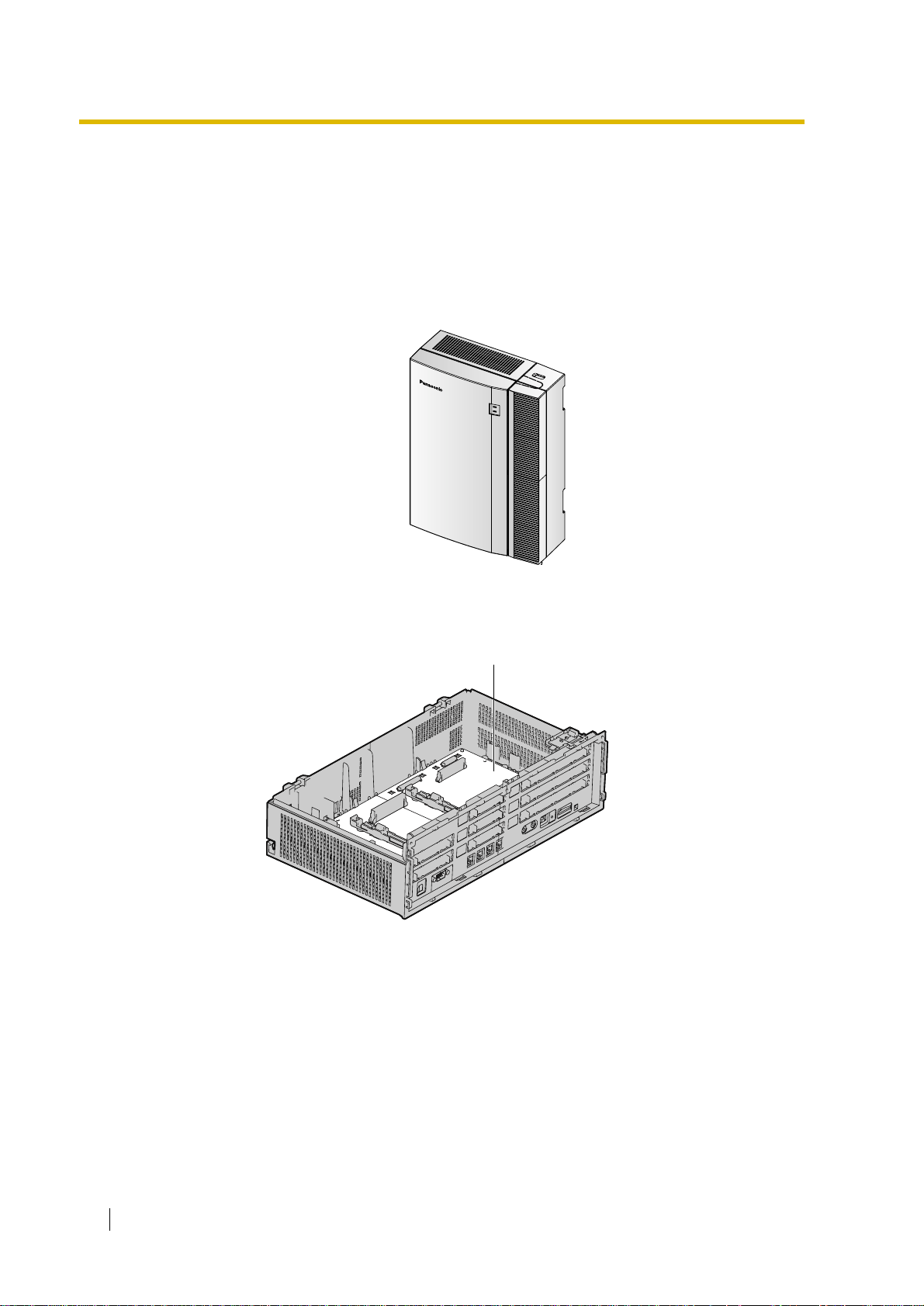
1.2.1 Main Unit
The main unit is equipped with 4 hybrid extension ports. For system expansion, optional
service cards can be installed, and an additional AC adaptor can also be connected.
Construction of Main Unit
Main Board
Main Unit
18 Installation Manual
Page 19
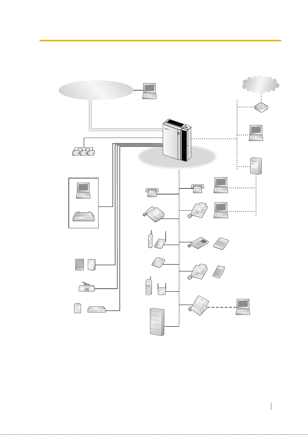
1.2.2 System Connection Diagram
Trunk (Telephone Company Lines)
Analogue/BRI
Remote PC
1.2 Basic System Construction
IP-type
Private Network
Batteries
PC
Printer
Hybrid IP-PBX
SLT
Fax Machine
Wireless Phone
SLT
DPT
APT
Router
PC
Server PC
PC
PC
Doorphone & Door Opener
BGM/Music On Hold (MOH)
Pager/
Speaker
Amplifier
ISDN Telephone
CSPS
Voice Processing
System
DPT
KX-T7636/
KX-T7633
USB
PC
Installation Manual 19
Page 20
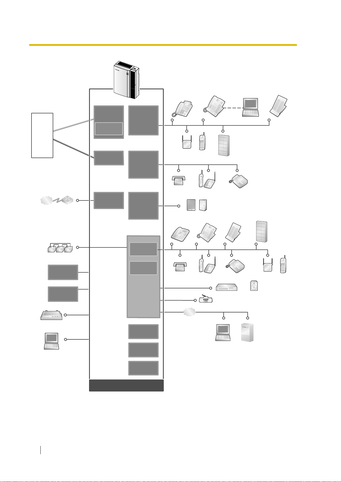
1.2 Basic System Construction
ISDN BRI Line
(Digital Trunk)
Analogue
Trunk
Hybrid IP-PBX
Telephone
Company
IP-type
Private Network
Batteries
AC Adaptor
Analogue
Analogue
Trunk
Trunk
ISDN BRI Line
ISDN BRI Line
(Digital Trunk)
(Digital Trunk)
Router
LCOT4
(KX-TDA3180)
CID4
(KX-TDA3193)
BRI2
(KX-TDA3284)
IP-GW4
(KX-TDA3480)
DLC8
(KX-TDA3172)
DLC4
(KX-TDA3171)
SLC8
(KX-TDA3174)
SLC4
(KX-TDA3173)
DPH4
(KX-TDA3161)
DPH2
(KX-TDA3162)
4 Hybrid
Extension Port
RMT
(KX-TDA3196)
DPT
CS PS
SLT Wireless Phone Fax Machine
Doorphone & Door Opener
APT DPT DSS Console
SLT Wireless Phone Fax Machine
PCKX-T7636/KX-T7633 DSS
Voice
Processing
System
Console
Voice
Processing
System
CS PS
Optional
AC Adaptor
Station Message
Detail Recording (SMDR)
PC
20 Installation Manual
Main Board
ECOH8
(KX-TDA3166)
EXT-CID
(KX-TDA3168)
MSG2
(KX-TDA3191)
Mountable Equipment
LAN
Radio
Amplifier Pager/Speaker
PC
Server PC
Page 21

1.3 Options
1.3 Options
1.3.1 Options
Model No. Model Name Description Maximum Quantity
KX-TDA3161 4-Port Doorphone Card
(DPH4)
KX-TDA3162 2-Port Doorphone Card
(DPH2)
KX-TDA3166 8-Channel Echo
Canceller Card (ECHO8)
KX-TDA3168 Extension Caller ID Card
(EXT-CID)
KX-TDA3171 4-Port Digital Extension
Card (DLC4)
KX-TDA3172 8-Port Digital Extension
Card (DLC8)
KX-TDA3173 4-Port Single Line
Telephone Extension
Card (SLC4)
KX-TDA3174 8-Port Single Line
Telephone Extension
Card (SLC8)
4-port doorphone card for 4 doorphones,
4 door openers (relays) and 4 sensors.
2-port doorphone card for 2 doorphones,
2 door openers, 4 relays, and 4 sensors.
8-channel card for echo cancellation in
the Conference Mode.
Sends Caller ID signal for extension
ports.
4-port digital extension card for DPTs,
DSS consoles, DPT Interface CSs, and
VM.
8-port digital extension card for DPTs,
DSS consoles, DPT Interface CSs, and
VM.
4-port extension card for SLTs. 1
8-port extension card for SLTs. 2
1
1
1
1
1
2
KX-TDA3180 4-Port Analogue Trunk
Card (LCOT4)
KX-TDA3191 2-Channel Message
Card (MSG2)
KX-TDA3193 4-Port Caller ID Card
(CID4)
KX-TDA3196 Remote Card (RMT) Analogue modem card for remote
KX-TDA3280 2-Port BRI Card (BRI2) 2-port ISDN Basic Rate Interface card
KX-TDA3480 4-Channel VoIP Gatewa y
Card (IP-GW4)
4-port analogue Trunk card. Only two
ports of the first installed LCO T4 card are
available in the event of power failure.
2-channel message card. 2
4-port Caller ID signal type FSK/FSK
(with Call Waiting Caller ID [Visual Caller
ID])/DTMF . To be mounted on the LCOT4
card.
communication with the Hybrid IP-PBX.
V90 support.
with 1 power failure transfer port. EUROISDN/ETSI compliant.
4-channel VoIP gatewa y card. VoIP
H.323 V.2, ITU-T G.729a, G.723.1 and
G.711 compliant.
3
3
1
3
1
Installation Manual 21
Page 22

1.3 Options
Model No. Model Name Description Maximum Quantity
KX-A236 Additional AC Adaptor
and AC Cord
AC adaptor and AC cord for system
expansion.
1
22 Installation Manual
Page 23

1.4 Specifications
1.4.1 General Description
Switching Non Blocking Distributed Time Switch
AC Adaptor AC Input 100 V AC to 240 V AC, 1.5 A, 50 Hz/60 Hz
DC Output 40 V, 1.38 A (55.2 W)
DC Input • DC IN 1: 40 V, 1.38 A (55.2 W)
• DC IN 2: 40 V, 1.38 A (55.2 W)
1.4 Specifications
Maximum Power Failure
Tolerance
Memory Backup Duration 7 years
Dialling Trunk Dial Pulse (DP) 10 pps, 20 pps
Extension Dial Pulse (DP) 10 pps, 20 pps
Connectors Trunk RJ45/RJ11 (2 wire) × each trunk port
Extension RJ45/RJ11 (4 wire) × each extension port
Paging Output 1 conductor jack
External MOH
Output
Mode Conversion DP-DTMF, DTMF-DP
Ring Frequency 20 Hz/25 Hz (selectable)
Central Office Loop Limit
Operating
Environment
Temperature 0 °C to 40 °C
Humidity 10 % to 90 % (non condensing)
300 ms
Tone (DTMF) Dialling
Tone (DTMF) Dialling
1 conductor jack
1600 maximum
Conference Call Trunk From 5 × 3-party conference call to 2 × 8-party conference call
Music on Hold (MOH) 1 port (Level Control: -6 dB to +6 dB in 3 dB steps)
Selectable Tone/External Music Source port
Paging Internal Level Control: -6 dB to +3 dB in 3 dB steps
External 1 port (Volume Control: -15 dB to +6 dB in 3 dB steps)
Serial Interface
Port
RS-232C 1 (max 115.2 kbps)
USB 1
Installation Manual 23
Page 24

1.4 Specifications
Extension Connection Cable SLT 1 pair wire (T, R)
DPT 1-pair wire (D1, D2) or
2-pair wire (T, R, D1, D2)
APT 2-pair wire (T, R, D1, D2)
DSS Console and Add-on Key Module 1-pair wire (D1, D2)
Dimension 275 mm (W) × 376 mm (H) × 117 mm (D)
Weight (when fully mounted) Under 3.5 kg
24 Installation Manual
Page 25
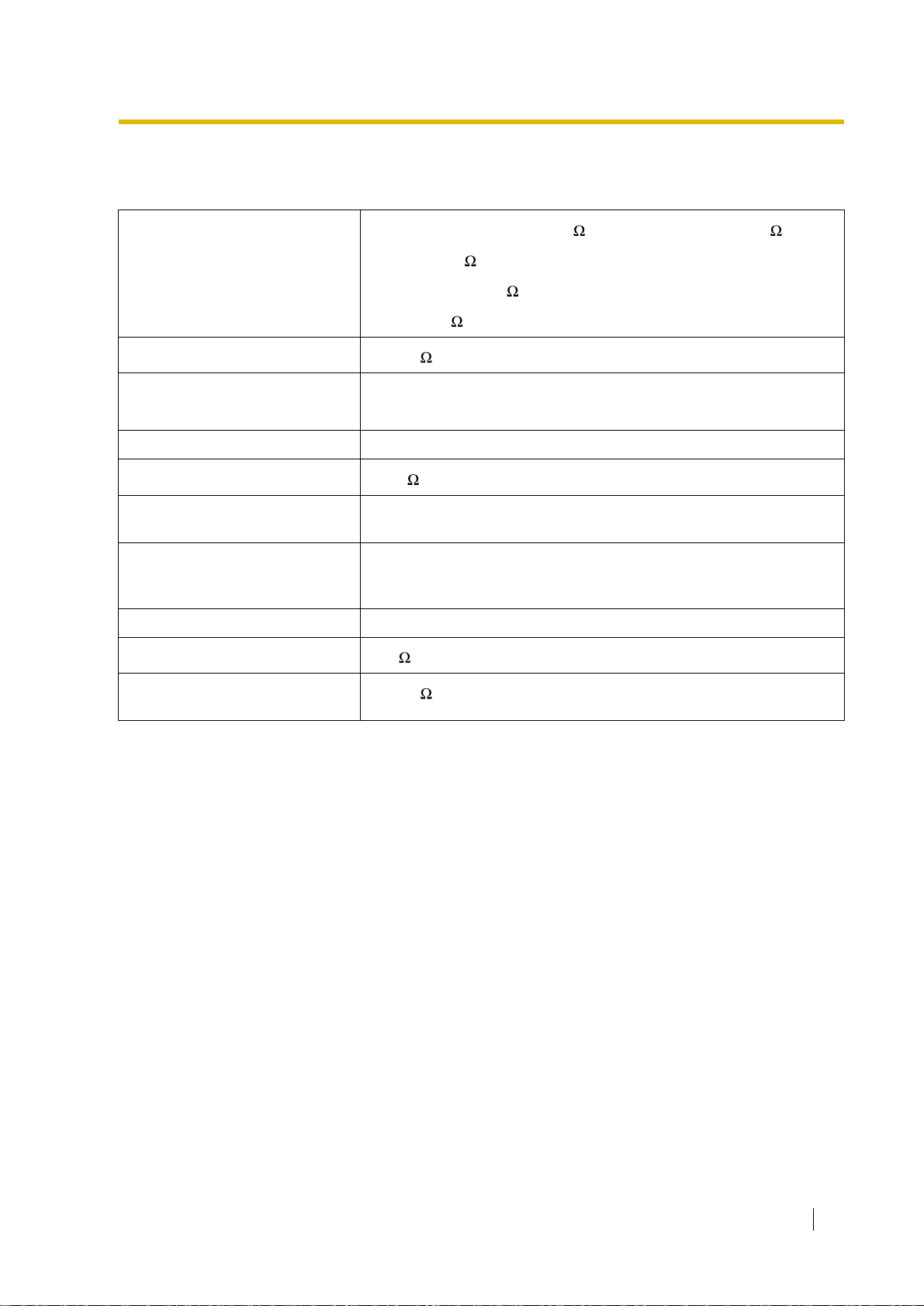
1.4.2 Characteristics
1.4 Specifications
Terminal Equipment Loop Limit
Minimum Leakage Resistance
Maximum Number of Extension
Instruments per Line
Ring Voltage 75 Vrms at 20 Hz/25 Hz depending on the Ringing Load
Trunk Loop Limit
Hookswitch Flash/Recall
Timing Range
BRI Cards Internal ISDN Mode Supply Voltage: 40 V
Door Opener Current Limit 24 V DC/30 V AC, 1 A maximum
Paging Terminal Impedance
• PT: KX-T7600 series: 90 ; all other DPTs/APTs: 40
• SLT: 600 including set
• Doorphone: 20
• CS: 65
15 000 maximum
1 for PT or SLT
2 by Parallel or eXtra Device Port connection of a PT and an SLT
1600 maximum
24 ms to 2032 ms
Power Supply: 4.5 W per 1 line, 5 W per 2 lines (Under consideration)
Power Supply Method: Phantom Power Supply
600
MOH (Music on Hold) Terminal
Impedance
10 000
Installation Manual 25
Page 26
1.4 Specifications
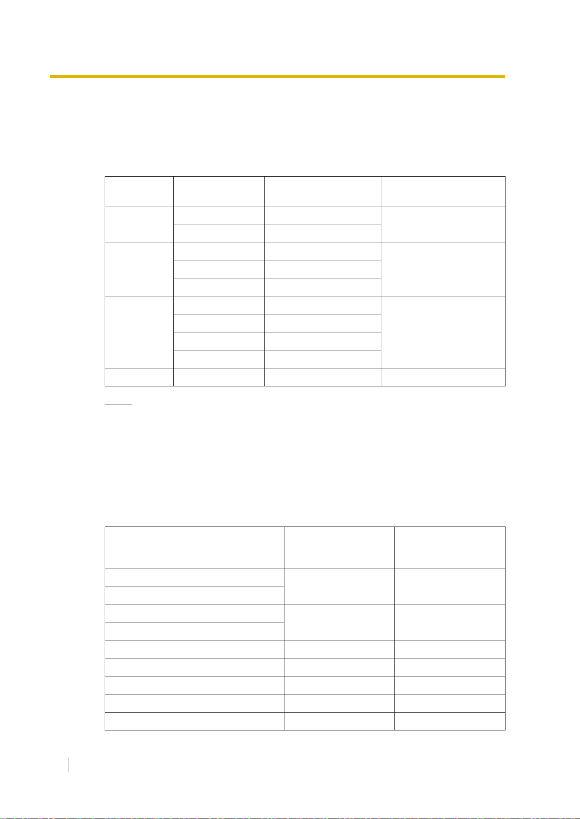
1.4.3 System Capacity
Maximum Number of Cards for Each Slot
The following number of trunk and extension cards can be installed in the Hybrid IP-PBX for
expansion.
Slot Type Card Type Total Number of Cards Total Number of Cards for
Slot
Semi Free
DLC8+SLC8 2
IP-GW4 1
DLC4/SLC4 1
Specified
LCOT4 3
MSG2 2
DPH4/DPH2 1
Option
ECHO8 1
EXT-CID 1
RMT RMT 1 1
Notes
• For each card, a maximum number that can be installed in the Hybrid IP-PBX is listed
in "1.3.1 Options".
• Any card that exceeds the capacity of the Hybrid IP-PBX will be ignored.
• When the Hybrid IP-PBX starts up with an invalid configuration mode, some cards will
be ignored.
Maximum Terminal Equipment
The following number of terminal equipment can be supported by the Hybrid IP-PBX.
3
3BRI2 3
4
SLT
DPT (KX-T7600 series)
DPT (KX-T7200, KX-T7400)
APT
CS 4 8
PS 28 28
VM 1 1
Doorphone 4 4
Door Opener 4 4
26 Installation Manual
Terminal Equipment Type With the Supplied AC
Adaptor only
24 (Total) 24 (Total)
4 (Total) 24 (Total)
With the Supplied AC
Adaptor and an
Additional AC Adaptor
Page 27

1.4 Specifications
Terminal Equipment Type With the Supplied AC
Adaptor only
SLT+DPT+APT+CS+VM
DPT (KX-T7200, KX-T7400)+APT+CS
*1
The maximum number of each terminal equipment is described above.
28
8
With the Supplied AC
Adaptor and an
Additional AC Adaptor
*1
*1
28
*1
24
Installation Manual 27
Page 28

1.4 Specifications
28 Installation Manual
Page 29

Section 2
Installation
This section describes the procedures to install the
Hybrid IP-PBX. Detailed instructions for planning the
installation site, installing the shelves and optional
service cards, and cabling of peripheral equipment are
provided. Further information on system expansion and
peripheral equipment installation is included.
Installation Manual 29
Page 30

2.1 Before Installation
2.1 Before Installation
2.1.1 Before Installation
Please read the following notes concerning installation and connection before installing the
Hybrid IP-PBX. Be sure to comply with applicable local regulations (e.g., law, guidelines).
Safety Installation Instructions
When installing telephone wiring, basic safety precautions should always be followed to reduce
the risk of fire, electric shock and injury to persons, including the following:
1. Never install telephone wiring during a lightning storm.
2. Never install telephone jacks in wet locations unless the jack is specifically designed for
wet locations.
3. Never touch uninsulated telephone wires or terminals unless the telephone line has been
disconnected at the network interface.
4. Use caution when installing or modifying telephone lines.
5. Anti-static precautions should be taken during installation.
Installation Precautions
This set is made for wall mounting. Avoid installing in the following places. (Doing so may result
in malfunction, noise, or discolouration.)
1. In direct sunlight and hot, cold, or humid places.
Temperature range: 0 °C to 40 °C
2. Sulphuric gases produced in areas where there are thermal springs, etc. may damage the
equipment or contacts.
3. Places in which shocks or vibrations are frequent or strong.
4. Dusty places, or places where water or oil may come into contact with the unit.
5. Near high-frequency generating devices such as sewing machines or electric welders.
6. On or near computers, telexes, or other office equipment, as well as microwave ovens or
air conditioners. (It is preferable not to install in the same room with the above equipment.)
7. Closer than 1.8 m from radios and televisions (both the Hybrid IP-PBX and PTs).
8. Do not obstruct the area around the Hybrid IP-PBX (for reasons of maintenance and
inspection—be especially careful to allow space of at least 20 cm for cooling above and at
least 10 cm at the sides of the Hybrid IP-PBX).
9. Do not block the openings at top of the Hybrid IP-PBX.
10. Do not stack up the optional service cards.
Wiring Precautions
Be sure to follow these instructions when wiring.
1. Do not wire the telephone cable in parallel with an AC power source, computer, telex, etc.
If the cables are run near those wires, shield the cables with metal tubing or use shielded
cables and ground the shields.
2. If cables are run on the floor, use protectors to prevent the wires from being stepped on.
Avoid wiring under carpets.
30 Installation Manual
Page 31

2.1 Before Installation
3. Avoid using the same power supply outlet for computers, telexes, and other office
equipment. Otherwise, Hybrid IP-PBX operation may be interrupted by the induction noise
from such equipment.
4. Please use 1-pair telephone wire for extension connection of (telephone) equipment such
as standard telephones, data terminals, answering machines, computers, Voice
Processing Systems, etc., except PTs (e.g., KX-T7600 series).
5. The power switch of the Hybrid IP-PBX must be off during wiring. After the wiring is
completed, turn the power switch on.
6. Mis-wiring may cause the Hybrid IP-PBX to operate improperly.
7. If an extension does not operate properly, disconnect the telephone from the extension line
and then connect again, or turn the power to the Hybrid IP-PBX off and on again.
8. The Hybrid IP-PBX is equipped with a 3-wire earthing type plug. This is a safety feature.
If you are unable to insert the plug into the outlet, contact your electrician to replace your
obsolete outlet. Do not defeat the purpose of the earthing-type plug.
9. Use twisted pair cable for trunk connection.
10. Trunks should be installed with lightning protectors. For details, refer to "2.2.11 Lightning
Protector Installation".
Installation Manual 31
Page 32

2.2 Installation of the Hybrid IP-PBX
2.2 Installation of the Hybrid IP-PBX
2.2.1 Unpacking
Unpack the box and check the items below:
Main Unit 1
AC Cord 1
AC Adaptor 1
Screws for Wall Mounting 5
Washers 5
Mini Plug (for pager and music source) 2
SD Memory Card 1
Strap 1
32 Installation Manual
Page 33

2.2.2 Names and Locations
2.2 Installation of the Hybrid IP-PBX
SD Memory
Card Slot
Reset Button
System Clear Switch
Pager port
MOH port
Ground
Terminal
Battery
Connector
DC IN 2
DC IN 1
Notes
• DC IN 1: Used for an AC adaptor which is supplied with the Hybrid IP-PBX.
• For details about connecting peripherals, refer to "2.10.1 Connection of Peripherals".
• For details about System Clear Switch, refer to "2.12.1 Starting the Hybrid IP-PBX".
• For details about Reset Button, refer to "4.1.4 Using the Reset Button".
Inside View
Hybrid Extension
Ports
RS232C port
USB port
Power Switch
DC IN 2: Used for an additional AC adaptor.
RMT Card Slot
Option Slots 8 to 11
(from the bottom)
Specified Slots 2 to 4
(from the bottom)
Semi Free Slots 5 to 7
(from the bottom)
Installation Manual 33
Page 34

2.2 Installation of the Hybrid IP-PBX
2.2.3 Opening/Closing the Covers
Opening the Covers
1. Move the slide button to the right, and slide the cable cover upwards. Then remove the
cable cover by rotating it in the direction of the arrow.
Slide Button
2. Loosen three screws.
34 Installation Manual
Page 35

2.2 Installation of the Hybrid IP-PBX
2
1
3. Open the front cover, holding the protrusions on the both sides of the front cover.
4. Remove the front cover, pushing it in the direction of the arrow.
Installation Manual 35
Page 36

2.2 Installation of the Hybrid IP-PBX
Closing the Covers
1. Fit the front cover to the main unit as shown below, and then close the front cover.
2. Tighten three screws.
Screw
36 Installation Manual
Page 37

2.2 Installation of the Hybrid IP-PBX
3. Fit the protrusions on the cable cover to the receptacles on the main unit.
4. Slide the cable cover in the direction of the arrow until it locks.
Installation Manual 37
Page 38

2.2 Installation of the Hybrid IP-PBX
LOCK
2.2.4 Installation of the SD Memory Card
SD Memory Card Slot
L
O
C
K
SD Memory Card
CAUTION
• Use only the SD Memory Card included with the Hybrid IP-PBX.
• SD Memory Card contains software for all processes of the Hybrid IP-PBX and all
customer data. The SD Memory Card must be inserted before start up.
• Do not remove the SD Memory Card during the operation of the Hybrid IP-PBX.
Removing SD Memory Card during the operation may cause damage to the SD
Memory Card, or result in loss of data.
LED Indications
Colour Description
Green SD memory card status
• ON: Accessing
38 Installation Manual
Page 39

2.2.5 Frame Earth Connection
IMPORTANT
Connect the frame of the Hybrid IP-PBX to earth.
1. Loosen the screw.
2. Insert an earthing wire (user-
supplied)*.
3. Tighten the screw.
4. Connect the earthing wire to
earth.
* For earthing wire, green-and-yellow insulation is required, and the cross-sectional area of
the conductor must be more than 0.75 mm
Screw
Earthing
wire
To Earth
2
or 18 AWG.
2.2 Installation of the Hybrid IP-PBX
• Be sure to comply with applicable local regulations (e.g., law, guidelines).
• Proper earthing (connection to earth) is very important to protect the Hybrid IP-PBX from
the bad effects of external noise or to reduce the risk to the user of electrocution in the
case of lightning strike.
• The earthing wire of the AC cable has an effect against the external noise and lightning
strikes, but it may not be enough to protect the Hybrid IP-PBX. A permanent connection
between earth and the earth terminal of the Hybrid IP-PBX must be made.
Installation Manual 39
Page 40

2.2 Installation of the Hybrid IP-PBX
2.2.6 Backup Batteries Connection
The backup batteries and Back-up Battery Cable provide backup power supply to allow full use
of the Hybrid IP-PBX in the event of a power failure. In case of power failure, the backup
batteries automatically maintain the power for the Hybrid IP-PBX without interruption.
Be sure to comply with applicable local regulations (e.g., law, guidelines).
1. Turn off the power switch of the Hybrid IP-PBX.
2. Connect the Back-up Battery Cable with 3 identical VRLA (Valve Regulated Lead Acid)
batteries (12 V DC × 3).
Battery Connector
Back-up Battery Cable
Fuse
Power Switch
Red
Backup Batteries (12 V DC x 3)
• Turn on the power switch of the Hybrid IP-PBX only after the installation of the Hybrid IPPBX is finished and AC power is turned on.
• For 1 backup battery, battery capacity of 28 Ah or below is recommended (otherwise, the
backup battery may not be charged).
• Make sure that the type and capacity of the 3 backup batteries are identical.
• The Back-up Battery Cable should not be exposed to direct sunlight. Keep the Back-up
Battery Cable and the backup batteries away from heating appliances and fire. Place the
backup batteries in ventilated place.
• For details about the backup batteries, refer to the manual intended for the batteries.
Black
CAUTION
• Make sure that the polarities of the backup batteries and wiring are correct.
• Make sure that you do not short the backup batteries or cables.
• There is a danger of explosion if backup batteries are incorrectly replaced. Replace
only with the same or equivalent type recommended by the manufacturer. Dispose of
used batteries according to the manufacturer’s instructions.
• Use the correct type of Back-up Battery Cable.
40 Installation Manual
Page 41

2.2 Installation of the Hybrid IP-PBX
2.2.7 Installing/Removing the Optional Service Cards
Slot Condition
Slot Type Card Type
Semi Free Slots DLC8, SLC8, IP-GW4
Specified Slots DLC4, SLC4, BRI2, LCOT4
Option Slots MSG2, DPH4, DPH2, ECHO8, EXT-CID
RMT Slot RMT
CAUTION
To protect the main board from static electricity, do not touch parts on the main board in
the main unit and on the optional service cards. T o discharge static, touch ground or wear
an earthing strap.
Installing Optional Service Cards
1. Before installing the optional service cards, cut and remove the appropriate dummy cover
plates of the cabinet. For safety reasons, smooth the cut edges.
Dummy Cover Plate
Installation Manual 41
Page 42

2.2 Installation of the Hybrid IP-PBX
2. Install the card as follows.
3. Insert the extension bolt into the hole of the card, and tighten it for secure the card.
1
2
42 Installation Manual
Page 43

Removing the Optional Service Cards
1. Untighten the extension bolt.
2. Pull the card in the direction of the arrow, holding the protrusions of the card.
2.2 Installation of the Hybrid IP-PBX
Installation Manual 43
Page 44

2.2 Installation of the Hybrid IP-PBX
2.2.8 Types of Connectors
Connector Type Pin Number Used for
RJ45
(Twisted pair cable)
RJ11
(Twisted pair cable)
• DLC4 (KX-TDA3171NE)
• DLC8 (KX-TDA3172NE)
• SLC4 (KX-TDA3173NE)
8
• SLC8 (KX-TDA3174NE)
• LCOT4 (KX-TDA3180NE)
1
• DPH4 (KX-TDA3161NE)
• DPH2 (KX-TDA3162)
• BRI2 (KX-TDA3280)
• IP-GW4 (KX-TDA3480)
• Main Board (Hybrid Extension Ports)
• DLC4 (KX-TDA3171)
• DLC8 (KX-TDA3172)
• SLC4 (KX-TDA3173)
1
• SLC8 (KX-TDA3174)
4
• LCOT4 (KX-TDA3180)
• DPH4 (KX-TDA3161)
• Main Board (Hybrid Extension Ports)
Notice
In certain countries/areas, the RJ11 connector is
used for the hybrid extension ports.
10-pin
Terminal
Block
RS-232C
8-pin
Terminal
Block
1
10
1 6
5 9
• DPH4 (KX-TDA3161)
• DPH2 (KX-TDA3162)
1
8
• Main Board
44 Installation Manual
Page 45

2.2 Installation of the Hybrid IP-PBX
Connector Type Pin Number Used for
• Main Board
USB
Mini Plug
1
2
4
3
• Main Board (Pager port, MOH port)
+
-
Installation Manual 45
Page 46

2.2 Installation of the Hybrid IP-PBX
2.2.9 Wall Mounting (KX-TDA30)
CAUTION
Drive mounting screws into the wall. Be careful to avoid touching any metal laths, wire
laths or metal plates in the wall.
1. Place the reference for wall mounting on the last page of this manual on the wall to mark
three screw positions.
130 mm
250 mm
2. Install the screws and washers (included) to the wall.
Washer
Drive the screw
to this position
Notes
• Make sure that the screw heads are at the same distance from the wall.
• Install the screws perpendicular to the wall.
Wooden
Wall
3. Hook the main unit on the screw heads.
Notes
• Do not block the openings of the cabinet. Allow space of at least 10 cm above and at
• Make sure that the wall behind the cabinet is flat and free of obstacles, so that the
• Make sure that the wall behind the cabinet is not made of wood.
46 Installation Manual
the sides of the cabinet.
openings on the back of the cabinet will not be blocked.
Page 47

• Be careful not to drop the cabinet.
2.2 Installation of the Hybrid IP-PBX
Installation Manual 47
Page 48

2.2 Installation of the Hybrid IP-PBX
2.2.10 Wall Mounting (AC Adaptor)
CAUTION
Drive mounting screws into the wall. Be careful to avoid touching any metal laths, wire
laths or metal plates in the wall.
1. Place the reference for wall mounting on the following page on the wall to mark two screw
positions.
110 mm
2. Install the screws and washers (included) to the wall.
Washer
Drive the screw
to this position
Notes
• Make sure that the screw heads are at the same distance from the wall.
• Install the screws perpendicular to the wall.
Wooden
Wall
3. Hook the AC adaptor on the screw heads.
Note
Be careful not to drop the AC Adaptor.
48 Installation Manual
Page 49

Reference for Wall Mounting
Please copy this page and use as a reference for wall mounting.
Install a screw here.
110 mm
2.2 Installation of the Hybrid IP-PBX
Install a screw here.
Note
When you print out this page, the distance on the paper output may deviate slightly
fromthe number indicated above.
Installation Manual 49
Page 50

2.2 Installation of the Hybrid IP-PBX
2.2.11 Lightning Protector Installation
Overview
A lightning protector is a device to be installed on a trunk to prevent a dangerous surge from
entering the building and damaging equipment.
A dangerous surge can occur if a telephone line comes in contact with a power line. Trouble
due to lightning surges has been showing a steady increase with the development of electronic
equipment.
In many countries/areas, there are regulations requiring the installation of lightning protection.
A lightning strike to a telephone cable which is 10 m above ground can be as high as 200 000 V.
The Hybrid IP-PBX should be installed with lightning protectors. In addition, earthing
(connection to earth) is very important for the protection of the Hybrid IP-PBX.
Be sure to comply with applicable local regulations (e.g., law, guidelines).
Recommended Lightning Protectors
• KX-A207
• TELESPIKE BLOK MODEL TSB (TRIPPE MFG. CO.)
• SPIKE BLOK MODEL SK6-0 (TRIPPE MFG. CO.)
• Krone 237A strips fitted with 14A/1 surge arrestors
• Super MAX™ (PANAMAX)
• MP1 (ITW LINK)
Installation
Trunk Trunk Trunk
Earth
Lightning
Protectors
Terminal
Board
Extn. Extn.
SLT
PT
CS
Extn.
Extn.: Extension line
Hybrid
IP-PBX
Frame
Earth
50 Installation Manual
Page 51

Outside In sta llation
2.2 Installation of the Hybrid IP-PBX
(Main Building)
Trunk
If you install an extension outside of the main building, the following precautions are
recommended:
Lightning Protectors
Trunk
Terminal
Board
Extn.
Extn.
Extn.
CSSLT PT
Hybrid
IP-PBX
Extn.
Lightning
Protector
Earth
(Another Building)
SLT
PT
CS
Extn.: Extension Line
a. Install the extension wire underground.
b. Use a conduit to protect the wire.
Note
The lightning protector for an extension and CS is different from that for trunks.
Installation of an Earth Rod
Lightning Protector
Trunk
Earthing
Wire
(Underground)
Earth Rod
Hybrid
IP-PBX
Installation Manual 51
Page 52

2.2 Installation of the Hybrid IP-PBX
1. Installation location of the earth rod.....Near the protector
2. Check obstructions.....None
3. Composition of the earth rod.....Metal
4. Depth of the earth rod.....More than 50 cm
5. Cross sectional area of the earthing wire.....More than 1.3 mm
Notes
• The above figures are recommendations only.
• The length of earth rod and the required depth depend on the composition of the soil.
2
52 Installation Manual
Page 53

2.3 Installation of the Trunk Cards
2.3 Installation of the Trunk Cards
2.3.1 LCOT4 Card
Function
4-port analogue T runk card. Only two ports of the first installed LCOT4 card are available in the
event of power failure. To be installed in the Specified Slot. One CID4 card can be mounted on
the LCOT4 card (refer to "2.3.2 CID4 Card" ).
To trunk
Accessory and User-supplied Items
Accessory (included): Extension Bolt × 1, Strap × 1
User-supplied (not included): RJ45 connector/RJ11 connector
Notice
• The connector type may be RJ45 or RJ11 depending on the country/area.
• Shown above is a card having the RJ45 connectors.
Note
To confirm the trunk connection, refer to "Confirming the Trunk Connection" in "2.12.1
Starting the Hybrid IP-PBX".
Installation Manual 53
Page 54

2.3 Installation of the Trunk Cards
RJ45 Connector Pin Assignments
No. Signal Name Function
1/9 Reserved –
16
2/10 Reserved –
3/11 Reserved –
9
4/12 T Tip
8
5/13 R Ring
1
6/14 Reserved –
7/15 Reserved –
8/16 Reserved –
RJ11 Connector Pin Assignments
No. Signal Name Function
1 Reserved –
1
2R Ring
4
3T Tip
4 Reserved –
54 Installation Manual
Page 55

2.3.2 CID4 Card
Function
4-port Caller ID signal type FSK/FSK (with Call Waiting Caller ID [Visual Caller ID])/DTMF. T o
be mounted on the LCOT4 card.
CID4 Card
2.3 Installation of the Trunk Cards
LCOT4 Card
Accessory and User-supplied Items
Accessory (included): none
User-supplied (not included): none
Note
Only 1 CID4 card can be mounted on the LCOT4 card.
Installation Manual 55
Page 56

2.3 Installation of the Trunk Cards
2.3.3 BRI2 Card
Function
2-port ISDN Basic Rate Interface card with 1 power failure transfer port. EURO-ISDN/ETSI
compliant.
AB
RJ45
(LINE1, LINE2)
To NT1/Extension
LEDs
(1 to 2)
Accessory and User-supplied Items
Accessory (included): Extension Bolt × 1, Strap × 1
User-supplied (not included): RJ45 connector
Notes
• When connecting these optional service cards to the trunk, connect through NT1; do
not connect to the trunk directly.
• This optional service card has 100 of terminal resistance. For use of point to multi-
point connection, the card must be placed at the end of the bus.
• This optional service card can be used for either trunk or extension connection, by
setting the A/B switch or using the connector with appropriate pin assignments.
• For details about power failure transfer , refer to "2.11.1 Auxiliary Connection for Power
Failure Transfer".
• T o confirm the trunk connection, refer to "Confirming the T runk Connection" in "2.12.1
Starting the Hyb rid IP-PBX".
Notice
If the connected ISDN terminal has no external power source, make sure that the power
is supplied from the BRI2 card by programming the Hybrid IP-PBX accordingly.
However, if there is an external power source to the terminal, make sure that there is no
power supplied to the terminal from the BRI2 card. Failure to do so may cause damage to
the power supply circuit of the BRI2 card or the terminal.
Switch Settings
Switch Type Usage and Status Definition
A/B Slide Select A (default) for trunk or B for extension use.
56 Installation Manual
Page 57

Pin Assignments
RJ45 Connector for Trunk Use
No. Signal Name Level [V] Function
1-2 Reserved ––
3 TX1 (+) Transmit data 1
8
4 RX2 (+) Receive data 2
5 RX1 (-) Receive data 1
1
6 TX2 (-) Transmit data 2
7-8 Reserved ––
RJ45 Connector for Extension Use
No. Signal Name Level [V] Function
1-2 Reserved ––
2.3 Installation of the Trunk Cards
3 RX2 (+) Receive data 2
8
4 TX1 (+) Transmit data 1
5 TX2 (-) Transmit data 2
1
6 RX1 (-) Receive data 1
7-8 Reserved ––
LED Indications
Colour Description
1 Green LINE 1 status indication
• OFF: L1 asynchronous
• ON: Synchoronous/L2 link established/clock slave
• Flash: Refer to "LINE LED Flash Pattern" below for details.
2 Green LINE 2 status indication
• OFF: L1 asynchronous
• ON: Synchoronous/L2 link established/clock slave
• Flash: Refer to "LINE LED Flash Pattern" below for details.
LINE LED Flash Pattern
L1 L2 Master
Clock
ON OFF OFF
Flash Pattern
1 s
Installation Manual 57
Page 58

2.3 Installation of the Trunk Cards
L1 L2 Master
Clock
ON OFF ON
ON ON ON
L1: ON (Synchronous)
L2: ON (Link established)/OFF (Link not established)
Master Clock: ON (Master)/OFF (Slave)
1 s
1 s
Flash Pattern
Maximum Cabling Distance of S0 Bus Connection
The maximum distance of the extension cable that connects the Hybrid IP-PBX and the ISDN
terminal equipment (TE) is shown below:
Under 1000 m
Point-to-Point
Under 150 m
TE 1 TE 8
Under 500 m Under 50 m
TE
Point-to-Multipoint
Expansion
Point-to-Multipoint
TE 8TE 1
58 Installation Manual
Page 59

2.3.4 IP-GW4 Card
Function
4-channel VoIP gateway card. VoIP H.323 V.2, ITU-T G.729a, G.723.1 and G.711 compliant.
RJ45 (10BASE-T/
100BASE-TX)
To IP-type private
network
2.3 Installation of the Trunk Cards
LEDs
(1 to 4,
from the right)
Accessory and User-supplied Items
Accessory (included): Extension Bolt × 1, Strap × 1
User-supplied (not included): RJ45 connector
Notes
• Maximum length of the Ethernet (10BASE-T/100BASE-TX) cable to be connected to
this optional service card is 100 m.
• For programming instructions and other information of the IP-GW4 card, refer to the
manual for the IP-GW4 card.
• T o confirm the trunk connection, refer to "Confirming the T runk Connection" in "2.12.1
Starting the Hybrid IP-PBX".
Pin Assignments
RJ45 Connector (10BASE-T/100BASE-TX)
No. Signal Name Input (I)/Output (O) Function
1 TPO+ O Transmit data+
2 TPO- O Transmit data-
8
3TPI+ I Receive data+
4-5 Reserved ––
1
6TPI- I Receive data7-8 Reserved ––
Installation Manual 59
Page 60

2.3 Installation of the Trunk Cards
LED Indications
Colour Description
1 Green On-line status indication
• OFF: On-line mode
• Flash: Emergency maintenance mode
2 Red Alarm detection status indication
• ON: Alarm
• OFF: Normal
3 Green Lin k stat us in dication
• ON: Normal Connection
• OFF: Connection Error
4 Green Data transmission status indication
• ON: Data transmitting
• OFF: No data transmitted
60 Installation Manual
Page 61

2.4 Installation of the Extension Cards
2.4 Installation of the Extension Cards
2.4.1 DLC4 Card
Function
4-port digital extension card for DPTs, DSS consoles, DPT Interface CSs, and VM.
To extension
Accessory and User-supplied Items
Accessory (included): Extension Bolt × 1, Strap × 1
User-supplied (not included): RJ45 connector/RJ11 connector
Notice
The connector type may be RJ45 or RJ11 depending on the country/area.
Shown above is a card having the RJ45 connectors.
Note
For details about connecting the CS, refer to "2.8.7 Connecting the Cell Station to the
Hybrid IP-PBX".
Installation Manual 61
Page 62

2.4 Installation of the Extension Cards
RJ45 Connector Pin Assignments
No. Signal Name Function
1/9 Reserved –
16
2/10 Reserved –
3/11 D2 Data port (Low Volt)
9
4/12 Reserved –
8
5/13 Reserved –
1
6/14 D1 Data port (High Volt)
7/15 Reserved –
8/16 Reserved –
RJ11 Connector Pin Assignments
No. Signal Name Function
1 D1 Data port (High Volt)
1
2 Reserved –
4
3 Reserved –
4 D2 Data port (Low Volt)
62 Installation Manual
Page 63

2.4.2 SLC4 Card
Function
4-port extension card for SLTs.
To extension
2.4 Installation of the Extension Cards
Accessory and User-supplied Items
Accessory (included): Extension Bolt × 1, Strap× 1
User-supplied (not included): RJ45 connector/RJ11 connector
Notice
The connector type may be RJ45 or RJ11 depending on the country/area.
Shown above is a card having the RJ45 connectors.
RJ45 Connector Pin Assignments
No. Signal Name Function
1/9 Reserved –
16
2/10 Reserved –
3/11 Reserved –
9
4/12 R Ring
8
5/13 T Tip
1
6/14 Reserved –
7/15 Reserved –
8/16 Reserved –
Installation Manual 63
Page 64

2.4 Installation of the Extension Cards
RJ11 Connector Pin Assignments
No. Signal Name Function
1 Reserved –
1
2T Tip
4
3R Ring
4 Reserved –
64 Installation Manual
Page 65

2.4.3 DLC8 Card
Function
8-port digital extension card for DPTs, DSS consoles, DPT Interface CSs, and VM.
2.4 Installation of the Extension Cards
To extensions
Accessory and User-supplied Items
Accessory (included): Extension Bolt × 1, Strap × 1
User-supplied (not included): RJ11 connector
Notice
The connector type may be RJ45 or RJ11 depending on the country/area.
Shown above is a card having the RJ45 connectors.
Note
For details about connecting the CS, refer to "2.8.7 Connecting the Cell Station to the
Hybrid IP-PBX".
Installation Manual 65
Page 66

2.4 Installation of the Extension Cards
RJ45 Connector Pin Assignments
No. S ignal Name Function
1/9/17/25 Reserved –
32
2/10/18/26 Reserved –
25
3/11/19/27 D2 Data port (Low Volt)
24
4/12/20/28 Reserved –
17
5/13/21/29 Reserved –
16
6/14/22/30 D1 Data port (High Volt)
9
7/15/23/31 Reserved –
8
8/16/24/32 Reserved –
1
RJ11 Connector Pin Assignments
No. Signal Name Function
1 D1 Data port (High Volt)
1
2 Reserved –
4
3 Reserved –
4 D2 Data port (Low Volt)
66 Installation Manual
Page 67

2.4.4 SLC8 Card
Function
8-port extension card for SLTs.
2.4 Installation of the Extension Cards
To extensions
Accessory and User-supplied Items
Accessory (included): Extension Bolt ×1, Strap × 1
User-supplied (not included): RJ45 connector/RJ11 connector
Notice
The connector type may be RJ45 or RJ11 depending on the country/area.
Shown above is a card having the RJ45 connectors.
RJ45 Connector Pin Assignments
No. Signal Name Function
1/9/17/25 Reserved –
32
2/10/18/26 Reserved –
25
3/11/19/27 Reserved –
24
4/12/20/28 R Ring
17
5/13/21/29 T Tip
16
6/14/22/30 Reserved –
9
7/15/23/31 Reserved –
8
8/16/24/32 Reserved –
1
Installation Manual 67
Page 68

2.4 Installation of the Extension Cards
RJ11 Connector Pin Assignments
No. Signal Name Function
1 Reserved –
1
2T Tip
4
3R Ring
4 Reserved –
68 Installation Manual
Page 69

2.5 Installation of the Other Cards
2.5 Installation of the Other Cards
2.5.1 DPH4 Card
Function
4-port doorphone card for 4 doorphones, 4 door openers (relays) and 4 sensors.
10-pin
8-pin
To sensors
To door openers
To doorphones
Accessory and User-supplied Items
Accessory (included): Extension Bolt × 1, 10-pin terminal block × 1, 8-pin terminal block
× 1, T elephone Line Cord × 2, T erminal Box × 1 (for DPH4 card with
RJ45 connectors) or 2 (for DPH4 card with RJ11 connectors) , Strap
× 1
User-supplied (not included): none
Notice
The connector type may be RJ45 or RJ11 depending on the country/area.
Shown above is a card having the RJ45 connectors. As compared to the RJ45 connectors,
the RJ11 connectors are upside down in position.
Note
For details about connection to doorphones and door openers, refer to "2.9.1 Connection
of Doorphones and Door Openers".
Telephone Line Cord
Installation Manual 69
Page 70

2.5 Installation of the Other Cards
Pin Assignments
RJ45 Connector
No. Signal Name Function
1-2 Reserved –
16
3 DP2 Doorphone 2 transmit
4 DP1 Doorphone 1 transmit
9
5 com1 Doorphone 1 receive
8
6 com2 Doorphone 2 receive
1
7-10Reserved –
11 DP4 Doorphone 4 transmit
12 DP3 Doorphone 3 transmit
13 com3 Doorphone 3 receive
RJ11 Connector
14 com4 Doorphone 4 receive
15-16Reserved –
No. Signal Name Function
1 DP2 Doorphone 2 transmit
2 DP1 Doorphone 1 transmit
8
5
3 com1 Doorphone 1 receive
4 com2 Doorphone 2 receive
4
5 DP4 Doorphone 4 transmit
1
6 DP3 Doorphone 3 transmit
7 com3 Doorphone 3 receive
8 com4 Doorphone 4 receive
70 Installation Manual
Page 71

8-pin T e rminal Block
2.5 Installation of the Other Cards
No. Signal Name Function
8
10-pin T e rminal Block
10
1
1 SENS 1a S ens or 1a
2 SENS 1b S ens or 1b
3 SENS 2a S ens or 2a
4 SENS 2b S ens or 2b
5 SENS 3a S ens or 3a
6 SENS 3b S ens or 3b
7 SENS 4a S ens or 4a
8 SENS 4b S ens or 4b
No. Signal Name Function
1 OP1b (RL 1b) Door opener 1 (Relay 1)
2 OP1a (RL 1a) Door opener 1 com (Relay 1 com)
3 OP2b (RL 2b) Door opener 2 (Relay 2)
4 OP2a (RL 2a) Door opener 2 com (Relay 2 com)
5 OP3b (RL 3b) Door opener 3 (Relay 3)
6 OP3a (RL 3a) Door opener 3 com (Relay 3 com)
7 OP4b (RL 4b) Door opener 4 (Relay 4)
8 OP4a (RL 4a) Door opener 4 com (Relay 4 com)
9-10Reserved –
Installation Manual 71
Page 72

2.5 Installation of the Other Cards
2.5.2 DPH2 Card
Function
2-port doorphone card for 2 doorphones, 2 door openers, 4 relays, and 4 sensors.
RJ45
10-pin
8-pin
To sensors
To door openers
To doorphones
Accessory and User-supplied Items
Accessory (included): Extension Bolt × 1, 10-pin terminal b loc k × 1, 8-pin terminal bloc k × 1
Telephone Line Cord × 2, Terminal Box × 1, Strap × 1
User-supplied (not included): none
Note
For details about connection to doorphones and door openers, refer to "2.9.1 Connection
of Doorphones and Door Openers".
Telephone Line Cord
72 Installation Manual
Page 73

Pin Assignments
RJ45 Connector
16
9
8
1
2.5 Installation of the Other Cards
No. Signal Name Function
1 OP1b Door opener 1
2 OP1a Door opener 1 com
3 Path_1b Doorphone 1 transmit
4 Path_1a Doorphone 1 receive
5 Call_1b Doorphone 1 call button
6 Call_1a Doorphone 1 call button com
7 DC1b Doorphone control 1
8 DC1a Doorphone control 1 com
9 OP2b Door opener 2
10 OP2a Door opener 2 com
8-pin T e rminal Block
8
1
11 Path_2b Doorphone 2 transmit
12 Path_2a Doorphone 2 receive
13 Call_2b Doorphone 2 call button
14 Call_2a Doorphone 2 call button com
15 DC2b Doorphone control 2
16 DC2a Doorphone control 2 com
No. Signal Name Function
1 SENS 1a S ens or 1a
2 SENS 1b S ens or 1b
3 SENS 2a S ens or 2a
4 SENS 2b S ens or 2b
5 SENS 3a S ens or 3a
6 SENS 3b S ens or 3b
7 SENS 4a S ens or 4a
8 SENS 4b S ens or 4b
Installation Manual 73
Page 74

2.5 Installation of the Other Cards
10-pin Terminal Block
No. Signal Name Function
10
1
1 RL1b Relay 1
2 RL1a Rela y 1 com
3 RL2b Relay 2
4 RL2a Rela y 2 com
5 RL3b Relay 3
6 RL3a Rela y 3 com
7 RL4b Relay 4
8 RL4a Rela y 4 com
9-10Reserved –
74 Installation Manual
Page 75

2.5.3 ECHO8 Card
Function
8-channel card for echo cancellation in the Conference Mode.
Accessory and User-supplied Items
Accessory (included): Extension Bolt × 1
User-supplied (not included): none
2.5 Installation of the Other Cards
Notes
• One Hybrid IP-PBX supports a maximum of 16 simultaneous calls that are engaged
in conference calls (e.g., 2 eight-party conferences, 4 three-party conferences + 1
four-party conferences, 5 three-party conferences).
• To establish a conference call involving 6 to 8 parties, install an ECHO8 card and
enable the echo cancellation for conference using the KX-TDA Maintenance Console
(refer to "3.3.3 Hybrid IP-PBX Configuration").
Installation Manual 75
Page 76

2.5 Installation of the Other Cards
2.5.4 MSG2 Card
Function
2-channel message card.
Accessory and User-supplied Items
Accessory (included): Extension Bolt × 1
User-supplied (not included): none
76 Installation Manual
Page 77

2.5.5 EXT-CID Card
Function
Sends Caller ID signal for extension ports. To be installed in the Option Slot.
Accessory and User-supplied Items
Accessory: Extension Bolt × 1
User-supplied: none
2.5 Installation of the Other Cards
Installation Manual 77
Page 78

2.5 Installation of the Other Cards
2.5.6 RMT Card
Function
Analogue modem card for remote communication with the Hybrid IP-PBX. V90 support. To be
installed in the RMT Slot.
Accessory and User-supplied Items
Accessory (included): Guide Rail × 2
User-supplied (not included): none
78 Installation Manual
Page 79

2.6 Connection of Extensions
2.6 Connection of Extensions
2.6.1 Maximum Cabling Distance of the Extension Wiring (Twisted Cable)
Diameter Maximum Distance
0.4 mm: Under 500 m
0.5 mm: Under 720 m
0.6 mm: Under 830 m
Diameter Maximum Distance
0.4 mm: Under 140 m
0.5 mm: Under 229 m
0.6 mm: Under 360 m
KX-T7600 Series
Other PT (DPT/APT)
and DSS Console
Hybrid Extension Ports
(Main Unit)
SLC4, SLC8 Cards
DLC4, DLC8 Cards
" " indicates that the extension card is available for the terminal.
Diameter Maximum Distance
0.4 mm: Under 698 m
0.5 mm: Under 1128 m
0.6 mm: Under 1798 m
DPT
Interface CS
DPT APT Console SLT
SLT
Installation Manual 79
Page 80

2.6 Connection of Extensions
2.6.2 Parallel Connection of the Extensions
With APT
Any SLT can be connected in parallel with an APT as follows:
To a hybrid
extension port
4-conductor wiring cord
Connect pins "T", "R", "D1",
and "D2".
Modular
T-Adaptor
2-conductor wiring cord
Connect pins "T" and "R".
SLTAPT
With DPT
Any SLT can be connected in parallel with a DPT as follows:
To a hybrid
extension port
Notes
Modular
T-Adaptor
2-conductor wiring cord
Connect pins "T" and "R".
4-conductor wiring cord
Connect pins "D1" and
"D2".
SLTDPT
• In addition to an SLT, an answering machine, a fax machine or a modem (PC) can be
connected in parallel with APTs and DPTs.
• If the eXtra Device Port (XDP) mode is enabled through system programming, parallel
connection is not possible. Refer to "1.10.9 Parallelled Telephone" and "2.1.1
Extension Port Configuration" in the Feature Guide for further information.
80 Installation Manual
Page 81

2.6.3 Extra Device Port (XDP) Connection
Any SLT can be connected in parallel with DPT (except KX-T7560 and KX-T7565) as follows:
With KX-T7600 Series DPT
To a hybrid extension port,
or DLC4/DLC8 card
4-conductor wiring cord
Connect pins "T", "R",
"D1" and "D2".
2-conductor wiring cord
Connect pins "T" and "R".
2.6 Connection of Extensions
DPT
4-conductor wiring cord
To a hybrid extension port,
or DLC4/DLC8 card
TO MAIN UNIT
/ PABX
To SLT
2-conductor wiring cord
With Other DPTs (except KX-T7560 and KX-T7565)
To a hybrid extension port,
or DLC4/DLC8 card
2-conductor wiring cord
4-conductor wiring cord
Connect pins "T", "R",
"D1" and "D2".
Connect pins "T" and "R".
SLT
TO TEL
TO EMSS or TO MAIN UNIT
To a hybrid extension port,
or DLC4/DLC8 card
4-conductor wiring cord
DPT
SLT
TO TEL
To SLT
2-conductor wiring cord
Installation Manual 81
Page 82

2.6 Connection of Extensions
2.6.4 Digital Extra Device Port (Digital XDP) Connection
Connection between two KX-T7600 Series DPTs (except KX-T7640)
Two KX-T7600 series DPT can be connected in parallel as follows:
To a hybrid extension port,
or DLC4/DLC8 card
4-conductor wiring cord
Connect pins "D1" and
"D2".
4-conductor wiring cord
Connect pins "D1" and "D2".
4-conductor wiring cord
To a hybrid extension port,
or DLC4/DLC8 card
To Slave DPT
Master DPT
4-conductor wiring cord
Slave DPT
TO MAIN UNIT
/ PABX
TO TEL
82 Installation Manual
Page 83

2.6 Connection of Extensions
Connection between KX-T7600 Series DPT (except KX-T7640) and
SLT
In addition to a KX-T7600 series DPT connected in parallel, an SLT can also be connected to
KX-T7600 series DPT as follows:
To a hybrid extension port
Modular
4-conductor wiring cord
Connect pins "D1" and
"D2".
T-Adaptor
4-conductor wiring cord
Connect pins "D1" and "D2".
2-conductor wiring cord
Connect pins "T" and "R".
SLT
Master DPT
4-conductor wiring cord
To a hybrid extension port
To Slave DPT
4-conductor wiring cord
Slave DPT
TO MAIN UNIT
/ PABX
TO TEL
Note
USB Modules must not be connected to DPTs in Digital XDP connection. If a PC is
connected to a master DPT via a USB Module, the PC cannot be used for the PC Phone,
PC Console, or CTI features. Also, if a USB module is connected to a slave DPT, the DPT
cannot work properly.
Installation Manual 83
Page 84

2.6 Connection of Extensions
ULL
2.6.5 First Party Call Control CTI Connection
CTI connection between a PC and a KX-T7633/T7636 DPT provides the first party call control.
The CTI connection is made via USB interface (version 1.1), and uses the CSTA Phase 3
protocol.
A USB Module (KX-T7601) must be connected to the KX-T7633/T7636 DPT.
Note
The operating system of the PC required for first party call control depends on your CTI
application software. For details, refer to the manual for your CTI application software.
To PC
USB Cable
USB Module
Note
Maximum length of the USB cable is 3 m.
USB Port
84 Installation Manual
Page 85

2.7 Connection of DECT Portable Stations
2.7 Connection of DECT Portable Stations
2.7.1 Overview
The following equipment is required to connect the wireless system:
CS: Cell Station (KX-TDA0141CE)
This unit determines the area covered by the wireless system. Up to 2 calls can be made at
the same time through each CS.
Note for users in Europe
This Cell Station Unit for DECT is for connection to a Panasonic PBX of a European
country.
PS: DECT Portable Station (KX-TD7590/KX-TD7580 )
The KX-TDA30 can support up to 28 PSs. For more details about the PS, please refer to the
PS Operating Instructions.
RF Specification
Radio Access Method Multi Carrier TDMA-TDD
Frequency Band
Number of Carriers
Carrier Spacing 1728 kHz
Bit Rate 1152 kbps
Carrier Multiplex TDMA, 24 (Tx12, Rx12) slots per frame
Frame Length 10 ms
Modulation Scheme GFSK
Data Coding for Modulator Differential Coding
Voice CODEC 32 kbps ADPCM (CCITT G.721)
Transmission Output Average 10 mW
*1
The number may vary depending on the country/area. In Taiwan, it is 1880 MHz to 1895 MHz.
*2
The number may vary depending on the country/area. In Taiwan, it is 8.
Item Description
1880 MHz to 1900 MHz
*2
10
Roll-off factor=0.5 50 % roll-off in the transmitter
Peak 250 mW
*1
CAUTION
• The CS should be kept free of dust, moisture, high temperature (more than 40 °C),
low temperature (less than 0 °C), vibration, and should not be exposed to direct
sunlight.
• The CS should not be placed outdoors (use indoors).
• The CS should not be placed near high voltage equipment.
Installation Manual 85
Page 86

2.7 Connection of DECT Portable Stations
• The CS should not be placed on a metal object.
• Do not use this wireless system near another high power cordless system such as
DECT or SS wireless.
• Keep distance between the equipment listed below in order to prevent noise,
interference or the disconnection of a conversation. (The distance may vary
depending on the environment.)
Equipment Distance
CS and office equipment such as a computer, telex,
More than 2 m
fax machine, etc., or microwaves
CS and PS More than 1 m
Each PS More than 0.5 m
Hybrid IP-PBX and CS More than 2 m
T oo many CSs in a small area can cause problems due to conflicts over which signal
channels each CS can use. Ideally , CSs should be a minimum of 25 m to 40 m apart.
However, the required distance between CSs may vary depending on the
environment of the installation site and conditions in which the wireless system is
used. Conduct the site survey to determine the appropriate distance.
86 Installation Manual
Page 87

2.7.2 Procedure Overview
9
When connecting the wireless system, use extreme care to conduct a site survey. Site survey
can be conducted using the KX-TD7590 PS. Inadvertent site survey can result in narrow
service area, frequent noise, and disconnection of calls.
1. Investigate the installation site
Refer to "2.7.3 Site Planning".
a. Obtain the map of the CS installation site.
b. Consider the service area demanded by the user on the map.
c. Plan the locations of each CS, taking account of distance, building materials and etc.
2. Prepare for site survey
Refer to "2.7.4 Before Site Survey".
a. Check and assign the CS ID number to the PS.
b. Assign a channel number to each CS by setting the DIP switches on the back of the
CS.
c. Supply electricity to each CS using an AC adaptor or a battery box.
d. Install each CS temporarily as planned.
2.7 Connection of DECT Portable Stations
Notes
• Install at least 2 m above the floor.
• Keep the antennas in the upright positions.
3. Conduct the site survey
Refer to "2.7.5 Site Survey Using the KX-TD7590".
a. Test the radio signal strength using the PS.
Confirm that the radio signal stre ngth level is "12" near the CS.
9
1
Press 1, 9, and POWER
for more than 5 seconds.
b. By walking away from the CS with the PS, check the radio signal strength. The radio
signal strength weakens as you walk away from the CS.
c. Map the CS coverage area at radio signal strength levels "3" and "8".
d. Make sure that adjacent CS coverage areas overlap where the radio signal strength
level is "8" by at least 5 m.
e. Make sure that the radio signal strength level is greater than "3" at any location within
the service area demanded by the user.
To survey
specific channel
0
Channel No.
0 to 9
Display example:
RADIO STRENGTH
<<< MEASURING >>>
CH0 SLOT:06 SYNC
L:12 0000/0100
CS-ID:9005301234
4. Finish the site survey
Refer to "2.7.6 After Site Survey".
a. Return all DIP switches of each CS to the OFF position, and stop supplying electricity .
b. Turn off the PS.
Installation Manual 87
Page 88

2.7 Connection of DECT Portable Stations
5. Connect the CS and PS to the Hybrid IP-PBX and test the operation
Refer to "2.7.7 Connecting the Cell Station to the Hybrid IP-PBX".
a. Connect the CSs to the Hybrid IP-PBX.
b. Register the PSs to the Hybrid IP-PBX.
c. Walk around the service area while having a conversation using a registered PS. If
noise is frequent or conversations disconnect, relocate the CSs or install additional
CS.
6. Mount the CS on the wall
Refer to "2.7.8 Wall Mounting".
a. If everything assuredly goes as planned, mount the CS on the wall.
88 Installation Manual
Page 89

2.7.3 Site Planning
Choosing the best site for the CS requires careful planning and testing of essential areas. The
best location may not always be convenient for installation. Read the following information
before installing the unit.
Understanding the Radio Waves
Characteristics of Radio W aves
The transmission of radio waves and the CS coverage area depend on the structure and
materials of the building.
Office equipment, such as computers and fax machines, can interfere with radio waves. Such
equipment may create noise or interfere with the performance of the PS.
The illustration below shows the special transmitting patterns of radio waves.
1. Radio waves are reflected by objects such as those made of metal.
2. Radio waves are diffracted by objects such as metallic columns.
3. Radio waves penetrate objects such as those made of glass.
2.7 Connection of DECT Portable Stations
CS
1. Reflection
Column
2. Diffraction
3. Penetration
Relationships Between Radio Waves and Building Structure and Materials
• The CS coverage area is affected more by the building materials and their thickness than
the number of obstacles.
• Radio waves tend to be reflected or diffracted by conductive objects and rarely penetrate
them.
• Radio waves tend to penetrate insulated objects and are rarely reflected by them.
• Radio waves penetrate thin objects more than thick objects.
• The table below shows the transmission tendency of radio waves when they reach objects
made from various materials.
Installation Manual 89
Page 90

2.7 Connection of DECT Portable Stations
Object Material Transmission Tendency
Wall Concrete The thicker they are, the less radio waves
Ferroconcrete Radio waves can penetrate them, but the more iron
Window Glass Radio waves usually penetrate them.
Glass with wire nets Radio waves can penetrate them, but tend to be
penetrate them.
there is, the more radio waves are reflected.
reflected.
Glass covered with
heat-resistant film
Radio waves are weakened considerably when
they penetrate windows.
Floor Ferroconcrete Radio waves can penetrate them, but the more iron
there is, the more radio waves are reflected.
Partition Steel Radio waves are reflected and rarely penetrate
them.
Plywood, Glass Radio waves usually penetrate them.
Column Ferroconcrete Radio waves can penetrate them, but the more iron
there is, the more radio waves tend to be reflected
or diffracted.
Metal Radio waves tend to be reflected or diffracted.
Cabinet Steel Radio waves are usually reflected or diffracted,
and rarely penetrate them.
Wood Radio waves can penetrate them, but they are
weakened.
90 Installation Manual
Page 91

CS Coverage Area
The example below shows the size of the coverage area of 1 CS if it is installed where there is
no obstacle.
Note
Radio signal strength levels are measured during the site survey (refer to "2.7.5 Site
Survey Using the KX-TD7590").
Gray Zone:
Conversation will be
intermittent
B
A
2.7 Connection of DECT Portable Stations
Coverage Area
A
Radio signal strength level is
greater than "3".
(About 50 m to 60 m)
Good Coverage Area
B
Radio signal strength
level is greater than "8".
(About 30 m to 40 m)
Good conversation
will be kept.
Out of Service:
C
Cannot make/receive calls
Radio Signal Strength Levels
Level: 00
Level: 01 to 02
Level: 03 to 07
Level: 08 to 10
Level: 11 to 12
Out of range
Catches noise easily or disconnects
May catch noise
Good
Better
Site Survey Preparation
1. Obtain the map and investigate the installation site.
a. Check the obstacles (e.g., shelves, columns, and partitions).
b. Check the materials of the structures (e.g., metal, concrete, and plywood).
c. Check the layout and dimensions of the room, corridor, etc.
d. Write down the above information to the map.
2. Examine the service area demanded by the user on the map, referring to the following
example.
a. Draw the coverage area around a CS. Extend the coverage area to 30 m to 60 m in
one direction, depending on the materials of the building structures and obstacles in
the installation site. Note that a CS cannot be installed outside a building.
Installation Manual 91
Page 92

2.7 Connection of DECT Portable Stations
b. If 1 CS cannot cover the entire service area, install additional CSs as required.
Overlap the coverage areas of adjacent CSs.
Where CS coverage areas overlap, the PS will start call handover to the next CS if the
signal from one CS becomes weak. However, if a PS moves away from a CS and
there are no CSs available for handover , the PS may go out of range and the call could
be lost.
Example: Installing in a Room Separated by Walls
Things to take note of:
• The room is separated by walls.
• The room is surrounded by concrete walls.
CS installation plan:
• The coverage area of each CS will not extend as much it does where there is no
obstacle, because the radio signals will be weakened by separating walls. Therefore,
you will need 5 CSs to cover the entire room.
150 m
70 m
CS no. 1
CS no. 3
CS no. 2
CS no. 5
CS no. 4
92 Installation Manual
Page 93

2.7.4 Before Site Survey
9
9
Use the KX-TD7590 PS to conduct the site survey.
Note
The display language for the site survey is available only in English.
Checking the CS ID Number
Check the CS ID number using the KX-TDA Maintenance Console (refer to "3.3.4 Hybrid IPPBX Maintenance").
Assigning the CS ID Number to the PS
2.7 Connection of DECT Portable Stations
To enter letters
F1
A: C: E:
F3
OK
INT'
9
1
Press 1, 9, and POWER
for more than 5 seconds.
To the initial display
F2
B: D: F:
ABC
2
CS No. CS ID No.
0 to 7 0 to 9 and A to F
To the Desired CS No.
Note
To clear the CS ID number assigned to the PS, follow the procedure below:
To clear one by one
CS No.
0 to 7
9
1
Press 1, 9, and POWER
for more than 5 seconds.
DEF
3
To the initial display
To the Desired CS No.
OR
To clear all at once
#
Installation Manual 93
Page 94

2.7 Connection of DECT Portable Stations
Setting and Installing the CS Temporarily for Site Survey
1. Switch the Radio Signal Test switch from OFF to ON.
2. Set the channel number switches as desired.
DIP Switch
OFF ON
1
2
Channel Number Switch
3
4
5
Channel 0
1
2
3
4
6
Radio Signal
Test Switch
Channel 1 Channel 2 Channel 3 Channel 4 Channel 5 Channel 6 Channel 7 Channel 8 Channel 9
1
2
3
4
1
2
3
4
1
2
3
4
1
2
3
4
1
2
3
4
1
2
3
4
1
2
3
4
1
2
3
4
1
2
3
4
Notes
• To see the radio signal strength of more than 1 CS, a channel number must be set for
each CS.
• If more than 1 CS is in Radio Signal T est mode, each CS must hav e a unique channel
number.
94 Installation Manual
Page 95

2.7 Connection of DECT Portable Stations
3. After setting the DIP switch, connect an AC adaptor or battery box to the CS using a power
supply adaptor.
Telephone Cord
Power Supply Adaptor
Modular
(PSZZ1TDA0142)
To AC Adaptor (KX-A11/KX-TCA1)/
Battery Box (PSZZTD142CE)
4. Install the CS temporarily for the site survey. Install the CS at least 2 m above the floor,
keeping the antennas in the upright positions.
Installation Manual 95
Page 96

2.7 Connection of DECT Portable Stations
9
2.7.5 Site Survey Using the KX-TD7590
The PS has a Radio Signal T est mode that monitors the state of the radio link to the CS for site
survey. In the Radio Signal Test mode, the frame loss and signal strength of a synchronous
slot, and the signal strength of the other slots can be measured when the PS is monitoring the
CS. After installing the CSs temporarily as planned during site planning, set the PS to the
Radio Signal Test mode and locate each CS to measure its coverage area. Then, record the
results on the map of the installation site.
Testing the Radio Signal Strength
After locating the CS(s) temporarily , execute the Radio Signal T est using the PS. The PS scans
whether there is a CS that can link with on channel 0 right after entering the Radio Signal Test
mode. The channel to be scanned can be changed by pressing the appropriate 0 through 9
keys.
1. Enter the Radio Signal Test mode.
To survey other slots To survey specific channel
9
1
Press 1, 9, and POWER
for more than 5 seconds.
0
Previous or Next 0 to 9
/
Channel No.
Display example:
RADIO STRENGTH
<<< MEASURING >>>
*
1
*
SLOT:06
*
4
0000/0100
2
SYNC
CH0
L:12
CS-ID:9005301234
To store the scan data
*
3
*
5
Log No.
0 to 9
Notes
*1: Channel number
*2: Slot number
*3: When a slot is synchronised, "SYNC" is displayed.
*4: Radio signal strength level
*5: Frame error (0000 to 9999)/Frame counter (0000 to 9999). Frame error indicates the
number of errors out of 10 000 radio signal receptions. Increased number of frame errors
indicates greater radio signal interference and more frequent noise during conversation.
The ideal number of frame error is "0000".
CAUTION
Storing the scan data will clear all directory data.
96 Installation Manual
Page 97

2.7 Connection of DECT Portable Stations
2. Measure the radio signal strength by moving to and away from the CS.
a. Move to the CS until the point the radio signal strength level becomes "12".
b. Move away from the CS and identify the CS coverage area within which the radio
signal strength level is greater than "8". Draw the area on the map.
c. Move away from the CS and identify the CS coverage area within which the radio
signal strength level is greater than "3". Draw the area on the map.
PS
Channel no. 0
Radio Signal Strength Levels
Level: 00
Level: 01 to 02
Level: 03 to 07
Level: 08 to 10
Level: 11 to 12
CH0
L:12
PS
Out of range
Catches noise easily or disconnects
May catch noise
Good
Better
CH0
L:08
PS
CH0
L:03
3. Repeat the steps 1 and 2 for other CSs, and relocate the CSs when necessary.
a. Overlap adjacent CS coverage areas where the radio signal strength level is "8" by 5
m to 10 m.
Channel no. 0 Channel no. 1
5 m to 10 m
Installation Manual 97
Page 98

2.7 Connection of DECT Portable Stations
b. Overlap the CS coverage areas of at least 2 CSs at any location in the installation site.
Channel no. 0 Channel no. 1
Channel no. 2 Channel no. 3
c. Make sure that the radio signal strength level is greater than "3" at any location in the
service area demanded by the user.
Notes
• If a channel is set, the results of measurement for the 24 slots on the channel are
saved each time. If the same channel is set, the new results override the previous
ones. Therefore, a measurement of 10 channels × 24 slots in total can be made.
• If correct results cannot be obtained (e.g., there are many error counters), change the
allocation of the CS and repeat the site survey to select the best location.
Referring the Stored Scan Data
9
1
Press 1, 9, and POWER
for more than 5 seconds.
To go to other slots To go to specific channel
/
Previous or Next 0 to 9
1
Log No.
0 to 9
Channel No.
Clearing the Stored Scan Data
When "CLEAR SCAN DATA" is displayed after turning on the PS, it is required to clear the scan
data.
1
Press 1, 9, and POWER
for more than 5 seconds.
98 Installation Manual
9
GHI
4
Page 99

2.7.6 After Site Survey
After obtaining the proper measurement results, exit the Radio Signal Test mode before
connecting the CS to the Hybrid IP-PBX.
1. Keep pressing of the PS until the PS is turned OFF.
2. Disconnect the AC adaptor or battery box from the CS and stop supplying electricity.
2.7 Connection of DECT Portable Stations
3. Switch all DIP switches of the CS from ON to OFF.
OFF ON
1
2
3
4
5
6
Installation Manual 99
Page 100

2.7 Connection of DECT Portable Stations
2.7.7 Connecting the Cell Station to the Hybrid IP-PBX
Refer to the following example to connect a CS to the Hybrid IP-PBX.
Connecting to a hybrid extension port
Hybrid extension ports
CS (RJ11)
Signal Name
D1
D2
Diameter
0.4 mm: Under 222 m
0.5 mm: Under 347 m
0.6 mm: Under 500 m
Maximum Distance
Pin No.
1
2
3
4
DLC4 card, DLC8 card or
a hybrid extension port
Pin No.
1
2
3
4
Signal Name
D1
D2
Accessory and User-supplied Items for the CS
Accessory (included): screws × 2, washers × 2, ferrite core × 1
User-supplied (not included): RJ11 connector
Note
For details about DLC4 card or DLC8 card, refer to "2.4.2 SLC4 Card" or "2.4.3 DLC8
Card".
100 Installation Manual
 Loading...