

Page 1

Introduction
Introduction
Page 2

Table of Contents
1 Introduction.............................................................................................5
1.1 Introduction ......................................................................................................................5
1.2 Software Modes................................................................................................................5
1.3 Status Bar .........................................................................................................................7
1.4 Access Levels ..................................................................................................................7
1.5 Standard Buttons.............................................................................................................9
2 Opening Screen ....................................................................................11
2.1 Software Modes..............................................................................................................11
3 File ......................................................................................................... 15
3.1 New ..................................................................................................................................15
3.2 Open ................................................................................................................................ 15
3.3 Close ...............................................................................................................................16
3.4 Save .................................................................................................................................16
3.5 Save As ........................................................................................................................... 16
3.6 File Transfer PC to PBX .................................................................................................16
3.7 File Transfer PBX to PC .................................................................................................17
3.8 Program List...................................................................................................................17
3.9 Print .................................................................................................................................18
3.10 Print ALL.........................................................................................................................18
3.11 Exit................................................................................................................................... 18
4 Connect ................................................................................................. 21
4.1 Connect...........................................................................................................................21
4.2 Disconnect......................................................................................................................23
4.3 Profile Setup ................................................................................................................... 24
4.4 Profile Editor...................................................................................................................24
5 View ....................................................................................................... 27
5.1 Tool Bar...........................................................................................................................27
5.2 Programmer Code Change............................................................................................27
5.3 Screen Customize..........................................................................................................28
5.4 System Data Setting Menu ............................................................................................28
6 Utility...................................................................................................... 29
6.1 Firmware Upgrade..........................................................................................................29
6.2 Quick Setup ....................................................................................................................30
6.3 System Reset..................................................................................................................31
6.3.1 Normal .............................................................................................................................31
6.3.2 Default ..............................................................................................................................32
6.4 System Data Clear..........................................................................................................32
6.5 DISA OGM Clear ............................................................................................................. 32
6.6 BV Card Initialization ..................................................................................................... 33
7 System Data Setting............................................................................. 35
7.1 System [1].......................................................................................................................36
7.1.1 Date & Time [1-1] .............................................................................................................36
2 Maintenance Console
Page 3

7.1.2 Main [1-2] ......................................................................................................................... 37
7.1.3 Numbering Plan [1-3] ....................................................................................................... 40
7.1.4 Time Service [1-4]............................................................................................................ 41
7.1.5 Time Service [1-4] Time Setting ...................................................................................... 42
7.1.6 Account Codes [1-5] ........................................................................................................ 44
7.1.7 Timers [1-6]......................................................................................................................45
7.1.8 SMDR [1-7] ......................................................................................................................49
7.1.9 Carrier Exception Codes [1-8]..........................................................................................54
7.1.10 Automatic Pause Insertion Codes [1-9] ...........................................................................55
7.1.11 KX-T7710 [1-10]............................................................................................................... 56
7.1.12 Detail [1-11]......................................................................................................................57
7.2 Extension [2] .................................................................................................................. 63
7.2.1 Main [2-1] ......................................................................................................................... 63
7.2.2 Feature settings [2-2] ....................................................................................................... 70
7.2.3 PT personal settings [2-3]................................................................................................ 77
7.2.4 Flexible Buttons [2-4] ....................................................................................................... 81
7.2.5 Flexible Buttons [2-4] CO buttons ....................................................................................83
7.2.6 Flexible Buttons [2-4] PF buttons ..................................................................................... 86
7.2.7 Flexible Buttons [2-4] Message button............................................................................. 87
7.2.8 DSS Console [2-5] ...........................................................................................................88
7.2.9 DSS Console [2-5] DSS buttons ......................................................................................91
7.2.10 DSS Console [2-5] PF buttons......................................................................................... 94
7.2.11 Extension Group [2-6]...................................................................................................... 95
7.3 CO [3] .............................................................................................................................. 97
7.3.1 Line Mode [3-1]................................................................................................................ 97
7.3.2 Incoming / Outgoing [3-2]................................................................................................. 98
7.3.3 Detail [3-3]...................................................................................................................... 100
7.3.4 Local Carrier-based VM [3-4]......................................................................................... 105
7.4 System Speed Dialing [4]............................................................................................ 107
7.4.1 System Speed Dialing [4-1] ........................................................................................... 107
7.5 TRS ............................................................................................................................... 110
7.5.1 Class of Service (COS) [5-1] ......................................................................................... 110
7.5.2 Denied Codes [5-2]........................................................................................................ 111
7.5.3 Exception Codes [5-3].................................................................................................... 112
7.5.4 Emergency Number & Others [5-4]................................................................................ 113
7.6 DISA [6]......................................................................................................................... 115
7.6.1 Automated Attendant [6-1] ............................................................................................. 115
7.6.2 Automated Attendant [6-1] AA dial.................................................................................117
7.6.3 Settings [6-2].................................................................................................................. 118
7.6.4 Incoming Permission [6-3] ............................................................................................. 124
7.7 Doorphone [7] ..............................................................................................................125
7.7.1 Ringing & Door Opener [7-1] .........................................................................................125
7.7.2 Others [7-2].................................................................................................................... 127
7.8 BV [8]............................................................................................................................. 130
7.8.1 Main [8-1] ....................................................................................................................... 130
7.8.2 Others [8-2].................................................................................................................... 132
7.9 Caller ID [9]................................................................................................................... 134
7.9.1 Main [9-1] ....................................................................................................................... 134
7.9.2 SLT Caller ID [9-2]..........................................................................................................138
7.9.3 Call Log [9-3].................................................................................................................. 141
Maintenance Console 3
Page 4

7.10 Fixed Line SMS [10] .....................................................................................................144
7.10.1 Fixed Line SMS [10-1]....................................................................................................144
7.10.2 Fixed Line SMS [10-1] SMS Routing Table....................................................................146
4 Maintenance Console
Page 5

Section 1
Introduction
This section provides some basic information about the
operation of the KX-TE Maintenance Console.
1.1 Introduction
Maintenance Console allows you to perform system setup and maintenance of the PBX, KX-TA824. The
types of operations that can be performed with Maintenance Console are as follows:
• Backing up and restoring system data
• Viewing and modifying system settings
• Upgrading the firmware of the PBX
• Resetting the PBX, and clearing set values
• Initializing the BV message card, and clearing all OGMs stored for DISA
1.2 Software Modes
Maintenance Console has 3 modes of operation: Initial mode, Batch mode and Interactive mode.
• Initial mode
This is the state of the software when no system data is open for modification, and the PC is not
currently communicating with the PBX. The software enters this mode if launched without
connecting to the PBX.
•Batch mode
Batch mode allows you to create new system data files, and make modifications to system data
files stored on your PC, without being connected to the PBX. The edited system data files can be
uploaded to the PBX later using Interactive mode. To enter Batch mode, select an option from the
File menu.
• Interactive mode
Interactive mode allows you to directly modify the system data and settings stored in the PBX's
memory from a PC that is connected to the PBX. Data can be modified and results displayed in
real time. In addition, when no system data setting windows are open, maintenance operations
such as firmware upgrade can be performed. To enter Interactive mode, check the Connect to
PBX box on the password entry window when starting up Maintenance Console, or select an
option from the Connect menu.
When a new window is opened and the relevant data is downloaded from the PBX, that data is
cached temporarily in the PC. To reduce data transfer times, when the same window is reopened
within the same programming session (without disconnecting the PC from the PBX), the cached
data is used.
Maintenance Console 5
Page 6

1.2 Software Modes
The table below shows which options can be accessed from each mode.
Certain options in each mode are only available when one or more system data setting windows are open,
or no windows are open.
The letter "A" indicates the state where no windows are open.
The letter "B" indicates the state where one or more windows are open.
Menu Submenu Initial Mode Batch Mode Interactive
Mode
A B A B
File New
Open
Close
Save
Save As
File Transfer PC to PBX
File Transfer PBX to PC
Program List
Print
Print ALL
[Recent Files]
Exit
Connect Connect
Disconnect
Profile Setup
View Tool Bar
Programmer
Code Change
Screen Customize
Installer Level
User Level
System Data Setting Menu
6 Maintenance Console
Page 7

Menu Submenu Initial Mode Batch Mode Interactive
Mode
ABAB
Utility Firmware Upgrade
Quick Setup
System Reset Normal
Default
System Data Clear
DISA OGM Clear
BV Card Initialization
Window Cascade
Tile Horizontally
1.3 Status Bar
Tile Vertically
Help Help
About
1.3 Status Bar
The status bar is the bar at the bottom of the Maintenance Console window that displays information on the
current state of the Maintenance Console software.
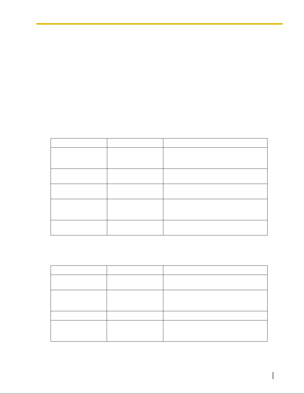
The information displayed is as follows, in order from left to right:
Area Values Description
Software Mode Initial Mode
Batch Mode xxxx
Interactive Mode
Firmware Version Ver x.x.x xxxxxxxxxxxx
(e.g., Ver 1.0.0
Y591AA030519)
See 1.2 Software Modes.
In Batch Mode, the current system data file
name is shown in place of “xxxx”.
Displays the version number of the PBX
software. The numbers following are the ROM
version and the date of creation.
PBX Model Code BX, CE, NE, etc. Displays the model code assigned to the PBX.
1.4 Access Levels
There are 2 main levels of access to the Maintenance Console software: Installer and User.
Maintenance Console 7
Page 8

1.4 Access Levels
Installer-level users can view and edit all settings, in addition to choosing the options and screens available
to User-level users, through the
5.3 Screen Customize option in the View menu.
It is necessary to enter the Installer-level password to log on to Maintenance Console at Installer level.
However, User level access may or may not require a password, depending on whether one has been set
in Programmer Code Change. (See
5.2 Programmer Code Change)
Access to menu options within Maintenance Console also depends on the current software mode (See 1.2
Software Modes).
The target users for each access level are as follows:
Level Use
User For end users
Installer For dealers or system installers
8 Maintenance Console
Page 9
1.5 Standard Buttons
1.5 Standard Buttons
There are several standard buttons that are displayed on most screens within Maintenance Console, and
perform the same function on each screen.
The standard buttons are as follows:
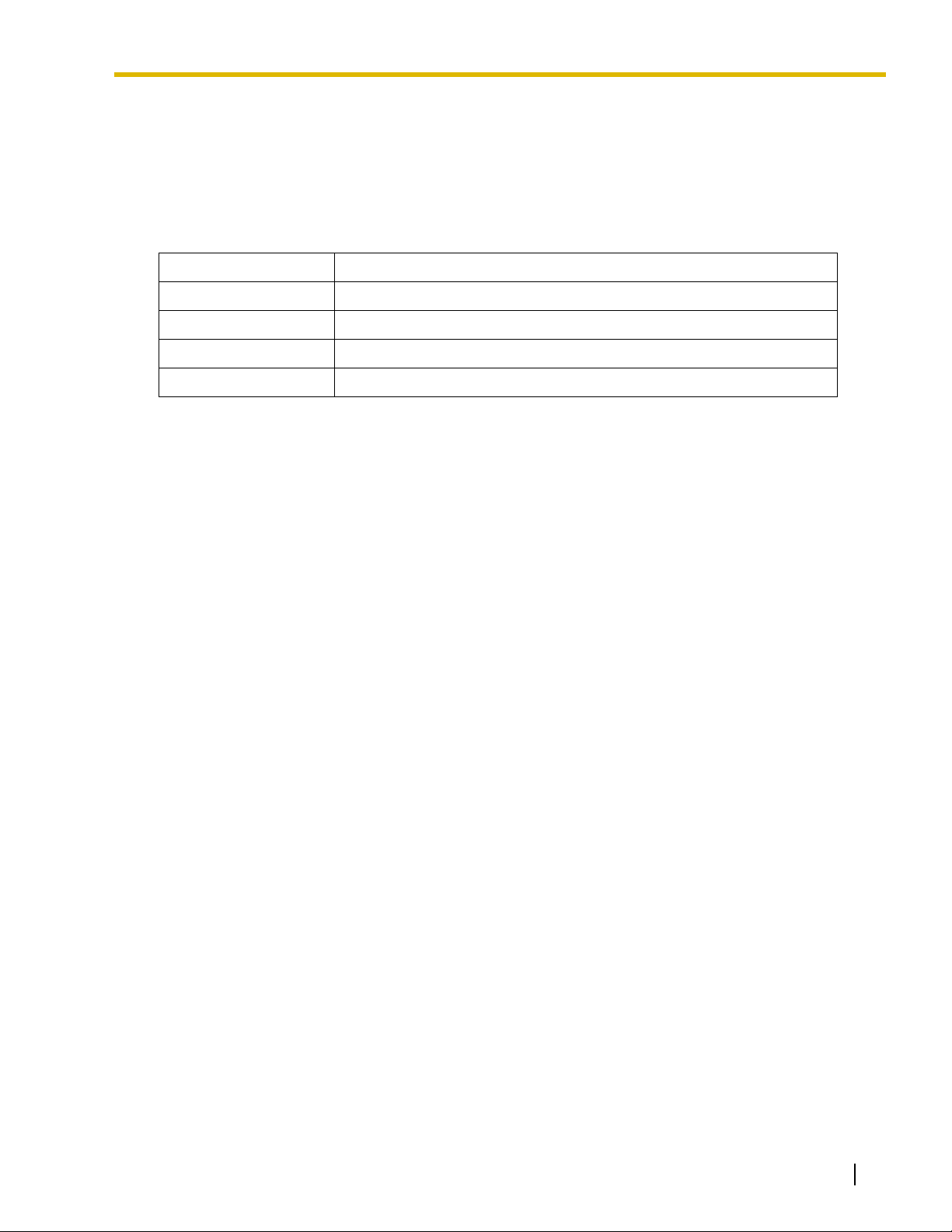
Button Function
OK Implements changes and closes the current screen.
Cancel Abandons changes and returns to the previous screen.
Apply Implements changes and remains on the same screen.
Help Displays the relevant help topic for the current screen.
Maintenance Console 9
Page 10

1.5 Standard Buttons
10 Maintenance Console
Page 11

Section 2
Opening Screen
Every time Maintenance Console is started, a dialog box will
appear.
2.1 Software Modes
Every time Maintenance Console is started, a dialog box will appear. From here, you can enter any of the 3
available software modes.
To start Maintenance Console in Initial mode
1. Enter the relevant programmer code (User or Installer level).
2. Click OK.
Maintenance Console will start.
To start Maintenance Console in Batch mode
1. Enter the relevant programmer code (User or Installer level).
2. Click OK.
Maintenance Console will start.
3. Select an option from the File menu.
• Select New to create a new system data file.
• Select Open to open an existing system data file.
To start Maintenance Console in Interactive mode
1. Enter the relevant programmer code (User or Installer level).
2. Select the Connect to PBX check box.
Connection options will be displayed.
• To use a previously saved profile, select the Use profile check box. When no profiles have been
saved, this check box is not available. Select the desired profile from the list.
3. In Enter System Password, enter the password used to log on to the PBX.
If the system password for the PBX has been stored with the profile, it will be entered automatically.
4. Select the method of connecting to the PBX.
5. If necessary, click the Setup button to modify connection parameters. See the tables below for more
details.
This option is not available when a profile has been selected.
Maintenance Console 11
Page 12

2.1 Software Modes
6. Click OK.
•The OK button is only available when a valid system password has been entered.
Maintenance Console will start, and automatically connect to the PBX. If this is the first time that
Maintenance Console has connected to the PBX, and the date and time of the PBX have not yet been
set, the Quick Setup wizard will run. For more details, see
Connection parameters for RS-232C
Parameter Values Explanation
Por t COMx Specify the number of the COM port assigned
Baud Rate (bps) 9600 Displays the speed of data transmission. This
Word Length 8 bits Displays the number of bits in a word. This
Stop Bit 1 bit Displays the length of the stop, used to identify
6.2 Quick Setup.
to the PC's RS-232C interface. Only available
COM ports will be displayed.
value cannot be changed.
value cannot be changed.
the end of a transmitted group of bits. This
value cannot be changed.
Parity Bit None Displays the kind of parity error-checking used.
This value cannot be changed.
Connection parameters for Modem
Parameter Values Explanation
Dial Number 0-9, *, #, "-" (hyphen)
and "," (comma)
Dial Type Auto (Tone), Auto
(Pulse), Manual
Telephone number to be dialed to access the
PBX.
Outgoing dialing method. If "Manual" is
selected, a telephone must be connected in
parallel to dial.
Comment – Enter a comment to help to identify this profile.
Por t COMx Specify the number of the COM port assigned
to the PC's modem interface. Only available
COM ports will be displayed.
Baud Rate (bps) 1200, 2400, 4800, 9600,
Specify the speed of data transmission.
19200, 38400, 57600,
115200
Flow Control None, Hardware Specify whether the rate of data transfer is
managed by hardware or not.
Modem Initialize Default, Custom Specifies the command used to initialize the
12 Maintenance Console
modem. If "Custom" is selected, enter the
initialize string in the text box. Refer to your
modem's instruction manual for more details.
Page 13

2.1 Software Modes
Parameter Values Explanation
Initialize – Click to send the specified initialize string to the
modem.
Maintenance Console 13
Page 14

2.1 Software Modes
14 Maintenance Console
Page 15

Section 3
This section explains the File menu, which lets you work with
system data files, and view programming items.
3.1 New
Creates a new system data file, used to program the PBX in Batch mode. All settings are in their initial or
default state.
To upload the file created here to the PBX, see 3.6 File Transfer PC to PBX.
Note
Since selecting this option creates an empty system data file, uploading this file to the PBX will
overwrite all previous settings. Use with care.
File
To create a new system data file
•From the File menu, select New.
If a system data file is already open, a window will be displayed to save the current file.
•Click Yes to save the current system data and create a new file.
If the current system data has not previously been saved, the Save As dialog box will be displayed.
See
3.5 Save As for more information.
•Click No to discard the current system data and create a new file.
•Click Cancel to return to the current system data without creating a new file.
3.2 Open
Opens a system data file previously saved on the PC, and enters Batch mode.
To upload a file modified here to the PBX, see 3.6 File Transfer PC to PBX.
To open a system data file
1. From the File menu, select Open.
2. Navigate to the folder containing the system data file you want to open.
3. Select the file.
4. Click Open.
• If the file is not supported by the PBX (e.g., a system data file from an incompatible PBX), it will not be
opened, and a warning message will be displayed. The only files that can be opened are files that were
created by KX-TE Maintenance Console.
Maintenance Console 15
Page 16

3.3 Close
•Click OK to return to the main screen.
3.3 Close
Closes the system data file that is currently being modified in Batch mode, and returns to Initial mode.
To close a system data file
• From the File menu, select Close.
If the system data file has not been saved, a confirmation message will be displayed, giving you the option
to save the file.
•Click Yes to save the file.
•Click No to abandon the changes.
•Click Cancel to return to the previous screen.
3.4 Save
Overwrites the previously saved system data file with the system data currently being modified in Batch
mode.
To upload a file saved here to the PBX, see 3.6 File Transfer PC to PBX.
To save a system data file
• From the File menu, select Save.
If the data has never been saved, the Save As dialog box will be displayed. (See 3.5 Save As.)
3.5 Save As
Saves the system data file being modified in Batch mode with the name chosen by the user.
To upload a file saved here to the PBX, see 3.6 File Transfer PC to PBX.
To save a system data file with a new name
1. From the File menu, select Save As.
2. Navigate to the folder in which you want to save the file.
3. Enter a file name, or select a file to overwrite.
4. Click Save.
If choosing to overwrite another file, a warning message will be displayed. Click Yes to overwrite, or No to
return to the previous screen.
3.6 File Transfer PC to PBX
Restores or uploads previously saved system data to the PBX.
Files that can be transferred with this option are those that were saved using 3.4 Save, 3.5 Save As, or 3.7
File Transfer PBX to PC.
16 Maintenance Console
Page 17

3.7 File Transfer PBX to PC
This option is intended for use when the data stored in the PBX has been lost due to system crash or other
reason, or large-scale edits have been made to the data in Batch mode. Choosing this option will overwrite
any previous settings in the PBX. Use with care.
To transfer system data to the PBX
1. From the File menu, select File Transfer PC to PBX.
2. Navigate to the folder containing the system data file you want to open.
3. Select the file.
4. Click Open.
• If the data contained within the file is not suitable for the PBX, a message will be displayed and the
display will return to the main screen.
The system data file will be transferred to the PBX. A progress indicator displays the current progress.
Once started, the operation cannot be cancelled. When complete, a message will be displayed.
5. Click OK.
3.7 File Transfer PBX to PC
Creates a backup file containing all PBX system data on the PC. Once saved, this file can be edited in Batch
mode using
3.2 Open, if required.
To backup system data to the PC
1. From the File menu, select File Transfer PBX to PC.
2. Navigate to the folder in which you want to save the file.
3. Enter a file name, or select a file to overwrite.
4. Click Save.
The system data will be transferred to the PC. A progress indicator displays the current progress.
• To cancel the operation, click Cancel at any time.
When complete, a message will be displayed.
5. Click OK.
3.8 Program List
Displays a searchable list of PT programming numbers [XXX], feature numbers (XX...), and personal
programming [PT Personal]. Allows direct access to the relevant screen within Maintenance Console.
To view programming topics
1. From the File menu, select Program List.
A list of all PT programming numbers, feature numbers and personal programming is displayed in
numerical order.
• Click the No. or Title cell to reorder the list.
• Enter a text string in the Keyword box and click Search to display all matching programming
topics.
• Double-click a specific programming title in either of the lists, or click it and then click Jump, to go
directly to the relevant Maintenance Console screen.
Maintenance Console 17
Page 18

3.9 Print
2. Click Close to close the window.
3.9 Print
Prints the system data contained in the currently active screen.
The system data in each screen is printed according to that screen's preset output format.
To print the active screen data
1. From the File menu, select Print.
2. From the drop-down list, select the desired printer.
3. Click Print.
3.10 Print ALL
Prints all system data, except for that contained in the 7.1.1 Date & Time [1-1] screen.
The total number of pages to be printed is displayed at the bottom of the window.
The system data in each screen is printed according to that screen's preset output format.
To print system data from multiple screens
1. From the File menu, select Print ALL.
A list of the system data screens will be displayed in outline view.
By default, all system data is selected for printing.
• Click the plus sign to expand an item.
• Click the minus sign to collapse a previously expanded item.
• Clear the check boxes of screens you do not want to print.
2. Click Print.
3. From the drop-down list, select the desired printer.
4. Click Print.
3.11 Exit
Closes Maintenance Console.
To exit Maintenance Console
1. From the File menu, select Exit.
A confirmation message will be displayed.
2. Click Yes.
• In Batch mode, if the system data file being modified has not been saved, a message will be
displayed, giving you the option to save the file.
•Click Yes to save the file.
•Click No to abandon the changes.
•Click Cancel to return to the previous screen.
18 Maintenance Console
Page 19

3.11 Exit
• In Interactive mode, if the system data being modified has not been transmitted to the PBX, a
message will be displayed, giving you the option to transmit the data.
•Click Yes to transmit the data.
•Click No to abandon the changes.
•Click Cancel to return to the previous screen.
The software will exit.
Maintenance Console 19
Page 20

3.11 Exit
20 Maintenance Console
Page 21

Section 4
Connect
This section describes the Connect menu, which offers
options for connecting a PC to the PBX.
4.1 Connect
Connects the PC to the PBX.
There are 3 ways to connect the PC to the PBX: RS-232C, USB, and modem.
This option allows direct entry of connection parameters, for cases where the PC is used to connect to one
or just a few PBXs, and an individual profile for each PBX is not necessary. If you connect to multiple PBXs
and would prefer to choose from among pre-saved profiles instead, see
about creating profiles.
When connecting to the PBX for the first time, the Quick Setup utility will run automatically. For more details,
see
6.2 Quick Setup.
4.3 Profile Setup for more details
To connect to the PBX by RS-232C
1. From the Connect menu, select Connect.
The Connect to PBX window will be displayed.
2. Select a connection option.
• Select the Use profile check box if you want to use a pre-saved profile. This option is only available
when one or more profiles have been previously stored.
a. Select the profile to use from the drop-down list.
b. If the system password for the PBX has not been stored with the profile, enter it.
If the system password has been stored with the selected profile, it does not need to be
entered. The password box will become unavailable.
• Select the RS-232C radio button if you want to enter parameters manually.
(a) Enter the system password for the PBX.
(b) Click Setup.
(c) Specify the COM port as required. For more details, see the table below.
(d) Click OK.
3. Click OK.
The parameters are as follows:
Maintenance Console 21
Page 22

4.1 Connect
Parameter Values Explanation
Por t COMx Specify the number of the COM port assigned
to the PC's RS-232C interface. Only available
COM ports will be displayed.
Baud Rate (bps) 9600 Displays the speed of data transmission. This
value cannot be changed.
Word Length 8 bits Displays the number of bits in a word. This
value cannot be changed.
Stop Bit 1 bit Displays the length of the stop, used to identify
the end of a transmitted group of bits. This
value cannot be changed.
Parity Bit None Displays the kind of parity error-checking used.
This value cannot be changed.
When connecting the KX-TE Maintenance Console to the PBX using an RS-232C cable, assign the
following values to the Serial Interface (RS-232C) port of the PBX:
Baud Rate: 9600 bps
Word Length: 8 bit
Parity Bit: None
Stop Bit: 1 bit
To connect to the PBX by USB
1. From the Connect menu, select Connect.
The Connect to PBX window will be displayed.
2. Select a connection option.
• Select the Use profile check box if you want to use a pre-saved profile.
a. Select the profile to use from the drop-down list.
b. If the system password for the PBX has not been stored with the profile, enter it.
If the system password has been stored with the selected profile, it does not need to be
entered. The password box will become unavailable.
• Select the USB radio button if you do not want to use a profile.
• Enter the system password for the PBX.
3. Click OK.
To connect to the PBX by Modem
1. From the Connect menu, select Connect.
The Connect to PBX window will be displayed.
2. Select a connection option.
• Select the Use profile check box if you want to use a pre-saved profile.
a. Select the profile to use from the drop-down list.
b. If the system password for the PBX has not been stored with the profile, enter it.
If the system password has been stored with the selected profile, it does not need to be
entered. The password box will become unavailable.
• Select the Modem radio button if you want to enter parameters manually.
22 Maintenance Console
Page 23

(a) Enter the system password for the PBX.
(b) Click Setup.
(c) Modify the connection parameters as required. For more details, see the table below.
(d) Click OK.
3. Click OK.
The parameters are as follows:
Parameter Values Explanation
4.2 Disconnect
Dial Number 0-9, *, #, "-" (hyphen)
and "," (comma)
Dial Type Auto (Tone), Auto
(Pulse), Manual
Comment – Enter a comment to help to identify this profile.
Por t COMx Specify the number of the COM port assigned
Baud Rate (bps) 1200, 2400, 4800, 9600,
19200, 38400, 57600,
115200
Flow Control None, Hardware Specify whether the rate of data transfer is
Modem Initialize Default, Custom Specifies the command used to initialize the
Initialize – Click to send the specified initialize string to the
Telephone number to be dialed to access the
PBX.
Outgoing dialing method. If "Manual" is
selected, a telephone must be connected in
parallel to dial.
to the PC's modem interface. Only available
COM ports will be displayed.
Specify the speed of data transmission.
managed by hardware or not.
modem. If "Custom" is selected, enter the
initialize string in the text box. Refer to your
modem's instruction manual for more details.
modem.
4.2 Disconnect
Disconnects the PC from the PBX. Data transmission ends, and Maintenance Console returns to Initial
mode.
To disconnect
•From the Connect menu, select Disconnect.
If there is data that has been edited but not yet sent to the PBX, a confirmation window will be displayed.
•Click Yes to send the data to the PBX.
•Click No to discard the data.
Maintenance Console 23
Page 24

4.3 Profile Setup
4.3 Profile Setup
Profiles are useful when one PC is used to connect to multiple PBXs. Rather than manually adjusting the
connection parameters each time a different PBX is accessed, it is possible to store the connection
parameters for several PBXs. Then, when you wish to connect to a specific PBX, you can simply choose
that PBX's profile from
The functions of the buttons on this screen are as follows:
Button Function
New Opens the Profile Editor window to create a new profile. See 4.4 Profile
Edit When an existing profile is selected, opens the Profile Editor window to
Delete When an existing profile is selected, deletes that profile. A confirmation
Close Closes the current window.
4.1 Connect.
Editor.
modify the parameters of that profile. See
message will be displayed.
4.4 Profile Editor.
4.4 Profile Editor
Allows the creation and editing of profiles of parameters required to connect the PC to the PBX by RS-232C,
USB or modem.
Note
When a profile is edited and saved with a new name, the original profile is not deleted.
The parameters are as follows:
Parameter Description
Profile Name Enter a name used to identify this set of PBX connection parameters.
This name must not be the same as another profile name.
System Password Enter the password to log on to the target PBX, if required.
Default Select the default connection method.
The functions of the buttons on this screen are as follows:
Button Function
Save Saves the current profile information.
Cancel Closes the current screen without saving the profile information.
To create or edit a profile
1. From the Connect menu, select Profile Setup.
The Profile Setup window (4.3 Profile Setup) will be displayed.
24 Maintenance Console
Page 25
4.4 Profile Editor
2. Click New or Edit.
The Profile Editor window will be displayed.
3. Enter a name for this profile.
4. Enter the system password used to connect to the PBX.
5. Select the default connection method.
6. Enter the detailed connection method parameters as required. See the tables below for more
information.
It is possible to select connection methods other than the default method when connecting to the PBX
using this profile. For this reason, you can choose to input parameters for both RS-232C and modem
connection. Click the tabs to view the parameters for each type of connection.
7. Click Save.
Connection parameters for RS-232C
The parameters are as follows:
Parameter Values Explanation
Por t COMx Specify the number of the COM port assigned
to the PC's RS-232C interface. Only available
COM ports will be displayed.
Baud Rate (bps) 9600 Displays the speed of data transmission. This
value cannot be changed.
Word Length 8 bits Displays the number of bits in a word. This
value cannot be changed.
Stop Bit 1 bit Displays the length of the stop, used to identify
the end of a transmitted group of bits. This
value cannot be changed.
Parity Bit None Displays the kind of parity error-checking used.
This value cannot be changed.
Connection parameters for Modem
The parameters are as follows:
Parameter Values Explanation
Dial Number 0-9, *, #, "-" (hyphen)
and "," (comma)
Dial Type Auto (Tone), Auto
(Pulse), Manual
Comment – Enter a comment to help to identify this profile.
Telephone number to be dialed to access the
PBX.
Outgoing dialing method. If "Manual" is
selected, a telephone must be connected in
parallel to dial.
Por t COMx Specify the number of the COM port assigned
to the PC's modem interface. Only available
COM ports will be displayed.
Maintenance Console 25
Page 26

4.4 Profile Editor
Parameter Values Explanation
Baud Rate (bps) 1200, 2400, 4800, 9600,
Specify the speed of data transmission.
19200, 38400, 57600,
115200
Flow Control None, Hardware Specify whether the rate of data transfer is
managed by hardware or not.
Modem Initialize Default, Custom Specifies the command used to initialize the
modem. If "Custom" is selected, enter the
initialize string in the text box. Refer to your
modem's instruction manual for more details.
Initialize – Click to send the specified initialize string to the
modem.
26 Maintenance Console
Page 27

Section 5
This section describes the View menu, which allows you to
customize the operation of Maintenance Console.
5.1 Tool Bar
Selects whether the tool bar, which provides icons allowing easy access to commonly used functions, is
displayed or not.
A check mark before this menu option means that the tool bar is set to be displayed.
To change the display status of the tool bar
•From the View menu, select Tool Bar.
View
5.2 Programmer Code Change
Allows you to change the codes used to log on to Maintenance Console at startup.
Users logged on at Installer level may change both Installer level and User level codes. However, users
logged on at User level can only change the User level code.
Programmer codes can contain any characters.
To change the User level code
1. From the View menu, point to Programmer Code Change, and then click User Level.
The Programmer Code Change screen will be displayed.
2. Enter the desired new code.
3. Re-enter the same code for verification.
If the entered codes do not match, an error message will be displayed.
•Click OK to return to step 2 above.
4. Click OK.
To change the Installer level code
1. From the View menu, point to Programmer Code Change, and then click Installer Level.
The Programmer Code Change screen will be displayed.
2. Enter the desired new code.
3. Re-enter the same code for verification.
Maintenance Console 27
Page 28

5.3 Screen Customize
If the entered codes do not match, an error message will be displayed.
•Click OK to return to step 2 above.
4. Click OK.
5.3 Screen Customize
Allows you to specify which system data setting screens and menu options can be accessed when logged
in to Maintenance Console at User level.
This option is only available at Installer level.
To customize the displayed options
1. From the View menu, select Screen Customize.
A list of the system data screens will be displayed in outline view.
• Click the desired tab to view system data setting screens or menu options.
• Click the plus sign to expand an item.
• Click the minus sign to collapse a previously expanded item.
• Clear the check boxes of screens you do not want to make available in User level.
2. Click OK.
5.4 System Data Setting Menu
Provides an alternative method of opening system data screens.
This option is only displayed in Batch and Interactive modes.
•From the View menu, point to System Data Setting Menu, point to the desired parent item, and
then click the desired child item to open the relevant screen.
28 Maintenance Console
Page 29

Section 6
This section describes the Utility menu, which contains
options for performing system maintenance on the PBX.
6.1 Firmware Upgrade
Allows installation of upgrades to the system software stored within the PBX. Only install upgrades provided
by certified Panasonic dealers.
To upgrade system software
1. From the Utility menu, select Firmware Upgrade.
The Firmware Upgrade screen will be displayed.
2. Click Select.
The Open dialog box will be displayed.
3. Navigate to the folder containing the system software file you want to install.
4. Select the file.
5. Click Open.
• If the selected file is not a recognized ROM file, an error message will be displayed.
•Click OK to return to step 2.
• If the selected file is an older ROM version than the one currently installed to the PBX, a warning
message will be displayed.
• To accept the older ROM version, click Yes. Installing an older ROM is not recommended, as
it may cause problems during system data conversion.
• To not use the older ROM version, click No.
• If the selected file is a ROM version newer than that of the current Maintenance Console software,
a warning message will be displayed, as it cannot be supported by Maintenance Console.
Information about the version of both the current system software and the selected file will be displayed.
6. Confirm that the selected file is the version that you intend to install to the PBX.
7. Click Start.
A confirmation message will be displayed.
8. Click Yes.
The system software will be upgraded in 3 steps. The progress bar shows how much of each process
has been completed.
When the upgrade is complete, a message will be displayed.
• If there was a communication error during the upgrade, a message will be displayed.
Utility
Maintenance Console 29
Page 30

6.2 Quick Setup
1. Check the listed items.
2. Click Retry to try the upgrade process again.
• If the PC freezes or loses power during one of the upgrade steps listed below, restart
Maintenance Console, reconnect to the PBX, and follow the instructions below.
• While downloading system data from the PBX
The Firmware Upgrade screen will be displayed automatically. Reselect the system
software file and perform the upgrade again.
• While writing the new software to the PBX
The PBX will be unable to start properly. The Firmware Upgrade screen will be
displayed automatically. Reselect the system software file and perform the upgrade
again.
• While restoring system data to the PBX
The Firmware Upgrade process will be automatically restarted from this step, and
system data will be restored to the PBX.
6.2 Quick Setup
Allows basic settings of the PBX to be modified easily.
This option can be accessed in either of 2 ways:
• Automatically when connecting to the PBX for the first time or after the PBX data has been cleared.
• Manually, by selecting Quick Setup from the Utility menu.
This option only runs automatically when the following conditions are met:
• The user is logged on to Maintenance Console using the Installer level programmer code.
• The date and time of the PBX have not yet been set.
• The model code of Maintenance Console and PBX match.
• The user has selected to connect Maintenance Console to the PBX in Interactive mode.
It can be run manually when the following condition is met:
• Maintenance Console is connected to the PBX in Interactive mode.
When the Quick Setup wizard is started manually, it is possible to cancel the wizard at any point by clicking
the Cancel button. No changes will be made to the PBX. However, the Cancel button is not available when
Quick Setup runs automatically upon connection to the PBX. In addition, when Quick Setup runs, it shows
only default data for all programmable parameters. Any existing settings are not shown, and will be
overwritten, so run Quick Setup manually only when necessary.
Using Quick Setup, the following basic parameters can be programmed as desired:
• The date and time. The PBX uses the date and time set to the PC. (→ 7.1.1 Date & Time [1-1])
• The system password. (→ 7.1.2 Main [1-2])
• The operator extension number. (→ 2.2.4 Operator/Manager Features in the Feature Guide)
• Automatic Configuration for CO Line Type (DTMF/Pulse). (→ 2.3.5 Automatic Configuration for
Outside (CO) Line Type in the Feature Guide)
• Extension numbers and names. (→ 1.5.1.1 Intercom Call in the Feature Guide)
• Ringing assignment for each outside line (either all extensions, or a specific extension). (→ 1.1.3.2
Outside (CO) Line Ringing Selection in the Feature Guide)
To set up basic items for the PBX
1. From the Utility menu, click Quick Setup.
30 Maintenance Console
Page 31

6.3 System Reset
• The Automatic Configuration for CO Line Type screen will be displayed.
1. If you do not want to automatically configure outside (CO) line types, deselect the check box.
2. Click Next.
The Step 2 screen will be displayed.
2. Select the desired settings from the displayed boxes.
• Select the jack number you wish to register as the operator extension, or "Disable".
• If you do not want to configure the operator extension and feature numbers, deselect the check
box.
3. Click Next.
The Step 3 screen will be displayed.
4. Enter the desired extension number and name (if required) for each jack to configure in the table.
• If you do not want to configure extension numbers and names, deselect the check box.
5. Click Next.
The Step 4 screen will be displayed.
6. For each outside (CO) line, select the ringing assignment.
• Select "All extensions" to have all extensions ring for calls from that outside (CO) line.
• Select a jack number to have only that extension ring for calls from that outside (CO) line.
• If you do not want to configure a particular outside (CO) line, deselect the check box beside the
name of that line.
7. Click Next.
The Step 5 screen will be displayed.
8. Enter the date and time.
• By default, the date and time of the PC are shown in these boxes.
9. Enter the desired system password, to be used to log on to the PBX.
• The password must be from 4 to 7 digits long.
• You must enter the same password 2 times, for confirmation.
• Be sure to make a note of the password entered here, as it will be required to log on to the PBX.
10. Click Finish.
• The data items set in steps 1 to 5 will be transmitted to the PBX.
A completion message will be displayed.
11. Click OK.
6.3 System Reset
Resets the PBX.
There are 2 levels of reset:
• Normal: The PBX will be reset.
• Default: The PBX will be reset, and programming settings returned to their default values.
6.3.1 Normal
Resets the PBX.
Maintenance Console 31
Page 32

6.4 System Data Clear
To reset the PBX
1. From the Utility menu, point to System Reset, and then select Normal.
A confirmation message will be displayed.
2. Click Yes.
The PBX will be disconnected from Maintenance Console, and will reset.
6.3.2 Default
Resets the PBX, and returns programming settings to their default values.
This option clears all settings within the PBX. Use this feature only when necessary, as all setting data within
the PBX will be lost. If required, take a backup of system data in advance, using
To clear all settings and reset the PBX
1. From the Utility menu, point to System Reset, and then select Default.
A confirmation message will be displayed.
2. Click Yes.
The PBX will be disconnected from Maintenance Console, and will reset.
3.7 File Transfer PBX to PC.
6.4 System Data Clear
Initializes PBX system data and programming settings. Use this feature only when necessary, as all system
and setting data within the PBX will be lost. If required, take a backup of system data in advance, using
File Transfer PBX to PC.
To initialize PBX system data
1. From the Utility menu, select System Data Clear.
The System Data Clear window will be displayed.
2. Select the system data to delete.
•Click ALL to delete all system data.
•Click Custom to select specific data to delete.
• Select the appropriate check boxes.
3. Click OK.
A completion message will be displayed.
4. Click OK.
6.5 DISA OGM Clear
Initializes the outgoing messages (OGMs) for the DISA feature.
OGMs on both the preinstalled OGM card and the optional OGM card (if present) will be deleted.
3.7
To clear all OGMs
1. From the Utility menu, select DISA OGM Clear.
A confirmation message will be displayed.
32 Maintenance Console
Page 33

6.6 BV Card Initialization
2. Click Yes.
A completion message will be displayed.
3. Click Yes.
6.6 BV Card Initialization
Initializes the optional BV card installed in the PBX, clearing all messages stored using the BV feature. This
option requires that a BV card be installed in the PBX.
To initialize the BV card
1. From the Utility menu, select BV Card Initialization.
A confirmation message will be displayed.
2. Click OK.
A completion message will be displayed.
3. Click Yes.
Maintenance Console 33
Page 34

6.6 BV Card Initialization
34 Maintenance Console
Page 35

Section 7
System Data Setting
Maintenance Console 35
Page 36

7.1 System [1]
7.1 System [1]
7.1.1 Date & Time [1-1]
The date and time of the PBX can be programmed. The date and time will be shown on the displays of
proprietary telephones (PTs) and Station Message Detail Recording (SMDR).
Date
Indicates the current date of the PBX. A calendar program window appears when you type or select the part
of the date you want to change in the Date box. The day of the week is changed automatically to reflect the
assigned date.
Default
04.Jan.1 Thu
Value Range
Year: 2000–2099
Month: 01–12
Day: 01–31
Week: Monday, Tuesday, Wednesday, Thursday, Friday, Saturday, Sunday
Feature Guide References
1.19.1 Station Message Detail Recording (SMDR)
Date & Time [000]
Time
Indicates the current time of the PBX. Type or select the part of the time you want to change in the Time
box if necessary.
Default
AM12:00
Value Range
AM12:00–PM11:59
Feature Guide References
1.19.1 Station Message Detail Recording (SMDR)
Date & Time [000]
36 Maintenance Console
Page 37

7.1.2 Main [1-2]
Various system settings can be programmed.
System Password
Specifies the system password used to access system programming in interactive mode.
Default
1234
Value Range
4–7 digits (consisting of 0–9)
Feature Guide References
2.3.1 PC Programming
2.3.2 PT Programming
System Password [002]
7.1 System [1]
Operator
Selects the extension jack number to be designated as the operator.
Default
Jack 01
Value Range
Disable, Jack 01–24
Feature Guide References
2.2.4 Operator/Manager Features
Operator Assignment [008]
Time—Time Display
Selects the time format shown on the displays of proprietary telephones (PTs) while on-hook. The Date &
Time, Time Service, Station Message Detail Recording (SMDR) and Timed Reminder features use 12-hour
format even if 24-hour format is assigned in this program.
Default
12 h
Value Range
12 h, 24 h
Feature Guide References
LCD Time Display [010]
Maintenance Console 37
Page 38

7.1 System [1]
Time—Automatic Time Adjustment
Enables the PBX to adjust its clock every day according to the time information included with the first Caller
ID call after 3:05 A.M.
Default
On
Value Range
On (checked), Off (unchecked)
Feature Guide References
2.3.3 Automatic Time Adjustment
Automatic Time Adjustment [152]
Music on Hold
Selects the audio source for Music on Hold and Background Music (BGM).
Default
External
Value Range
External, Tone
Feature Guide References
1.11.4 Music on Hold
1.14.4 Background Music (BGM)
Music on Hold [111]
Voice Mail
Selects the method of Voice Mail Integration.
Default
Disable
• DTMF Integration (VM Port): Off
• APT Integration (VM1 APT Port/VM2 APT Port): Disable
Value Range
Disable, DTMF Integration, APT Integration
Disable: Disables both Inband (DTMF) and APT Integration.
DTMF Integration: Enables Inband (DTMF) Integration.
The following extension jack number(s) connected to a Panasonic VPS can be specified as the voice mail
ports:
• VM Port: Jack 07, Jack 08, Jack 15, Jack 16
38 Maintenance Console
Page 39

7.1 System [1]
APT Integration: Enables APT Integration.
The following extension jack number(s) connected to a Panasonic VPS can be specified as the voice mail
ports:
• VM1 APT Port: Disable, Jack 07, Jack 07 & 08
• VM2 APT Port: Disable, Jack 15, Jack 15 & 16
Feature Guide References
1.18.1 Voice Mail APT Integration
1.18.2 Voice Mail Inband (DTMF) Integration
DTMF Integration Port [102]
DTMF Integration [103]
VM 1 APT Port [130]
VM 2 APT Port [131]
Maintenance Console 39
Page 40

7.1 System [1]
7.1.3 Numbering Plan [1-3]
Extension numbers and extension names can be programmed for each extension.
Jack
Indicates the jack number (reference only). Sort in either ascending or descending order by clicking the Jack
header.
Value Range
01–24
Ext. no.
Selects an extension number for each extension. Each extension must have a unique extension number.
Sort in either ascending or descending order by clicking the Ext. no. header.
Default
Jack 01–24 = Ext. no. 101–124 (e.g., Jack 01: Ext. no. 101, Jack 02: Ext. no. 102)
Value Range
100–199
Feature Guide References
1.5.1.1 Intercom Call
2.3.4 Feature Numbering
Extension Number [009]
Name
Specifies the names of extensions, to be shown on the display of proprietary telephones (PTs) during
intercom calls. Sort in either ascending or descending order by clicking the Name header.
Default
All jacks: — (Not stored)
Value Range
Max. 10 characters
Feature Guide References
1.5.1.1 Intercom Call
Extension Name [604]
40 Maintenance Console
Page 41

7.1.4 Time Service [1-4]
A specific time service mode (day, night, or lunch) can be selected for operation depending on the time of
the day. The time service mode can be switched either automatically or manually. When Manual is selected
Time Service Switching Mode list, the current time service mode can be selected from the Current
in the
Mode list. Manual switching is possible only from an extension assigned as the operator or manager
extension. When Automatic is selected, the current time service mode will switch to another time service
mode at the time preprogrammed on the
time service modes are distinguished in the table with different colors. To change the time in the Time Table,
click Time Setting. To change the color settings of each time service mode, click Day, Night, or Lunch.
Time Service Switching Mode
Selects whether the time service mode is switched between day, lunch, and night manually or automatically.
Default
Manual
Value Range
Manual, Automatic
7.1.5 Time Service [1-4] Time Setting screen. In addition, the
7.1 System [1]
Programming Guide References
7.1.5 Time Service [1-4] Time Setting
Feature Guide References
2.2.3 Time Service
Time Service Switching Mode [006]
Current Mode
This program is available only when Manual is selected in Time Service Switching Mode on this screen.
Selects the current time service mode manually.
Default
Day
Value Range
Day, Night, Lunch
Feature Guide References
2.2.3 Time Service
2.2.4 Operator/Manager Features
User Manual References
2.1.2 Switching the Time Service Mode (Time Service)
Maintenance Console 41
Page 42

7.1 System [1]
7.1.5 Time Service [1-4] Time Setting
These settings are only available when Automatic is selected in Time Service Switching Mode on the
7.1.4 Time Service [1-4] screen.
Time Tables (containing day, lunch, and night start times and lunch end time) can be programmed for each
day of the week.
Day
Enables the setting of the Day start time. If enabled (checked), the start time can be specified.
Default
Every day of the week: On (AM09:00)
Value Range
On (AM12:00–PM11:59), Off
Programming Guide References
7.1.4 Time Service [1-4]
Feature Guide References
2.2.3 Time Service
Time Service Start Time [007]
Night
Enables the setting of the Night start time. If enabled (checked), the start time can be specified.
Default
Every day of the week: On (PM05:00)
Value Range
On (AM12:00–PM11:59), Off
Programming Guide References
7.1.4 Time Service [1-4]
Feature Guide References
2.2.3 Time Service
Time Service Start Time [007]
Lunch Start
Enables the setting of the Lunch start time. If enabled (checked), the start time can be specified. Lunch
mode overrides Day or Night mode.
Default
Every day of the week: Off (Not stored)
42 Maintenance Console
Page 43

Value Range
On (AM12:00–PM11:59), Off
Programming Guide References
7.1.4 Time Service [1-4]
Feature Guide References
2.2.3 Time Service
Time Service Start Time [007]
Lunch End
Enables the setting of the Lunch end time. If enabled (checked), the end time can be specified.
Default
Every day of the week: Off (Not stored)
Value Range
On (AM12:00–PM11:59), Off
7.1 System [1]
Programming Guide References
7.1.4 Time Service [1-4]
Feature Guide References
2.2.3 Time Service
Time Service Start Time [007]
Maintenance Console 43
Page 44

7.1 System [1]
7.1.6 Account Codes [1-5]
A maximum of 50 account codes can be programmed and used to identify outgoing outside (CO) line calls
for accounting and billing purposes.
Account Code
Specifies the account codes that must be entered when Verify-All (an account code is required to make an
outside (CO) line call) or Verify-Toll (an account code is required to override Toll Restriction [TRS]
temporarily) is selected in
Default
All codes: — (Not stored)
Value Range
4 digits (consisting of 0–9)
Programming Guide References
7.2.1 Main [2-1]
Account Code Mode on the 7.2.1 Main [2-1] screen.
Feature Guide References
1.5.2.3 Account Code Entry
1.8.2 Toll Restriction (TRS) Override by Account Code
Account Code [310]
44 Maintenance Console
Page 45

7.1.7 Timers [1-6]
Various system timers and counters can be programmed.
Automatic Redial—Repeat Counter
Selects the number of times automatic redialing is attempted before being cancelled.
Default
0
Value Range
0, 3, 10, 15
Automatic Redial—Interval Time
Selects the length of time between the repeated automatic redialing.
Default
40 s
7.1 System [1]
Value Range
40 s, 60 s
Recall Time—Call Hold
Selects the length of time a call on hold waits to be retrieved. If the call on hold is not retrieved within the
time period programmed here, a ring tone will be heard at the extension that put the call on hold. If the
extension is engaged in a call, an alarm tone will be heard.
Default
30 s
Value Range
Disable, 30 s, 1 min, 1.5 min, 2–6 min
Feature Guide References
1.11.1 Call Hold
1.11.2 Call Park
Hold Recall Time [200]
Recall Time—Call Transfer
Selects the length of time a transferred call waits to be answered. If the transfer destination does not answer
the call within the time period programmed here, the call will return to the extension that transferred the call.
Default
30 s
Maintenance Console 45
Page 46

7.1 System [1]
Value Range
15 s, 30 s, 1 min, 2 min
Feature Guide References
1.10.1 Call Transfer
Transfer Recall Time [201]
Start Time—Call Forwarding
Selects the length of time before a call is forwarded when the call is not answered.
Default
15 s
Value Range
5 s, 10 s, 15 s, 20 s
Feature Guide References
1.3.1.2 Call Forwarding (FWD)
Call Forwarding Start Time [202]
Start Time—Hot Line
Selects the length of time until automatic dialing starts after a single line telephone (SLT) user goes off-hook.
Default
3 s
Value Range
0–4 s
Feature Guide References
1.6.1.6 Hot Line
Hot Line Waiting Time [203]
Call Duration—Call Duration Counter Start Time
Selects when the call timer starts, either immediately after an outside (CO) line is seized, or after the end
of dialing. This corresponds to the length of the conversation displayed on the LCD and logged by SMDR.
Default
10 s
Value Range
Immediate, 5 x n (n=1–10) s
Immediate: The call timer starts immediately after an outside (CO) line is seized.
5 x n (n=1–10) s: The call timer starts after the end of dialing.
46 Maintenance Console
Page 47

7.1 System [1]
Feature Guide References
1.19.1 Station Message Detail Recording (SMDR)
Call Duration Counter Start [204]
Call Duration—CO-to-CO Duration Limit
Selects the maximum length of time allowed for a conversation between 2 outside parties using the Call
Forwarding (FWD) to Outside (CO) Line, Call Transfer to Outside (CO) Line, Unattended Conference, or
DISA feature.
Default
10 min
Value Range
1–32 min
Feature Guide References
1.9.8 Outside-to-Outside (CO-to-CO) Line Call Duration
CO-to-CO Line Call Duration [205]
CO Dialing—Dialing Start Time
Selects the minimum length of time that the PBX waits after seizing an outside (CO) line before dialing.
Default
0 ms
Value Range
0 ms, 250 ms, 500 ms, 750 ms, 1000 ms, 1250 ms, 1500 ms
Feature Guide References
1.5.3.3 Outside (CO) Line Access
Dialing Start Time [206]
CO Dialing—No Dial Disconnection
Selects whether or not to disconnect an outside (CO) line when an extension user does not dial anything
within 10 seconds after seizing the outside (CO) line.
Default
Disable
Value Range
Disable (Do not disconnect), Enable (Disconnect)
Feature Guide References
1.8.1 Toll Restriction (TRS)
No Dial Disconnection [211]
Maintenance Console 47
Page 48

7.1 System [1]
CO Dialing—Inter-digit Time
Selects the length of time allowed between digits for an outgoing outside (CO) line call.
Default
10 s
Value Range
5 s, 10 s, 15 s, 20 s
Feature Guide References
1.8.1 Toll Restriction (TRS)
Inter-digit Time [208]
48 Maintenance Console
Page 49

7.1.8 SMDR [1-7]
Station Message Detail Recording (SMDR) automatically records detailed information about incoming and
outgoing calls.
RS-232C Parameters—NL Code
Selects the code appropriate for the PC or printer. If the PC or printer automatically feeds lines with carriage
return, this selection must be set to CR. If not, CR+LF.
Default
CR+LF
Value Range
CR+LF, CR
CR: Carriage Return
LF: Line Feed
Feature Guide References
1.19.1 Station Message Detail Recording (SMDR)
SMDR RS-232C Parameter [800]
7.1 System [1]
RS-232C Parameters—Baud Rate
Selects the transmission speed of data from the PBX to the PC or printer.
Default
9600 bps
Value Range
1200 bps, 2400 bps, 4800 bps, 9600 bps
Feature Guide References
1.19.1 Station Message Detail Recording (SMDR)
SMDR RS-232C Parameter [800]
RS-232C Parameters—Word Length
Selects how many bits compose each character.
Default
8 bits
Value Range
7 bits, 8 bits
Maintenance Console 49
Page 50

7.1 System [1]
Feature Guide References
1.19.1 Station Message Detail Recording (SMDR)
SMDR RS-232C Parameter [800]
RS-232C Parameters—Parity Bit
Selects what type of parity is used to detect errors in the string of bits composing a character.
When the error checking function is not required from the printer, None must be selected in this program.
Default
None
Value Range
None, Mark, Space, Even, Odd
Feature Guide References
1.19.1 Station Message Detail Recording (SMDR)
SMDR RS-232C Parameter [800]
RS-232C Parameters—Stop Bit
Selects the end of a bit string that composes a character.
CAUTION
Do not use the following combinations:
• Parity Bit: Mark, Word Length: 8 bits, Stop Bit: 2 bits
• Parity Bit: Space, Word Length: 8 bits, Stop Bit: 1 bit
• Parity Bit: Space, Word Length: 8 bits, Stop Bit: 2 bits
If any of the above invalid combinations are selected, an error message will be displayed.
Default
1 bit
Value Range
1 bit, 2 bits
Feature Guide References
1.19.1 Station Message Detail Recording (SMDR)
SMDR RS-232C Parameter [800]
SMDR Format—Page Length
Selects the number of lines per page in order to match the paper size being used by the printer.
Default
66 lines
50 Maintenance Console
Page 51

7.1 System [1]
Value Range
4–99 lines
Feature Guide References
1.19.1 Station Message Detail Recording (SMDR)
SMDR Parameter [801]
SMDR Format—Skip Perforation
Selects the number of lines to be skipped at the end of every page in order to match the paper size being
used by the printer.
Default
0 line
Value Range
0–95 lines
Feature Guide References
1.19.1 Station Message Detail Recording (SMDR)
SMDR Parameter [801]
Selection for Printing—Outgoing Call
Selects whether the dialed digits of outgoing outside (CO) line calls are printed.
Default
On
Value Range
On (Print all calls), Off (No printing), Toll (Print toll calls only)
Feature Guide References
1.19.1 Station Message Detail Recording (SMDR)
Incoming/Outgoing Call Selection for Printing [802]
Selection for Printing—Incoming Call
Selects whether the dialed digits of incoming outside (CO) line calls are printed.
Default
On
Value Range
On (Print all calls), Off (No printing)
Feature Guide References
1.19.1 Station Message Detail Recording (SMDR)
Maintenance Console 51
Page 52

7.1 System [1]
Incoming/Outgoing Call Selection for Printing [802]
Selection for Printing—Account Code
Selects whether to print out the account code stored in Account Code on the 7.1.6 Account Codes [1-5]
screen, or just the index of the account code on SMDR. The index of the account code is shown when
Verify-All or Verify-Toll is selected in
Default
CODE
Value Range
CODE, INDEX
Programming Guide References
7.1.6 Account Codes [1-5]
7.2.1 Main [2-1]
Feature Guide References
1.8.2 Toll Restriction (TRS) Override by Account Code
1.19.1 Station Message Detail Recording (SMDR)
SMDR Account Code [805]
Account Code Mode on the 7.2.1 Main [2-1] screen.
Selection for Printing—Secret Number
Selects whether secret dialing numbers are printed with SMDR. Secret dialing numbers are not shown on
the displays of proprietary telephones (PTs), regardless of this setting.
Default
Off
Value Range
On (checked), Off (unchecked)
Feature Guide References
1.19.1 Station Message Detail Recording (SMDR)
Secret Number SMDR Print Suppression [803]
Selection for Printing—Language
Selects the display language used for SMDR.
Default
English
Value Range
English, Spanish
52 Maintenance Console
Page 53

Feature Guide References
1.19.1 Station Message Detail Recording (SMDR)
SMDR Language [806]
7.1 System [1]
Maintenance Console 53
Page 54

7.1 System [1]
7.1.9 Carrier Exception Codes [1-8]
A maximum of 20 Carrier Exception codes can be programmed. The PBX can recognize a user-dialed
carrier code in order to apply Toll Restriction (TRS). The PBX disregards the assigned code and TRS is
applied to the numbers after the code.
Carrier Exception Code
Specifies the Carrier Exception codes.
Default
All codes: — (Not stored)
Value Range
Max. 10 digits (consisting of 0–9, , #, and x [wild card])
Feature Guide References
1.8.1 Toll Restriction (TRS)
Carrier Exception Code [300]
54 Maintenance Console
Page 55

7.1.10 Automatic Pause Insertion Codes [1-9]
A maximum of 40 Automatic Pause Insertion codes can be programmed. When a dialed telephone number
matches one of the Automatic Pause Insertion codes specified here, a pause will be automatically inserted
after the code. This is particularly convenient if a second dial tone is sent from your telephone company.
Automatic Pause Insertion Code
Specifies the Automatic Pause Insertion codes that are checked with the outgoing outside (CO) line call
number.
Default
All codes: — (Not stored)
Value Range
Max. 11 digits (consisting of 0–9)
Feature Guide References
1.5.2.5 Pause Insertion
Automatic Pause Insertion Code [311]
7.1 System [1]
Maintenance Console 55
Page 56

7.1 System [1]
7.1.11 KX-T7710 [1-10]
The settings of the MESSAGE button and One-touch buttons on the KX-T7710 can be programmed. Any
feature number can be stored in a One-touch button. However, the feature numbers for Personal Speed
Dialing and System Speed Dialing do not function. This feature is not available when the KX-T7710 is
connected in parallel with a proprietary telephone (PT).
KX-T7710 One-touch Dialing
Specifies the extension number, telephone number, or feature number for KX-T7710 One-touch Dialing.
Default
1–8 (One-touch Dial 01–08): — (Not stored), 9 (Message Key): 784#
Value Range
Max. 24 digits (consisting of 0–9, , #, P [pause], -, F [flash/recall], and [ ] [secret])
Feature Guide References
1.6.1.3 KX-T7710 One-touch Dialing
KX-T7710 One-touch Dialing [013]
56 Maintenance Console
Page 57

7.1.12 Detail [1-11]
Detailed information about the PBX can be programmed.
Extension—Ring Tone Pattern
Selects the extension ring tone pattern for incoming intercom calls.
Default
Double
Value Range
Single, Double, Triple
Feature Guide References
1.1.3.3 Ring Tone Pattern Selection
1.5.1.1 Intercom Call
4.2.1 Tones/Ring Tones
Extension Ring Tone Pattern [115]
7.1 System [1]
Extension—Ringback Tone Pattern
Selects the ringback tone pattern for outgoing intercom calls and for incoming outside (CO) line calls
(including a Direct Inward System Access [DISA] call).
Default
Single (5 s)
Value Range
Single (3 s), Single (5 s), Double (3 s), Double (5 s)
Feature Guide References
1.5.1.1 Intercom Call
1.14.6 Direct Inward System Access (DISA)
4.2.1 Tones/Ring Tones
Ringback Tone Pattern [128]
Extension—External Pager Access Tone
Enables the PBX to send a confirmation tone to the external pager before a paging announcement.
Default
On
Value Range
On (checked), Off (unchecked)
Maintenance Console 57
Page 58

7.1 System [1]
Feature Guide References
1.13.1 Paging
External Pager Access Tone [106]
Extension—Call Pickup Tone
Enables the PBX to send a confirmation tone when the Call Pickup feature is activated.
Default
On
Value Range
On (checked), Off (unchecked)
Feature Guide References
1.4.1.3 Call Pickup
Call Pickup Tone [117]
Extension—Flash/Recall Mode for a Locked Extension
Enables a locked extension to send a flash/recall signal during a conversation with an outside party.
Default
Off
Value Range
On (checked), Off (unchecked)
Feature Guide References
Flash/Recall Mode for a Locked Extension [108]
Proprietary Telephone—Flash/Recall Key Mode
Selects the function of the FLASH/RECALL button on a proprietary telephone (PT) during a conversation
with an outside party.
Default
Mode 2
Value Range
Mode 1 (EFA mode), Mode 2 (Flash/Recall mode)
Feature Guide References
1.9.6 Flash/Recall
1.9.7 External Feature Access (EFA)
Flash/Recall Key Mode [110]
58 Maintenance Console
Page 59

7.1 System [1]
Proprietary Telephone—CO Indicator
This program is available only for the extensions set to not ring in Ringing for incoming CO calls—Day,
Night, Lunch on the 7.3.2 Incoming / Outgoing [3-2] screen.
Enables the corresponding PTs to answer incoming outside (CO) line calls. The CO button indicator will
flash when an outside (CO) line call is received. If this program is enabled, a PT user can answer the call
by pressing the flashing CO button. If this program is disabled, the user cannot answer the call even if he or
she presses the CO button.
Default
On
Value Range
On (checked), Off (unchecked)
Programming Guide References
7.3.2 Incoming / Outgoing [3-2]
Feature Guide References
CO Indicator [109]
Proprietary Telephone—KX-T7700 Series Incoming Lamp Control
Enables the Message/Ringer Lamp on the KX-T7700 series telephones for the following incoming calls:
– Incoming call from an outside (CO) line with Caller ID information
– Incoming call from another extension to a busy extension when the called extension has set Call
Waiting (Call Waiting Tone 1)
– Incoming call from a doorphone when an optional doorphone or doorbell/door chime is connected
to the PBX
Default
Off
Value Range
On (checked), Off (unchecked)
Feature Guide References
1.16.1 Message Waiting
KX-T7700 Series Incoming Lamp Control [968]
Single Line Telephone—Hold Mode
Selects how calls are held and transferred with a single line telephone (SLT) when the Recall/hookswitch is
pressed for less than 1000 ms.
Default
Hold-1
Maintenance Console 59
Page 60

7.1 System [1]
Value Range
Hold-1, Hold-2, Hold-3
Feature Guide References
1.11.1 Call Hold
SLT Hold Mode [104]
Conference—Conference Tone
Enables the PBX to send a confirmation tone before starting or ending a conference call established by the
Conference feature or Executive Busy Override feature.
Default
On
Value Range
On (checked), Off (unchecked)
Feature Guide References
1.7.2 Executive Busy Override
1.12.1.2 Conference
Conference Tone [105]
DSS—One-touch Transfer Using a DSS Button
Selects how an outside (CO) line call is transferred to an extension using a Direct Station Selection (DSS)
button.
Default
With Transfer
Value Range
With Transfer, Without Transfer
With Transfer: Press the DSS button to transfer the outside (CO) line call.
Without Transfer: Press the TRANSFER button, then the DSS button to transfer the outside (CO) line call.
Feature Guide References
1.10.1 Call Transfer
1.17.1 Fixed Buttons
One-touch Transfer Using a DSS Button [005]
DSS—DSS Lamp Mode
Enables the Busy Lamp Field (BLF) on the DSS button to indicate the status, Call Forwarding (FWD) or Do
Not Disturb (DND), of corresponding extensions.
Default
On
60 Maintenance Console
Page 61

7.1 System [1]
Value Range
On (checked), Off (unchecked)
On: FWD – Flashing slowly, DND – Flashing at moderate speed
Off: FWD – Off, DND – Off
Feature Guide References
1.17.3 LED Indication
DSS Lamp Mode [112]
CO—Pulse dialing during a conversation
Enables the PBX to send pulse dialing to the telephone company during a conversation with an outside
party when Pulse or Call Blocking is selected in
Default
On
Value Range
On (checked), Off (unchecked)
Dial Mode on the 7.3.3 Detail [3-3] screen.
Programming Guide References
7.3.3 Detail [3-3]
Feature Guide References
Pulse Restriction [118]
CO—Redialing after Pulse to Tone Conversion
Enables the PBX to send DTMF (Dual Tone Multi-Frequency) dialing to the telephone company when an
extension user redials after changing from pulse mode to DTMF mode by pressing "
Default
Off
Value Range
On (checked), Off (unchecked)
Feature Guide References
1.5.2.4 Dial Type Selection
Redialing after Pulse to Tone Conversion [119]
#".
DTMF Receiver Test—DTMF Receiver 1–6
Enables each DTMF receiver to check whether it is operating normally or not.
Default
On
Maintenance Console 61
Page 62

7.1 System [1]
Value Range
On (checked), Off (unchecked)
DTMF receiver number:
1–2: checking extension jacks 01–08
3–4: checking extension jacks 09–16
5–6: checking extension jacks 17–24
Installation Manual References
4.1.3 Operation
Feature Guide References
DTMF Receiver Check [107]
62 Maintenance Console
Page 63

7.2 Extension [2]
7.2 Extension [2]
7.2.1 Main [2-1]
Various parameters can be programmed for each extension. This screen is divided into 3 pages, each
containing different settings. To show all parameters for a certain jack or extension, double-click the relevant
Jack or Extension Number cell.
Page 1
Jack
Indicates the jack number (reference only).
Value Range
01–24
Extension
Indicates the extension number and name (reference only).
Value Range
Extension no. and name specified in Ext. no. and Name on the 7.1.3 Numbering Plan [1-3] screen
Programming Guide References
7.1.3 Numbering Plan [1-3]
Account Code Mode
Selects the account code entry mode for each extension.
Default
All jacks: Option
Value Range
Option, Forced, Verify-All, Verify-Toll
Feature Guide References
1.5.2.3 Account Code Entry
1.8.2 Toll Restriction (TRS) Override by Account Code
Account Code Mode [605]
Transfer to CO
Enables the user to transfer an incoming call to any outside (CO) line.
Maintenance Console 63
Page 64

7.2 Extension [2]
Default
All jacks: Off
Value Range
On (checked), Off (unchecked)
Feature Guide References
1.10.1 Call Transfer
1.12.1.2 Conference
Call Transfer to CO Line [606]
Call Forward to CO
Enables the user to forward an incoming call to any outside (CO) line.
Default
All jacks: Off
Value Range
On (checked), Off (unchecked)
Feature Guide References
1.3.1.2 Call Forwarding (FWD)
Call Forwarding to CO Line [607]
Busy Override
Enables the user to interrupt another extension's existing call to establish a 3-party conference call.
Default
All jacks: Off
Value Range
On (checked), Off (unchecked)
Feature Guide References
1.7.2 Executive Busy Override
Executive Busy Override [608]
DND Override
Enables the user to make a call to another extension that is in Do Not Disturb (DND) mode, by entering the
feature number.
Default
All jacks: Off
64 Maintenance Console
Page 65

7.2 Extension [2]
Value Range
On (checked), Off (unchecked)
Feature Guide References
1.3.1.3 Do Not Disturb (DND)
DND Override [609]
Paralleled Telephone
Specifies whether a single line telephone (SLT) is connected in parallel with a proprietary telephone (PT).
Default
All jacks: Off
Value Range
On (checked), Off (unchecked)
Feature Guide References
1.9.9 Paralleled Telephone
Paralleled Telephone [610]
Page 2
Jack
Indicates the jack number (reference only).
Value Range
01–24
Extension
Indicates the extension number and name (reference only).
Value Range
Extension no. and name specified in Ext. no. and Name on the 7.1.3 Numbering Plan [1-3] screen
Programming Guide References
7.1.3 Numbering Plan [1-3]
TAM Connection
Specifies whether an extension is connected to a Telephone Answering Machine (TAM) to activate the Call
Retrieving from a TAM feature.
Default
All jacks: Off
Maintenance Console 65
Page 66

7.2 Extension [2]
Value Range
On (checked), Off (unchecked)
Feature Guide References
1.4.1.3 Call Pickup
TAM Extension [611]
Room Monitor
Specifies whether an extension can be monitored using the Room Monitor feature.
Default
All jacks: Off
Value Range
On (checked), Off (unchecked)
Feature Guide References
1.9.2 Room Monitor
Room Monitor [612]
Display Language
Selects the language shown on the display of a PT.
Default
English
Value Range
English, Spanish
Feature Guide References
1.17.4 Display Information
LCD Language [615]
Wireless PT Port
Identifies whether a Panasonic wireless phone (e.g., KX-TD7895 or KX-T7885) is connected to an
extension jack or not. If Not connected is selected for the jack that is connected to the Panasonic wireless
phone, the wireless phone may function incorrectly.
Default
Not connected
Value Range
Connected, Not connected
66 Maintenance Console
Page 67

7.2 Extension [2]
Feature Guide References
Wireless PT Port Assignment [617]
Page 3
Jack
Indicates the jack number (reference only).
Value Range
01–24
Extension
Indicates the extension number and name (reference only).
Value Range
Extension no. and name specified in Ext. no. and Name on the 7.1.3 Numbering Plan [1-3] screen
Programming Guide References
7.1.3 Numbering Plan [1-3]
MW for Another Extension
Specifies whether an extension can use the Message Waiting for Another Extension feature. If this program
is disabled (unchecked), an extension user cannot use a button as a Message for another extension button.
Default
All jacks: On
Value Range
On (checked), Off (unchecked)
Feature Guide References
1.16.1 Message Waiting
Message Waiting for Another Extension [618]
SLT MW
Enables the PBX to send dial tone 3 as a message waiting notification to an SLT.
Default
All jacks: Off
Value Range
On (checked), Off (unchecked)
Maintenance Console 67
Page 68

7.2 Extension [2]
Feature Guide References
1.16.1 Message Waiting
SLT Message Waiting [619]
LCS Recording Mode
Selects whether a message will continue being recorded in an extension's mailbox or stop being recorded,
when the extension user answer the call while monitoring.
Default
All jacks: Stop Recording
Value Range
Stop Recording, Keep Recording
Feature Guide References
1.18.1 Voice Mail APT Integration
LCS Recording Mode Set [620]
FWD Selection
Enables the PBX to forward the calls received on outside (CO) lines programmed as Normal in Mode of
incoming CO calls—Day, Night, Lunch on the 7.3.1 Line Mode [3-1] screen. If this program is disabled
(unchecked), outside (CO) line calls cannot be forwarded even if the extension user has set the Call
Forwarding (FWD) feature.
Default
All jacks: Off
Value Range
On (checked), Off (unchecked)
Feature Guide References
1.3.1.2 Call Forwarding (FWD)
Call Forwarding Selection [963]
BGM Control for APT
Enables the user to turn background music (BGM) on and off by dialing "1" while the extension is on-hook
and idle.
Default
All jacks: On
Value Range
On (checked), Off (unchecked)
68 Maintenance Console
Page 69

Feature Guide References
1.14.4 Background Music (BGM)
BGM Control for APT [626]
7.2 Extension [2]
Maintenance Console 69
Page 70

7.2 Extension [2]
7.2.2 Feature settings [2-2]
Features related to extension operations can be programmed for each extension. This screen is divided into
3 pages, each containing different settings. To show all parameters for a certain jack or extension, doubleclick the relevant Jack or Extension Number cell.
Page 1
Jack
Indicates the jack number (reference only).
Value Range
01–24
Extension
Indicates the extension number and name (reference only).
Value Range
Extension no. and name specified in Ext. no. and Name on the 7.1.3 Numbering Plan [1-3] screen
Programming Guide References
7.1.3 Numbering Plan [1-3]
FWD/DND
Specifies whether an extension forwards or refuses calls directed to that extension when the user cannot
answer calls. The forwarding destination can be specified depending on the forwarding type selected here.
Default
All jacks: Cancel
Value Range
Cancel, FWD ALL (ext no., BV), FWD Busy N/A (ext no., BV), FWD to CO (Max. 32 digits: line access no.
+ telephone no. [consisting of 0–9 and
Feature Guide References
1.3.1 Call Forwarding (FWD)/Do Not Disturb (DND)
User Manual References
1.5.1 Forwarding Your Calls (Call Forwarding [FWD])
1.7.2 Refusing Incoming Calls (Do Not Disturb [DND])
]), DND
Call Pickup Deny
Enables the prevention of calls being picked up by other extensions.
70 Maintenance Console
Page 71

Default
All jacks: Off
Value Range
On (checked), Off (unchecked)
Feature Guide References
1.4.1.3 Call Pickup
User Manual References
1.3.3 Answering a Call Ringing at Another Telephone (Call Pickup)
Call Waiting—intercom calls
Specifies whether an extension can receive a call waiting tone for calls from other extensions or
doorphones.
Default
All jacks: Off
7.2 Extension [2]
Value Range
On (checked), Off (unchecked)
Feature Guide References
1.1.3.4 Call Waiting
1.7.3 Call Waiting Tone
User Manual References
1.7.3 Receiving Call Waiting
Call Waiting—outside calls
Specifies whether an extension can receive a call waiting tone for calls from outside (CO) lines.
Default
All jacks: Off
Value Range
On (checked), Off (unchecked)
Feature Guide References
1.1.3.4 Call Waiting
1.7.3 Call Waiting Tone
User Manual References
1.7.3 Receiving Call Waiting
Maintenance Console 71
Page 72

7.2 Extension [2]
Page 2
Jack
Indicates the jack number (reference only).
Value Range
01–24
Extension
Indicates the extension number and name (reference only).
Value Range
Extension no. and name specified in Ext. no. and Name on the 7.1.3 Numbering Plan [1-3] screen
Programming Guide References
7.1.3 Numbering Plan [1-3]
Data Line Security
Enables the prevention of signals from other extensions during data transmission.
Default
All jacks: Off
Value Range
On (checked), Off (unchecked)
Feature Guide References
1.9.5 Data Line Security
User Manual References
1.7.6 Protecting Your Line against Notification Tones (Data Line Security)
Remote Extension Lock
Specifies whether an extension can be remotely locked or unlocked by the manager.
Default
All jacks: Off
Value Range
On (checked), Off (unchecked)
Feature Guide References
1.8.3 Extension Lock
72 Maintenance Console
Page 73

User Manual References
2.1.1 Locking Other Extensions (Remote Extension Lock)
Busy Override Deny
Enables the authorization to prevent other extensions from interrupting calls.
Default
All jacks: Off
Value Range
On (checked), Off (unchecked)
Feature Guide References
1.7.2 Executive Busy Override
User Manual References
1.7.4 Preventing Other People from Joining Your Conversation (Executive Busy Override Deny)
7.2 Extension [2]
Log-in / Log-out
Selects whether to join (Log-in) or leave (Log-out) an idle extension hunting group or Direct Inward System
Access (DISA) ring group.
Default
All jacks: Log-in
Value Range
Log-in, Log-out
Feature Guide References
1.2.3 Log-in/Log-out
User Manual References
1.5.4 Leaving a Group (Log-in/Log-out)
MW for Another Ext. Lock
Enables the authorization to lock message waiting indications to prevent others from viewing, calling back
or clearing message waiting indications left at a user's extension. If this setting is enabled, the code to lock
and unlock message waiting indications can be specified.
Default
All jacks: Off
Maintenance Console 73
Page 74

7.2 Extension [2]
Value Range
lock, code
lock: On (checked), Off (unchecked)
code: 4 digits (4000–9999)
Feature Guide References
1.16.1 Message Waiting
User Manual References
1.2.4 When the Dialed Party is Busy or There is No Answer
Paging Deny
Enables the prevention of being paged by other extensions.
Default
All jacks: Off
Value Range
On (checked), Off (unchecked)
Feature Guide References
1.13.1 Paging
User Manual References
1.6.2 Answering/Denying a Paging Announcement
Monitored PT set
This program is available only for the extensions enabled in Room Monitor on the 7.2.1 Main [2-1] screen.
To set the Room Monitor feature at the monitored extension, select the check box for the extension in this
program, and then press the AUTO ANS button of the extension to be monitored.
Default
All jacks: Off
Value Range
On (checked), Off (unchecked)
Programming Guide References
7.2.1 Main [2-1]
Feature Guide References
1.9.2 Room Monitor
User Manual References
1.7.9 Monitoring a Room (Room Monitor)
74 Maintenance Console
Page 75

LCS Password
Specifies the Live Call Screening (LCS) password to prevent the unauthorized screening of calls.
Default
All jacks: — (Not stored)
Value Range
3 digits (consisting of 0–9)
Feature Guide References
1.18.1 Voice Mail APT Integration
User Manual References
1.8.3 If a Voice Processing System is Connected
Page 3
Jack
Indicates the jack number (reference only).
7.2 Extension [2]
Value Range
01–24
Extension
Indicates the extension number and name (reference only).
Value Range
Extension no. and name specified in Ext. no. and Name on the 7.1.3 Numbering Plan [1-3] screen
Programming Guide References
7.1.3 Numbering Plan [1-3]
Hot Line for SLT
Enables the Hot Line feature.
Default
All jacks: Off [set], — (Not stored) [phone no.]
Value Range
set, phone no.
set: On (checked), Off (unchecked)
phone no: Max. 32 digits (consisting of 0–9, , and P [pause])
Maintenance Console 75
Page 76

7.2 Extension [2]
Feature Guide References
1.6.1.6 Hot Line
User Manual References
1.2.2 Easy Dialing
Timed Reminder
Enables the Timed Reminder feature. When One Time or Daily is selected, the setting time can be
specified.
Default
All jacks: Cancel
Value Range
Cancel, One Time (AM12:00–PM11:59), Daily (AM12:00–PM11:59)
Feature Guide References
1.20.2 Timed Reminder
User Manual References
1.7.1 Setting the Alarm (Timed Reminder)
2.1.3 Setting an Alarm for Other Extensions (Remote Timed Reminder [Wake-up Call])
Voice Mail Integration
Selects the Follow-on ID format required by your Voice Processing System.
Default
All jacks: B: send #6+ext no.
Value Range
Cancel, A: send ext no., B: send #6+ext no.
Feature Guide References
1.18.2 Voice Mail Inband (DTMF) Integration
User Manual References
1.8.3 If a Voice Processing System is Connected
76 Maintenance Console
Page 77

7.2 Extension [2]
7.2.3 PT personal settings [2-3]
Various personal programming settings on a proprietary telephone (PT) can be programmed for each
extension. This screen is divided into 2 pages, each containing different settings. To show all parameters for
a certain jack or extension, double-click the relevant Jack or Extension Number cell.
Page 1
Jack
Indicates the jack number (reference only).
Value Range
01–24
Extension
Indicates the extension number and name (reference only).
Value Range
Extension no. and name specified in Ext. no. and Name on the 7.1.3 Numbering Plan [1-3] screen
Programming Guide References
7.1.3 Numbering Plan [1-3]
Line Preference—Outgoing
Selects the line to be seized after going off-hook to make a call.
Default
All jacks: No Line
Value Range
No Line, Idle Line, CO 1–8
Feature Guide References
1.5.3.2 Line Preference—Outgoing
User Manual References
3.1.2 Changing Settings Using Programming Mode
Line Preference—Incoming
Selects the line on which an incoming call is answered after going off-hook.
Default
All jacks: Ringing Line
Maintenance Console 77
Page 78

7.2 Extension [2]
Value Range
No Line, Ringing Line, CO 1–8
Feature Guide References
1.4.1.2 Line Preference—Incoming
User Manual References
3.1.2 Changing Settings Using Programming Mode
CO Line Ringing Selection—CO1–8
Specifies whether an extension will ring when receiving a call from an outside (CO) line.
Default
All jacks: On
Value Range
On (checked), Off (unchecked)
Feature Guide References
1.1.3.2 Outside (CO) Line Ringing Selection
User Manual References
3.1.2 Changing Settings Using Programming Mode
Page 2
Jack
Indicates the jack number (reference only).
Value Range
01–24
Extension
Indicates the extension number and name (reference only).
Value Range
Extension no. and name specified in Ext. no. and Name on the 7.1.3 Numbering Plan [1-3] screen
Programming Guide References
7.1.3 Numbering Plan [1-3]
Extension Password
Specifies the extension password used for the Walking COS feature and the Remote Extension Lock
feature. The extension password should be unique to that extension.
78 Maintenance Console
Page 79

Default
All jacks: — (Not stored)
Value Range
4 digits (consisting of 0–9)
Feature Guide References
2.2.4 Operator/Manager Features
User Manual References
2.1.7 Changing System Settings Using Programming Mode
Alternate Receiving
Selects the method of receiving intercom calls.
Default
All jacks: Tone Call
7.2 Extension [2]
Value Range
Tone Call, Voice Call
Feature Guide References
1.5.1.1 Intercom Call
User Manual References
3.1.2 Changing Settings Using Programming Mode
Call Waiting Tone Type
Selects the type of Call Waiting tone to receive when an extension is busy and a new call arrives.
Default
All jacks: Tone 1
Value Range
Tone 1, Tone 2
Feature Guide References
1.7.3 Call Waiting Tone
User Manual References
3.1.2 Changing Settings Using Programming Mode
LCS Mode
Selects whether the extension's mailbox is monitored in Hands-free or Private mode.
Maintenance Console 79
Page 80

7.2 Extension [2]
Default
All jacks: Hands-free
Value Range
Hands-free, Private
Hands-free: The extension user can screen calls automatically through the built-in speaker.
Private: The extension user will hear an alert tone when a message is being recorded in his or her mailbox.
To screen calls, the extension user must press the MONITOR, SP-PHONE, or LCS button.
Feature Guide References
1.18.1 Voice Mail APT Integration
User Manual References
3.1.2 Changing Settings Using Programming Mode
80 Maintenance Console
Page 81

7.2 Extension [2]
7.2.4 Flexible Buttons [2-4]
Each flexible CO, Programmable Feature (PF), or MESSAGE button can be customized to allow one-touch
access to a certain feature. The button settings of an extension can be copied to other extensions. Select
the extension whose buttons you want to copy from the
Clicking a CO button opens the 7.2.5 Flexible Buttons [2-4] CO buttons screen, which allows you to
specify the feature to be assigned to a flexible CO button on the selected extension.
Clicking a PF button opens the 7.2.6 Flexible Buttons [2-4] PF buttons screen, which allows you to specify
the feature to be assigned to a PF button on the selected extension.
Clicking the Message button opens the 7.2.7 Flexible Buttons [2-4] Message button screen, which allows
you to specify the feature to be assigned to the MESSAGE button on the selected extension.
Extension Jack
Selects the jack number of the extension to edit. The extension number and name are shown with the jack
number.
Value Range
Jack 01–24 (Extension no. and name specified in Ext. no. and Name on the 7.1.3 Numbering Plan [1-3]
screen)
Extension Jack list, then click Copy.
Programming Guide References
7.1.3 Numbering Plan [1-3]
7.2.5 Flexible Buttons [2-4] CO buttons
7.2.6 Flexible Buttons [2-4] PF buttons
7.2.7 Flexible Buttons [2-4] Message button
CO buttons
Each CO button can be customized to access a certain feature with a one-touch operation.
Default
Button 1–8: Single CO, Button 9–12: Not Stored
Value Range
Not Stored, Single CO, Group CO, Direct Station Selection (DSS), One-touch Dialing, Other CO,
Conference, FWD/DND, Saved Number Redial, Caller ID Indication—Personal, Caller ID Selection—
Personal, Log-in/Log-out, 2-way Record, 2-way Transfer, Live Call Screening (LCS), LCS Cancel, Voice Mail
Transfer, Another Extension Message Waiting, Caller ID Indication—Common, Caller ID Selection—
Common
Programming Guide References
7.2.5 Flexible Buttons [2-4] CO buttons
Feature Guide References
1.17.2 Flexible Buttons
User Manual References
3.1.3 Customizing the Buttons
Maintenance Console 81
Page 82

7.2 Extension [2]
PF buttons
Each PF button can be customized to access a certain feature with a one-touch operation.
Default
All buttons: Not Stored
Value Range
Not Stored, One-touch Dialing
Programming Guide References
7.2.6 Flexible Buttons [2-4] PF buttons
Feature Guide References
1.17.2 Flexible Buttons
User Manual References
3.1.3 Customizing the Buttons
Message button
The Message button can be customized to access a certain feature with a one-touch operation.
Default
Message Waiting
Value Range
Not Stored, Direct Station Selection (DSS), One-touch Dialing, Message Waiting
Programming Guide References
7.2.7 Flexible Buttons [2-4] Message button
Feature Guide References
1.17.2 Flexible Buttons
User Manual References
3.1.3 Customizing the Buttons
82 Maintenance Console
Page 83

7.2 Extension [2]
7.2.5 Flexible Buttons [2-4] CO buttons
Each CO button can be customized to access a certain feature with a one-touch operation. A maximum of
12 CO buttons can be customized for each extension. Select the desired extension from the Extension jack
list on the
required as follows:
CO Line Number (for Single CO)
Selects the outside (CO) line to be accessed.
Default
Button 1–8 = CO Line Number 1–8 (e.g., Button 1: CO Line Number 1, Button 2: CO Line Number 2), Button
9–12: CO Line Number 1
Value Range
1–8
Programming Guide References
7.2.4 Flexible Buttons [2-4]
7.2.4 Flexible Buttons [2-4] screen. Depending on the button type, additional parameters are
CO Group Number (for Group CO)
Selects the outside (CO) line group to be accessed.
Default
All buttons: CO Group Number 1
Value Range
1–8
Programming Guide References
7.2.4 Flexible Buttons [2-4]
Extension Number (for DSS)
Selects the number of the extension to be accessed.
Default
All buttons: Extension Number 101
Value Range
Extension no. and name specified in Ext. no. and Name on the 7.1.3 Numbering Plan [1-3] screen
Programming Guide References
7.2.4 Flexible Buttons [2-4]
Maintenance Console 83
Page 84

7.2 Extension [2]
Dial (for One-touch Dialing)
Specifies the number to be dialed.
Default
All buttons: — (Not stored)
Value Range
Max. 24 digits (consisting of 0–9, , #, P [pause], F [flash/recall], and [ ] [secret])
Programming Guide References
7.2.4 Flexible Buttons [2-4]
VM Extension Number (for 2-way Record)
Selects the voice mail extension number.
Default
All buttons: VM Extension Number 101
Value Range
Extension no. and name specified in Ext. no. and Name on the 7.1.3 Numbering Plan [1-3] screen
Programming Guide References
7.2.4 Flexible Buttons [2-4]
VM Extension Number (for 2-way Transfer)
Selects the voice mail extension number.
Default
All buttons: VM Extension Number 101
Value Range
Extension no. and name specified in Ext. no. and Name on the 7.1.3 Numbering Plan [1-3] screen
Programming Guide References
7.2.4 Flexible Buttons [2-4]
VM Extension Number (for Voice Mail Transfer)
Selects the voice mail extension number.
Default
All buttons: VM Extension Number 101
Value Range
Extension no. and name specified in Ext. no. and Name on the 7.1.3 Numbering Plan [1-3] screen
84 Maintenance Console
Page 85

7.2 Extension [2]
Programming Guide References
7.2.4 Flexible Buttons [2-4]
Extension Number (for Another Extension Message Waiting)
Selects the extension number of another extension for which messages are checked.
Default
All buttons: Extension Number 101
Value Range
Extension no. and name specified in Ext. no. and Name on the 7.1.3 Numbering Plan [1-3] screen
Programming Guide References
7.2.4 Flexible Buttons [2-4]
Maintenance Console 85
Page 86

7.2 Extension [2]
7.2.6 Flexible Buttons [2-4] PF buttons
Each Programmable Feature (PF) button can be customized to access a certain feature with a one-touch
operation. A maximum of 12 PF buttons can be customized for each extension. Select the desired extension
from the Extension jack list on the
Personal Speed Dialing numbers (0–9) correspond to the numbers (F1–F10) of PF buttons as One-touch
Dialing numbers.
One-touch Dialing
Specifies the number to be dialed.
Default
All buttons: — (Not stored)
Value Range
Max. 24 digits (consisting of 0–9, , #, P [pause], F [flash/recall], and [ ] [secret])
Programming Guide References
7.2.4 Flexible Buttons [2-4]
7.2.4 Flexible Buttons [2-4] screen.
User Manual References
1.2.2 Easy Dialing
86 Maintenance Console
Page 87

7.2 Extension [2]
7.2.7 Flexible Buttons [2-4] Message button
The MESSAGE button can be customized to access a certain feature with a one-touch operation. Select the
desired extension from the Extension jack list on the
the button type, additional parameters are required as follows:
Extension Number (for DSS)
Selects the number of an extension to be accessed.
Default
101
Value Range
Extension no. and name specified in Ext. no. and Name on the 7.1.3 Numbering Plan [1-3] screen
Programming Guide References
7.2.4 Flexible Buttons [2-4]
7.2.4 Flexible Buttons [2-4] screen. Depending on
Dial (for One-touch Dialing)
Specifies the number to be dialed.
Default
— (Not stored)
Value Range
Max. 24 digits (consisting of 0–9, , #, P [pause], F [flash/recall], and [ ] [secret])
Programming Guide References
7.2.4 Flexible Buttons [2-4]
Maintenance Console 87
Page 88

7.2 Extension [2]
7.2.8 DSS Console [2-5]
A Direct Station Selection (DSS) Console can be used in conjunction with a proprietary telephone (PT). A
maximum of 2 DSS Consoles can be connected to the PBX. Each flexible DSS/Programmable Feature (PF)
button can be customized to allow one-touch access to a certain feature. The desired button settings of one
DSS Console can be copied to the other DSS Console. Select the DSS Console that has the settings to
copy to the other DSS Console from the DSS Console No. list, then click Copy to DSS X (X=1 or 2).
It is not possible to select the same extension jack number 2 times in either Console Port or Pair
Extension. In addition, an extension jack number already assigned as a DSS Console cannot be selected
in Pair Extension.
Clicking a DSS button opens the 7.2.9 DSS Console [2-5] DSS buttons screen, which allows you to specify
the feature to be assigned to a flexible DSS button on the selected DSS Console.
Clicking a PF button opens the 7.2.10 DSS Console [2-5] PF buttons screen, which allows you to specify
the feature to be assigned to a PF button on the selected DSS Console.
DSS Console No.
Selects the DSS Console number.
Default
DSS 1
Value Range
DSS 1, DSS 2
Feature Guide References
1.17.1 Fixed Buttons
2.1.1 Extension Jack Configuration
Console Port
Selects the number of the extension jack that the DSS Console is connected to. It is not possible to select
jack 01 as jack 01 is the manager extension.
Default
Disable
Value Range
Disable, Jack 02–24
Feature Guide References
1.17.1 Fixed Buttons
2.1.1 Extension Jack Configuration
DSS Console Jack Assignment [003]
Pair Extension
Selects the extension number of the PT to be used in pair with the DSS Console. The extension number
and name are shown with the jack number.
88 Maintenance Console
Page 89

7.2 Extension [2]
Default
Disable
Value Range
Disable, Jack 01–24 (Extension no. and name specified in Ext. no. and Name on the 7.1.3 Numbering Plan
[1-3] screen)
Programming Guide References
7.1.3 Numbering Plan [1-3]
Feature Guide References
1.17.1 Fixed Buttons
2.1.1 Extension Jack Configuration
Console Paired Telephone [004]
DSS buttons
Specifies the feature to be assigned to the flexible DSS button.
Default
Button 1–24: DSS (Direct Station Selection), Button 25–32: Not Stored
Value Range
Not Stored, Direct Station Selection (DSS), One-touch Dialing, Extension Lock, Day, Night, Lunch, 2-way
Record, 2-way Transfer, Live Call Screening (LCS), LCS Cancel, Voice Mail Transfer, Another Extension
Message Waiting
Programming Guide References
7.2.9 DSS Console [2-5] DSS buttons
Feature Guide References
1.17.2 Flexible Buttons
User Manual References
3.1.3 Customizing the Buttons
PF buttons
Specifies the feature to be assigned to the flexible PF button.
Default
All buttons: Not Stored
Value Range
Not Stored, One-touch Dialing
Programming Guide References
7.2.10 DSS Console [2-5] PF buttons
Maintenance Console 89
Page 90

7.2 Extension [2]
Feature Guide References
1.17.2 Flexible Buttons
User Manual References
3.1.3 Customizing the Buttons
90 Maintenance Console
Page 91

7.2 Extension [2]
7.2.9 DSS Console [2-5] DSS buttons
Each Direct Station Selection (DSS) button can be customized to access a certain feature with a one-touch
operation. A maximum of 32 DSS buttons can be customized for each DSS Console. Select the desired DSS
Console from the DSS Console No. list on the
type, additional parameters are required as follows:
Extension Number (for Extension Lock)
Selects the extension number of the extension that is locked.
Default
Button 1–24 = Extension Number 101–124 (e.g., Button 1: Extension Number 101, Button 2: Extension
Number 102), Button 25–32: Extension Number 101
Value Range
Extension no. and name specified in Ext. no. and Name on the 7.1.3 Numbering Plan [1-3] screen
Programming Guide References
7.2.8 DSS Console [2-5]
7.2.8 DSS Console [2-5] screen. Depending on the button
Extension Number (for Another Extension Message Waiting)
Selects the extension number of another extension for which messages are checked.
Default
Button 1–24 = Extension Number 101–124 (e.g., Button 1: Extension Number 101, Button 2: Extension
Number 102), Button 25–32: Extension Number 101
Value Range
Extension no. and name specified in Ext. no. and Name on the 7.1.3 Numbering Plan [1-3] screen
Programming Guide References
7.2.8 DSS Console [2-5]
VM Extension Number (for 2-way Record)
Selects the voice mail extension number.
Default
Button 1–24 = Extension Number 101–124 (e.g., Button 1: Extension Number 101, Button 2: Extension
Number 102), Button 25–32: Extension Number 101
Value Range
Extension no. and name specified in Ext. no. and Name on the 7.1.3 Numbering Plan [1-3] screen
Programming Guide References
7.2.8 DSS Console [2-5]
Maintenance Console 91
Page 92

7.2 Extension [2]
VM Extension Number (for 2-way Transfer)
Selects the voice mail extension number.
Default
Button 1–24 = Extension Number 101–124 (e.g., Button 1: Extension Number 101, Button 2: Extension
Number 102), Button 25–32: Extension Number 101
Value Range
Extension no. and name specified in Ext. no. and Name on the 7.1.3 Numbering Plan [1-3] screen
Programming Guide References
7.2.8 DSS Console [2-5]
VM Extension Number (for Voice Mail Transfer)
Selects the voice mail extension number.
Default
Buttons 1–24 = Extension Number 101–124 (e.g., Button 1: Extension Number 101, Button 2: Extension
Number 102), Button 25–32: Extension Number 101
Value Range
Extension no. and name specified in Ext. no. and Name on the 7.1.3 Numbering Plan [1-3] screen
Programming Guide References
7.2.8 DSS Console [2-5]
Extension Number (for DSS)
Selects the number of an extension to be accessed.
Default
Button 1–24 = Extension Number 101–124 (e.g., Button 1: Extension Number 101, Button 2: Extension
Number 102), Button 25–32: Extension Number 101
Value Range
Extension no. and name specified in Ext. no. and Name on the 7.1.3 Numbering Plan [1-3] screen
Programming Guide References
7.2.8 DSS Console [2-5]
Dial (for One-touch Dialing)
Specifies the number to be dialed.
Default
All buttons: — (Not stored)
92 Maintenance Console
Page 93

Value Range
Max. 24 digits (consisting of 0–9, , #, P [pause], -, F [flash/recall], and [ ] [secret])
Programming Guide References
7.2.8 DSS Console [2-5]
7.2 Extension [2]
Maintenance Console 93
Page 94

7.2 Extension [2]
7.2.10 DSS Console [2-5] PF buttons
Each Programmable Feature (PF) button can be customized to access a certain feature with a one-touch
operation. A maximum of 16 PF buttons can be customized for each Direct Station Selection (DSS)
Console. Select the desired DSS Console from the DSS Console No. list on the
screen.
One-touch Dialing
Specifies the number to be dialed.
Default
All buttons: — (Not stored)
Value Range
Max. 24 digits (consisting of 0–9, , #, P [pause], F [flash/recall], and [ ] [secret])
Programming Guide References
7.2.8 DSS Console [2-5]
7.2.8 DSS Console [2-5]
94 Maintenance Console
Page 95

7.2.11 Extension Group [2-6]
Extensions can be grouped into 8 extension groups.
Jack
Indicates the jack number (reference only).
Value Range
01–24
Extension
Indicates the extension number and name (reference only).
Value Range
Extension no. and name specified in Ext. no. and Name on the 7.1.3 Numbering Plan [1-3] screen
Programming Guide References
7.1.3 Numbering Plan [1-3]
7.2 Extension [2]
Group No.
Selects the extension group to which the extension belongs.
Default
All jacks: Group No. 1
Value Range
1–8
Feature Guide References
1.2.1 Idle Extension Hunting
2.2.2 Group
Extension Group [600]
Extension Hunting / Call Pickup—Group No.
Indicates the extension group number (reference only).
Value Range
1–8
Extension Hunting / Call Pickup—Extension Hunting
Enables the redirection of calls to an idle member of the same extension group when the called extension
is busy. If enabled, the hunting type for the group can be selected.
Maintenance Console 95
Page 96

7.2 Extension [2]
Default
All Group Numbers: Off [Terminated (when checked)]
Value Range
set, type
set: On (checked), Off (unchecked)
type: Circular (Circulates until the call is answered), Terminated (Terminates at the last extension)
Feature Guide References
1.2.1 Idle Extension Hunting
Hunting Group Set [100]
Hunting Type [101]
96 Maintenance Console
Page 97

7.3 CO [3]
7.3.1 Line Mode [3-1]
The distribution method of incoming outside (CO) line calls can be programmed for each outside (CO) line
depending on the time service mode (day/night/lunch).
CO
Indicates the outside (CO) line port number (reference only).
Value Range
1–8
Mode of incoming CO calls—Day, Night, Lunch
Selects the distribution method for incoming outside (CO) line calls in each time service mode.
Depending on the distribution method selected, it may also be necessary to select a specific destination.
7.3 CO [3]
Default
All COs: Normal
Value Range
Normal, DIL (Jack 01–24), DISA (OGM 1–8), Modem, BV (BV 01–24)
Feature Guide References
1.1.1.1 Direct In Line (DIL)
1.14.6 Direct Inward System Access (DISA)
1.14.7 Built-in Voice Message (BV)
2.3.1 PC Programming
CO Line Mode—Day/Night/Lunch [414-416]
Maintenance Console 97
Page 98

7.3 CO [3]
7.3.2 Incoming / Outgoing [3-2]
The authorization to make or receive outside (CO) line calls can be programmed for each extension. The
extension settings of an outside (CO) line can be copied to other outside (CO) lines. Select the outside (CO)
line whose settings you want to copy to other outside (CO) lines from the
Copy.
CO Line Number
Specifies the outside (CO) line port number.
Value Range
1–8
Jack
Indicates the jack number (reference only).
Value Range
01–24
CO Line Number list, then click
Extension
Indicates the extension number and name (reference only).
Value Range
Extension no. and name specified in Ext. no. and Name on the 7.1.3 Numbering Plan [1-3] screen
Ringing for incoming CO calls—Day, Night, Lunch
Selects whether the extension will ring or not for incoming outside (CO) line calls in each time service mode.
If the extension is set to ring, the ring delay can be specified.
Default
All jacks: On (Immediate)
Value Range
Ring, Start Time
Ring: On (checked), Off (unchecked)
Start Time: Immediate, 5 s, 10 s, 15 s
Feature Guide References
1.1.3.2 Outside (CO) Line Ringing Selection
1.2.2 Direct Inward System Access (DISA) Ring
1.4.1.2 Line Preference—Incoming
Flexible Ringing—Day/Night/Lunch [408-410]
Delayed Ringing—Day/Night/Lunch [411-413]
98 Maintenance Console
Page 99

7.3 CO [3]
Outgoing Call—Day, Night, Lunch
Specifies which extensions can make outside (CO) line calls in each time service mode. It is impossible to
disable (Off) all extensions for all outside (CO) lines in each time service mode. In each mode, at least one
extension must be allowed to make an outside (CO) line call.
Default
All jacks: On
Value Range
On (checked), Off (unchecked)
Feature Guide References
1.5.3.2 Line Preference—Outgoing
1.5.3.3 Outside (CO) Line Access
Flexible Outward Dialing—Day/Night/Lunch [405-407]
Maintenance Console 99
Page 100

7.3 CO [3]
7.3.3 Detail [3-3]
Various settings can be programmed for each outside (CO) line.
CO
Indicates the outside (CO) line port number (reference only).
Value Range
1–8
Connection
Specifies which outside (CO) lines are connected to the PBX.
Note that the numbers of unconnected outside (CO) lines should be unchecked (Off). The PBX seizes an
outside (CO) line from the highest CO number when selecting an idle outside (CO) line automatically. If an
unconnected CO number is checked (On) and is higher than any connected CO line number, the PBX will
try to seize the unconnected outside (CO) line.
Default
All COs: On
Value Range
On (checked), Off (unchecked)
Feature Guide References
1.5.3.2 Line Preference—Outgoing
1.5.3.3 Outside (CO) Line Access
CO Line Connection [400]
Dial Mode
Selects the type of signal used to dial out using an outside (CO) line.
Default
All COs: DTMF
Value Range
DTMF, Pulse, Call Blocking
Feature Guide References
1.5.2.4 Dial Type Selection
Dial Mode [401]
Pulse Speed
Selects the speed at which pulse signals are sent to the outside (CO) lines for which Dial Mode on this
screen is set to Pulse or Call Blocking.
100 Maintenance Console
 Loading...