

Panasonic KX-HCM280A User Manual
Installation/Troubleshooting
Network Camera
Model No.
KX-HCM280A
Please read this manual before using and save this manual for future reference.
Panasonic Network Camera Website: http://www.panasonic.com/netcam
for customers in the USA or Puerto Rico

Installation/Troubleshooting
Introduction
How to Use This Documentation
The camera includes the following 2 manual types.
• Installation/Troubleshooting (This manual)
Installation/Troubleshooting provides explanations for accessories included
with the camera, the initial configuration, and troubleshooting tips. The
Installation/Troubleshooting helps you to easily configure the camera.
• Operating Instructions (Included on the Setup CD-ROM)
Operating Instructions explains about operations, settings, features and the
cleaning method when using the camera.
Abbreviations
• UPnP is the abbreviation for “Universal Plug and Play”.
• "Network Camera" is called "Camera" in this Installation/Troubleshooting.
Trademarks
• Adobe, Acrobat and Reader are either registered trademarks or trademarks of
Adobe Systems Incorporated in the United States and/or other countries.
• Microsoft, Windows and ActiveX are either registered trademarks or
trademarks of Microsoft Corporation in the United States and/or other
countries.
• Pentium is a trademark or registered trademark of Intel Corporation or its
subsidiaries in the United States and other countries.
• Screen shots reprinted with permission from Microsoft Corporation.
• All other trademarks identified herein are the property of their respective
owners.
2

Installation/Troubleshooting
System Requirements for your PC
Your PC (Personal Computer) and network must meet the following technical
specifications for the camera to work properly.
For IPv4 Connection
Item Description
Operating
System
Microsoft® Windows® XP, Microsoft® Windows® 2000
Microsoft® Windows® Me, Microsoft® Windows® 98SE
CPU • For viewing single camera
Pentium® III (800 MHz or greater is recommended.)
• For viewing multiple cameras
Pentium 4 (1.8 GHz or greater is recommended.)
Protocol TCP/IP protocol (HTTP, TCP, UDP, IP, DNS, ARP, ICMP)
Interface 10/100 Mbps network card installed
Web Browser Internet Explorer 6.0 or later (Not included on the Setup CD-
ROM)
[For assistance, please call: 1-800-272-7033] 3

Installation/Troubleshooting
For IPv6 Connection
Item Description
Operating
Microsoft® Windows® XP Service Pack 1 or later
System
CPU • For viewing single camera
Pentium III (800 MHz or greater is recommended.)
• For viewing multiple cameras
Pentium 4 (1.8 GHz or greater is recommended.)
Protocol TCP/IP protocol (HTTP, TCP, UDP, IP, DNS, ICMPv6, NDP)
Interface 10/100 Mbps network card installed
Web Browser Internet Explorer 6.0 or later (Not included on the Setup CD-
ROM)
Note
See Panasonic Network Camera support website at
http://panasonic.co.jp/pcc/products/en/netwkcam/ for details about
network environment.
What is IPv6?
• IPv6 is short for "Internet Protocol Version 6".
• IPv6 was created to address the additional IP addresses that will be
needed as the Internet continues to expand.
• IPv6 is expected to gradually replace IPv4, with the 2 coexisting for a
number of years during a transition period.
• Though most ISPs (Internet Service Providers) do not yet support IPv6,
many local networks already use it. When your ISP supports IPv6, your
Panasonic Network Camera will be ready!
• For more information you wish to visit http://www.ipv6.org/.
4

Installation/Troubleshooting
Table of Contents
1 Before Using ................................................................ 6
1.1 IMPORTANT SAFETY INSTRUCTIONS ...................................... 6
1.1.1 FCC and Other Information ...................................................................... 7
1.1.2 Security Cautions ..................................................................................... 8
1.1.3 User Name and Password Protection ....................................................... 8
1.2 Included Items .............................................................................. 9
1.3 Camera Feature Locations ......................................................... 10
1.3.1 Front View ............................................................................................... 10
1.3.2 Rear View ............................................................................................... 11
1.3.3 Bottom View ............................................................................................ 11
1.4 Connecting the Camera to Your Router ...................................... 12
1.5 Connecting the Camera to Your TV ............................................. 14
1.6 Setting up the Camera to View on the LAN ................................ 15
1.7 Setting up Internet Access to the Camera .................................. 19
1.8 Viewnetcam.com Service (IPv4/IPv6) ........................................ 23
1.9 Connecting the Camera to a Router Supporting UPnP™
(IPv4 Only) .................................................................................. 25
1.10 Connecting the Camera to a Router Not Supporting UPnP™
(IPv4 Only) .................................................................................. 26
1.11 Setting up the Camera Using the MAC Address on the Setup
Program ...................................................................................... 27
1.12 Confirming the Camera Image ................................................... 30
1.13 Mounting ..................................................................................... 34
1.13.1 Mounting on the Table ............................................................................ 34
1.13.2 Mounting on the Ceiling .......................................................................... 35
2 Troubleshooting ......................................................... 39
2.1 Indicator Error Codes ................................................................. 39
2.2 Camera Setup Difficulties ........................................................... 41
2.3 Camera Image/Page Display ...................................................... 44
2.4 Operation Bar ............................................................................. 50
2.5 Image Buffer/Image Transfer ...................................................... 51
2.6 IPv6 ............................................................................................ 52
2.7 IPsec ........................................................................................... 53
2.8 Miscellaneous ............................................................................. 55
[For assistance, please call: 1-800-272-7033] 5

Installation/Troubleshooting
1 Before Using
1.1 IMPORTANT SAFETY INSTRUCTIONS
When using this unit, basic safety precautions should always be followed to reduce
the risk of fire, electric shock, or personal injury.
1. Read and understand all instructions.
2. Keep these instructions.
3. Heed all warnings.
4. Follow all instructions.
5. After taking away the sand or the dust on the lens, wipe the lens with lens
cleaning paper.
6. Do not block any ventilation openings. Install in accordance with the
manufacturer's instructions.
7. Do not install near any heat sources such as radiators, heat registers, stoves,
or other devices (including amplifiers) that produce heat.
8. Protect the AC adaptor cord and AC cord from being walked on or pinched
particularly at plugs, convenience receptacles, and the point where they exit
from the unit.
9. The AC cord is used as the main disconnect device, ensure that the socket-
outlet is located/installed near the equipment and is easily accessible.
10. Only use attachments/accessories such as stand specified by the
manufacturer.
11. Do not touch the unit, AC adaptor, AC adaptor cord or AC cord during lightning
storms.
12. Unplug the unit when unused for long periods of time.
13. Refer all servicing to qualified service personnel. Servicing is required when
the unit has been damaged in any way, such as when the AC adaptor, AC cord
or plug is damaged, the unit does not operate normally, or after the unit has
been dropped.
14. Prolonged exposure to direct sunlight or halogen light may damage CCD
sensor.
15. The camera is intended for indoor use only.
16. Unplug this unit from power outlets if it emits smoke, an abnormal smell or
makes unusual noise. These conditions can cause fire or electric shock.
Confirm that smoke has stopped and contact an authorized service center.
SAVE THESE INSTRUCTIONS
6

Installation/Troubleshooting
1.1.1 FCC and Other Information
This equipment has been tested and found to comply with the limits for a Class B
digital device, pursuant to Part 15 of the FCC Rules. These limits are designed to
provide reasonable protection against harmful interference in a residential
installation. This equipment generates, uses and can radiate radio frequency
energy and, if not installed and used in accordance with the instructions, may
cause harmful interference to radio communications. However, there is no
guarantee that interference will not occur in a particular installation. If this
equipment does cause harmful interference to radio or television reception, which
can be determined by turning the equipment off and on, the user is encouraged to
try to correct the interference by one or more of the following measures:
• Reorient or relocate the receiving antenna.
• Increase the separation between the equipment and receiver.
• Connect the equipment into an outlet on a circuit different from that to which
the receiver is connected.
• Consult the dealer or an experienced radio/TV technician for help.
Environment:
Do not install the camera where the temperature is less than 0 °C (+32 °F) or
greater than +40 °C (+104 °F). Allow 10 cm (4 inches) clearance around the unit
for proper ventilation. Avoid excessive smoke, dust, mechanical vibration, shock,
or direct sunlight.
Routine care:
Wipe the unit with a soft cloth. Do not use benzine, thinner, or any abrasive powder.
When you leave the unit unused for a long period of time, disconnect the power
cord from the outlet.
If you have any problems:
Consult an authorized Panasonic Factory Service Center.
CAUTION:
Any changes or modifications not expressly approved by the party responsible for
compliance could void the user's authority to operate this device.
No responsibility will be taken by our company with respect to consequences
resulting from the use, damage or both of the camera.
Video Recording Notice
PLEASE NOTE that under certain circumstances, video recording may be
PROHIBITED by law. This device should be used only in compliance with all
applicable federal, state and local statutes.
[For assistance, please call: 1-800-272-7033] 7

Installation/Troubleshooting
1.1.2 Security Cautions
When using this product, take appropriate measures to avoid the following security
breaches.
• Leaks of private information via this product
• Illegal use of this product by a third party
• Interference or suspension of the use of this product by a third party
Take the following measures to avoid security breaches:
• To prevent illegal access, keep the update firmware (If you do not have the
latest version of firmware, this can lead to blocked access or information
leaks).
• You are responsible for the security settings, such as user name and
password, to access this product. This information should not be made
available to any third parties outside the user group.
• Mount the camera where the camera will not be stolen.
• You are responsible for this product's user information, such as videos, still
images and internet contents etc. This information should not be made
available to any third parties outside the user group.
• When sending this product to be repaired with a company not related to
Panasonic, make back-up copies of files, if necessary, and reset this product
to factory default.
• When transferring this product to another party, make back-up copies of files,
if necessary, and reset this product to factory default.
• When disposing of this product, reset this product to factory default, or erase
information by means of electrical deletion or physical dismantlement.
Panasonic Communications Co., Ltd.
1.1.3 User Name and Password Protection
The use of a unique User Name and secret Password is an important tool that
will help limit unauthorized individuals from accessing the camera. If you
choose to disable this tool, and choose not to limit access by use of a User
Name and Password, this may result in access to the camera by
unauthorized individuals. (see page 71 of the Operating Instructions in the
Setup CD-ROM)
8
Installation/Troubleshooting
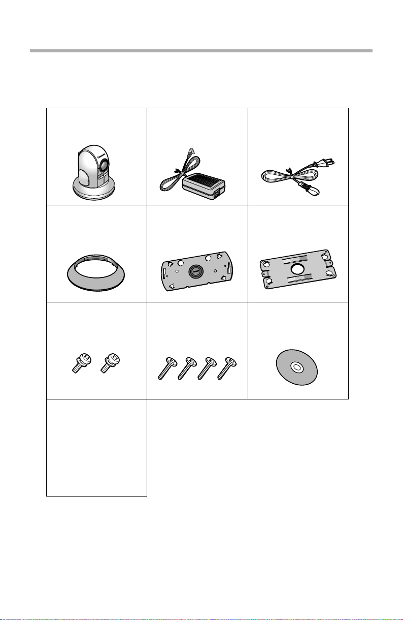
1.2 Included Items
The following items are included in the Network Camera box. Additional pieces
can be ordered by calling 1-800-332-5368.
Main Unit—1 pc. AC Adaptor—1 pc.
Order No. PSLP1242Y
Length: 3 m (10 ft.)
Ceiling Mounting
Cover—1 pc.
Order No. PSKL1023Z1
Screws A—2 pcs.
Order No. XYN3+J6FJ
Installation/
Troubleshooting
(This Manual)—1 pc.
Ceiling Plate A—1 pc.
Order No.
PSZMHCM381A
Screws B—4 pcs.
Order No.
XTB4+20AFJ
AC Cord—1 pc.
Order No. PSJA1069Z
Length: 1.8 m (6 ft.)
Ceiling Plate A—1 pc.
Ceiling Plate B—1 pc.
Order No.
Order No.
PSZMHCM280M
PSMD1045Y
Setup CD-ROM—1 pc.
Order No.
PSQX3620ZCD
[For assistance, please call: 1-800-272-7033] 9
Installation/Troubleshooting
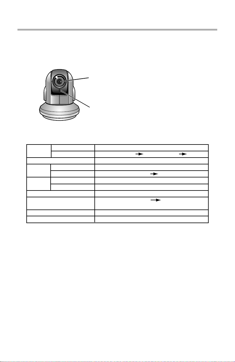
1.3 Camera Feature Locations
1.3.1 Front View
Auto Focus/Zoom Lens
Wide: 5 mm (0.2 inches)—Infinity
Tele: 1 m (39.4 inches)—Infinity
Indicator
The indicator color shows camera status.
Indicator Display
Powe r
on
Automatic
Setup
Using
DHCP
DEFAULT RESET button
Not on the LAN
On the LAN
Normal Operation*
Finished setting
Getting IP address*
Got IP address
Updating Firmware
Pressing FACTORY
TM
Failure Orange blinking (About a 2-second interval)
UPnP
Internal Failure Red blinking*
1
Setting
Orange blinking Green
2
Orange blinking
Green blinking
Green blinking
Green blinking
Orange blinking
Orange blinking Turning off
(The camera restarts after that.)
Green blinking
Green
Green
Green
3
*1 The indicator turns orange if the camera is not connected to the LAN.
*2 The indicator blinks orange if the camera is not connected to the LAN.
*3 See page 40.
10
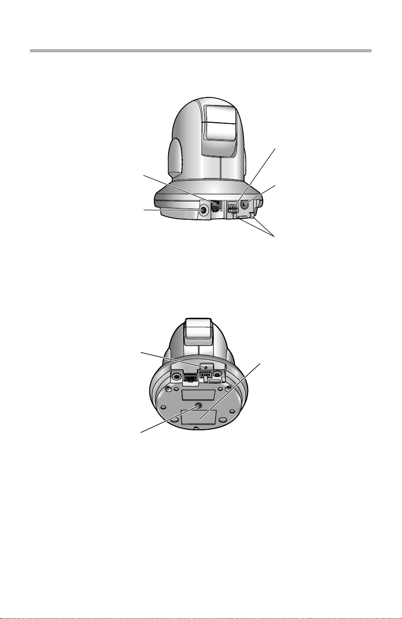
1.3.2 Rear View
Ethernet (LAN) port
(See page 12)
Analog Video Output
(See page 14)
1.3.3 Bottom View
Installation/Troubleshooting
External I/O
(See page 119 of the
Operating
Instructions on the
Setup CD-ROM)
DC IN jack
(See page 13)
Hook for AC adaptor
cord
(See page 13)
FAC TO RY DEFAULT
RESET button
(See page 121 of the
Operating Instructions on
the Setup CD-ROM)
Hole for Ceiling Plate A
(See page 35)
[For assistance, please call: 1-800-272-7033] 11
MAC Address and Serial
Number are indicated on
the label.
Installation/Troubleshooting
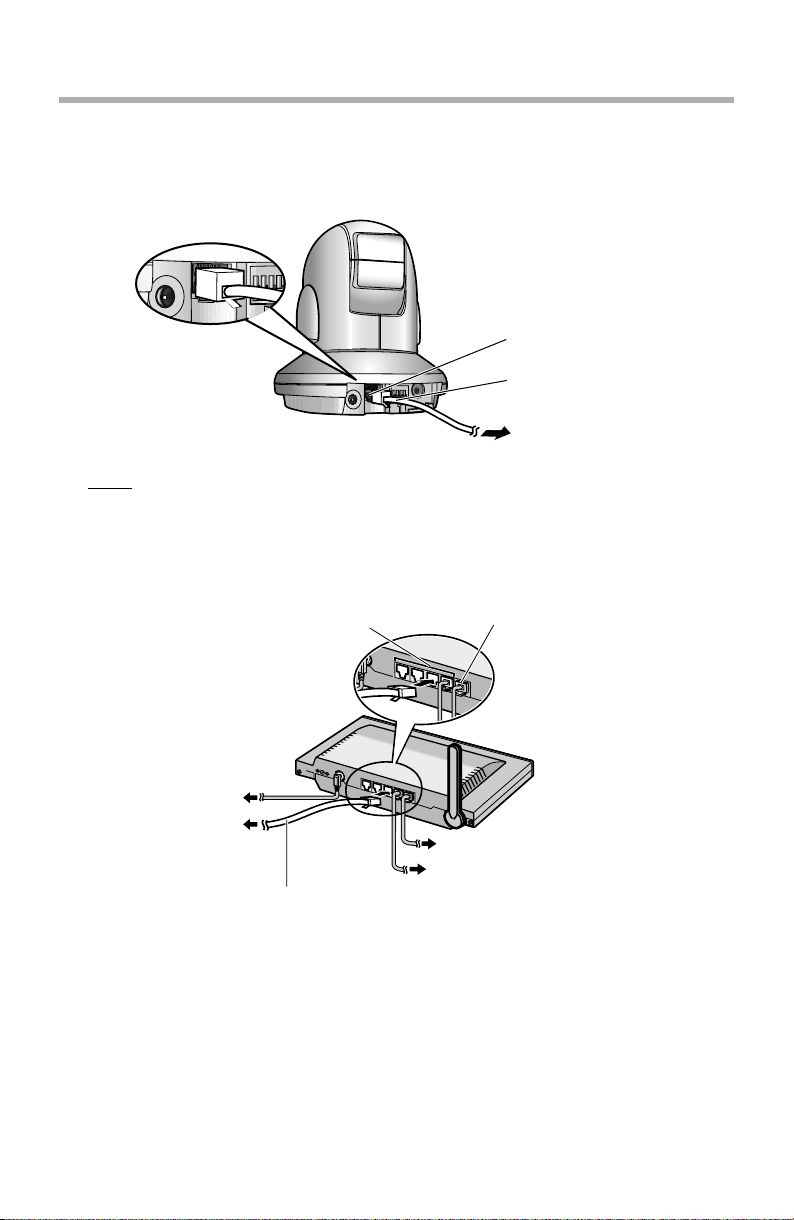
1.4 Connecting the Camera to Your Router
Connect the camera to your router with an Ethernet cable to set up the camera.
1. Connect the Ethernet cable (customer-provided) to the camera.
Ethernet port
Ethernet cable
To your router
Note
These instructions assume your PC is already connected to the Internet and
your network includes a router.
2. Connect the Ethernet cable to your router.
LAN ports WAN port
12
To the outlet
To the camera
To your modem
To your PC
Ethernet cable (Straight Cat5 cable)
(Customer-provided)
Installation/Troubleshooting
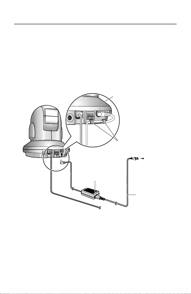
3. Connect the AC adaptor cord to the DC In jack, and plug the AC cord into the
outlet.
• The AC cord is used as the main disconnect device, ensure that the
socket-outlet is located/installed near the equipment and is easily
accessible.
• Use only specified Panasonic AC adaptor PSLP1242 (Order No.
PSLP1242Y).
• If the indicator does not light green, see page 39.
• A noise can be heard during pan/tilt operation. This is normal.
4. Hook the AC adaptor cord to the Hook for AC adaptor cord.
DC IN jack
Hook for AC adaptor cord
Power Outlet
AC adaptor
AC cord
[For assistance, please call: 1-800-272-7033] 13
Installation/Troubleshooting
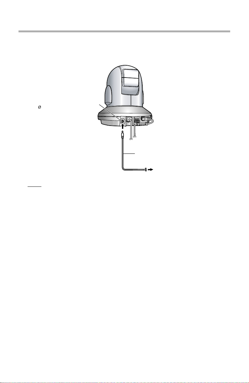
1.5 Connecting the Camera to Your TV
You can view camera images on a TV or record them using a video recording
device (VCR, DVD recorder, etc.).
Analog composite (NTSC)
video output terminal
( 3.5 mm plug 1Vp-p, 75Ω)
Video cable (not included)
To video input terminal
Note
• When the camera is in color night view mode, images may not be
displayed correctly on the TV.
14
Installation/Troubleshooting
1.6 Setting up the Camera to View on the LAN
Setup CD-ROM allows you to easily set up the camera.
Note
• To avoid any possible problems, temporarily disable any firewall or
antivirus software.
• This procedure explains installation of the camera on the same network
that your PC is part of.
• Before proceeding, close your web browser.
• See page 132 of the Operating Instructions on the Setup CD-ROM for
details.
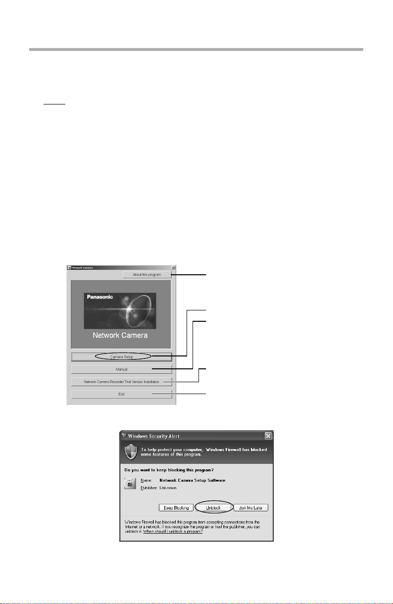
1. Insert the Setup CD-ROM into the CD-ROM drive of the PC.
• The window is automatically displayed.
(If the Network Camera Setup window is not displayed automatically,
double-click "Setup.exe" file on the Setup CD-ROM.)
2. Click [Camera Setup].
Displays version information
about this program.
Sets up the camera.
Displays the camera manuals.
If your PC does not have Adobe®
Acrobat® Reader®, install it from
the Adobe Reader website.
Installs Network Camera
Recorder trial version.
Closes the Setup Program.
• When the following dialog is displayed, click [Unblock].
[For assistance, please call: 1-800-272-7033] 15
Installation/Troubleshooting
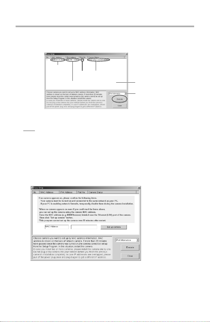
3. Select the camera to set up and click [Execute].
• This program searches for the cameras that are connected to the router
and displays the MAC Addresses, IP addresses and Port Numbers.
MAC
Address
IP
Address
• The MAC Address (see page 11) on the bottom of the camera shows
which camera you select on the Camera List window.
Note
• If more than 20 minutes have passed since the camera was turned on, the
camera cannot be set up from the Setup Program. In this situation,
disconnect the AC cord from the outlet, and reconnect it again.
• The Setup Program may not list any cameras due to your firewall or
antivirus software settings on your PC. If you cannot disable your firewall
or antivirus software, you can set up the camera entering the camera MAC
address on the following window. The camera's MAC address can be
found on the label affixed to each camera. See page 27 for details.
Por t
No.
Camera
Status
Camera
List window
Displays IPv4 or
IPv6 information.
16
Installation/Troubleshooting
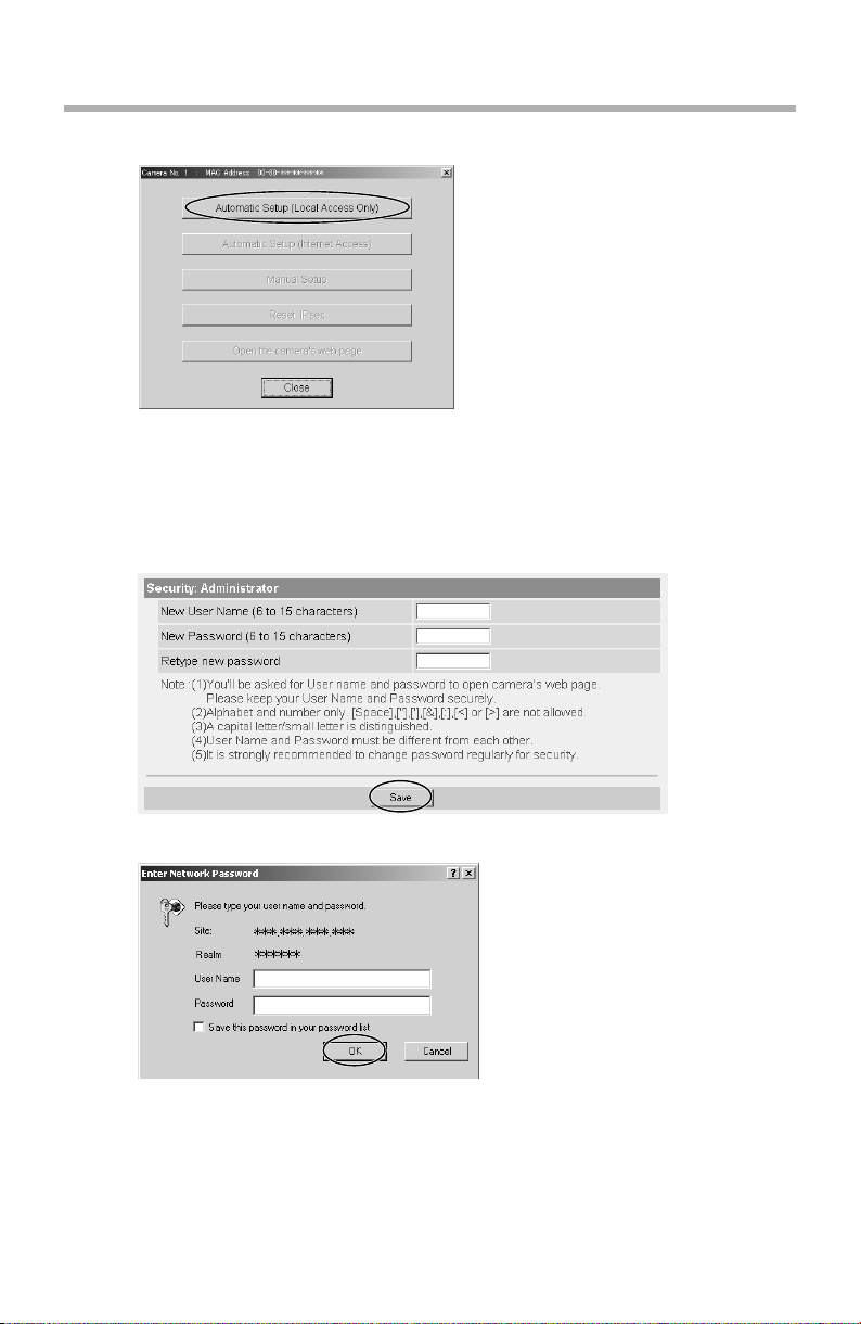
4. Click [Automatic Setup (Local Access Only)].
• For the first time installation or after pressing the FACTORY DEFAULT
RESET button, only [Automatic Setup (Local Access Only)] can be
selected. To set up the camera with Static or DHCP settings, after
performing the [Automatic Setup (Local Access Only)], run the Setup
Program again and select [Manual Setup].
5. Enter the user name and password you wish to use, and click [Save].
6. Enter the name and password that were entered above, and click [OK].
[For assistance, please call: 1-800-272-7033] 17
 Loading...