

Panasonic KX-HCM280 User Manual

Network Camera
Operating Instructions
Model No.
KX-HCM280
Please read this manual before using and save this manual for future reference.
Panasonic Network Camera Site: http://www.panasonic.com/netcam
for customers in the USA or Puerto Rico

Operating Instructions
Introduction
Thank you for purchasing a Panasonic Network Camera.
Check the following items when unpacking.
Network Camera
Operating Instructions
Getting Started
AC Adaptor
AC Cord
Ceiling Mounting Cover
Ceiling Plate A
Ceiling Plate B
Setup CD-ROM
Screws A
Screws B
For operation assistance:
• Call 1-800-272-7033
• Refer to the Panasonic Network Camera Site
http://www.panasonic.com/netcam
— 1 pc.
— 1 pc.
— 1 pc.
— 1 pc.
— 1 pc.
— 1 pc.
— 1 pc.
— 1 pc.
— 1 pc.
— 2 pcs.
— 4 pcs.
2

Operating Instructions
Trademarks
• Netscape and Netscape Navigator are either registered trademarks or
trademarks of Netscape Communications Corporation in the U.S. and other
countries.
• Adobe and Acrobat are either registered trademarks or trademarks of Adobe
Systems Incorporated in the United States and/or other countries.
• Ethernet is either a registered tra demark or a tradema rk of Xerox Corpora tion
in the United States and/or other countries.
• Microsoft, Windows, Windows NT, MS-DOS, Hotmail and ActiveX are either
registered trademarks or trademarks of Microsoft Corporation in the United
States and/or other countries.
• Pentium is a trademark or registered trademark of Intel Corporation or its
subsidiaries in the United States and other countries.
• Screen shots reprinted with permission from Microsoft Corporation.
All other trademarks identified herein are the property of their respective owners.
Network Camera Memo
Attach your purchase receipt here.
For your future reference
Date of purchase
Serial Number
(Found on the bottom side of the main unit)
Name and address of dealer
[For assistance, please call: 1-800-272-7033] 3
MAC Address

Operating Instructions
IMPORTANT SAFETY INSTRUCTIONS
When using this unit, basic safety precautions should always be followed to
reduce the risk of fire, electric shock, or personal injury.
Read and understand all instructions.
1.
Keep these instructions.
2.
Heed all warnings.
3.
Follow all instructions.
4.
After taking away the dust on the lens, wipe the lens with lens cleaning paper.
5.
Do not install near any he at sources su ch as radiato rs, heat regi sters, st oves,
6.
or other devices (including amplifiers) that produce heat.
Protect the AC adaptor cord from being walked on or pinched particularly at
7.
plugs, convenience receptacles, and the point where they exit from the unit.
Only use attachments/accessories such as cover and plates specified by the
8.
manufacturer.
Do not touch the unit or the AC adaptor during lightning storms.
9.
Unplug the unit when unused for long periods of time.
10.
Refer all servicing to qualified service personnel. Servicing is required when
11.
the unit has been damaged in any way, such as AC adaptor cord or plug is
damaged, the unit does not operate normally, or has been dropped.
SAVE THESE INSTRUCTIONS
4

Operating Instructions
Table of Contents
1 Product Introduction......................................................7
1.1 Getting to Know Network Camera.................................................... 8
1.1.1 Main Features.............................................................................................8
1.1.2 System Requirements..............................................................................10
1.1.3 Authentication—System Security Feature................................................11
1.2 Included Accessories...................................................................... 12
1.3 Camera Feature Locations.............................................................14
1.3.1 Front View.................................................................................................14
1.3.2 Rear View.................................................................................................15
1.3.3 Bottom View..............................................................................................15
2 Network Camera Setup................................................16
2.1 Installation Procedure.....................................................................17
2.2 Network Camera Configuration Type............................................. 18
2.3 How to turn on Network Camera for Installation.............................20
2.4 Network Parameters.......................................................................21
2.4.1 Preparing the Network Parameters for Network Camera.........................21
2.4.2 Setting IP Address of the PC in [Type 4] Configuration Type...................24
2.5 Proxy Server Setting....................................................................... 26
2.6 Simple Installation using the Setup CD-ROM................................. 28
2.7 Network Camera Access from the Internet..................................... 32
3 Network Camera Screen and Setup Window.............35
3.1 Network Camera Flow Chart .......................................................... 36
3.2 Top Page........................................................................................37
3.3 Single Camera Screen ................................................................... 40
3.3.1 Using Operation Bar................................................... ...... ..... ...................42
3.3.2 Using Pan/Tilt Operation................. ...... ..... ...... ..... .................................. ..43
3.3.3 Zooming in and out............................... ..... ...... ..... .................................. ..45
3.3.4 Automatic and Manual Focusing ..............................................................46
3.3.5 Setting Preset Positioning and Home Positioning....................................48
3.3.6 Viewing Buffered Image Screen...............................................................51
3.4 Multi-Camera Screen...................................................................... 53
3.5 Viewing Images from Network Camera on TV ...............................54
3.6 Setup Page....................................................................... ....... ...... . 55
[For assistance, please call: 1-800-272-7033] 5

Operating Instructions
3.6.1 Go to Top Page.........................................................................................59
3.6.2 Network.....................................................................................................60
3.6.3 Name/Time................................................................................................64
3.6.4 Security: Administrator..............................................................................66
3.6.5 Security: General User..............................................................................68
3.6.6 Top View Image........................................................................................70
3.6.7 Image Transfer..........................................................................................72
3.6.8 Camera Setup...........................................................................................84
3.6.9 Multi-Camera.............................................................................................87
3.6.10 External Output Control...........................................................................89
3.6.11 Indicator Control.......................... .................................. ...... ..... ...... .........90
3.6.12 Status......................................................................................................91
3.6.13 Restart.....................................................................................................92
3.6.14 Update Firmware.....................................................................................93
3.6.15 Reset to Factory Default..........................................................................96
4 Technical Guides......................................................... 97
4.1 Mounting.........................................................................................98
4.1.1 Mounting on the Table..............................................................................98
4.1.2 Mounting on the Ceiling.............................................................................99
4.2 Interfacing to the External I/O.......................................................103
4.3 ASCII and ISO-8859-1 Character Table.......................................105
4.4 Maintenance.................................................................................107
5 Specifications and Troubleshooting........................ 108
5.1 Network Camera Reset Procedure—Default Settings..................109
5.2 Default Settings List...................................................................... 110
5.3 Specifications ...............................................................................116
5.4 Troubleshooting............................................................................119
5.5 Confirmation of Network Camera Operation ................................127
5.6 FCC and Other Information ..........................................................129
Index................................................................................. 131
6

Section 1
Product Introduction
Operating Instructions
[For assistance, please call: 1-800-272-7033] 7

Operating Instructions
1.1 Getting to Know Network Camera
1.1.1 Main Features
Easy installation
Setup CD-ROM simp lifies the i nstall ation. Inser t the Se tup CD-ROM and autorun
program should start the application automatically. This program automatically
finds Network Camera on the network.
High-Speed Motion JPEG
Network Camera employs a 380,000 pixel CCD image sens or, and has an
integrated web server. Motion JPEG displays up to 30 frames per second, if the
network provides enoug h bandwid th. To con ser ve band width, JPEG - Regul arly
Refresh can be selected from Top Page. Image Resolution, Image Quality,
Refresh interval, Limit time of Continuous Motion JPEG and On the Air time
features can control the image field.
Remote Pan/Tilt/Zoom/Focus
The following features allow you to operate Network Camera fro m web browser on
your PC. High speed Pan/Ti lt operation ca n move the le ns horizontally from -175°
to +175° and vertically from -120° to 0° in mounting on the table and from 0° to
+90° in mounting on the ceiling. This movable lens allo ws you to view a wide range
of perspective from a distant place. Network Camera has 21x Zooming and
Automatic and Manual Focusing features to provide you with detailed and
distinct images. It also has Preset Positioning and Home Positionin g features
to register fixed po sitions. Clicki ng the preset bu ttons moves the l ens to registere d
preset positions. Single Camera screen has Click to Center feature too. The
object on Single Cam era screen can be centered by clicki ng on the imag e directly.
Multi-Camera Screen
Using Multi-Camera screen you can simultaneously view up to four Network
Cameras at various locations. Clicking on each Camera Name switches to the
Single Camera screen from the Multi-Camera screen.
8

Operating Instructions
Multi-Client Access
Network Camera allows up to 30 users to view Motion JPEG image
simultaneously. Users can access the Top View Image screen (Single Camera/
Multi-Camera screen) from their own lo ca tion s. Note that as the nu mber of users
simultaneously connected to Network Camera increases, the overall motion
performance will decrease.
Video Output
Network Camera has an analog com posite ou tput termin al. You can v iew images
from Network Camera on TV and record them on videotapes.
External I/O (Input/Output)
The external sensors/devices such as a door sensor can be connected via the
External Sensor Input. The external sensors/devices are customer provided.
The alarm/timer trigger can activate the Image Transfer feature, which can send
the images via e-mail or FTP (File Transfer Protocol).
External Device Control Output can send a signal to activate the external
devices such as a light around Network Camera.
Update Firmware
If new firmware is released, you can download the latest program from the
Network Camera Technical Support Site. Installation is easy and fast. Refer to
page 93 for details.
Authentication
Authentication window requires you to enter the administrator/general user ID
and password. Password sec uri ty c an pre ven t unre gis ter ed us ers /in trude rs fro m
accessing your image from their web browsers. Refer to Section
1.1.3 Authentication—System Security Feature for details.
Multi-Language Display
Top Page, Single Camera screen and Multi-Camera screen can be displayed in
English (US), English (UK), French, German, Italian, Spanish or Japanese. All
Setup windows are also changed when selecting English (US), English (UK) or
Japanese.
[For assistance, please call: 1-800-272-7033] 9

Operating Instructions
1.1.2 System Requirements
The PC (Personal Computer) and the network must meet the following technical
specifications for Network Camera to work properly.
Item Description
Operating
System
Microsoft
Microsoft Windows 2000, Microsoft Windows Me
Microsoft Windows NT
®
Windows® 95, Microsoft Windows 98/SE
®
4.0, Microsoft Windows XP
Network
Protocol
Interface 10/100 Mbps Ethernet
Web browser*
TCP/IP network protocol installed.
(HTTP, TCP, UDP, IP, DNS, ARP, ICMP)
®
card for your network connection
1
Internet Explorer 5.0 or later/Netscape Navigator® 4.7x.
(Not included on the Setup CD-ROM).
1
Network Camera image is not displayed correctly in the Netscape® v6.x.
*
Use Netscape Navigator v4.7x.
Refer to Panasonic Network Camera Site
http://www.panasonic.com/netcam for the latest information on the web
browser.
Note
®
Pentium
II 300 MHz or gr eater CPU is recommended to prevent p erformance
degradation.
The display color quality
To insure the images you are viewing are the best they can be, set the Display
property setting (color quality) to 24 bit or higher. Follow the next steps.
Close all applications so that you are looking at the Windows desktop.
1.
Right-click an open portion of the desktop.
2.
Select [Properties], [Setting] tab, and set [Color Quality] (Colors/Color Pallet)
3.
to the highest selection possible.
Note
Optimum video viewing will be seen when the color quality is set to 24bit or
higher. This ch ange should not cause any proble ms with ot her applica tions on
your PC.
10
Operating Instructions
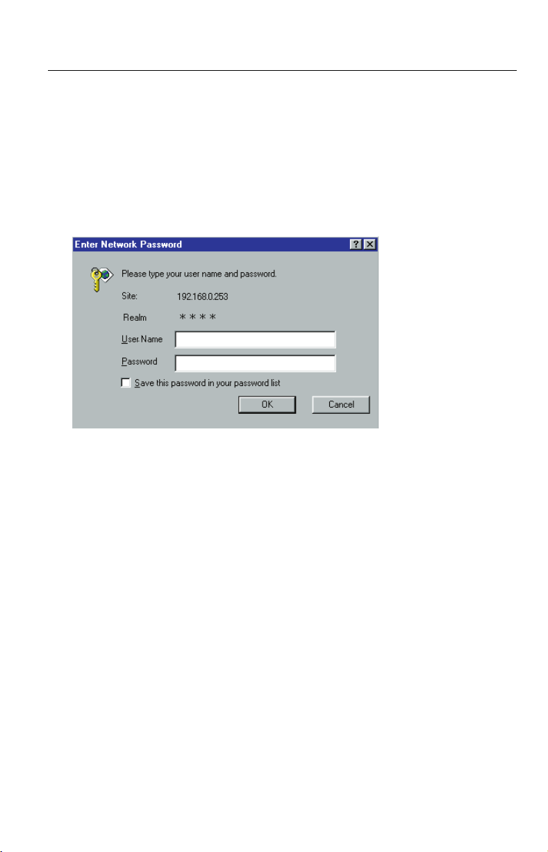
1.1.3 Authentication—System Security Feature
Authentication window requires you to enter the administrator/general user ID
and password for security. Password security can prevent unregistered users/
intruders from accessing your image from their web browsers. Authentication
windows are not displayed in the default. Refer to page 66 for setting up
Authentication window, the admi ni stra tor ID and the pass word . Refer to pag e 68
for setting up the general user ID and the password.
Authentication window
[For assistance, please call: 1-800-272-7033] 11
Operating Instructions
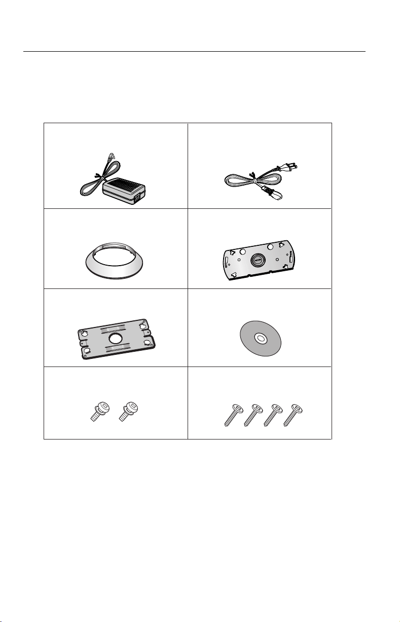
1.2 Included Accessories
The following items are p rovide d with Netw ork Came ra. Addit ional p ieces can be
ordered by calling 1-800-332-5368.
AC Adaptor—1 pc.
Order No. PSLP1242Z
Ceiling Mounting Cover—1 pc.
Order No. PSKL1023Z
Ceiling Plate B—1 pc.
Order No. PSMD1045Z
Screws A—2 pcs.
Order No. XYN3+J6FY
AC Cord—1 pc.
Order No. PSJA1069Z
Ceiling Plate A—1 pc.
Order No. PSZMHCM280M
Setup CD-ROM—1 pc.
Order No.
Screws B—4 pcs.
Order No. XTB4+20AFY
PSQX2904ZCD
12
Notes
• If any items are missing, contact the dealer immediately.
• The order numbers listed above are subject to change without notice.
• Save the original carton and packing materials for future shipping and
transportation of the unit.

Operating Instructions
Setup CD-ROM
The setup program simplifies Network Camera installation. Adobe® Acrobat®
Reader 4.05 or later enables you to see the Operating Instructions on the Setup
CD-ROM. If Adobe Acrobat Reader is not installed on the PC, double-click
"ar405eng.exe". Refer to "ReadmeEng.txt" for the directory and file structure of
the Setup CD-ROM.
Notes
• Do not scratch, smudge, write or label either surfaces of the Setup CD-
ROM. Setup CD-ROM may have a scratch on the surface.
• Do not leave the Setup CD-ROM in direct sunlight, near a heat source or
in a hot automobile as the Setup CD-ROM may become unreadable.
• Do not use chemicals or clean ser to clean the Setup CD-ROM as the Setu p
CD-ROM may become unreadable.
[For assistance, please call: 1-800-272-7033] 13

Operating Instructions
1.3 Camera Feature Locations
1.3.1 Front View
Lens (Power Focus/Zoom Lens)
Wide: 5 mm (0.2 inches)—Infinity
Tele: 1 m (40 inches)—Infinity
(Refer to page 45.)
Indicator
(Refer to page 90 for the setup.)
Indicator
Indicator can be controlled on Indicator Control window on page 90. Color
indications are shown below.
Power
on
Using
DHCP
Pushing FACTORY DEFAULT RESET button
Internal Failure of Network Camera Red blinking*
Not on the LAN
On the LAN
Normal Operation
Getting IP address
Finish getting IP address
Updating Firmware
Orange OrangeOrange blinking*
Orange Green
Green blinking
Green
Green blinking
Green
Orange blinking
Orange blinking twice
*1 Orange indicator will continue blinking in the DHCP setting.
2
Refer to page 122 for the red blinking.
*
1
2
Lens and Pan/Tilt operation
Operation bar on the Sing le Camera screen can o perate the Pan/Tilt. T he Pan/Tilt
moves the lens horizo ntal ly from -17 5 ° to +17 5° a nd verti ca lly fro m -1 20° to 0° in
mounting on the table and from 0° to +90° in mounting on the ceiling. R efer to
page 43 for the Pan/Tilt operation.
Notes
• When the power is on, do not manually revolve the Pan/Tilt. Revolving it
forcedly or moving it manually by some mistake may damage the Pan/Tilt
operation, or change the registered Pan/Tilt positions from actual ones.
Restart Network Camera when the latter case happens.
• Do not touch the lens . Touc hing it can rem ove the p rotec tive coa tin g from the
lens. Fingerprints, dust, stains, etc. on the lens can also degrade the
performance of the Automatic Focusing feature.
14
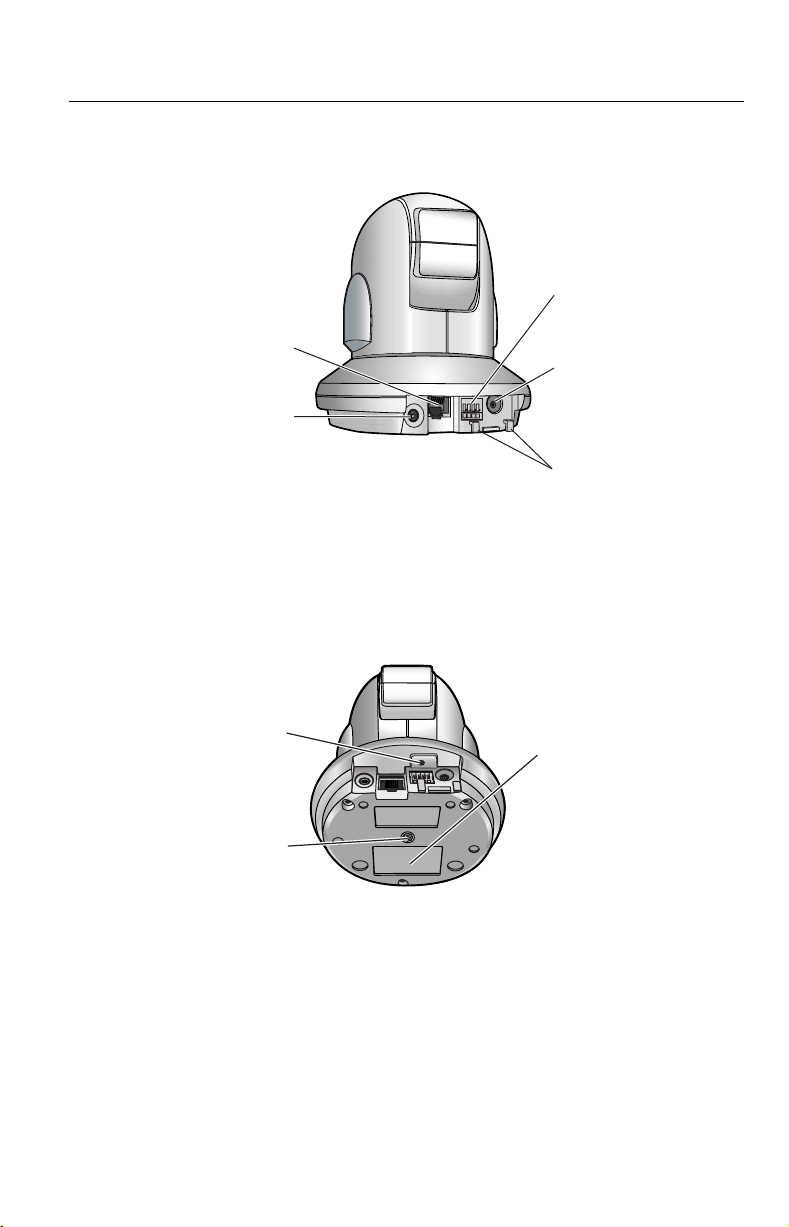
1.3.2 Rear View
Ethernet port
(10/100 Base-TX)
(Refer to page 20.)
Analog Video Output
terminal (VIDEO OUT)
(Refer to page 54.)
1.3.3 Bottom View
Operating Instructions
External I/O
(I/O)
(Refer to page 103.)
DC IN jack
(Refer to page 20.)
Hook for AC
Adaptor C o r d
(Refer to page 20.)
FACTORY DEFAULT
RESET button
(Refer to page 109.)
Hole for Ceiling Plate A
(Refer to page 100.)
[For assistance, please call: 1-800-272-7033] 15
MAC Address and Serial
Number are indicated on
the label. Record both of
them on the Network
Camera Memo on page 3.
They are indispensable
for setting network
parameters after
mounting Network
Camera and for future
customer servicing.
(Refer to page 29.)

Operating Instructions
Section 2
Network Camera Setup
16

Operating Instructions
2.1 Installation Procedure
Select the Network Camera configuration type. (Page 18—Page 19)
Connect Network Camera for installation. (Page 20)
Prepare the network parameters for Network Camera. (Page 21—Page 22)
Check the proxy server setting. (Page 26—Page 27)
Set up Network Camera with Setup CD-ROM. (Page 28—Page 31)
Confirm the Network Camera Access from the Internet. (Page 32—Page 33)
Mount Network Camera. (Page 98—P age 102 )
[For assistance, please call: 1-800-272-7033] 17
Operating Instructions
2.2 Network Camera Configuration Type
Network Camera can be connec ted over the LAN/Intrane t and the Internet. Select
from the four Network Camera configuration types. Network parameters differ
depending on the Network Camera configuration type.
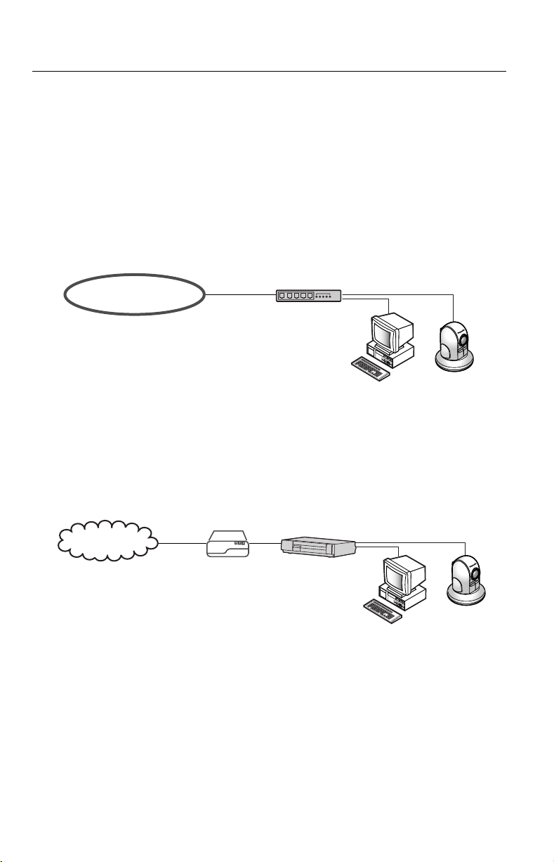
[Type 1]—LAN/Intranet Connection with an Ethernet
Switching Hub
Network Camera can be installed on the LAN/Intranet.
Ethernet switching hub*
LAN/Intranet
1
Network traffic can be improved by using the Ethernet switching hub.
*
[Type 2]—Internet Connection with a Broadband Router
Network Camera can be acces sed from the Internet. Th e broadband router n eeds
Port Forwarding (IP Masquerade) feature on page 32.
1
18
Internet
Modem
CATV
xDSL
Optical cable
Broadband
WAN LAN
Router
Operating Instructions
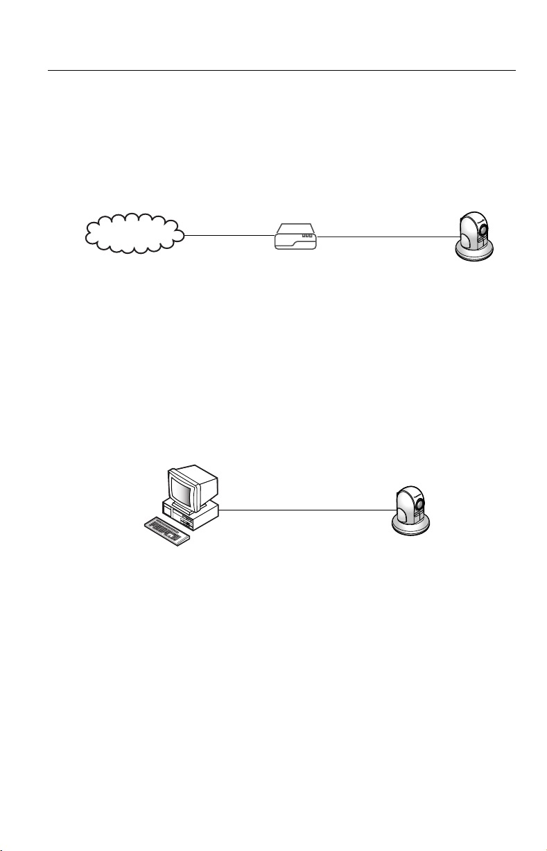
[Type 3]—Internet Direct Connection with a Modem
Network Camera can b e installed a lone without PC on the network. When you set
up Network Camera in [Type 3], connect Network Camera temporarily in [Type
1], [Type 2] or [Type 4].
Modem
Internet
Note
Some xDSL services use PPPoE. Network Camera d oes not supp ort PPPoE.
If the Internet conne ction requir es PPPoE, c onnec t with the b roadba nd rou ter
supporting PPPoE like [Type 2].
[Type 4]—Direct Connection with a PC
Network Camera can be connected to a PC directly.
Category 5 cross cable
Note
Use a category 5 cross cable when connecting directly with the cable to the
PC.
[For assistance, please call: 1-800-272-7033] 19
Operating Instructions
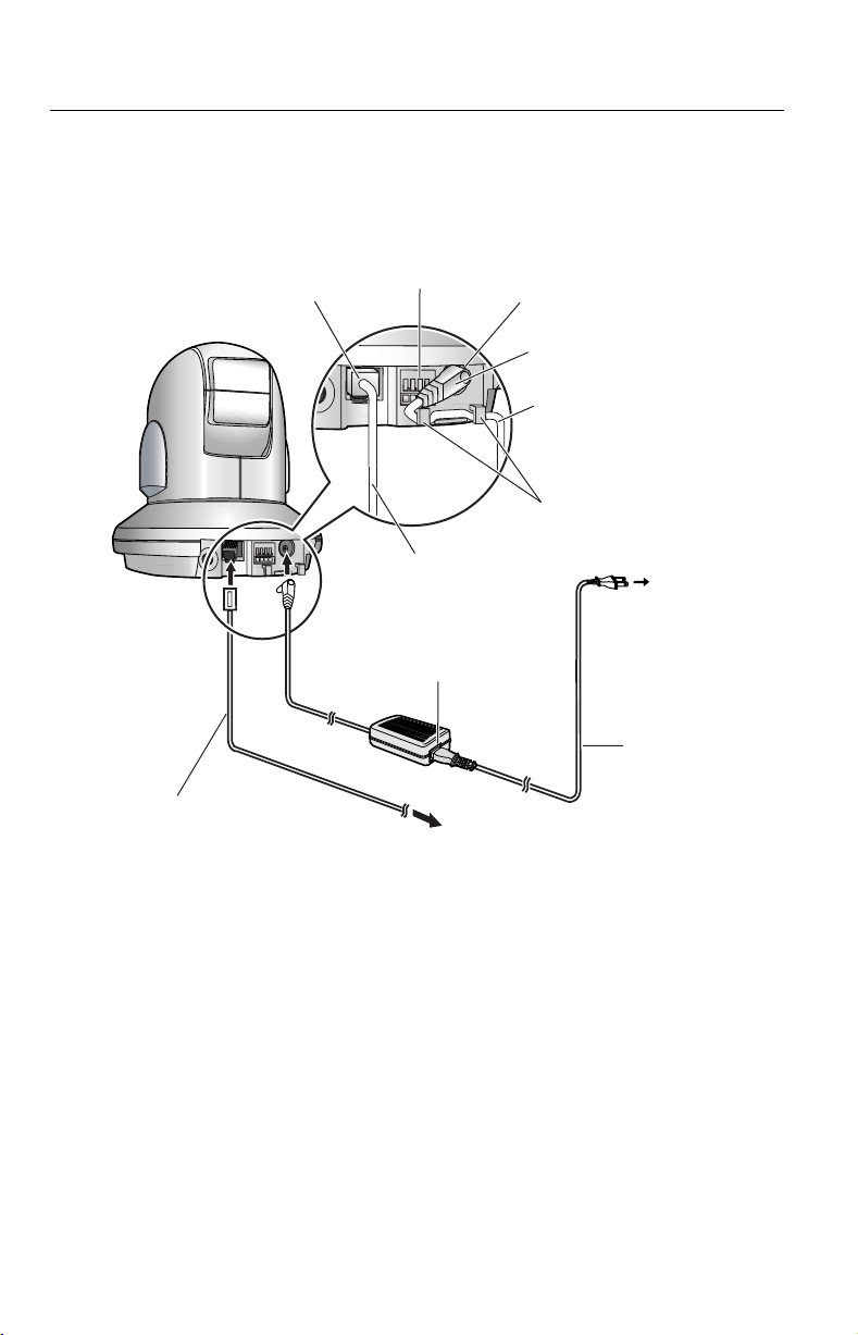
2.3 How to turn on Network Camera for Installation
Network Camera powers up when connecting AC plug to the power outlet.
Ethernet port
External I/O
3)
Connect a category 5
straight/cross cable
to the Ethernet port.
4)
Connect the AC cord
to the AC adaptor.
DC IN jack
1)
Connect the DC plug of the
AC adaptor to the DC IN jack.
2)
Hook the AC adaptor cord
to the Hook for AC Adaptor.
Hook for AC Adaptor
5)
Connect the AC plug
of the AC cord to
the power outlet.
Power Outlet
Category 5 straight/cross cable
Notes
• Do not hold or touch the Pan/Tilt as it starts moving when connecting AC
plug to the power outlet.
• AC adaptor is used as the main disconnect device, so ensure that the
power outlet is located/installed near the equipment and is easily
accessible.
• Use only specified Panasonic AC adaptor PSLP1242 (Order No.
PSLP1242Z).
• When you set up Network Camera in [Type 3], connect it temporarily in
[Type 1], [Type 2] or [Type 4].
• When Indicator is orange, confirm that the Ethernet cable is properly
connected, or PC, Ethernet hub or broadband router is properly working.
20
AC cord
To Network

Operating Instructions
2.4 Network Parameters
2.4.1 Preparing the Network Parameters for Network
Camera
Before starting to set up the network parameters of Network Camera, make note
of corresponding network parameters.
[Type 1] Ask your network administrato r for the network parameters.
[Type 2] Refer to the broadband router’s manual for the network parameters.
[Type 3] Ask your ISP (Internet Service Provider) for the ne twork paramete rs.
[Type 4] Install Network Camera in the default condition. Set the PC
"192.168.0.250" (IP address) and "255.255.255.0" (Subnet Mask).
Refer to page 24.
Refer to page 22 and page 23 for network parameters.
Network parameters memo for Network Camera
The devices on the network may not be assigned the same IP address. Each
device must have i ts own IP address. Overlap ped IP addr ess es can cause other
network devices to stop work ing and may re sult in wide spread netw ork prob lems.
IP Address . . .
Subnet Mask . . .
Default Gateway
DNS Server 2 . . .
. . .
[For assistance, please call: 1-800-272-7033] 21
DNS Server 1 . . .

Operating Instructions
Network Parameters Table
Parameters
Port No.
IP address
Subnet
Mask
Default
Gateway
[Type 1] [Type 2] [Type 3] [Type 4]
80 (default) 80 (default)
Check [Static],
and set the
static private
IP address.
Set the Subnet Mask fitted to your network.
Set Default
Gateway
address.
Network Camera Configuration Type
1
80 (default)
*
2
*
Check [Static],
and set the
static private
IP address.*
3
Set the private
IP address of the
broadband router
80 (default)*
Check [Static],
and set the
static global
IP address.*
Set Default
Gateway
address.*
1
4
4
192.168.0.253
(default)
255.255.255.0
(default)
You do not
need to set up.
(on your network),
not of the gateway
of your ISP. *
DNS
Set DNS server address.
Server 1, 2
DDNS
You do not
need to setup.
Max.
Bandwidth
Usage
1
*
Many ISP's intentionally block port number 80 to guard against network
It can restrict the transmit bandwidth.
Select from 0.1 to Unlimited Mbit/s.
3
Set DNS server
address.*
5
*
4
5
*
You do not
need to setup.
viruses. If your ISP blocks port number 80, substitute it to another unused port
number.
2
When you use more than one Network C amera with a b roadband r outer, each
*
Network Camera ne eds its ow n port numb er. The broad band router ne eds the
Port Forwarding feature. Refer to page 32.
3
Refer to the broadband router's manual for the Port Forwarding feature.
*
4
When you use Network Camera in DHCP feature, check [DHCP] and enter the
*
Host Name if your ISP requires. If y ou automatically get the address of Default
Gateway and DNS server from DHCP server, you do not need to set up.
5
Verify that your ISP supports DHCP. If your ISP supports DHCP, or if you
*
assign a domain nam e to N etwork Camera, you n eed to cont ract an d regis ter
for DDNS service. Refer to the included leaflet for DDNS service. If you set
static global IP address to Netwo rk Camera and the broadba nd router, you do
not need to register DDNS service.
22
Operating Instructions
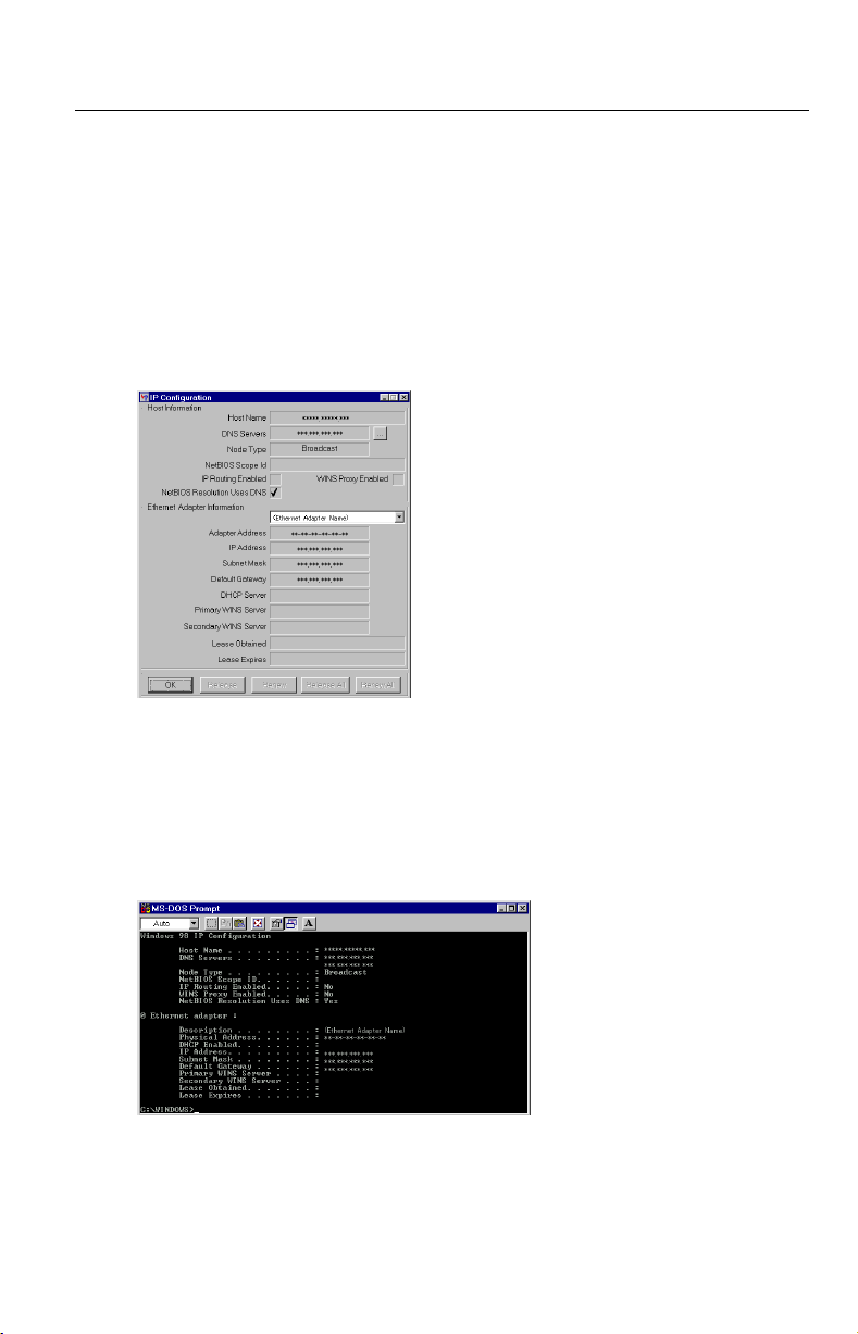
How to refer the network parameters from the PC
If you cannot get the ne twork parameters, you can refer to the netwo rk parameters
except for IP addres s from the PC on the same network in the following proc edure.
• When using Windows 95, Windows 98 or Windows Me
Click [Start] –> [Run...]. Run window appears.
1.
These steps are slightly different depending on the operating system.
Enter "winipcfg" and click [OK]. IP configuration window appears.
2.
Select the proper Ethernet adaptor and click [More Info].
3.
Click [OK] to close IP Configuration window.
4.
• When using Windows NT, Windows 2000 or Windows XP
Click [Start] –> [Program] (–> [Accessories]) –> [MS-DOS
1.
Prompt]. MS-DOS Prom pt window ope ns. These steps are sl ightly differe nt
depending on the operating system.
Enter "ipconfig /all" and press [Enter].
2.
®
(Command)
Enter "exit" and press [Enter] to close the window.
3.
[For assistance, please call: 1-800-272-7033] 23

Operating Instructions
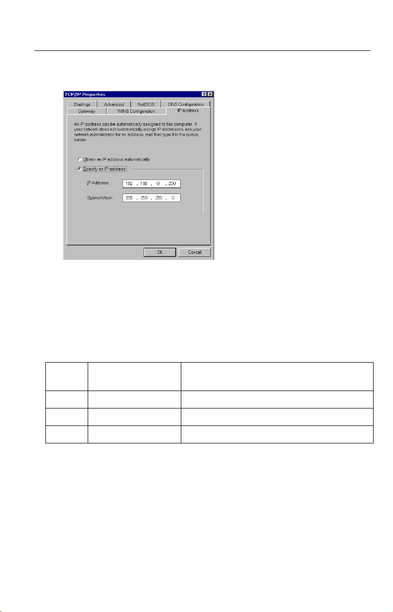
2.4.2 Setting IP Addres s of the PC in [Type 4]
Configuration Type
Your PC needs to have a static private IP address to access Network Came ra in
[Type 4] configuration.
Follow the steps be low, appropr iate for your op erating syste m to open TCP/IP
1.
Properties window on the PC.
TCP/IP Properties Table
Operating
System
Windows 95
Windows 98
Windows Me
Windows NT [Start] –> [Settings] –> [Control Panel] –> [Network] –>
Windows
2000
Windows XP [Start] (–> [Settings]) –> [Control Panel] –> [Network and
Note
When using Windows NT, Windows 2000 and Windows XP, log on as an
administrator to access TCP/IP Properties window.
[Start] –> [Settings] –> [Control Panel] –> [Network] –>
Select [TCP/IP] with adaptor in use –> [Properties] –>
[Specify an IP address]
[Protocols] tab –> [TCP/IP Protocol] –> [Properties] –>
Select [Adaptor] in use –> [Specify an IP address]
[Start] –> [Settings] –> [Control Panel] –> [Network and
Dial-up Connections] –> [Local Area Connection Icon] in
use –> [Properties] –> Select Internet Protocol [TCP/IP]
–> [Properties] –> [Use the following IP address]
Internet Connections] –> [Network Connections] –>
[Local Area Connection Icon] in use –> [Properties] –>
Select Internet Protocol [TCP/IP] –> [Properties] –> [Use
the following IP address]
Steps
24
Operating Instructions
2. TCP IP Properties window appears. Set "192.168.0.250" in the IP address
data field and "255.255.255.0" in the Subnet Mask data field.
Click [OK].
3.
Private IP address
Private IP address is the network ID that is not used on the Internet. They are
classified into Class A, Class B and Class C, as shown in the next table. Set the
IP address in the ra nge of the nu mber specifi ed in the clas s meet ing to your l ocal
network scale.
Class Subnet Mask
Class A 255. 0. 0. 0 10. 0. 0. 1 — 10. 255. 255. 254
Class B 255. 255. 0. 0 172. 16. 0. 1 — 172. 31. 255. 254
Class C 255. 255. 255. 0 192. 168. 0. 1 — 192. 168. 255. 254
[For assistance, please call: 1-800-272-7033] 25
Private IP address (I t can be set free ly within
the range in your group.)
Operating Instructions
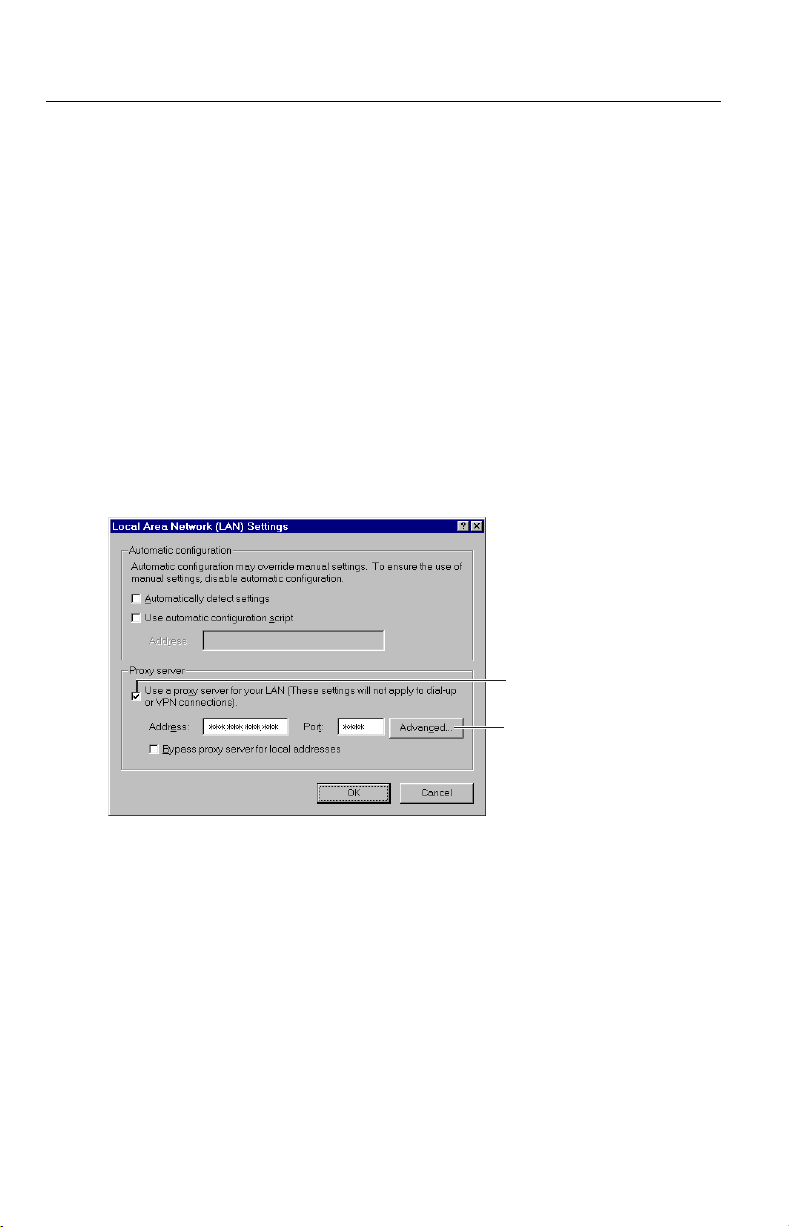
2.5 Proxy Server Setting
A proxy server may prevent you from connecting directly to Network Camera in
some corporate environments. The web browser can set up the IP address
communication without using a proxy server. Consult your ISP or network
administrator.
Note
A proxy server is generally used to main tai n securi ty on a netw ork t hat off ers
an Internet connection. Th e network of Network Camera with the pro xy server
may cause some problems to the image quality such as taking much time in
refresh interval. Consult your ISP or network administrator for details.
Start up the Internet Explorer. (The window is Internet Explorer 5.50.)
1.
Select [Tools] –> [Internet Options...] –> [Connections] tab and click [LAN
2.
Settings]. See if the Use a proxy server check box is checked or not in the
next window. When checked, click [Advanced...].
26
See if the check
box is checked or not.
When checked, click
[Advanced...].
When not checked, click [Cancel]. Your proxy settings are causin g no
problems.
Operating Instructions
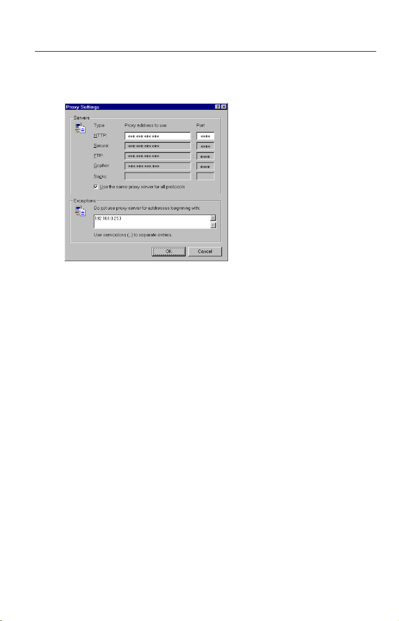
Enter the IP address of Network Camera assigned from your ISP or network
3.
administrator into the Do not use proxy server for addresses beginning
with data field.
Click [OK] on all of the opening windows.
4.
[For assistance, please call: 1-800-272-7033] 27
Operating Instructions
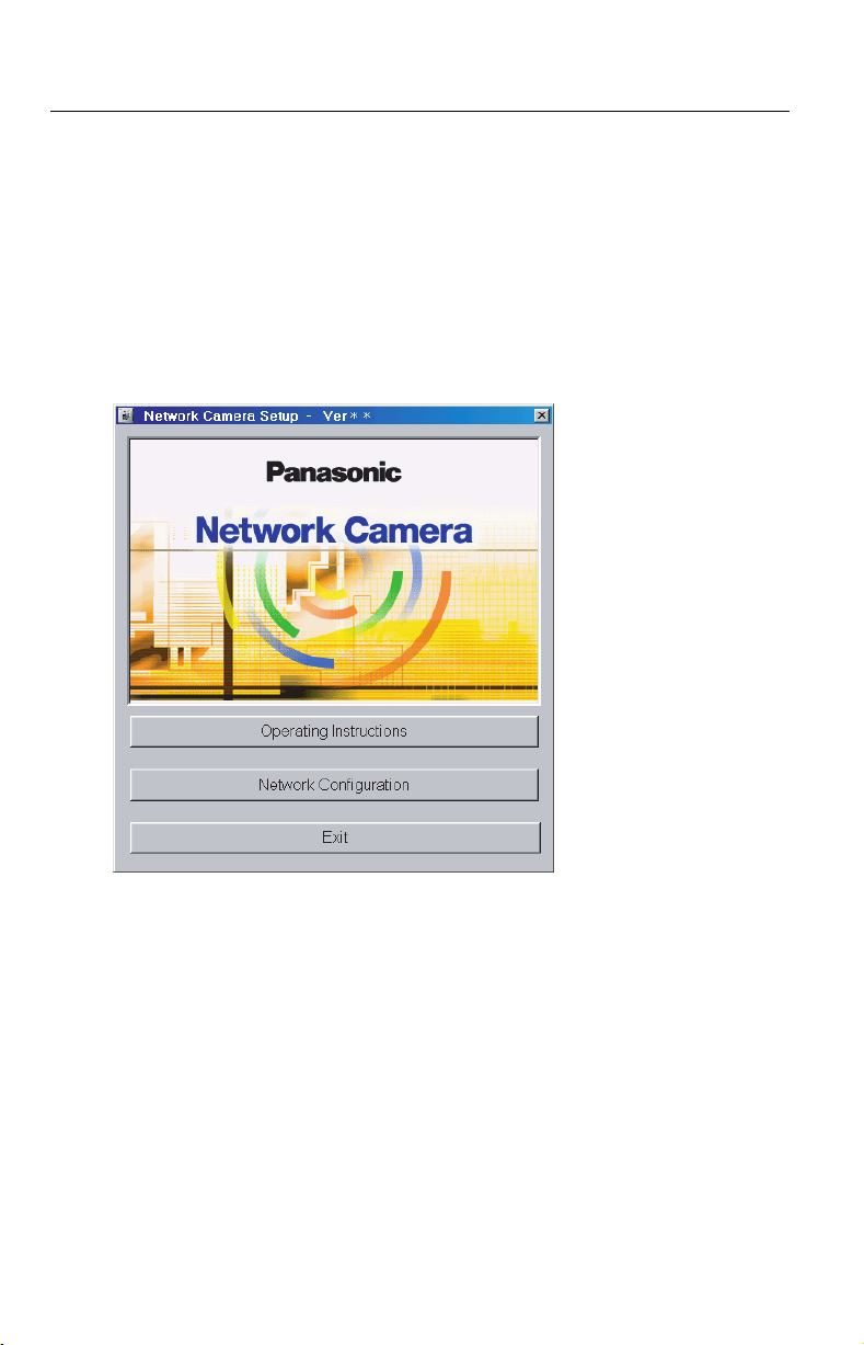
2.6 Simple Installation using the Setup CD-ROM
After finishing cabling, turn on Network Cam era and ins ert the Setu p CD-ROM in
the CD-ROM drive of the PC. Setup CD-ROM should start the application
automatically. Th is program automatic ally finds Network Cameras on the network.
Turn on Network Camera.
1.
Insert the Setup CD-ROM in the CD-ROM drive of the PC.
2.
(If Network Camera Setup window does not app ear, click "setup.exe" on the
Setup CD-ROM.)
28
Operating Instructions
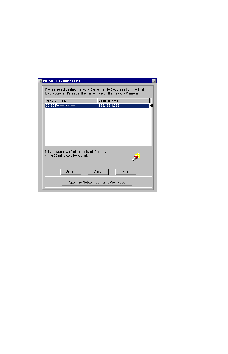
Click [Network Configuration]. Network Camera List window appears.
3.
Setup program finds a ll Network Came ras connect ed on your loc al network. It
lists all of MAC addresses and IP addresses of Network Cameras. Network
Cameras that are is olated by t he use of a home gat eway or broadb and rou ter
will not be detected . Rec ord MAC address on the Ne tw ork Cam era Me mo on
page 3. It is useful for customer servicing.
(A)
Notes
• The setup program finds and identifies Network Camera by listening for
data, which Network Camera sends out for the first 20 minutes after
powering up. If the installation is not completed within 20 minutes,
disconnect temporarily the AC adaptor to restart this operation.
• Each Network Camera has a unique MAC address labeled on the back.
Refer to page 15.
• Network Cameras that are isolated by the use of a home gateway or
broadband router will not be detected.
[For assistance, please call: 1-800-272-7033] 29
Operating Instructions
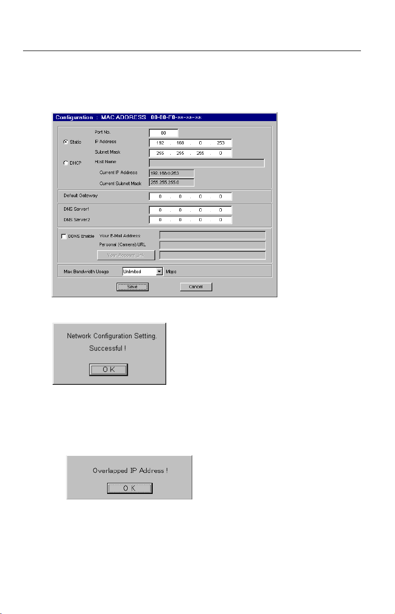
Select your target Network Camera from the list as shown in example (A) on
4.
Network Camera List window on pa ge 29 and clic k [Select]. Configuration
window appears. Refer to pag e 21 and page 22 an d enter the correct n etwork
parameters. Refer to page 61 for details of each parameter.
Click [Save] when finished. The "Successful!" message box appears.
5.
30
Notes
• Network Camera automatically restarts after saving the network
configuration.
• Overlapped IP address displays the next box. If yo u cannot set up, ask your
ISP or the administrator.
 Loading...