

Page 1

Quick Reference Guide
Digital Proprietary Telephone
Model No.
Thank you for purchasing a Digital Proprietary Telephone (DPT). Please read this
manual
carefully before using this product and save this manual for future use. For
more details, please refer to the manuals of the PBX.
Manuals and supporting information are provided on the Panasonic Web site at:
http://www.panasonic.net/pcc/support/pbx/
Note
R In this manual, the suffix of each model number is omitted unless necessary.
R The illustrations may differ from the appearance of the actual product.
KX-DT521/KX-DT543/KX-DT546
Digital DSS Console
Model No.
KX-DT590
Page 2
Important Information
Important Information
ARNING
W
Disconnect the telephone line cord from this product if this product emits smoke, an
abnormal smell, or makes unusual noise. These conditions can cause fire or
electric shock. Confirm that smoke has stopped and contact an authorized service
center.
CAUTION
To prevent damage to the telephone, be sure to unplug the extension line before
you set up or remove the KX-DT590 (Digital DSS Console).
For Users in the European Union
I
nformation for Users on Collection and Disposal of Old Equipment
and used Batteries
These symbols on the products, packaging, and/or accompanying documents
m
ean that used electrical and electronic products and batteries should not be
mixed with general household waste.
For proper treatment, recovery and recycling of old products and used
batteries, please take them to applicable collection points, in accordance with
your national legislation and the Directives 2002/96/EC and 2006/66/EC.
By disposing of these products and batteries correctly, you will help to save
valuable resources and prevent any potential negative effects on human
health and the environment which could otherwise arise from inappropriate
waste handling.
For more information about collection and recycling of old products and
batteries, please contact your local municipality, your waste disposal service
or the point of sale where you purchased the items.
Penalties may be applicable for incorrect disposal of this waste, in
accordance with national legislation.
For business users in the European Union
If you wish to discard electrical and electronic equipment, please
contact your dealer or supplier for further information.
Information on disposal in other countries outside the
uropean Union
E
These symbols are only valid in the European Union. If you wish to
discard these items, please contact your local authorities or dealer
and ask for the correct method of disposal.
2
Page 3
Important Information
Note for the battery symbol (bottom two symbol
e
xamples):
This symbol might be used in combination with a chemical symbol.
In this case it complies with the requirement set by the Directive for
the chemical involved.
For information of Compliance with EU relevant Regulatory
D
irectives, Contact to Authorized Representative:
Panasonic Testing Center
Panasonic Marketing Europe GmbH
Winsbergring 15, 22525 Hamburg, Germany
For Users in Australia and the United Kingdom
R T
his unit is capable of being used in conjunction with hearing
aids fitted with inductive coil pick-ups. The handset should be
held as for normal conversation. For operation, the hearing aid
should be set to its "T" position or as directed in the operating
instructions for the hearing aid.
R This unit is designed to aid the visually handicapped to locate dial keys and
buttons.
For Users in the United Kingdom
R T
his unit is designed to be installed under controlled conditions of ambient
temperature and a relative humidity.
R Avoid installing the unit in damp or humid environments, such as bathrooms or
swimming pools.
R 999 and 112 can be dialed on the product after accessing the outside line for the
purpose of making outgoing calls to the BT emergency (999) and (112) services.
For users in New Zealand
his equipment shall not be set to make automatic calls to the Telecom ‘111’
R T
Emergency Service.
3
Page 4

Important Information
R T
his device is equipped with pulse dialing while the telecom standard is DTMF
tone dialing. There is no guarantee that the Telecom Lines will always continue
to support pulse dialing.
PTC General Warning
R The grant of a Telepermit for any item of terminal equipment indicates only that
Telecom has accepted that the item complies with minimum conditions for
connection to its network. It indicates no endorsement of the product by
Telecom, nor does it provide any sort of warranty. Above all, it provides no
assurance that any item will work correctly in all respects with another item of
Telepermitted equipment of a different make or model, nor does it imply that any
product is compatible with all of Telecom’s network services.
4
Page 5
Accessory Information
Accessory Information
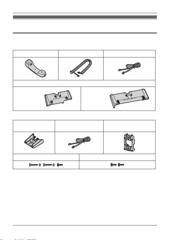
Included Accessories
K
X-DT521/KX-DT543/KX-DT546
*
Handset (1) Handset Cord (1)
Stand (1)
KX-DT521 KX-DT543
K
X-DT546
Telephone Line Cord
KX-DT590
Stand (1) Telephone Line Cord
Screws for wall mounting (3)
*1 Two cords for the KX-DT521NE/KX-DT543NE/KX-DT546NE. Consult your
ealer regarding which telephone line cord to use.
d
No cords for the KX-DT521NZ/KX-DT543NZ/KX-DT546NZ. Consult your
dealer regarding which telephone line cord to use.
One cord for models other than the above.
*2 For users in New Zealand, consult your dealer regarding which telephone line
cord to use.
*3 Two screws for attaching the KX-DT590 to a wall.
One screw for attaching the wall mounting adaptor to the unit.
*2
(
1)
*
3
Screws for attaching to the unit (2)
Wall mounting adaptor (1)
1
5
Page 6

Accessory Information
Optional Accessories
KX-DT521 KX-DT543 KX-DT546
Wall mount kit KX-A432X KX-A433X
Digital DSS Console KX-DT590
6
Page 7
KX-DT521AL/KX-DT521NZ/KX-DT521SX/KX-DT521UK/KX-DT521X
KX-DT521NE
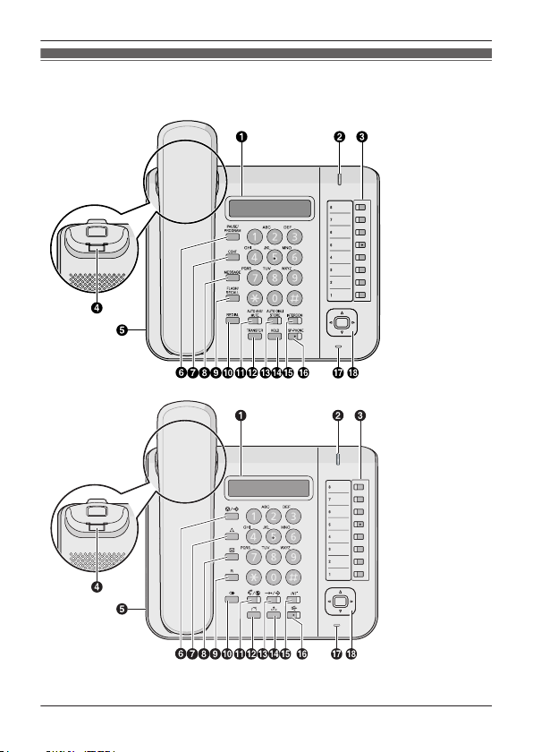
Location of Controls
Location of Controls
7
Page 8
KX-DT543AL/KX-DT543NZ/KX-DT543SX/KX-DT543UK/KX-DT543
X
KX-DT546AL/KX-DT546NZ/KX-DT546SX/KX-DT546UK/KX-DT546
X
KX-DT543NE/KX-DT546NE
Location of Controls
8
Page 9

KX-DT590AL
KX-DT590SX
KX-DT590UK
KX-DT590X
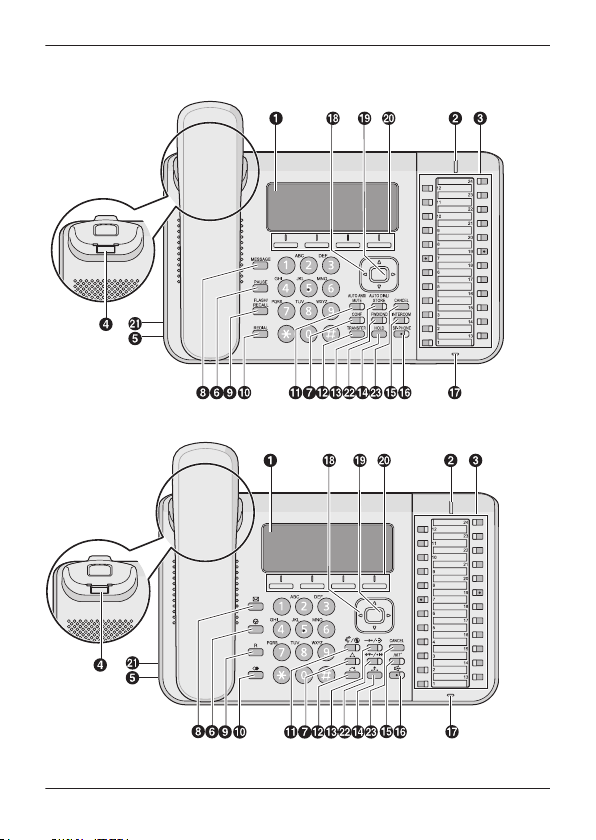
A LCD (Liquid Crystal Display):
K
X-DT521: 1 line, KX-DT543: 3 lines, KX-DT546: 6 lines
B Message/Ringer Lamp:
hen you receive an intercom call, the lamp flashes green,
W
and on an outside call, the lamp flashes red. When someone
has left you a message, the lamp stays on red.
C Flexible CO Buttons:
a feature that has been assigned to the key.
D Handset Hook:
mounted on a wall.
E Headset Jack
F V/S(
G
H
I
J
PAUSE/PROGRAM) (KX-DT521 only): Used to insert a
pause when storing a telephone number. This button is also
used for programming this unit.
V(PAUSE) (KX-DT543/KX-DT546 only): Used to insert a
pause when storing a telephone number.
(CONF):
or call back the party who left the message waiting indication.
FLASH/RECALL): Used to disconnect the current call and
(
make another call without hanging up.
(REDIAL):
Used to establish a multiple party conversation.
(MESSAGE):
Used to redial the last dialed number.
Location of Controls
Used to seize an outside line or perform
Keeps the handset stable when the unit is
Used to leave a message waiting indication
9
Page 10

Location of Controls
K
(AUTO ANS/MUTE): U
sed to receive an incoming call in
hands-free mode or mute the microphone/handset during a
conversation.
L
M
(TRANSFER):
(AUTO DIAL/STORE):
Used to transfer a call to another party.
Used for System/Personal
Speed Dialing or storing programme changes.
N
(HOLD):
O
P
(SP-PHONE [Speakerphone]):
Used to place a call on hold.
(INTERCOM): U
sed to make or receive intercom calls.
Used for performing
hands-free operations.
Q Microphone:
R Navigator Key:
Used for hands free conversations.
Used to adjust the volume and the display
contrast or select desired items.
1
S
T
*
ENTER
: Used to assign the selected item.
Soft Buttons (S1-S4)*1: S1-S4 (located from left to right) are
used to select the item displayed on the bottom line of the
display.
1
U
EHS (Electronics Hook Switch) Jack
V
FWD/DND*1: Used to switch Call Forwarding or Do Not Disturb
*
on your extension.
1
W
CANCEL
*1 KX-DT543/KX-DT546 only
*
: Used to cancel the selected item.
10
Page 11

PROG
PROG
Before Operating the Telephone
Before Operating the Telephone
Speaker volume
While in a hands-free conversation
ress [
P
Handset/Headset volume
While using the handset or headset
P
Ringer volume
While on-hook or receiving a call
P
LCD Contrast
While on-hook
1. Press the
2. Enter
3
4. Press [
5. Press [ENTER].
6. Press [CANCEL].
Ring Tone
1. Press the
2. Press a flexible CO button or
3
4. Press [ENTER].
5. Press [CANCEL].
*1 If you hear your own voice through the handset or headset, decrease the
*2 For KX-DT521, press V/S[PAUSE/PROGRAM].
*3
] or [ ] to adjust the volume.
1
*
ress [
] or [ ] to adjust the volume.
] or [ ] to adjust the volume.
ress [
*
soft button (S1).
2
.
. Press [ENTER].
*3
] or [ ] to adjust the LCD contrast.
*3
*2
2
soft button (S1).
*
[INTERCOM] 2 times.
. Enter 2 digits (01-30) using the dial keys (0-9), or press [
elect the ring tone.
s
olume.
v
For KX-DT521, press
*3
*2
[AUTO DIAL/STORE].
] or [ ] to
11
Page 12

PROG
Before Operating the Telephone
LCD Backlight
While on-hook
. Press the
1
2. Enter
3. Press [ENTER].
soft button (S1).
.
*2
4. Press a dial key to select the LCD backlight mode.
: Automatic
: Always ON
: Always OFF
5
. Press [ENTER].
6. Press [CANCEL].
*1 For KX-DT521, press V/S[
*2
For KX-DT521, press
*2
*1
*
1
PAUSE/PROGRAM].
[AUTO DIAL/STORE].
12
Page 13

Feature Operations
Making Calls
Calling
MT
o an extensionN
1. Go off-hook.
2. Dial an extension number.
MTo an outside partyN
1. Go off-hook.
2. Press a flexible CO button.
3. Dial the outside party’s phone number.
Redial
1. Go off-hook.
. Press
2
Quick Dialing
1. Go off-hook.
. Dial a quick dialing number.
2
Doorphone Call
1. Go off-hook.
2
. Enter
. Enter a doorphone number (2 digits).
3
4. After the confirmation tone, talk.
System Speed Dialing
1. Go off-hook.
2. Press [AUTO DIAL/STORE].
3. Enter a system speed dialing number (3 digits).
[REDIAL].
.
Feature Operations
13
Page 14

PROG
Feature Operations
Personal Speed Dialing
o storeN
MT
1. Go off-hook.
2. Enter
3
. Enter a personal speed dialing number (2 digits).
4. Enter the phone number to store (max. 32 digits).
5. Press
. After the confirmation tone, go on-hook.
6
MTo dialN
1. Go off-hook.
2. Press
3
. Enter
. Enter a personal speed dialing number (2 digits).
4
One-touch Dialing
o storeN
MT
1. Press the
2. Press a flexible CO button.
3. Enter
4
. Enter the number to store (max. 32 digits).
5. Press [ENTER].
6. Press [CANCEL].
MTo dialN
1. Go off-hook.
2. Press the flexible CO button assigned as a One-touch Dialing
button.
*1 Enter the outside line access number before an outside phone number.
2 For KX-DT521, press V/S[PAUSE/PROGRAM].
*
*3
For KX-DT521, press
.
.
[AUTO DIAL/STORE].
.
soft button (S1).
.
*3
*2
*
2
*1
[AUTO DIAL/STORE].
*1
14
Page 15

Feature Operations
During a Conversation
Call Hold
o holdN
MT
1. Press
2. After the confirmation tone, go on-hook.
MTo retrieve a call at the holding extensionN
1. Go off-hook.
2. Press a flexible CO button or [INTERCOM].
MT
o retrieve an outside call from another extensionN
1. Go off-hook.
2. Press a flexible CO button.
Call Transfer
o an extensionN
MT
1. Press
. After the confirmation tone, dial an extension number.
2
3. Talk.
4. Go on-hook.
MTo an outside partyN
1. Press
. After the confirmation tone, press a flexible CO button.
2
3. Dial an outside phone number.
4. Talk.
5. Go on-hook.
[HOLD].
[TRANSFER].
[TRANSFER].
15
Page 16

Feature Operations
Setting the Telephone According to Your Needs
Do Not Disturb
1. Go off-hook.
. Enter
2
3
. Press a dial key to select the setting.
: Both outside and intercom calls
: Outside calls only
: Intercom calls only
4
. To enable Do Not Disturb, enter
T
o cancel Do Not Disturb, enter
5
. After the confirmation tone, go on-hook.
Timed Reminder
o setN
MT
1. Go off-hook.
2. Enter
3. Enter the hour and minute (4 digits).
4. If 12-hour-time display is set, enter
5. Enter (1 time) or (daily).
6. After the confirmation tone, go on-hook.
MTo cancelN
1. Go off-hook.
2. Enter
3. After the confirmation tone, go on-hook.
MTo stop or answer the ring backN
1. Press
.
.
.
.
(AM) or (PM).
.
[INTERCOM], or go off-hook.
16
Page 17

Feature Operations
Useful Features
Multiple Party Conversation
o add other parties during a conversationN
MT
1. Press
2
. After the confirmation tone, dial the phone number of the party to
[CONF].
add.
3. Talk to the new party.
4. Press
. After the confirmation tone, talk with multiple parties.
5
[CONF].
MTo leave a conferenceN
1. Press
. After the confirmation tone, go on-hook.
2
[CONF].
Before Leaving Your Desk
Call Forwarding
1. Go off-hook.
. Enter
2
3. Press a dial key to select the types of calls to apply this feature to.
: Both outside and intercom calls
: Outside calls only
: Intercom calls only
4
. Press a dial key to select the status.
: All calls
: Busy
: No answer
: Busy/No answer
: Cancel
5. Enter an extension number, and then enter
ccess number, an outside phone number, and then enter
a
. After the confirmation tone, go on-hook.
6
*1
f you enter
I
.
1
*
in Step 4, you can skip Step 5.
, or enter a CO line
.
17
Page 18

Installation and Setup
Installation and Setup
ote
N
R Panasonic assumes no responsibility for injuries or property damage resulting
from failures arising out of improper installation or operation inconsistent with this
documentation.
Attaching a KX-DT590 to the KX-DT543/KX-DT546
The KX-DT590 allows 48 additional Flexible CO
b
uttons to be added to this unit. These buttons are
used to seize an outside line, make a call using
One-touch Dialing, or perform a feature that has been
assigned to the key.
ttach the KX-DT590 to
1 A
your unit with the 2
*1
screws.
*1 Included with the KX-DT590.
Attaching the Stand
X-DT521
K
1 Insert the catches of the stand into the hooks located in the unit.
2 Gently push the stand in the direction indicated until it locks into
place.The stand will be mounted.
18
Page 19

1
A
Installation and Setup
KX-DT543/KX-DT546/KX-DT590
1 Insert the catches (
2 G
ently push the stand in the direction indicated until it locks into
place. The stand will be mounted in the high position.
Example: KX-DT546
) of the stand into hooks located in the unit.
Removing the Stand
X-DT521
K
1 R
emove the stand in the
direction indicated while
pushing the catches of the
stand with both hands as
shown.
KX-DT543/KX-DT546/KX-DT590
1 H
old the stand with both
hands.
2 Gently rotate the stand in
the direction indicated
until it is released.
Example: KX-DT546
19
Page 20

To a handset jac
k
(handset)
Connect to:
a digital proprietary telephone
— Digital XDP connection
Connect to a PBX.
The telephone line cord
Clamp
Headset jack
KX-DT521
Clamp
KX-DT543/KX-DT546
Headset
EHS jack Headset jack
Connect to:
a digital proprietary telephone
— Digital XDP connection
a single line telephone
— XDP or parallel connection
Connect to a PBX.
The telephone line cord
To a handset jack
(handset)
Installation and Setup
Connections
20
Page 21

Connect to a PBX.
The telephone line cord
Clamp
KX-DT590
Installation and Setup
Note
R W
hen connecting a headset
The following headsets can be used with this unit. (Not all operations with the
headsets can be guaranteed.)
– Wired headsets
Panasonic RP-TCA400, RP-TCA430, KX-TCA400 or KX-TCA430
– EHS headsets (KX-DT543/KX-DT546 only)
For up-to-date information about headsets that have been tested with this unit,
please contact your dealer.
http://www.panasonic.net/pcc/support/pbx/
R When connecting cords
Ensure the cords are inserted in the grooves, and are clamped to prevent
damage to the connectors.
21
Page 22

Wall Mounting
Wall Mounting
ote
N
R When mounting the KX-DT543/KX-DT546 with a KX-DT590 on the wall, attach
the KX-DT590 to the KX-DT543/KX-DT546 first, and then mount them on the
wall. For detail about the attaching, see “Attaching a KX-DT590 to the
KX-DT543/KX-DT546”, Page 18.
R When mounting the KX-DT543/KX-DT546 with a KX-DT590 on a wall, only ONE
KX-DT590 can be attached.
1 Insert the tabs of the wall mounting adaptor into the designated
openings in the base, and then slide the wall mounting adaptor in
the direction of the arrow until it clicks.
KX-DT521
KX-DT543/KX-DT546 with KX-DT590
22
Page 23

83 mm
100
mm
4
Washer
Drive the screw
to this point.
222 mm
2
3
40 mm or less
The telephone line cord
Wall Mounting
2 F
asten the wall mounting adaptor(s) to the base with the screw(s).
(Recommended torque: 0.4 N·m [4.08 kgf·cm] to 0.6 N·m
[6.12 kgf·cm])
3 Connect the cables to the unit, and run the cables through the wall
mounting adaptor, as shown in the illustration below.
4 Drive the screws into the wall either 83 mm or 100 mm apart, and
mount the unit on the wall.
Example: KX-DT543/KX-DT546 with KX-DT590
23
Page 24

83 mm
100 mm
100 mm
83 mm
for KX-DT521/KX-DT543/KX-DT546
for KX-DT590
222 mm
One screw here
One screw at either point
One screw at either point
One screw here
WALL MOUNTING TEMPLATE
1. Drive the screws into the wall as indicated.
Note:
• If the KX-DT590 is mounted beside a
KX-DT543/KX-DT546, leave 222 mm
of space between the 2 screws
for the DPT and the 2 screws for the
KX-DT590, as indicated above.
This space is abbreviated in this template
and must be measured.
2. Hook the unit onto the screw heads.
© Panasonic System Networks Co., Ltd. 2014
PNQX6339YA PP0114MK2036
 Loading...