

Panasonic HQ-2101SH, HQ-2121SH User Manual
ROOM AIR CONDITIONER
OPERATING INSTRUCTIONS
MODEL: HQ-2101SH
HQ-2121SH
ENGLISH
Please read these operating instructions thoroughly before using
your air conditioner and keep them for future reference.
For assistance, please call: 1-800-211-PANA (7262) or send e-mail to
consumerproducts@panasonic.com
or refer to
www.panasonic.com
F563445
1
Please observe these following safety precautions when using
your air conditioner.
• Failure or negligence in observing these safety precautions
could cause fire, electrical shock or personal injury.
This symbol (with a white background) denotes
an action that is PROHIBITED.
These symbols (with a blue background) denote
actions that are COMPULSORY.
INSTALLATION PRECAUTIONS
• Due to the weight of this product, we recommend that
you have a helper to assist in the installation. To avoid
injury, use the proper method of lifting. Avoid any sharp
SAFETY PRECAUTIONS
edges.
• Make sure the window frame to be used can properly
support this product.
• This product must be installed in accordance with all local
codes and ordinances.
• Do not install the unit in places where inflammable gas,
fumes or soot may be generated.
OPERATION PRECAUTIONS
• Operate your air conditioner from a stable 115 volt AC
supply.
• Plug into a separate 15 amp grounded outlet only.
• Use of extension cords
Avoid using extension cords. If there are no alternatives,
ensure that the cord is a UL listed 3-wire grounding type,
rated 125 volts with a minimum current-carrying rating of
15 amps, number 14 or heavier wire.
• Use a 15 amp time delay fuse or a circuit breaker.
• Do not switch off by unplugging the power plug while it is
operating. Press the OFF/ON pad to “OFF” before
unplugging.
POWER SUPPLY
OPERATION PRECAUTIONS
WARNING
• Do not modify the length of the power cord or use an
extension cord.
• Do not touch or operate with wet hands. Do not modify
or damage the cord.
• Do not turn on the unit by inserting the power plug. Do
not switch off the unit by pulling out the power plug.
• Avoid an extended period of direct airflow.
• Do not insert sticks, fingers or other objects into the unit.
• Do not try to repair the unit yourself.
• Plug in properly before operating and use a specified
power cord.
• If abnormal conditions (burnt smell, etc) occur, switch off
and remove the power plug.
CAUTION
• Do not use the unit for other purposes, than its intended
use.
• Do not remove the power plug by pulling the cord.
• Do not block the air intake and outlet vanes.
• Do not splash or direct water at the unit.
• Do not expose the unit to direct sunlight during operation.
• Do not operate the unit without the air filter installed or
when the front intake grille has been removed.
• Do not place any objects on the unit.
• Do not operate any combustion equipment near the unit’s
airflow area.
• Switch off the breaker and remove the power plug from
the socket if the unit will not be operated for a long period.
• Pay attention to any damages on the unit caused by
extensive usage.
• Ventilate the room occasionally where the unit is installed.
• Remove the power plug when cleaning the unit.
This sign warns of risk of death or serious injury.
This sign warns of injury or damage to property.
2
Time Delay Fuse : 15 Amps
Rated Voltage : 115V
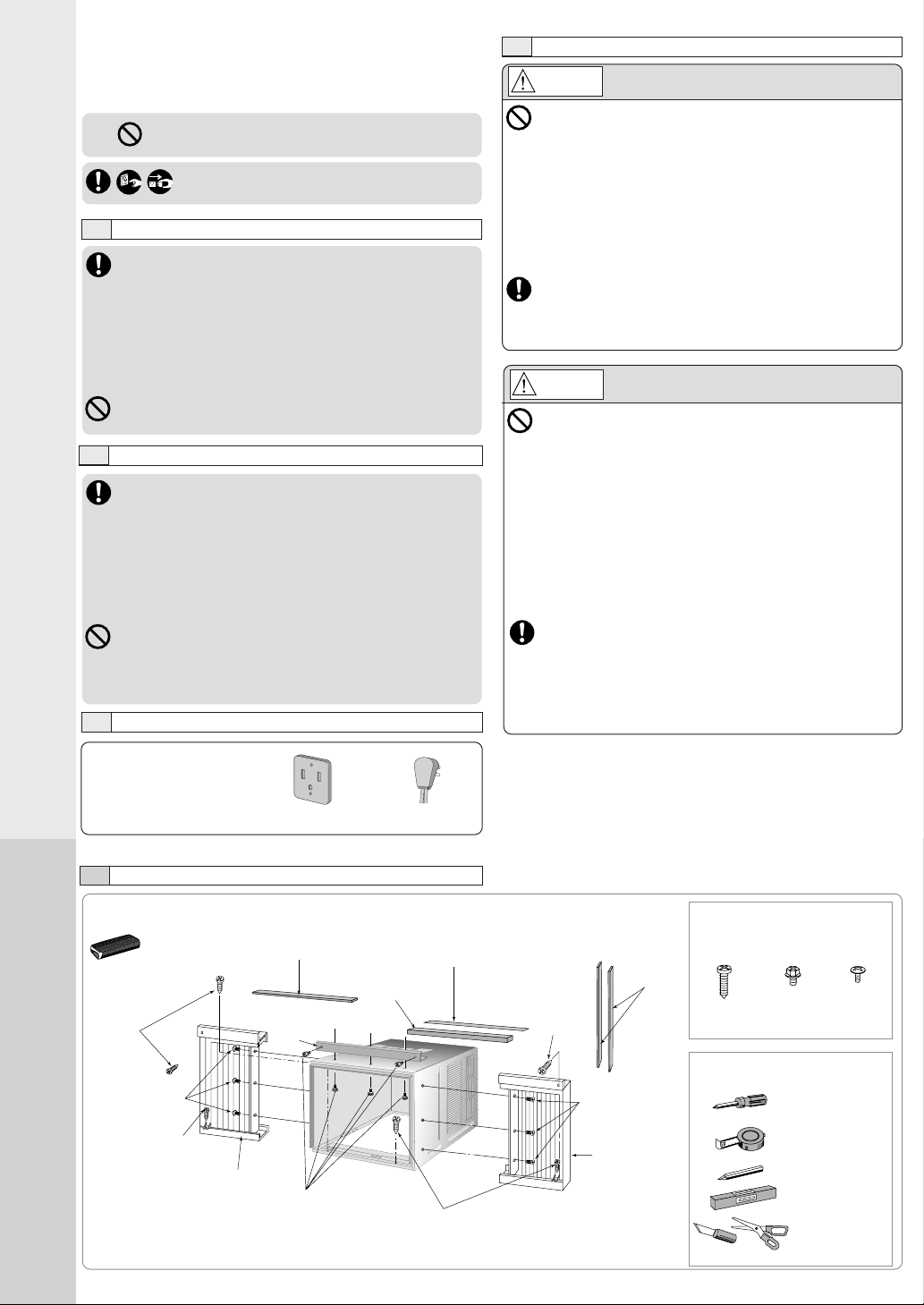
INSTALLATION BOX CONTENTS
Sealer 50 g
(1.8 oz) (Putty)
Type A
screws
Type A screw
Left side expandable panel
AIR CONDITIONER INSTALLATION
• Socket Type
Top sealing
ribbon
Top
angle
Type B
screws
• Line Cord Plug
Window sash
foam seal
Window sash
sealing ribbon
Type A
screws
Type A
screw
Type C
screws
Right side
expandable
panel
Side
sealing
ribbon
SCREW FURNISHED
Type A Type B Type C
(Qty 6) (Qty 5) (Qty 6)
Wood Machine Tapping
Screw Screw Screw
SUGGESTED TOOL LIST
Medium sized
screwdriver (#2
Phillips)
Tape Measure
Pencil
Level
Knife or
Scissor
2
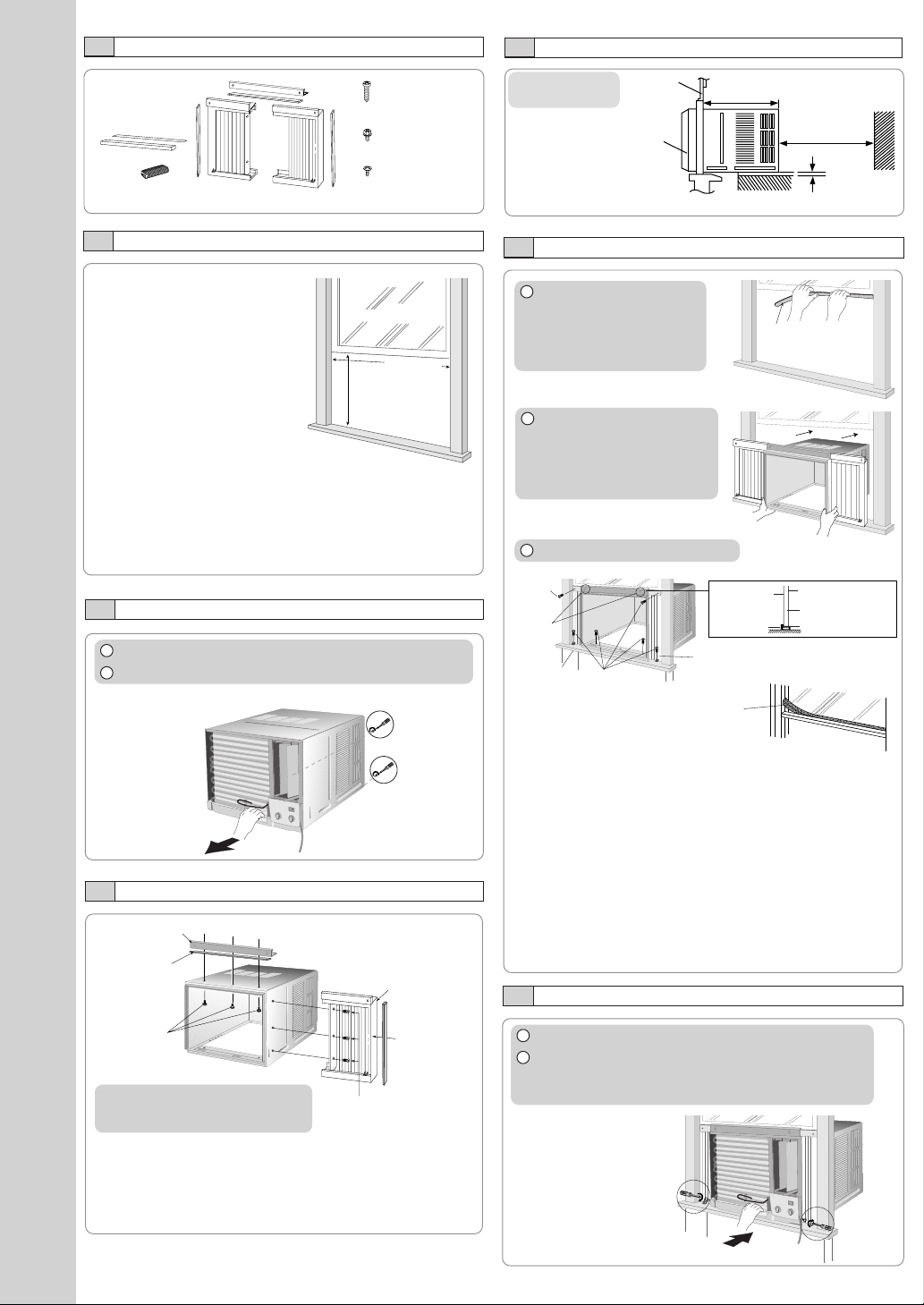
ACCESSORIES
NOTE
Check that none of the accessories are missing.
(6 pcs)
XTN5D25A
(5 pcs)
CWH4580211
(6 pcs)
XTT4D10C
SELECT THE BEST LOCATION
(Single or Double
Window
hung window)
Front grille
19–3/
inches
16
SIDE VIEW
12 inches
More than
4 inches
AIR CONDITIONER INSTALLATION
WINDOW REQUIREMENTS
• Hot sun rays hitting the outside
surface of the cabinet will
create considerable heat load.
If the outside of the cabinet is
exposed to direct sunlight,
1
(min)
/16”
15
15-
22
to 42-
/
8
”
consider building an awning to
shade the cabinet while
providing ample area for the
heated air to be exhausted
from the condenser (both
sides) and the top.
This unit is designed for
installation in standard double hung windows.
NOTE
The unit may also be installed “through the wall”. Y ou should,
however, observe standard carpentry practices and frame
the opening without violating local ordinances.
INSTALLATION PROCEDURES
1 Remove the rear cabinet screws and save for later use.
2 Slide the chassis out from the cabinet.
CABINET INSTALLATION
1 Cut the “Sealing Ribbon”
to the proper length, and
attach it along the bottom
edge of the bottom
window sash.
2 To prevent condensation
water from dripping inside,
the cabinet should be
installed level or very
slightly tilted to the outside.
3 Secure the cabinet using screws.
Type A
screw
Type B
screws
Window sill
Type A
screws
Window sash foam seal
Window sash
sealing ribbon
Inside of
sash
Top angle
Expandable panel
Outside of sash
Window sash
Sealing ribbon
HOW TO ASSEMBLE THE EXPANDABLE PANELS
Top angle
Top sealing
ribbon (To be
attached to
the top angle)
Type B
screws
NOTE
This procedure applies to left and right
of assembling expandable panel.
Expandable panel
Side sealing
ribbon (To be
attached to the
expandable
panel)
Type C screws
• Attach the top angle to the cabinet using screw type B (3
pcs).
• Insert expandable panels to cabinet sides as shown.
• Secure the first fold of expansion panel to cabinet using screw
type C (3 each).
• Expand the expandable panel fully into the grooves of the
window frame, secure the expandable panel, left, right and
top mounting frames to the bottom of the window sash
using 4 screws type A and 2 screws type B.
• Secure the cabinet using wood screws type A.
• Cut the window sash foam seal to the proper size and
seal the opening between the top of the inside window
sash and the outside window sash.
NOTE
If a gap exists between the unit and window sash, you may
use “Sealer” supplied with the installation kit for a better
seal.
CHASSIS INSTALLATION INTO THE CABINET
1 Slide the chassis into the cabinet.
2 Reinstall the cabinet screws.
Secure the cabinet to chassis by using screws (from
rear cabinet).
INSTALLATION OF THE FRONT GRILLE
OFF/ON
OPERATION
T
E
M
P
/T
IM
E
R
COOL
FAN
HIGH
MED
LOW
MODE
FAN SPEED
S
E
T
T
I
M
E
R
S
ET/
C
A
N
C
EL
AIR SWING
E
C
O
N
O
M
Y
h
r
°F
W
ireless
Rem
ote C
ontrol
REMOVAL OF FRONT GRILLE
Depending upon the location
of the AC outlet, route the AC
cord to either the left or right
side while installing the front
grille.
This figure shows the AC cord
routed to the left side.
1 Place the front grille on
the cabinet first.
2 Secure the front grille to
the main chassis using
screw provided.
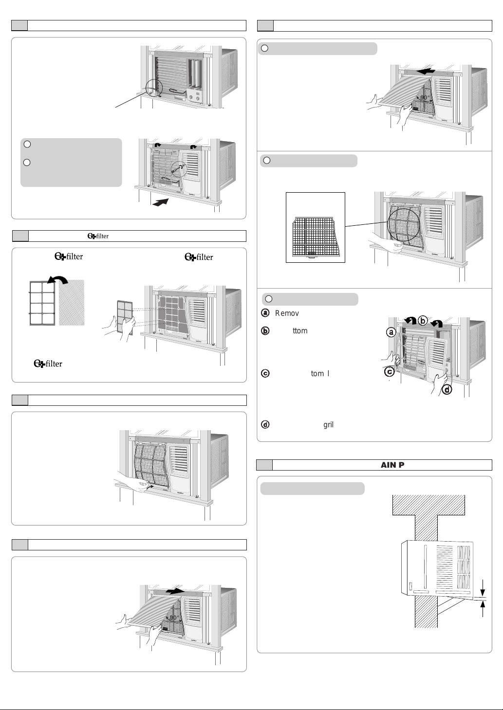
INSERT THE (OPTIONAL)
Attach the (part no.
CZ-SF6P) to the frame.
Slot in the and the
frame (part no. CZ-SFW6P) to
the front grille.
The and the frame can be obtained separately
from your nearest servicenter.
INSERT THE AIR FILTER
Attach the air filter to the intake grille.
1 Remove the front intake grille.
Pull up the front intake
grille about 90° and slide
it slightly to the left to
unhook the tabs.
2 Remove the air filter.
Tilt up and pull out the air filter
by the holder.
Air filter
3 Remove the front grille.
aa
a
Remove the adhesive tape from
aa
all sides of the front grille.
bb
b
At bottom right side of the front
bb
grille, press inward on cabinet
aa
a
aa
bb
b
bb
near the power cord, and pull
the grille outward to the right
until right tab releases.
cc
c
cc
c
At the bottom left side, push
cc
cc
inward on cabinet and pull the
grille outward to the left to
dd
d
dd
release the left tab. Do not pull
the bottom edge toward you more than 3 inches to prevent the two
top tabs from damage.
dd
d
Slide the front grille upwards to free the two top tabs from slots
dd
at the top of the cabinet.
°F
TIMER
OPERATION
TEMP/TIMER
h
r
SET
OFF/ON
SET/
CANCEL
C
O
O
L
F
A
M
N
O
D
E
A
IR
S
W
IN
G
E
C
H
O
IG
N
H
O
M
Y
M
E
D
F
A
N
S
P
E
E
D
L
O
W
W
ireless
R
e
m
o
te
C
o
n
tr
o
l
PLACE FRONT INTAKE GRILLE OVER THE FRONT GRILLE
Slide the front intake grille slightly to the right to reattach the
tabs and then push it down to close tight.
°
F
T
I
M
E
OPERATION
R
T
E
M
P
/T
IM
E
R
h
r
S
E
T
O
SET/
FF/O
N
C
A
N
C
EL
COOL
FAN
MODE
AIR SWING
E
C
HIGH
O
N
O
M
Y
MED
FAN SPEED
LOW
W
ireless
R
em
ote C
ontrol
Lift up about 90°.
HOW TO ATTACH THE DRAIN PAN (OPTIONAL)
Condensed water drainage
This air conditioner employs a
“Slinger-Up System” which is
designed to splash the condensed
water on the condenser coil for
maximum cooling efficiency, thus
producing a splashing sound.
If the splashing sound annoys you,
you can provide an outside drainage
by using the following procedure
which may, however , cause a small
loss of performance.
NOTE
The cabinet should be installed tilted
slightly lower to the rear for
necessary condensate drainage.
(Max. 13/32”)
Condensed water
Maximum
13/32”
2
HOW TO ATTACH THE DRAIN PAN (OPTIONAL)
AIR CONDITIONER INSTALLATION
3
1 Remove the rubber plug and
slide the chassis out from the
cabinet.
Remove the
rubber plug
2 Install the optional drain pan (part no. CWH40175).
Install the drain pan at the
right corner of the cabinet
using 2 screws (part no.
INTERNAL VIEW
CWG86C733).
NOTE
The drain pan (part no.
CWH40175) can be
Screws
Drain pan (optional)
obtained from nearest
servicenter.
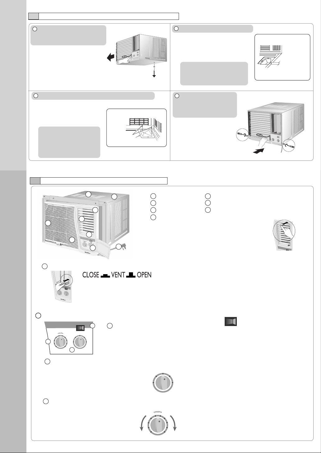
MAIN UNIT
1
2
6
4
7
8
5
9
3
3 Connect a drain hose (optional).
Fit the drain hose to the drain pan.
NOTE
Drain hose or tubing can be
purchased locally to satisfy
your particular needs.
4 Slide the chassis back
into the cabinet.
Reinstall the cabinet to
chassis by using screws.
1 Air inlet louver 4 Air filter
2 Cabinet 5 Front intake grille
3 Power cord 6 Front grille
7 Vertical airflow direction vane
(Airflow direction adjustment up-down).
The vertical airflow direction vane is controlled by
rotating the horizontal vane forward or backward.
EXTERNAL VIEW
Drain hose
(not included)
Under-side view with drain
pan and hose in place.
A
IR
S
W
IN
G
O
F
F
PART IDENTIFICATION
8 Ventilation lever
8
O
F
F
2
9
1
10
conditions. When fresh air is necessary in the room, set the ventilation lever to the OPEN
HIG
H
CO
O
L
position. The damper is opened and room air is drawn out.
The ventilation lever must be in the CLOSE position in order to maintain the best cooling
AIR SWING
OFF
ON
TH
ER
M
O
STAT
65
4
H
IG
H
FAN
LO
W
7
FAN
3
LOW
CO
O
L
9 Main control panel
AIR SWING
OFF
THERMOSTAT
65
7
4
3
c
2
10
1
ON
HIGH
FAN
LOW
LOW
COOL
FAN
8
OFF
9
b
b Main Control Knob
Low fan speed operation (without cooling)
c Thermostat Control Knob
a
a Air Swing Switch
OFF Stops the operation of Air Swing.
HIGH
COOL
ON Air Swing is in operation.
Stops all operation
For decreased cooling
AIR SWING
ON
OFF
(Only for LOW COOL, MED COOL, HIGH COOL and ECONOMY
operation.)
High fan speed operation (without cooling)
LOW
FAN
OFF
THERMOSTAT
4
3
2
1
HIGH
FAN
Low fan speed with cooling operation
LOW
COOL
HIGH
High fan speed with cooling operation
COOL
65
7
For increased cooling
8
9
10
 Loading...