

Panasonic GXL-N12FB Installation Manual
INSTRUCTION MANUAL
Inductive Proximity Sensor
GXL-N12Fغ
I/O CIRCUIT DIAGRAMS
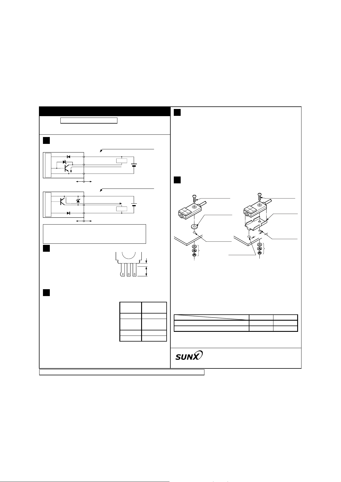
1
٨ NPN output type
1
D
Z
D1
r1
T
Sensor circuit
Internal circuit Users' circuit
٨ PNP output type
r2
T
2
D
Sensor circuit
Internal circuit Users' circuit
Symbols...D1, D2:
2
ZD1, ZD2: Surge absorption zener diode
r1: NPN output transistor
T
r2: PNP output transistor
T
SOLDERING
٨ To solder the terminals of the
sensor observe the following
conditions. Soldering temperature: 260 or less Soldering
time: 5 sec. or less Soldering position: 1.5mm, or more, away
from the sensor body.
SENSING RANGE
3
٨
Please use it by 2mm or less. However, this value is a value over a
standard detection object (iron 20
20t1mm). With a non-ferrous metal, the sensing range is obtained by
multiplying with the correction coefficient specified on the right.
٨
Keep in mind that detection distance becomes short when a detection object is small.
Further, the sensing range also changes if the sensing object
٨
(Brown / +V) +V
(Black / OUT) Output
100mA max.
(Blue / 0V) 0V
(Brown / +V) +V
Z
D2
Reverse supply polarity protection diode
100mA max.
(Black / OUT) Output
(Blue / 0V) 0V
Front sensing
Color code / Terminal symbol
Load
+
12 to 24V DC
r10%
-
Color code / Terminal symbol
+
12 to 24V DC
r10%
-
Load
1.5mm
Correction coefficient
Sensing
object
Stainless steel
(SUS304)
Brass
Aluminum
Correction
coefficient
Iron
0.70 approx.
0.40 approx.
0.35 approx.
Soldering
position
1
CAUTIONS
4
٨
If power is supplied from a commercial switching regulator,
ensure that the frame ground (F.G.) terminal of the power
supply is connected to an actual ground.
٨
The output does not incorporate a short-circuit protection circuit.
Do not connect it directly to a power supply or a capacitive load.
٨
Do not run the wires together with high-voltage lines or power
lines or put them in the same raceway. This can cause malfunction due to induction.
Do not use during the initial transient time (10ms) after the
٨
power supply is switched on.
٨
Extension up to total 100m is possible with a 0.3mm2, or more, cable.
However, in order to reduce noise, make the wiring as short as possible.
MOUNTING
5
<One point fixing>
٨
Do not use a washer between the sensor and the mounting screw.
The tightening torque be 0.49N㨯m or less.
٨
Influence of surrounding metal
٨
When there is a metal near the sensor, keep the minimum
separation distance specified in the figures shown on the reverse side.
Mutual interference prevention
٨
When two or more sensors are installed in parallel or face to
face, keep the minimum separation distance specified below
to avoid mutual interference.
Refer to the figures shown on the reverse side.
Between 'I' type and non 'I' type
Between two 'I' types or two non 'I' types
Note: Close mounting is possible for up to two sensors. When mount-
ing three sensors or more, at an equal spacing, in a row, the
minimum value of dimension 'A' should be 4mm.
is plated.
SUNX Limited
This bag is a product made from polyethylene. Even if it burns, harmful gas is not generated.
M3 (length 12mm)
truss head screw
(Accessory)
Rubber washer
(Accessory)
M3 0.5mm
tapped hole
(Depth: 10mm
or more) or Ǿ
3.4mm thru-hole
If mounting using
nut and washers
(Accessories)
Head office: 2431-1 Ushiyam-cho, Kasugai-shi,
Overseas Sales Dept.: Phone: +81-(0)568-33-7861
<Two point fixing>
Ǿ2.5mm hole
(Depth: 3mm or more)
Aichi, 486-0901,Japan
Phone: +81-(0)568-33-7211
M3 (length 12mm)
truss head screw
16mm
If mounting using
nut and washers
(Accessories)
A
0mm (Note)
20mm
PRINTED IN JAPAN
M3 0.5mm
tapped hole
(Depth: 10mm
or more) or Ǿ
3.4mm thru-hole
(Accessory)
MS-GXL12-1
(Accessory)
15mm
40mm
B
 Loading...