

Panasonic FX-100-Z, MEUEN-FX100Z Instruction Manual
1
InstructIon Manual
Digital Fiber Sensor
FX-100-Z Series
MEUEN-FX100Z V1.0
Thank you for purchasing products from Panasonic Electric Works SUNX
Co., Ltd. Please read this Instruction Manual carefully and thoroughly for
the correct and optimum use of this product. Kindly keep this manual in a
convenient place for quick reference.
WARNING
● Never use this product as a sensing device for personnel protection.
● In case of using sensing devices for personnel protection, use prod-
ucts which meet laws and standards, such as OSHA, ANSI or IEC
etc., for personnel protection applicable in each region or country.
1
cautIons
● This product has been developed / produced for industrial use only.
● Make sure that the power supply is off while wiring.
● If a voltage exceeding the rated range is applied, or if an AC power
supply is directly connected, the product may get burnt or damaged.
● Short-circuiting the load or incorrect wiring may burn or damage the
product.
● Do not run the wires together with high-voltage lines or power lines
or put them in the same raceway. This can cause malfunction due to
induction.
● Verify that the supply voltage variation is within the rating.
● If power is supplied from a commercial switching regulator, ensure that
the frame ground (F.G.) terminal of the power supply is connected to
an actual ground.
● If noise generating equipment (switching regulator, inverter motor, etc.)
is used in the vicinity of this product, connect the frame ground (F.G.)
terminal of the equipment to an actual ground.
● Do not use during the initial transient time (0.5s) after the power sup-
ply is switched on.
● You can extend the cable up to 100m max. with 0.3mm
2
or more
cable. However, in order to reduce noise, make the wiring as short as
possible.
● Make sure that stress is not applied to the sensor cable joint, e.g. by
forcible bending or pulling.
● Take care that the product is not directly exposed to uorescent lamp
from a rapid-starter lamp, a high frequency lighting device or sunlight,
etc. as it may affect the sensing performance.
● This product is suitable for indoor use only.
● Avoid dust, dirt, and steam.
● Take care that the product does not come in contact with oil, grease,
organic solvents, such as thinner, etc., strong acid or alkalines.
● This product cannot be used in an environment containing inam-
mable or explosive gases.
● Never disassemble or modify the product.
● EEPROM is adopted to this product. Teaching is limited to 100,000
times because of the EEPROM's lifetime.
2
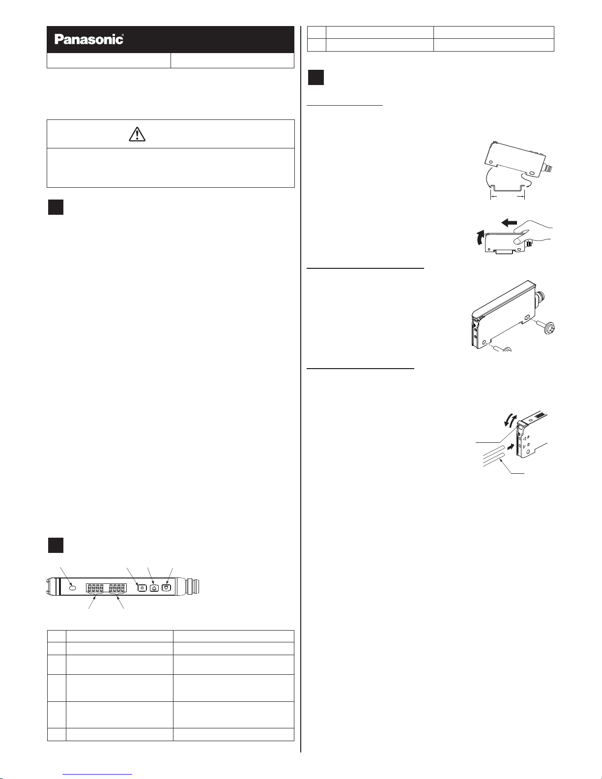
Part DEscrIPtIon
1
65
432
no. Part Description
1
Output indicator (orange) Lit when output is active.
2
Mode key ● Select mode
● Conrm settings
3
ON key / Set value UP key ● Select settings in teaching mode
● Increase set value
● Select various other settings
4
OFF key / Set value DOWN key ● Select settings in teaching mode
● Decrease set value
● Select various other settings
5
Green digital display Threshold value
no. Part Description
6
Red digital display Incident light intensity
3
MountInG
When using a DIn rail
* You may break the spring hook if you do not follow the mounting
instructions carefully.
How to mount the amplier
1. Fit the spring hook on a 35mm DIN rail and
push forward.
2. Slip the front part of the mounting section
over the DIN rail and release.
1
2
35mm
How to remove the amplier
1. Push the amplier forward.
2. Lift up the front part of the amplier.
1
2
When using screws with washers
Use M3 screws with washers to mount the
amplier.
Do not use a tightening torque of more than 0.5
N•m or you may break the housing.
M3 screw
with washers
How to connect the ber cable
Be sure to t the attachment to the bers rst before inserting the bers into
the amplier. For details, refer to the Instruction Manual enclosed with the
bers.
1. Snap the ber lock lever down until it
stops completely.
2. Slowly insert the ber cables into the
inlets until they stop (see note).
If the ber cables are not inserted until
they stop, the sensing range reduces.
Since a exible ber is easily bent, be
careful when inserting it.
3. Return the ber lock lever to the original
position.
1
3
2
Fiber lock
lever
Fiber
* If the cable is a coaxial reective type ber, e.g. FD-G4 or FD-
FM2, insert the single-core ber cable into the beam-emitting
inlet “P” and the multi-core ber cable into the beam-receiving
inlet “D.” If they are inserted in reverse, the sensing perfor-
mance will deteriorate.
2
4
WIrInG
● Use the cable with the connector CN-24A-Cq(optional)when con-
necting this product.
● Tighten the xing ring of the cable with connector completely by hand
when mounting. The tightening torque: 0.3 to 0.4N•m.
● Make sure to hold the side surface of this product when tightening or
loosening the xing ring of the cable with connector.
● If the xing ring is tightened by a tool such as pliers, the connector
may be damaged.
● If the tightening torque is not enough, the xing ring may loosen due to
vibration, etc.
Attaching the connector cable
connection method
Insert the cable with connector CN-24A-Cqas
shown. Tighten the xing ring.
Fixing ring
Cable with
connector
CN-24A-C□
Disconnection method
Loosen the xing ring, and, holding the xing
ring, pull to separate the connector.
Fixing ring
* Before disconnecting the cable, loosen the xing ring com-
pletely. If the cable is pulled by excessive force (15N or more)
when the xing ring is tightened, the cable may break.
connector pin arrangement
1
2
4
3
connector pin no. terminal name
1 +V
2 External input
3 0V
4 Output
5
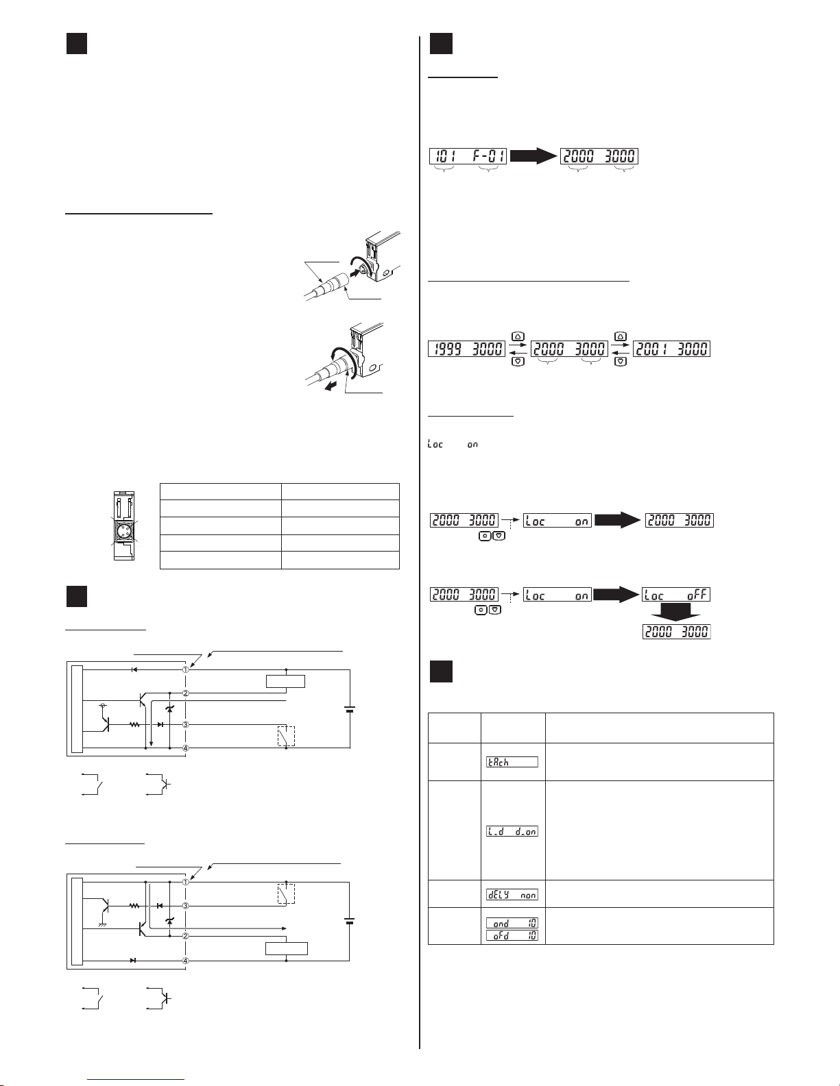
I/o cIrcuIt DIaGraMs
NPN output type
+
–
8V
*
±10%
Main circuit
100mA max.
(Brown) +V
(Black) Output
(Blue) 0V
(White) External input
Color code of cable with connector
Load
Connector pin No.
12 to 24V DC
* Non-voltage contact or NPN open-collector transistor
or
● High (+8V to +V DC or Open): Invalid
● Low [(0 to +2V DC (source current 0.5mA or less)]: Valid
PNP output type
*
+
–
±10%
Main circuit
100mA max.
(Brown) +V
(Black) Output
(Blue) 0V
(White) External input
Color code of cable with connector
12 to 24V DC
Load
Connector pin No.
* Non-voltage contact or PNP open-collector transistor
or
● High [+4V to +V DC (Sink current 0.5 to 3mA or less)]: Valid
● Low (0 to +0.6V DC or Open): Invalid
6
run MoDE
Digital display
When you turn ON the power, the product name is indicated in green and
the emission frequency is indicated in red. Then the device automatically
switches into RUN mode, in which the threshold value is displayed in green
and the incident light intensity in red.
Power ON
Emission
frequency
Product
name
RUN mode
Incident light
intensity
Threshold
value
Automatic
* What appears on the display is effected by the settings for the
external input and ECO mode. For details, see PRO MODE on
page 4.
Threshold value ne adjustment function
Change the threshold value in RUN mode by pressing <UP> or <DOWN>.
Hold down the key to make the value change faster. The threshold value is
stored after 3s.
RUN mode
Incident light
intensity
Threshold
value
Key lock function
The key lock function prevents settings from being changed inadvertently.
is displayed if you press a key when the key lock function is set.
Press <MODE> + <DOWN> for at least 2s to set or release the key lock
function.
Set key lock
RUN mode
Press for 2 sec.
Automatic
Release key lock
RUN mode
Press for 2 seconds
Automatic
Automatic
7
sEttInG MoDE
To enter SETTING mode, press <MODE> for 2s in RUN mode. While in
SETTING mode, press <MODE> briey to move from one selection to the
Item
Factory setting
Description
Teaching
A threshold value can be set in 2-point teaching, limit
teaching or full-auto teaching.
For details, see tEacHInG MoDE on page 7.
Output
operation
Light-ON or Dark-ON can be set.
● light-on means the output will turn ON when
the incident light intensity is in the brighter of
the two 2 sensing states (object present/object
absent).
● Dark-ON means the output will turn ON when
the incident light intensity is in the darker of
the two 2 sensing states (object present/object
absent).
Timer
selection
Three settings are possible: no timer, ON delay timer,
or OFF delay timer.
Timer
delay
You can specify the delay for the ON delay timer or
OFF delay timer.
If no timer is set, this mode is not displayed.
3
Item
Factory setting
Description
Emission
level
If the incident light intensity is saturated, which makes
sensing impossible or unreliable, you can reduce the
emission level.
● Level 3 (
): Normal
● Level 2 (
): Approx. 40% of normal
● Level 1 (
): Approx. 20% of normal
When you select Auto (
), proper light intensity is
automatically set only during limit teaching.
* For differences between the conventional and
modied units, see unIt VErsIons on page
7.
Emission
frequency
FX-102□-Z
FX-101□-Z
When using ber heads in parallel, interference can be
prevented by setting different emission frequencies.
When emission frequency 0 is set, interference cannot
be prevented. Response time corresponds to emission
frequency. For details, see sPEcIFIcatIons on
page 8.
Flowchart for sEttInG mode
run mode
Press for 2s.
sEttInG mode
Automatic
teaching
output operation
Light-ONDark-ON
timer operation
1, 5, 10, 20, 40, 50, 100, 500, 1000ms
:
Without timer
Timer delay Timer delay
Timer delays setting mode Timer delays setting mode
ON delay timer
OFF delay
timer
Timer delays available (ms):
Emission level
Level 2Level 3 Auto + Level 3Level 1
Emission frequency
FX-101□-Z FX-102□-Z
FX-101□-Z
FX-102□-Z
Emission
frequency 0
Emission
frequency 1
Emission frequencies available:
Emission frequencies available:
* The operation indicator and the beam-emitting inlet blink while the
emission frequency is being set. When the emission frequency is
set to 0, they light up. The blinking cycle depends on each emission
frequency (emission frequency 1: fast ↔ emission frequency 4:
slow).
run mode
8
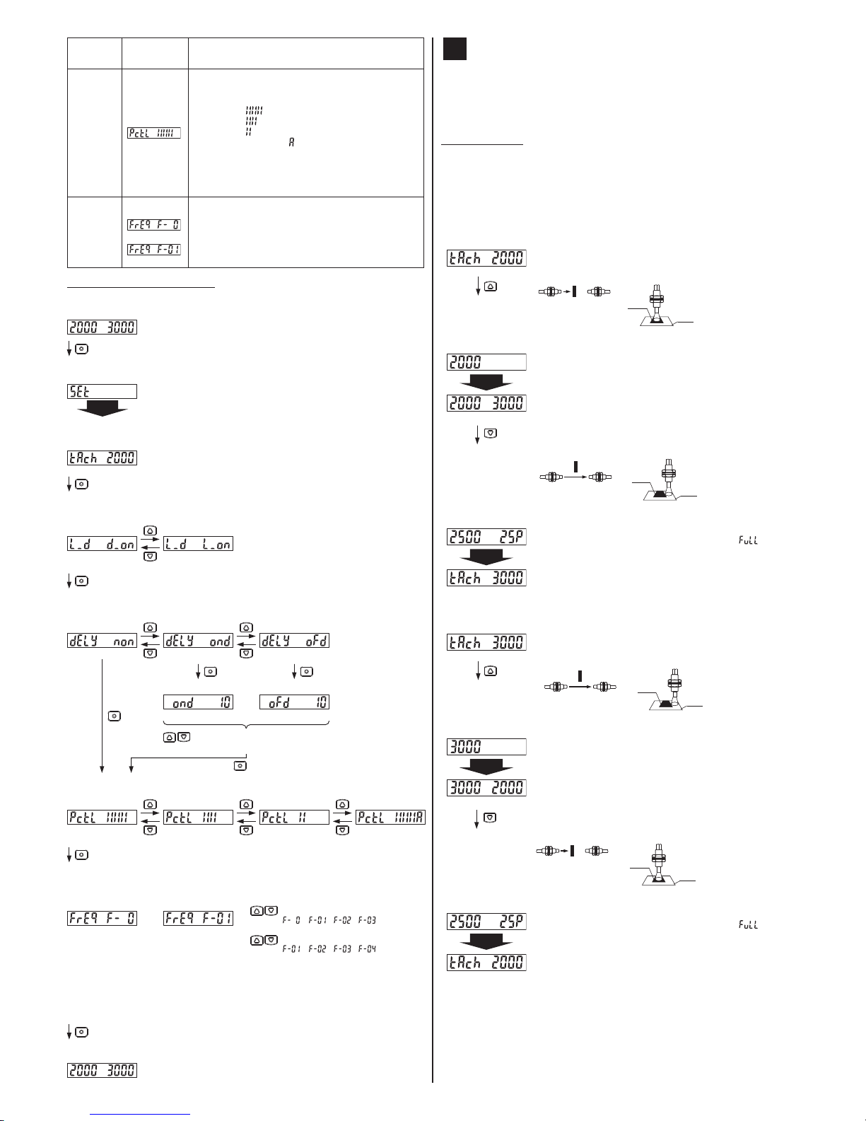
tEacHInG MoDE
* Beware that detection may become unstable if too little margin
between the theshold value and incident light intensity is allowed for the environment when teaching.
2-point teaching
2-point teaching is the most common teaching method and means the
threshold value is taught using two points that correspond to the object
present and object absent conditions.
Light-ON or Dark-ON is determined automatically for the output operation
setting.
Output indicator ON when object is present
In teaching mode, press <ON> when object is present to set
the rst incident light intensity.
Thru-beam type
Light interrupted
condition
Light received condition
Mark
Reflective type
Base
Automatic
The rst incident light intensity is set and is displayed in
green. The red LED display blinks and is ready to be set to
the object absent condition.
To cancel, press <MODE>.
Remove the object and press <OFF> to complete 2-point
teaching.
Thru-beam type
Light received condition
Light interrupted condition
Mark
Reflective type
Base
Automatic
The margin between the rst and second incident is displayed
in red (P=%). When the margin is 200% or more,
is
displayed.
Output indicator ON when object is absent
In teaching mode, press <ON> when object is absent to set
the rst incident light intensity.
Thru-beam type
Light received condition
Light interrupted condition
Mark
Reflective type
Base
Automatic
The rst incident light intensity is set and is displayed in
green. The red LED display blinks and is ready to be set to
the object present condition.
To cancel, press <MODE>.
Place the object so that it is sensed and press <OFF> to
complete 2-point teaching.
Thru-beam type
Light interrupted
condition
Light received condition
Mark
Reflective type
Base
Automatic
The margin between the rst and second incident is displayed
in red (P=%). When the margin is 200% or more,
is
displayed.
 Loading...