

Panasonic FV-11VKL3, FV-11VK3 service manual
PEG1111029CE
Version:1302
Service Manual
Ceiling Mount Ventilating Fan
TM
Whisper Green
(North America Market)
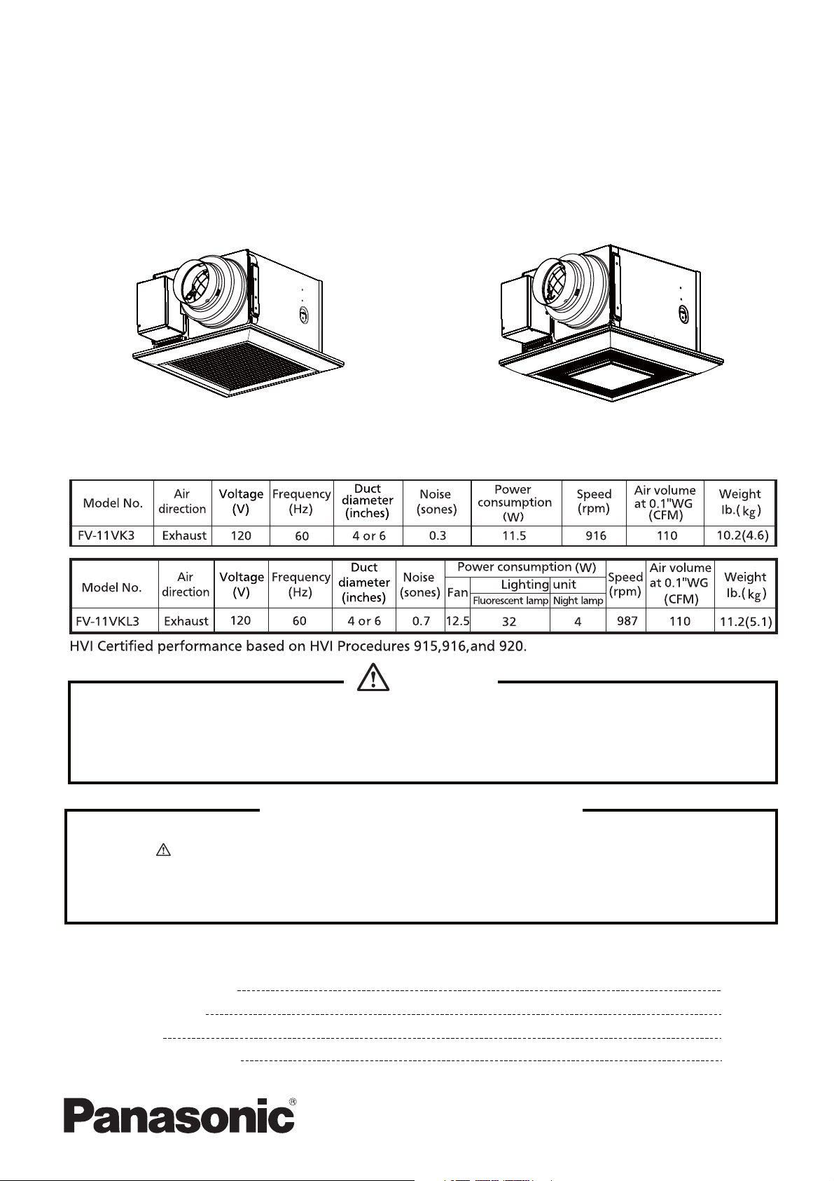
FV-11VK3
FV-11VKL3
Specifications
WARNING
This service information is designed for experienced repair technicians only and is not designed for use by
the general public. It does not contain warnings or cautions to advise non-technical individuals of potential
dangers in attempting to service a product. Products powered by electricity should be serviced or repaired
only by experienced professional technicians. Any attempt to service or repair the product or products dealt
with in this service information by anyone else could result in serious injury or death.
IMPORTANT SAFETY NOTICE
There are special components used in this equipment which are important for safety. These parts are
marked by in the Schematic Diagrams, Exploded Views and Replacement Parts List. It is essential
that these critical parts should be replaced with manufacturer's specified parts to prevent shock, fire
or other hazards. Do not modify the original design without permission of manufacture.
We suggest to handle such parts after the static electricity prevention.
It is forbidden to touch the PCB parts by bare hands during the repairing process.
CONTENTS
1. Parts Identification
2.Wiring Diagram
3. Parts List
4. Replacement Guide
PAGE
1~4
5
6~9
10~12
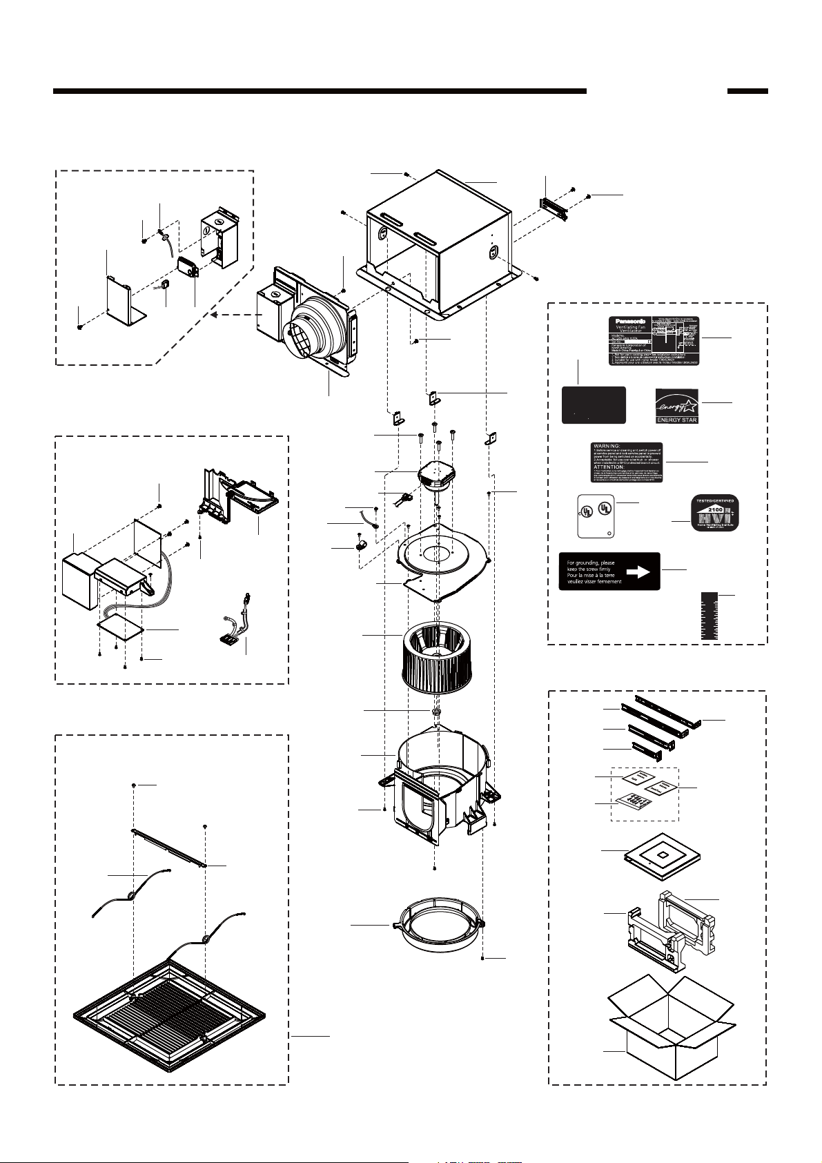
1.Parts Identification
Main Body Section
B
6
C
(3pcs)
FV-11VK3
1
2
A
(2pcs)
7
A
4
5
Details Of Wiring Section
F
(4pcs)
18
E
(2pcs)
19
F
(4pcs)
Main PCB Section
G
(2pcs)
20
17
(20)
11
A
3
C
13
14
15
(3pcs)
D
(4pcs)
9
10
12
B
A
FV-11VK3
24
25
8
(3pcs)
CAUTION:
To reduce the risk of injury to persons,install fan at least
2.1m(7feet)above the floor.
ATTENTION:
Afin de reduire les risques de blessures corporelles,
Installer le ventilateur a au moins 2,1m(7 pieds)du sol.
26
27
E
(5pcs)
LISTEN
A375682G8
US
FAN
8B68
28
C
29
30
mm
Inch
31
1
_
2
2
60
2
50
40
1
_
1
2
30
1
20
1
_
2
10
Main Labels
(Stuck On Frame Assembly)
33
34
32
35
36
37
38
22
(2pcs)
Grille Unit
21
39
40
41
16
E
23
42
Main Packing Materials
1
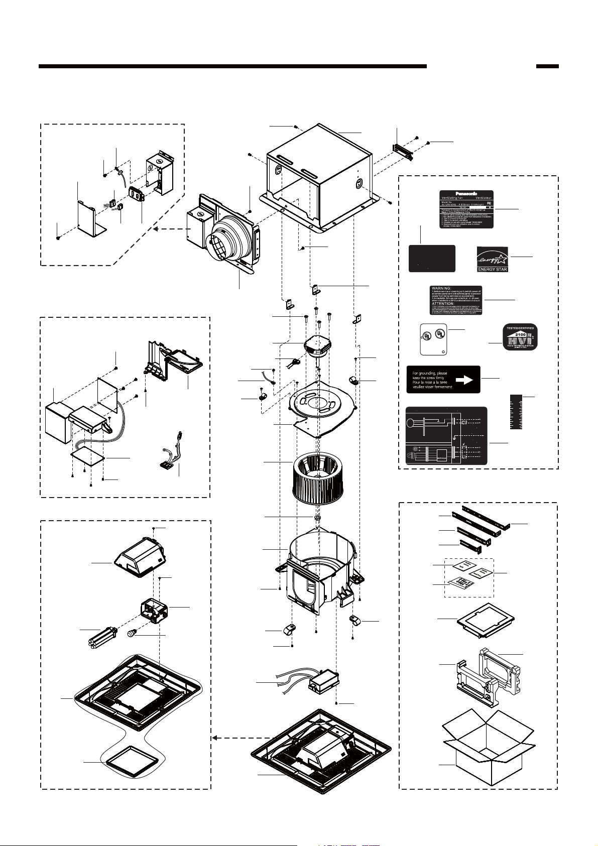
1.Parts Identification
Main Body Section
B
6
C
(3pcs)
FV-11VKL3
1
2
A
(2pcs)
7
5
A
3
4
Details Of Wiring Section
F
(4pcs)
22
E
(2pcs)
21
F
(4pcs)
Main PCB Section
G
23
25
26
19
E
20
24
(19)
12
11
C
(3pcs)
A
(4pcs)
15
16
17
B
12
(2pcs)
D
9
10
13
E
FV-11VKL3
29
30
A
CAUTION:
To reduce the risk of injury to persons,install fan at least
2.1m(7feet)above the floor.
ATTENTION:
Afin de reduire les risques de blessures corporelles,
Installer le ventilateur a au moins 2,1m(7 pieds)du sol.
31
8
(3pcs)
LISTEN
A375682G8
US
FAN
8B68
33
C
34
32
E
(5pcs)
()
VENT.
(Power supply/
Alimentation
electrique)
(Power supply/
Alimentation
electrique)
()
N.LIGHT
()
LIGHT
35
mm
Inch
36
1
_
2
2
60
2
50
40
1
_
1
2
AC120V
60Hz/
120V CA
60Hz
AC120V
60Hz/
120V CA
60Hz
AC120V
60Hz/
120V CA
60Hz
30
20
10
37
1
1
_
2
12
Fan body/Boite du ventilateur
Main control circuit/
Circuit de commande principal
Black/Noir
DC-
White/Blanc
Motor/
DC-
Blue/Bleu
Moteur
Red/Rouge
Lighting unit/Appareil d eclairage
Black/Noir
Night
lamp/
White/Blanc
Veilleuse
Blue/Bleu
Blue/Bleu
Flourescent
lamp/Ampoule flourescente
Wiring diagram/Schema de connexions
Junction box/Boite de raccordement
Green/Vert
White/Blanc
Black/Noir
Black/Noir
White/Blanc
White/
Blanc
Electronic
Blue/Bleu
ballast/
Black/
Blue/Bleu
Ballast
Noir
Red/RougeRed/Rouge
Red/RougeRed/Rouge
Neutral/
White/
Neutre
Blanc
Live/Sous
Black/
tension
Noir
ON
Switch box/Boite
de commutation
(Earth ground/
Green/
Mise a la terre)
Vert
Switch box/Boite
de commutation
Live/Sous
Black/
tension
Noir
ON
Neutral/
White/
Neutre
Blanc
Black/
Live/Sous
tension
Noir
ON
Main Labels
(Stuck On Frame Assembly)
39
40
38
41
42
43
44
14
45
46
47
27
28
Grille Unit
18
E
48
49
Main Packing Materials
2
1.Parts Identification
Model Part No. Part Name
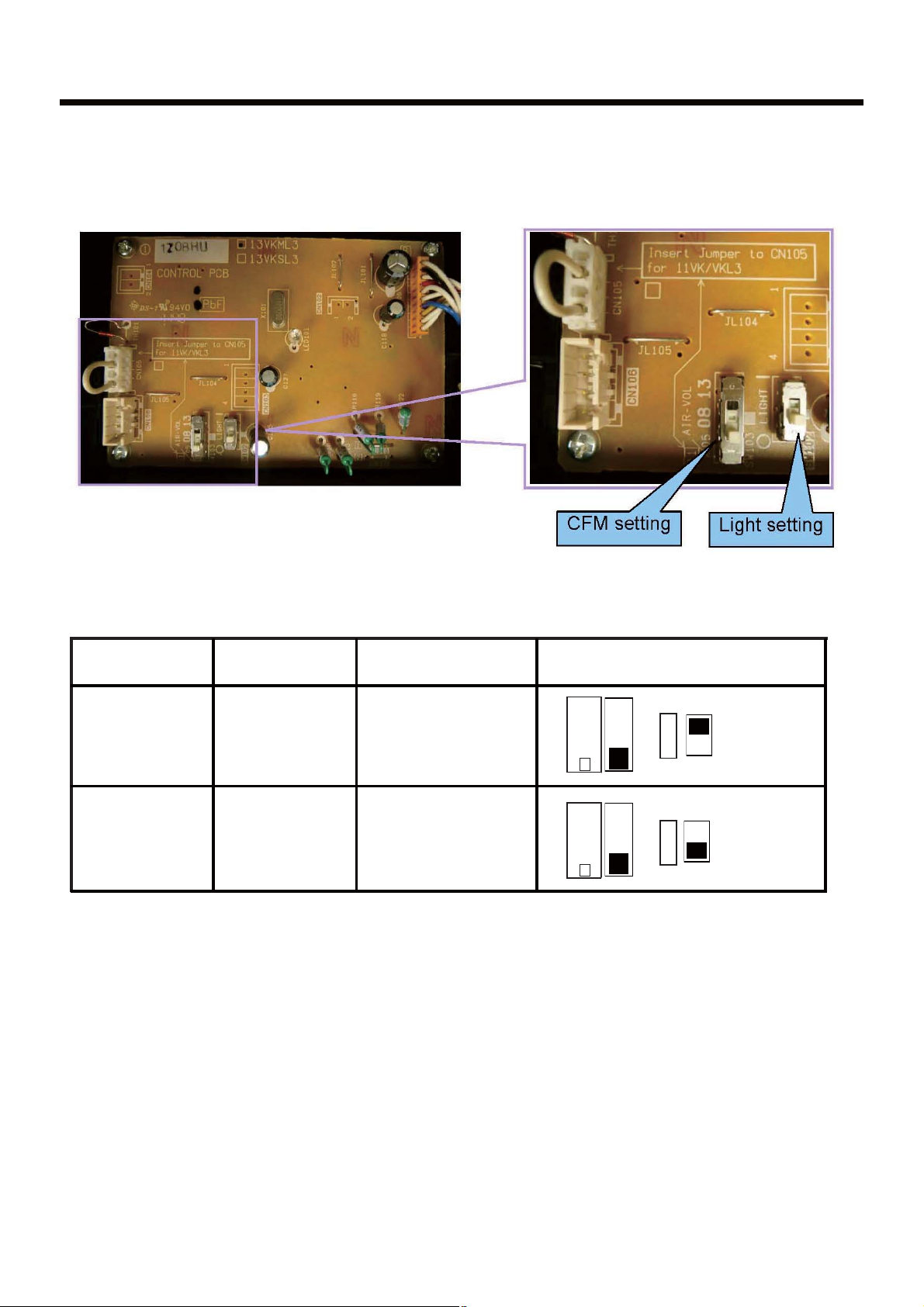
Switch seting condition for PCB
(SW103、SW102)
FV-11VK3 FFV3740024S Main PCB Assembly
FV-11VKL3 FFV3740024S Main PCB Assembly
Replace Main PCB Assembly
The main PCB assembly is commonly used in below models.If you replace PCB,please
set up the switch according to below table firstly.
LIGHT
AIR-VOL
/05 08 13
11
AIR-VOL
/05 08 13
11
0 I
LIGHT
0 I
3
 Loading...