

Page 1
(For Contractor Pack)
Housing Can
FV-05-11VFA2
Motor/Grille Assembly
FV-05VFB2
Applicable to Models: FV-05VF2, FV-08VF2, FV-11VF2
READ AND SAVE THESE INSTRUCTIOINS.
Please
operate or service the Panasonic Ventilating Fan. Failure to comply
with instructions could result in personal injury and/or property
damage. Please retain this booklet for future reference.
read
these
instructions
carefully
before
FV-08VFB2, FV-11VFB2
attempting
install,
to
Table of Contents
General Safety Information
Unpacking
Supplied Accessories
Wiring diagram
Installation
Installation
Installation
Installation
Installation
Installation
Product Service
I
( Joist Mounting- )I
( Joist Mounting- )II
II
III
( -Joist Mounting )I
IV
( Between Joist Mounting )
V
( Wooden Header )
VI
( In Existing Construction )
2
2
3
3
4-5
6-7
7
8-9
9
10
10
Page 2
GENERAL SAFETY INFORMATION
1. Do not install this ventilating fan where air temperature may exceed 40 C (104 F).
2. Make sure that the electric service supply voltage is 120 V, 60 Hz.
3. Follow all local electrical and safety codes, as well as the National Electrical Code (NEC) and the Occupation
Safety and Health Act (OSHA).
4. Always disconnect the power source before working on or near the fan, motor or junction box.
5. Protect the power cord from sharp edges, oil, grease, hot surfaces, chemicals or other objects.
6. Do not kink the power cord.
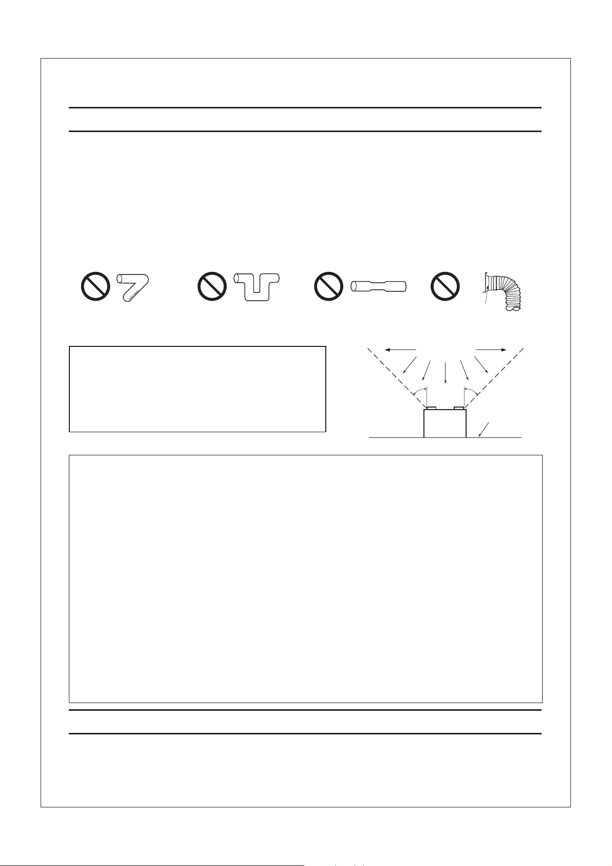
7. Do not install the unit where ducts are configured as shown in Fig. A.
8. Provide suction parts with proper ventilation.
9. This unit is UL listed for use over a bathtub or shower when installed in a GFCI protected branch circuit.
oo
Prohibition
Prohibition Prohibition Prohibition
Adaptor
Fig. A
(Cooking area)
Do not install above or
inside this area
CAUTION:
1. For general ventilating use only. Do not use to exhaust
hazardous or explosive materials and vapors.
o
45
45
o
2. Not for use in cooking area. (Fig .B)
3. This product must be properly grounded.
Cooking
equipment
Floor
Fig. B
WARNING:
To reduce the risk of fire, electric shock or injury to persons, observe the following:
A. Use this unit only in the manner intended by the manufacturer. If you have any questions, please contact to the manufacturer.
B. Installation work and electrical wiring must be done by qualified person(s) in accordance with all applicable
codes and standards, including fire-rated construction.
C. Sufficient air is needed for proper combustion and exhausting of gases through the flue (chimney) of fuel burning
equipment to prevent backdrafting. Follow the heating equipment manufacturer's guideline and safety standards
such as those published by the National Fire Protection Association (NFPA), and the American Society for Heating
Refrigeration and Air Conditioning Engineers (ASHRAE) and the local code authorities.
D. The Housing Can FV-05-11VFA2 must be installed with Motor/Grille Assembly FV-05/08/11VFB2 only.
E. When cutting or drilling into wall or ceiling, do not damage electrical wiring and other hidden utilities.
F. Ducted fans must always be vented to the outdoors.
G. These models are UL listed for tub and shower enclosures.
H. Solid state controls may cause harmonic distortion which can cause motor humming noise. To reduce the risk of
fire or electric shock, do not use this unit with any solid-state control device.
I. Before servicing or cleaning unit, switch power off at service panel and lock the service disconnecting
means to prevent power from being switched on accidentally. When the service disconnecting means
cannot be locked, securely fasten a prominent warning device, such as a tag, to the service panel.
J. NEVER place a switch where it can be reached from a tub or shower.
K. Not to be installed in a ceiling thermally insulated to a value greater than R40. (This is required for installation
in Canada only.)
UNPACKING
Unpack and carefully remove unit from carton.
Refer to the following Supplied Accessories list to verify that all parts are present.
2
Page 3
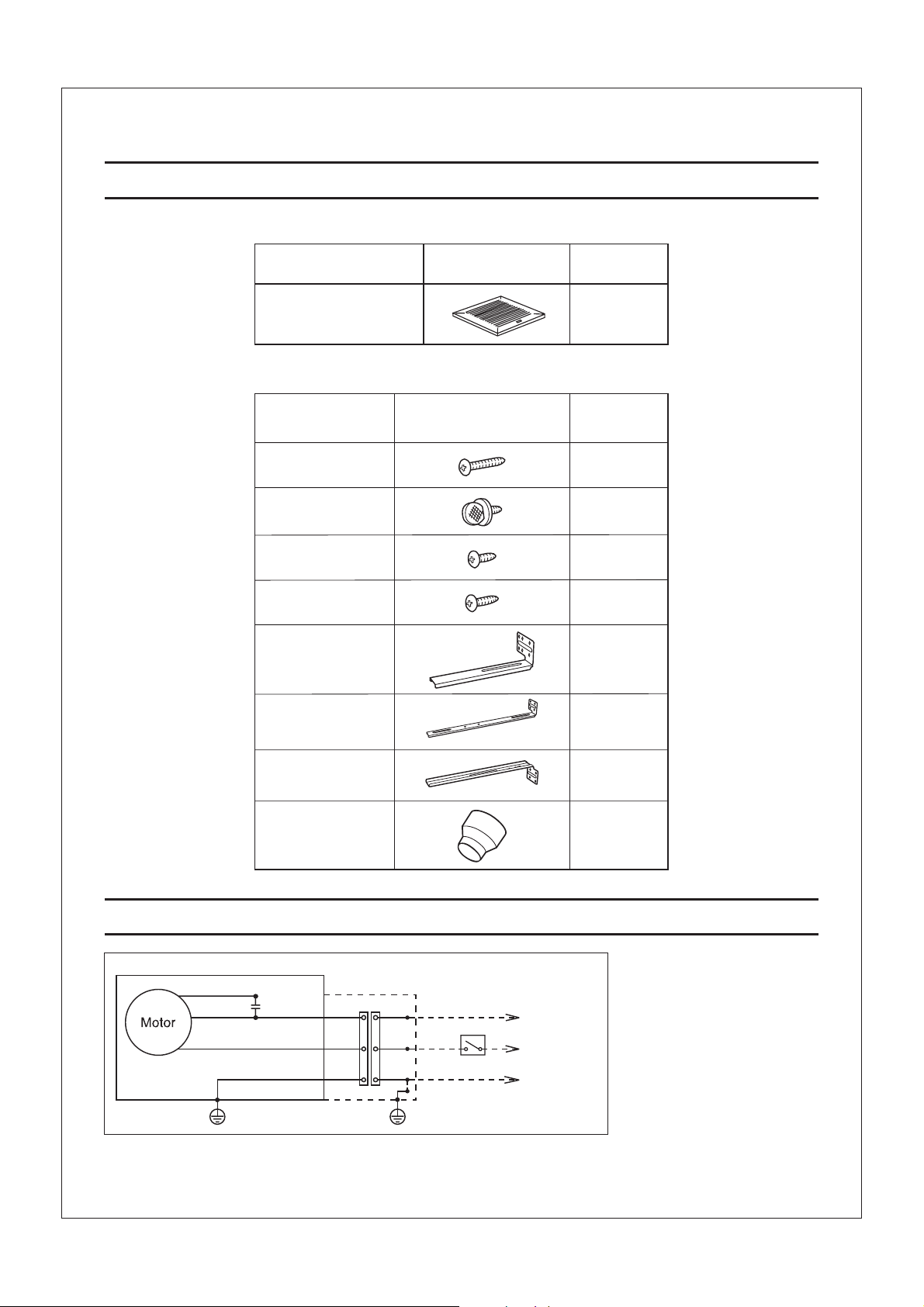
SUPPLIED ACCESSORIES SETS(4 )SUPPLIED ACCESSORIES SETS(4 )
(A) For Motor / Grille Assembly of model: FV-05/08/11VFB2
Part name
Grille
Appearance
(B) For Housing Can of model: FV-05-11VFA2
Part name
Long screw
(ST4.2X20)
Thumb screw
Screw
I
(ST4.2X8)
Screw
II
(ST4.2X10)
Suspension
bracket I
Suspension
bracket II
Appearance
Quantity
4
Quantity
24
4
8
8
4
4
Suspension
bracket III
3 inches adaptor
connector
(optional part)
WIRING DIAGRAM
Fan body
Red
White
Black
Capacitor
Green Green
Earth ground
Junction box
White White
Black
Green
Neutral
Switch
(not included)
LiveBlack
Earth ground
Earth ground
3
4
4
OFF
ON
Power Supply
AC120V 60Hz
Page 4
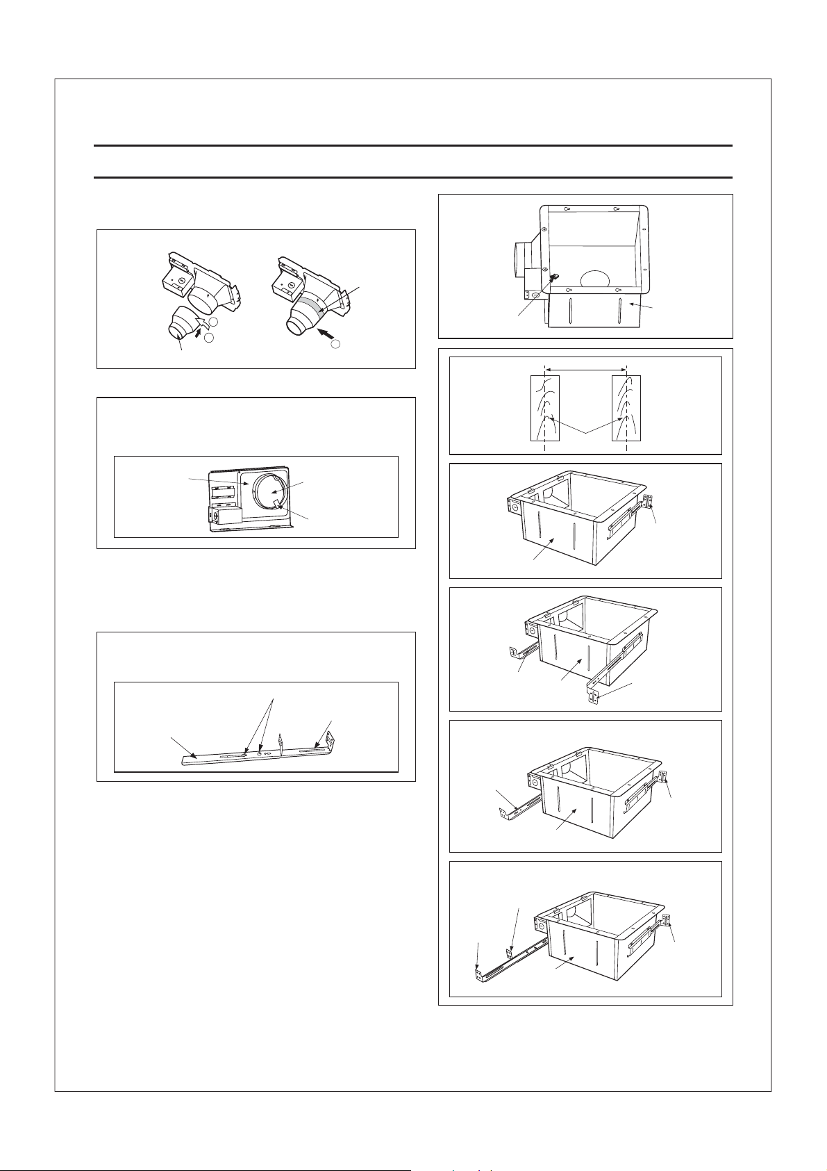
INSTALLATION JOIST MOUNTING-II()INSTALLATION JOIST MOUNTING-II()
1. Before installation, Secure the fan body to adaptor by
using thumb screw. (Fig. 1)
Connection method for 3 inches adaptor connector
Duct tape
2
1
3 inches adaptor connector
3
IMPORTANT:
Remove the tape from damper and adaptor
before installation.As shown below:
Adaptor
2. Insert the suspension bracket into the fan body and
adaptor. (select the suspension bracket acc rding
to Fig. 2)
If spacing A on center joists is 24 inches, connect
suspension bracket and (C4 mark to C4 mark)
II III
as shown below :
2 Screw (ST4.2X8)I
Suspension bracket III
Damper
Tape
o
Suspension bracket II
Thumb screw
A = 12 inches
Fan body
A = 16 inches
Suspension
bracket I
A = 19.2 inches vertical joists
Fan body
Fan body
Fig. 1
A
Joists
Suspension
bracket I
Fig. 2-1
Suspension
bracket III
Fig. 2-2
Suspension
bracket III
Suspension
bracket I
Fan body
A = 24 inches
Suspension
bracket III
Suspension
bracket II
Fan body
Fig. 2-3
Suspension
bracket I
Fig. 2-4
4
Page 5

INSTALLATION JOIST MOUNTING-II( ) CONTINUEDINSTALLATION JOIST MOUNTING-II( ) CONTINUED
3. Install the suspension bracket and the flange of fan body
to joists by using long screws (ST4.2X20) according to
Fig. 3.
4. Install the suspension bracket to joists by using long
screws (ST4.2X20) and secure it to the fan body by
using screw (ST4.2X10) (Fig. 4)II
5. Remove junction box cover and secure conduit or
stress relief to junction box knock-out hole. (Fig. 5)
Others
Joist
Fan body
A = 10 1/4~12 inches
Fan body
2 Long screws
(ST4.2X20)
4 Long screws (ST4.2X20)
Screw (ST4.2X10)II
Fig. 3-1
Joist
2 Long screws
(ST4.2X20)
Fig. 3-2
Joist
Fig. 4
6. Refer to wiring diagram (page 3).
Using wire nuts, connect house power wires to
ventilating fan wires:
black to black; white to white; green to green;
Replace the junction box cover. (Fig. 5)
CAUTION:
Mount junction box cover carefully so that lead
wires are not pinched.
7. Install a duct and secure it with duct tape
or clamps.
8. Finish ceiling work. Ceiling hole should be aligned
with the edge of the flange. (Fig. 6)
9. Follow the Fig. 12-3, 12-4 (page 9) and Fig. 7 (page 8)
of the original installation instruction to complete the
motor/grille assembly installation.
Junction box cover
Junction box
Lead wires
Ceiling
inches (mm)
Conduit
Conduit
Green wires
10 7/8
Duct
Duct tape
Joist
Wire nut
Fig. 5
(275)
10 7/8
(275)
Fig. 6
5
Page 6

INSTALLATION JOIST MOUNTING-II II()INSTALLATION JOIST MOUNTING-II II()
1. Remove adaptor from fan body before starting
installation.
Adaptor
2. Insert the suspension bracket into the adaptor and
secure it to joists by using long screws (ST4.2X20)
(Fig. 7)
Keep the distance B (7/8 inch, 21.6mm) for the
thickness of ceiling board.
If spacing A between joists is 21 1/4 to 23 1/2
inches, connect suspension bracket and
II III
(C4 mark to C4 mark) according to page 4
Select the suspension bracket according to
spacing A as shown below.
Spacing A
between Joists
inches (mm)
suspension
bracket
3. Follow step 5 to 7 of the Installation (page 5) to
13 1/4~15 1/2
( 336~394 )
suspension
bracket I
16 1/2~18 3/4
( 419~480 )
suspension
bracket III
21 1/4~23 1/2
( 540~597 )
suspension
bracket &II III
I
complete the duct work and wiring.
4. Insert to fan body
the suspension bracket in
(refering to step 2 of Installation , page 4)
I
2 Long screws
(ST4.2X20)
2 Long screws
(ST4.2X20)
inches mm()
13 1/4~15 1/2 ( 336~394 )
16 1/2~18 3/4 ( 419~480 )
21 1/4~23 1/2 ( 540~597 )
B
7/8 (21.6)
Joists
Adaptor
A
Fig. 7
5. Insert the fan body into joists. (Fig. 8)
IMPORTANT:
Make sure that adaptor claws are properly inserted
into fan body slots.
Joist
Junction box cover
Adaptor
claws
Duct
Conduit
Fan body
Slots
Duct tape
Fig. 8
6
Page 7

INSTALLATION JOIST MOUNTING-II II( ) CONTINUEDINSTALLATION JOIST MOUNTING-II II( ) CONTINUED
6. Secure the fan body to adaptor by using thumb
screw (Fig. 9)
7. Secure to joists by using
long screws (ST4.2X20) and secure it to fan body
by using screw (ST4.2X10) in vertical direction
the suspension bracket
II
Receptacle
(Fig. 9)
8. Follow step 8~9 of Installation (page 5) to
I
complete the installation work.
2 Long screws
(ST4.2X20)
Screw
(ST4.2X10)
II
Thumb
screw
INSTALLATION JOIST MOUNTINGIII I-()INSTALLATION JOIST MOUNTINGIII I-()
4 kinds of -joist
inches (mm)
C1
C2
C
C3
C4
C3
I
9/16 ( )14.3
11/16 (17.5)
31/32 (24.6)
1 17/32 38.9()
Suspension
bracket III
Screw (ST4.2X10)II
Fig. 9
C4
C1
C2
Suspension bracket
The suspension can comply with
different kinds of -joist.
III
bracket
I
III
1. Before installation, secure the fan body to adaptor by
using thumb screw. (Fig. 1 of page 4)
2. Connect the suspension to fan body. (Fig. 10)
(select the hole by checking joist size fix the screw
bracket III
I-
to the frame hole.)
3. Connect the fan body to the joist. (Fig. 11)I-
4. Follow step 5 to 9 of installation (page 5) to complete
I
the installation work.
7
I joist
4 Long screws
(ST4.2X20)
Fig. 10
Fig. 11
Page 8

INSTALLATION BETWEEN JOIST MOUNTINGIV ()INSTALLATION BETWEEN JOIST MOUNTINGIV ()
1. Before installation, secure the fan body to adaptor
by using thumb screw. (Fig.1 of page 4)
2. Insert the suspension bracket into the bracket cover of
adaptor side and the back of the fan body. (Fig.12)
(select the suspension bracket according to spacing A
as shown below)
A = 16 inches and 19.2 inches horizontal joist
Suspension bracket I
A
16 inches and 19.2
inches horizontal joist
and
19.2 inches vertical joist
3. Insert the fan body between joists.
Make sure the fan body is level and square
(perpendicular)with the joists.(Fig. 13)
Keep the distance B (7/8 inch, 21.6mm) for the
thickness of ceiling board.
Suspension bracket III
A = 19.2 inches vertical joist
Suspension bracket III
Suspension bracket II
Suspension bracket II
Fig.12-1
Suspension bracket I
Fig.12-2
Joists
Adaptor
8
Fan body
inches mm()
13 1/4~15 3/4 ( 336~400 )
16 1/2~18 3/4 ( 419~480 )
3~5 ( 76~126 )
5 4/5~7 4/5 ( 148~198 )
B
7/8 (21.6)
Junction box
A
Fig. 13
Page 9

INSTALLATION BETWEEN JOIST MOUNTINGIV ( ) CONTINUEDINSTALLATION BETWEEN JOIST MOUNTINGIV ( ) CONTINUED
4. Secure the suspension bracket to joists by using long
screws (ST4.2X20) (Fig. 14, Fig. 15)
2 Long screws (ST4.2X20)
5. Secure the suspension bracket to fan body by using
screw (ST4.2X10) (Fig. 15)II
II
4 Long screws
(ST4.2X20)
6. Follow step 5 to 9 of installation (page 5) to complete
I
2 Screw
(ST4.2X10)
the installation work.
INSTALLATION WOODEN HEADEV (R)INSTALLATION WOODEN HEADEV (R)
1. Before installation, secure the fan body to adaptor by
using thumb screw. (Fig. 1 of page 4)
2. Install header between joists by using nails or screws.
3. Install the fan body and secure it by using long
screws (ST4.2X20) (Fig. 16 of page 8, Fig. 17)
4. Follow step 5 to 9 of installation (page 5) to complete
I
the installation work.
inches (mm)
Joist
(275)
Fan body
10 7/8
14 3/4
(375)
Fig. 14
Joist
Fig. 15
Header
Joist
Adaptor
Fig. 16
Duct
Adaptor
6 Long screws
(ST4.2X20)
Junction box
Lead wires
Green wires
Conduit
Wire nut
Fig. 17
9
Page 10

INSTALLATION IN EXISTING CONST UCTIONVI (R)INSTALLATION IN EXISTING CONST UCTIONVI (R)
1. Installation in existing construction.
Installing the ventilating fan in an existing building requires an accessible area (attic or crawl space) above
the planning installation location or existing ducting and wiring.
(1) To install the ventilating fan, follow the procedures described in lnstallation . Take the following
precautions before installation.
II
CAUTION:
Check area above planning installation location to be sure that:
1. Duct work can be installed and that area is sufficient for proper ventilation.
2. Wiring can be run to planning location.
3. No wiring or other obstructions shall interfere with installation.
(2) Inspect duct work and wiring before proceeding with installation.
(3) Plan suitable location for ventilating fan. (next to ceiling joist)
(4) Before installation, provide inspection and maintenance access at a location that will not interfere
with installation work shown in installation .II
(5) First, remove ceiling section according to Fig. 6 of page 5.
(6) Install ventilating fan.
2. Installation from accessible area above fan location.
(1) Inspect duct work and wiring before proceeding with installation.
(2) Remove ceiling section according to Fig. 6 of page 5.
(3) Install ventilating fan.
P ODUCT SE VICERRP ODUCT SE VICERR
Warning Concerning Removal of Covers.
The unit should be serviced by qualified technicians only. No service information is provided for customers.
Your product is designed and manufactured to ensure a minimum of maintenance. However, should your
unit ever require service, a nationwide system of factory service centers and AUTHORIZED INDEPENDENT
SERVICE CENTERS is maintained to support your product's warranty.
(In the U.S.A.,call 1-866-292-7292 to Customer call center.)
10
Page 11

PANASONIC CONSUMER ELECTRONICS COMPANY
Division of Panasonic Corporation of North America,
One Panasonic Way, Secaucus, NJ 07094
PANASONIC CANADA INC.
5770 Ambler Driver, Mississauga, ON L4W 2T3
www.panasonic.com
X0206-2047 08VFA2420B
 Loading...