

Panasonic fv0511vk1, fv1115vk1, fv0511vks1 installation
Contents
Model No.
FV-05-11VKS1
FV-05-11VK1
FV-11-15VK1
FV-05-11VKS1 FV-05-11VK1
FV-11-15VK1
GENERAL SAFETY INFORMATION
PLEASE READ PRIOR TO INSTALLING THIS FAN
DESCRIPTION
UNPACKING
SUPPLIED ACCESSORIES
DIMENSIONS
WIRING DIAGRAM
FEATURE
INDICATION (PLUG ‘N PLAY FUNCTION DEVICES)
DESCRIPTION FOR NIGHT LIGHT MODULE
MOTION (PLUG ‘N PLAY FUNCTION DEVICES)
INSTALLATION (PLUG ‘N PLAY FUNCTION DEVICES)
INSTALLATION (NEW CONSTRUCTION)
INSTALLATION (RETROFIT)
MAINTENANCE (CLEANING)
PRACTICAL GUIDE TO INSTALLATION
SPECIFICATIONS
PRODUCT SERVICE
BACK COVER
BACK COVER
BACK COVER
2-3
4
4
4
5
5
5
5-6
6-7
7
7
8
8-10
10
11
Thank you for purchasing this Panasonic product.
For Your Safety
To reduce the risk of injury, loss of life, electric shock, fire, malfunction, and damage to
equipment or property, always observe the following safety precautions.
Explanation of symbol word panels
The following symbol word panels are used to classify and describe the level of hazard, injury, and
property damage caused when the denotation is disregarded and improper use is performed.
WARNING
CAUTION
The following symbols are used to classify and describe the type of instructions to be observed.
This symbol is used to alert users to a specific operating procedure that must be followed
in order to operate the unit safely.
This symbol is used to alert users to a specific operating procedure that must not be
performed.
This symbol is used to alert users not to disassemble the equipment.
This symbol is used to alert users to make sure of grounding when using the equipment
with the grounding terminal.
WARNING
WARNING
To reduce the risk of fire, electric shock or injury to persons, observe the following :
Use this unit only in the manner intended by the manufacturer. If you have any questions,
contact the manufacturer.
Before servicing or cleaning unit, switch power off at service panel and lock the service
disconnecting means to prevent power from being switched on accidentally. When the
service disconnecting means cannot be locked, securely fasten a prominent warning device,
such as a tag, to the service panel.
Installation work and electrical wiring must be done by qualified person(s) in accordance with
all applicable codes and standards, including fire-rated construction.
Denotes a potential hazard that could result in serious
injury or death.
Denotes a hazard that could result in minor injury.
When cutting or drilling into wall or ceiling, do not damage electrical wiring and other
hidden utilities.
Ducted fans must always be vented to the outdoors.
If this unit is to be installed over a tub or shower, it must be marked as appropriate for the
application and be connected to a GFCI(Ground Fault Circuit Interrupter) - protected branch
circuit.
These models are UL listed for tub and shower enclosures.
2
WARNING
Canada only: Not to be installed in a ceiling thermally insulated to a value greater than R40.
Do not disassemble the unit for reconstruction. It may cause fire or electric shock.
When this product is no longer being operated, please remove the product to prevent the
possibility of falling.
Ceiling joist must be subjected to static load more than five times the weight of the product.
Do not install with a method which is not approved in the instructions.
Do not use this fan with any solid-state speed control device. Solid state controls may cause
harmonic distortion which can cause motor humming noise.
This product must be properly grounded.
CAUTION
Do not install this ventilating fan where interior room temperature may
exceed 104°F(40°C).
Make sure that the electric service supply voltage is AC 120V, 60Hz.
Follow all local electrical and safety codes, as well as the National
Electrical Code (NEC) and the Occupation Safety and Health Act (OSHA).
Always disconnect the power source before working on or near the fan,
motor or junction box.
Protect the supply wiring from sharp edges, oil, grease, hot surfaces,
chemicals or other objects.
Do not kink the supply wiring.
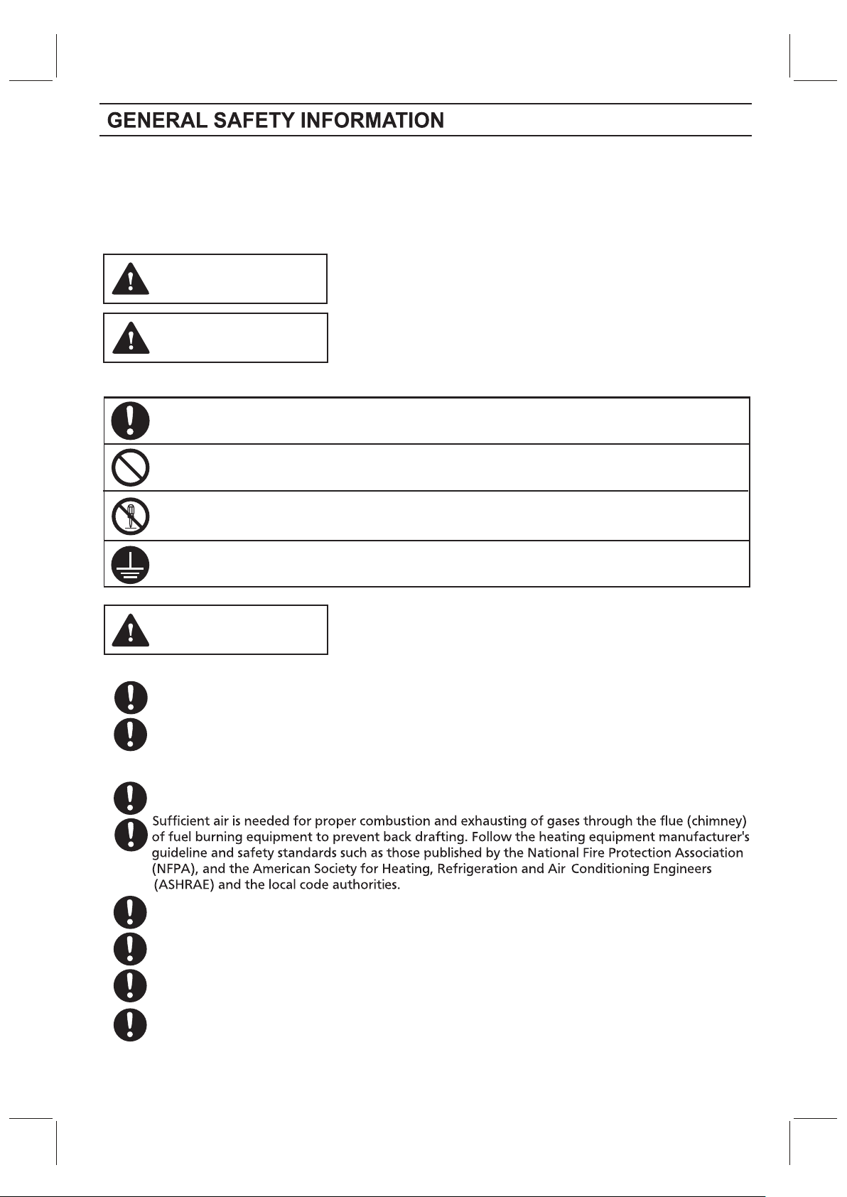
Provide make up air for proper ventilation.
For general ventilating use only. Do not use to exhaust hazardous or
explosive materials and vapors.
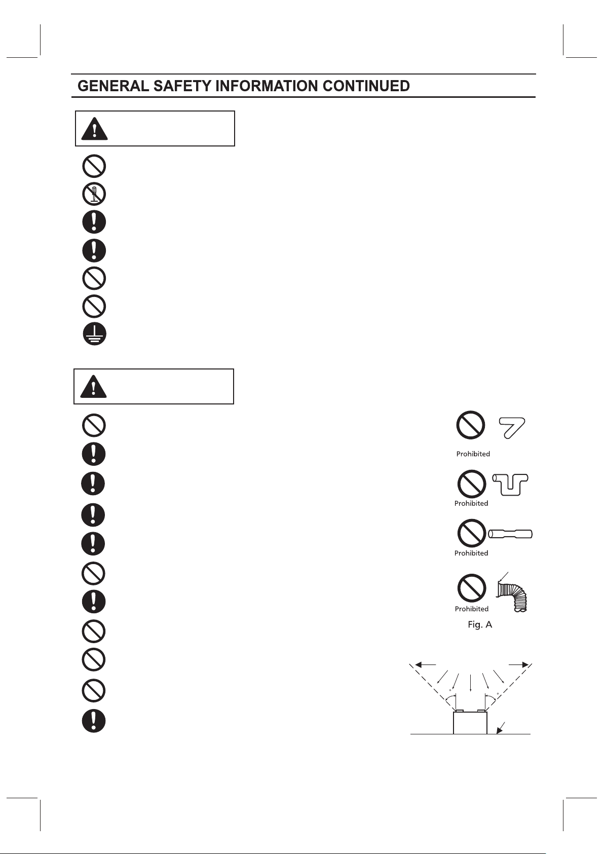
Do not install the unit where ducts are configured as shown
in Fig.A.
Not for use in cooking area. (Fig.B)
The special-purpose or dedicated parts, such as mounting
fixtures, must be used if such parts are provided.
Do not install above or
(Cooking area)
inside this area
45
Cooking
equipment
Fig. B
Adaptor
45
Floor
3
PLEASE READ PRIOR TO INSTALLING THIS FAN
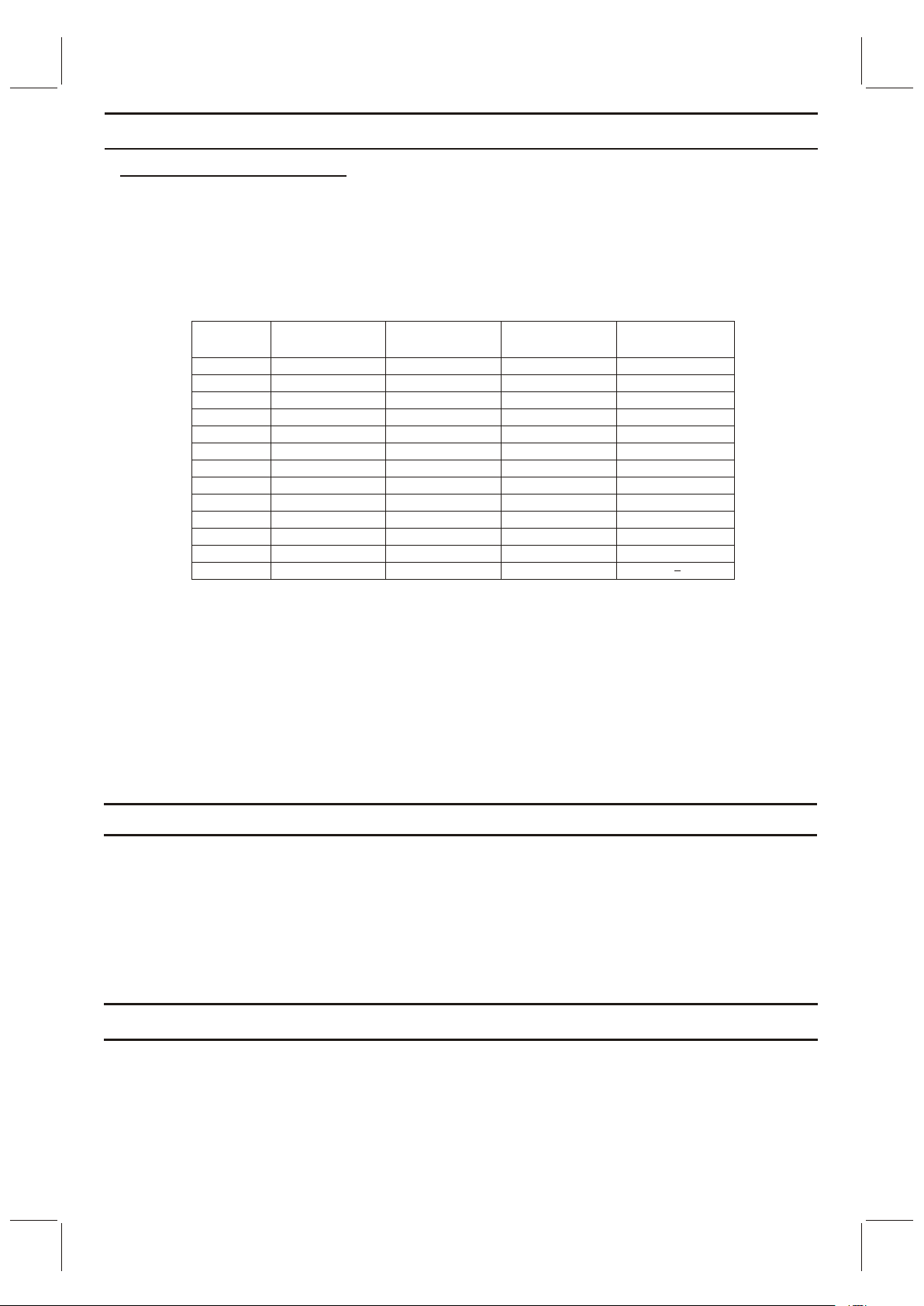
Spot and Continuous Ventilation: These fans are designed to run continuously ensuring a healthy
environment at low CFM levels 24 hours a day. By utilizing the optional CustomVent Multi-Speed
module the fans are built to run continuously at a pre-set lower level (FV-05-11VKS1 and FV-05-11VK1:
0, 30, 40, 50, 60, 70, 80, 90, 100 CFM; FV-11-15VK1: 0, 50, 60, 70, 80, 90, 100, 110, 120 CFM). The
setting is dependent on the size of the house and the individual wishes of the homeowner. It is crucial
that the installer pre-set the lower setting during the installation. Please refer to the chart below
and the switch indication on page 6.
CustomVent Multi-Speed module (Lower Setting). ASHRAE 62.2-2010
(sq.feet)
<1,000
1,500
2,000
2,500
3,000
3,500
4,000
4,500
5,000
5,500
6,000
6,500
7,000
These fans are also built to take care of the homeowner’s spot ventilation needs when the room is
occupied. The basic fan models allow a choice of three speeds. When fans are equipped with the optional
Multi-Speed module, these models kick up to a maximum level of 150 CFM for the FV-11-15VK1 and 110
CFM for the FV-05-11VKS1 and FV-05-11VK1 either when the switch is turned on or activated by the
optional Condensation Sensor module or the optional Motion Sensor module.
A High/Low Delay Timer, located inside the fan unit, is utilized to return the fan back to the pre-set
Continuous ventilation mode. The installer needs to consult with the homeowner for the desired
setting on the timer (0 - 60 minutes) and make the adjustments during the installation.
Two Bedrooms
33
38
43
48
53
58
63
68
73
78
83
88
93
Three Bedrooms
40
45
50
55
60
65
70
75
80
85
90
95
100
Four Bedrooms
48
53
58
63
68
73
78
83
88
93
98
103
108
Five Bedrooms
55
60
65
70
75
80
85
90
95
100
105
110
DESCRIPTION
These products are listed by UL under UL file No. E78414.
These products use a sirocco fan driven by a DC motor powered by an integral transformer. The motor is
designed to have long operating life, high dynamic response, higher speed ranges with saving energy.
The grille covering the fan body is a spring-loaded, quick remove type. A damper for preventing air counter
flow is provided. The blower uses a high-capacity sirocco fan developed to reduce the noise level.
UNPACKING
Unpack and carefully remove the unit from carton.
Refer to the Supplied Accessories list to verify that all parts are present.
44
 Loading...