

Panasonic FV-05, FV-08, FV-11VF2 Service Manual
Service Manual
PEG0510035CE
Version:1401
CONTENTS
1 Parts Identification
2 Wiring Diagram
3 Parts List
PAGE
11
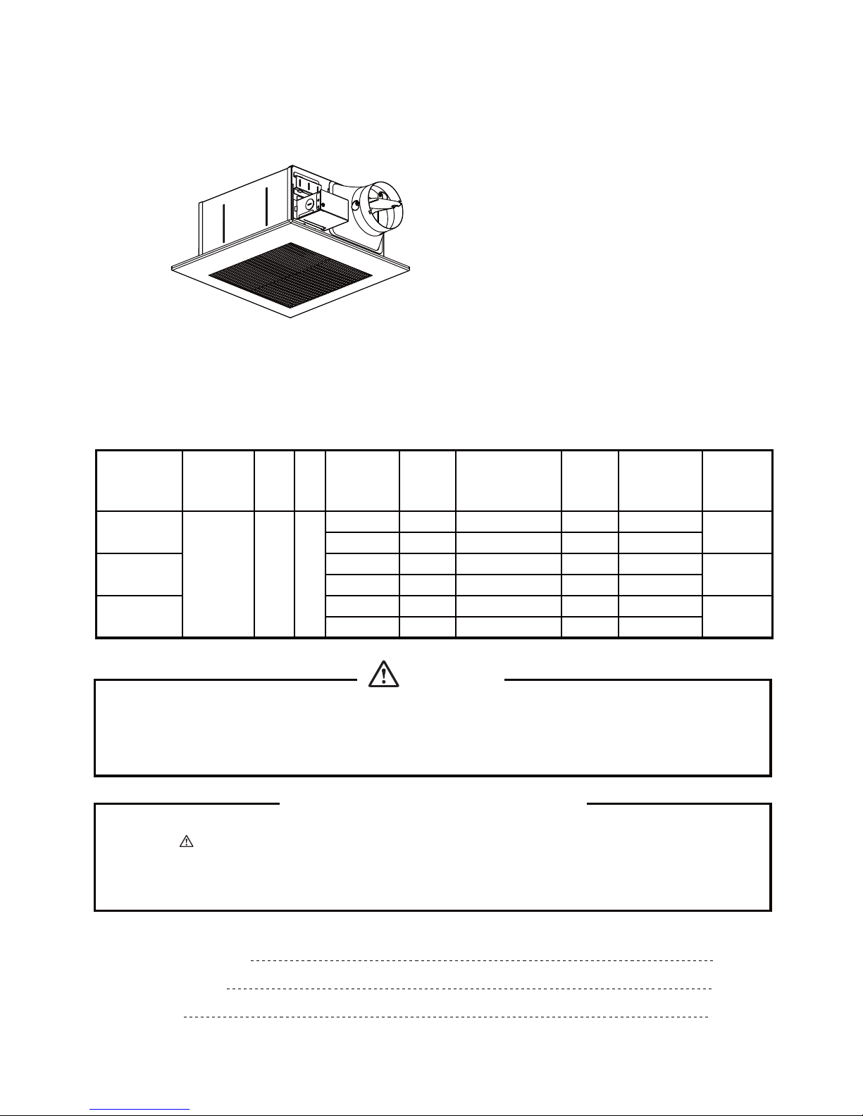
Super Quiet Ventilating Fan
FV-05/08/11VF2
1~10
12~15
SPECIFICATIONS
WhisperFit
(North America Market)
Remark: Because of different structure, we divide this model into Version A & Version B.
In Version A, we also divide into Style A & Style B. The change points are mainly
refer to the installation method and the cord section. please pay attention when
you order these service parts.
TM
Duct
diameter
Noise
Power
consumption
Speed Air deliver Weight
(inches) (sones) (W) (rpm) (cfm) Ib. (kg)
3 0.5 15 740 50
4 0.4 15 635 50
3 0.8 24 845 70
4 0.8 24 755 80
3 1.5 33 1230 90
4 1.5 33 830 110
Sepcifications are based on HVI standard.
Air
direction
Exhaust 120
HzV
FV-05VF2
FV-08VF2
FV-11VF2
Model No.
10.6 (4.8)
11.0 (5.0)
11.2 (5.1)
60
WARNING
This service information is designed for experienced repair technicians only and is not designed for use by
the general public. It does not contain warnings or cautions to advise non-technical individuals of potential
dangers in attempting to service a product. Products powered by electricity should be serviced or repaired
only by experienced professional technicians. Any attempt to service or repair the product or products dealt
with in this service information by anyone else could result in serious injury or death.
IMPORTANT SAFETY NOTICE
There are special components used in this equipment which are important for safety. These parts are
marked by in the Schematic Diagrams, Exploded Views and Replacement Parts List. It is essential
that these critical parts should be replaced with manufacturer's specified parts to prevent shock, fire
or other hazards. Do not modify the original design without permission of manufacture.
We suggest to handle such parts after the static electricity prevention.
It is forbidden to touch the PCB parts by bare hands during the repairing process.
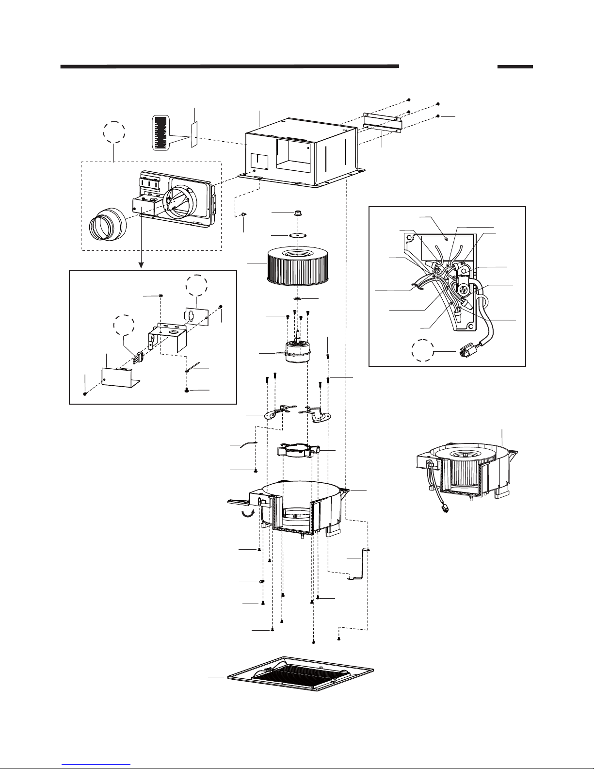
1 Parts Identification
FV-05VF2
1
2
3
5
4
6
7
12
8
10
11
13
14
16
19
(4pcs)
18(4pcs)
31
22
9
17
20
21
(4pcs)
(24)
23
(3pcs)
25
(4pcs)
Details of Junction Box
Motor Lead
(Black)
Motor Lead
(Red)
Motor Lead
(White)
Cord
(White)
Cord
(Black)
Cord
(Green)
Details of Wiring
35
32
36B
33
(5pcs)
1
15B
26
29
(29)
30
(22)
(31)
28B
27B
Remark: Please pay attention to the parts which circled with broken line , you can
for details.
refer
to the following 3 pages
37
mm
Inch
60
2
50
40
30
20
10
1
_
2
2
1
1
_
2
1
1
_
2
(31)
34
24
(2pcs)
Fan Assy.
58
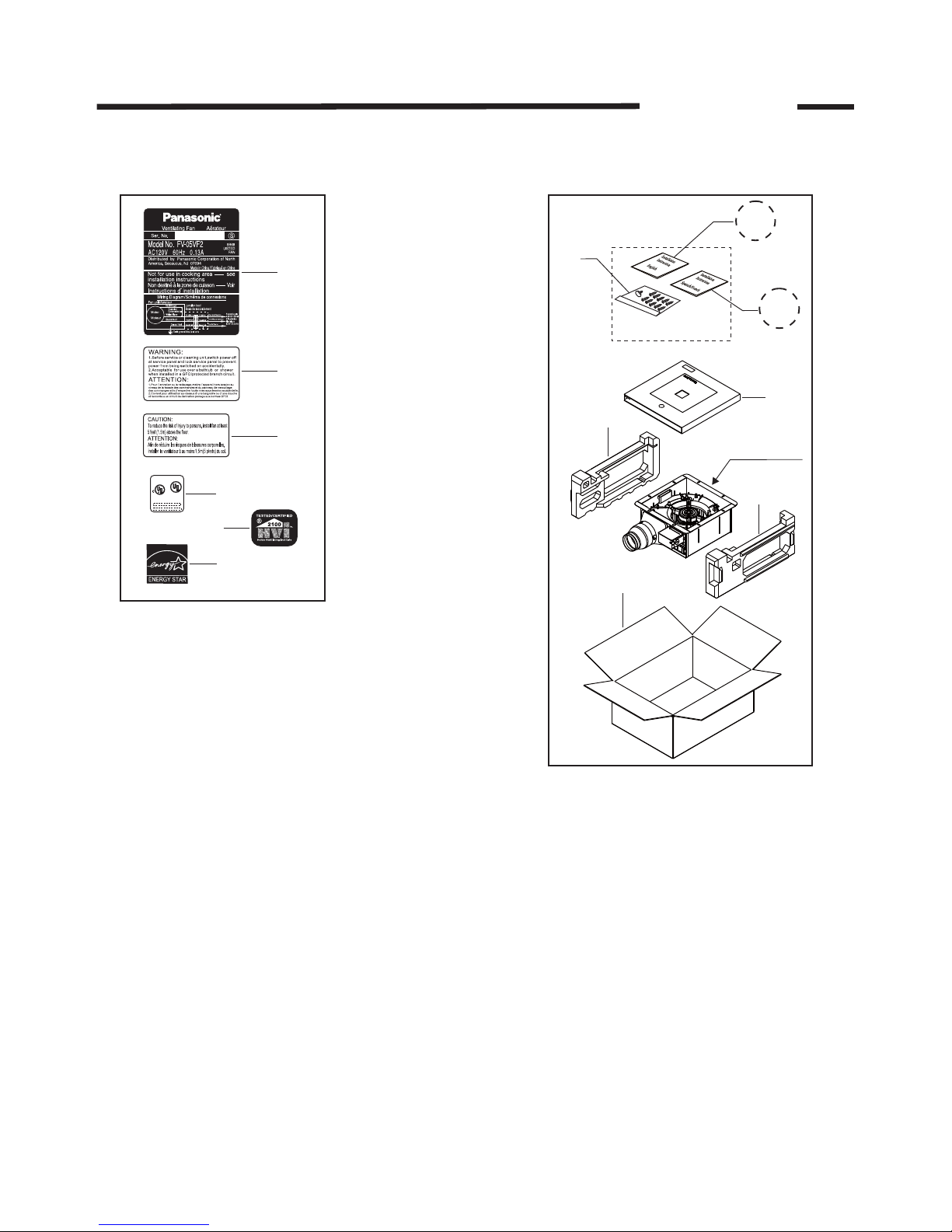
1 Parts Identification
FV-05VF2
2
Main Labels
(For Reference)
38
39
40
43
42
41
FAN
US
LISTED
E78414
Main Packing Materials
47
46
45
44
Fan body
55B
57
56B
1 Parts Identification
FV-05VF2
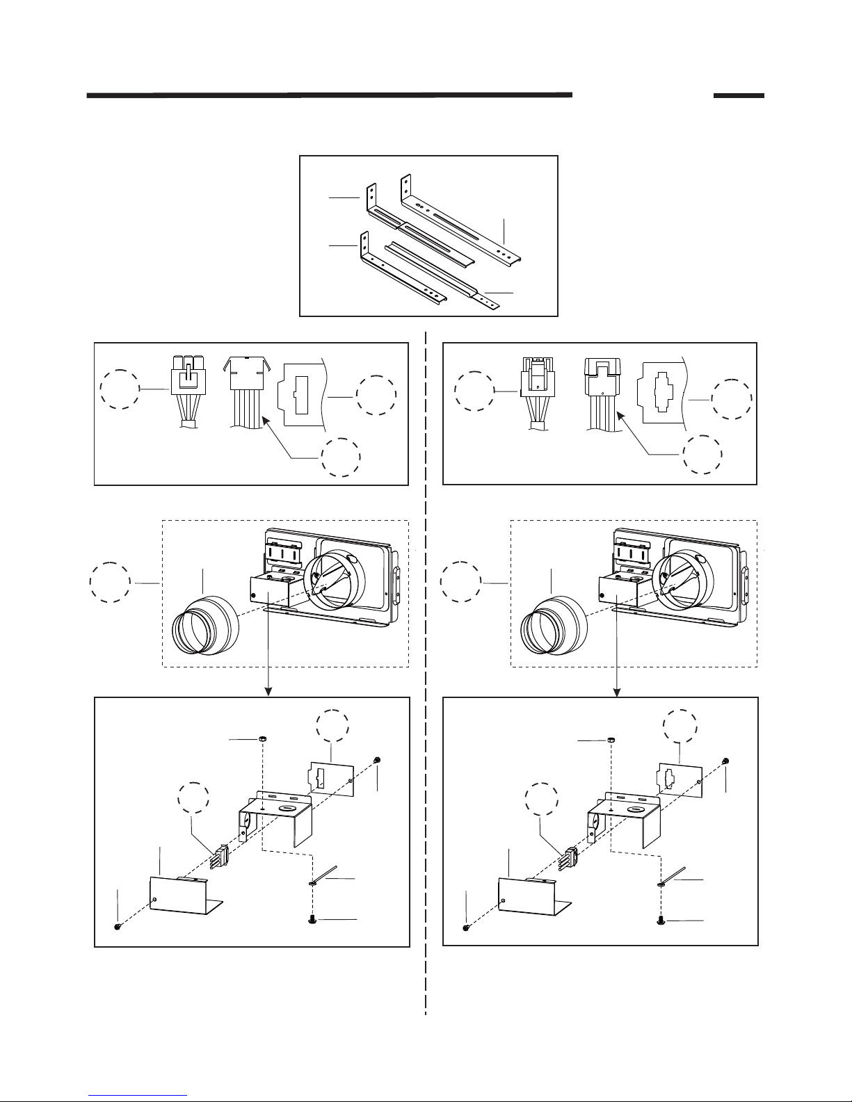
15AA
48
49
51
50
LR-03
LP-03
(36A)
Style A
(28A)
(27A)
VLR-03
VLP-03
(36B)
Style B
(28B)
(27B)
26
29
(29)
30
(22)
(31)
28B
27B
26
29
(29)
30
(22)
(31)
28A
27A
Details of Connector Cord
Details of Connector Cord
Details of Junction Box
Details of Junction Box
16
15AB
16
Parts For Version A
3
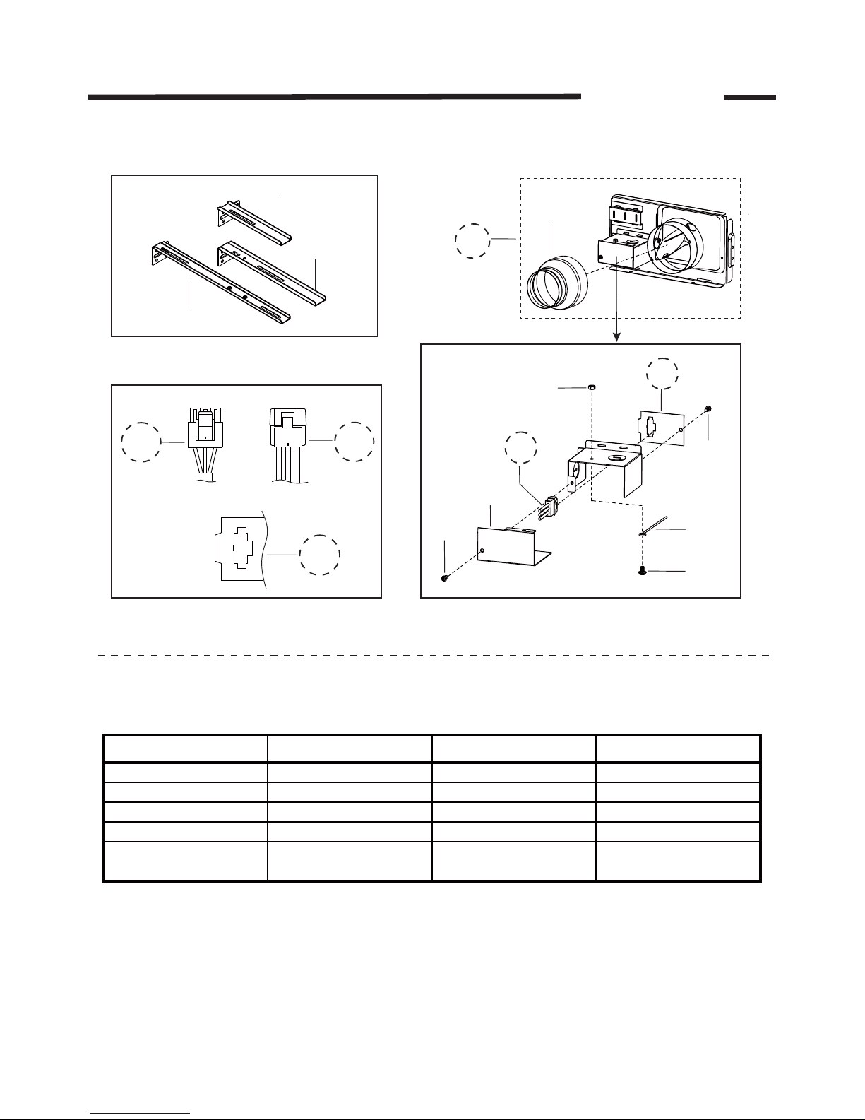
1 Parts Identification
FV-05VF2
Installation Attachment
VLR-03
VLP-03
(36B)
(28B)
(27B)
Details of Connector Cord
26
29
(29)
30
(22)
(31)
28B
27B
15B
Details of Junction Box
16
Parts For Version B
List For Parts Differentiation
4
Remark: For your convenience, we list the differentiation parts above, when you need to
order these parts, please judge which version or style is adapt to your machine
first. Especially, if you need to order theAdapter Assy.,please refer to the
following 1 page for details.
53
54
52
Part name Style A of Version A Style B of Version A Version B
Cord 36A 36B 36B
Adapter Assy. 15AA 15AB 15B
Connector Plate 28A 28B 28B
Connector Assy. 27A 27B 27B
Installation Instruction
(English)
55A 55A 55B
 Loading...