

Panasonic EYFPA1JR Owner's Manual
Operating Instructions
Instructions d’utilisation
Manual de instrucciones
Cordless Impact Wrench
Clé de serrage à impact sans l
Llave de impacto inalámbrica
Model No: EYFPA1J / EYFPA1JR
Before operating this unit, please read these instructions completely and save this manual for future use.
Lire entièrement les instructions suivantes avant de faire fonctionner l’appareil et conserver ce mode d’emploi à des
fins de consultation ultérieure.
Antes de usar este aparato por primera vez, lea todas las instrucciones de este manual y guarde el manual para
poderlo consultar en el futuro.
Index/Index/Indice
EYFA31
A
B
C D
English: Page 6
Français: Page 22
Español: Página 40
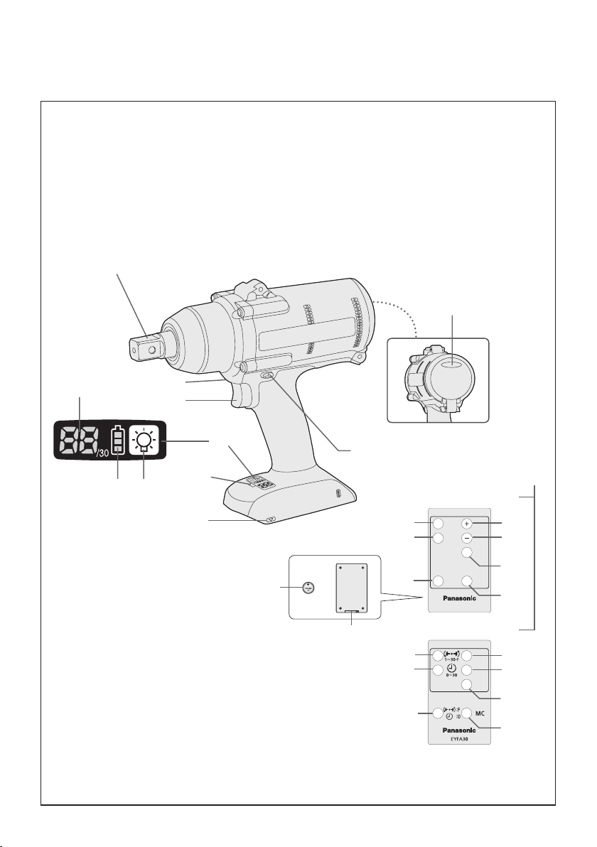
FUNCTIONAL DESCRIPTION
DESCRIPTION DES FONCTIONS
DESCRIPCIÓN FUNCIONAL
(A)
(B)
(I)
(K)
(J)
(F)
(G)(H)
(E)
(D)
(U)
Remote control and battery are not included.
La télécommande et la batterie ne sont pas incluses.
El control remoto y la batería no están incluídos.
-
2 -
(T)
(C)
(S)
(R)
(Q)
(Y)
(X)
(W)
(L)
EYFA31
(M)
(N)
(O)
(P)
EYFA30
(M)
(N)
(O)
(V)

Square drive
Entraînement carré
(A)
Excitador cuadrado
Forward/Reverse lever
Levier d’inversion marche avant/marche arrière
(C)
Palanca de avance/marcha atrás
Remote control receiver
Récepteur de la télécommande
(E)
Receptor de control remoto
LED light on/off button
Bouton Marche/Arrêt de la lumière DEL
(G)
Botón ON/OFF de luz LED
Display
Afchage
(I)
Visor
LED light
Lumière DEL
(K)
Luz indicadora
+ button
Bouton +
(M)
Botón +
OK button
Bouton OK
(O)
Botón OK (correcto)
C button
Bouton C
(Q)
Botón C
A button
Bouton A
(S)
Botón A
Battery
Batterie
(U)
Batería
Format button
Bouton de format
(W)
Botón de formato
Torque set button
Bouton de réglage du couple de serrage
(Y)
Botón de ajuste de par de torsión
Tightening conrmation lamp
Témoin de conrmation de serrage
(B)
Lámpara de conrmación de apriete
Alignment mark
Marques d’alignement
(D)
Marcas de alineación
Control panel
Panneau de commande
(F)
Panel de control
Battery indication lamp
Témoin indicateur de la batterie
(H)
Lámpara de indicadora de la batería
Variable speed control trigger
Gâchette de commande de vitesse
(J)
Disparador del control de velocidad variable
Remote control
Télécommande
(L)
Control remoto
− button
Bouton −
(N)
Botón −
D button
Bouton D
(P)
Botón D
B button
Bouton B
(R)
Botón B
Holder
Support
(T)
Retenedor
Torque level button
Bouton de niveau du couple de serrage
(V)
Botón de palanca de par de torsión
Interval set button
Bouton de réglage de l’intervalle
(X)
Botón de ajuste de intervalo
-
3 -
Illustrations/Illustrations/Imágenes
1
rubber ring
anneau en caoutchouc
anillo de caucho
2
3
pin
goupille
pasador
5
groove
rainure
ranura
6
7
4
8
-
4 -
9
10
11
12
13
Forward
Rotation en
sens normal
Avance
Switch lock
Verrouillage de
commutateur
Bloqueo del interruptor
Reverse
Rotation en
sens inverse
Marcha atrás
-
5 -
14

EN EN
I
.
GENERAL SAFETY
RULES
WARNING! Read all instructions
Failure to follow all instructions listed
below may result in electric shock, fire
and/or serious injury. The term “power
tool” in all of the warnings listed below
refers to your mains operated (corded)
powe r tool and battery opera ted
(cordless) power tool.
SAVE THESE INSTRUCTIONS
Work Area Safety
1) Keep work area clean and well lit.
Cluttered or dark areas invite accidents.
2)
Do not operate power tools in explosive
atmospheres, such as in the presence
of flammable liquids, gases or dust.
Power tools create sparks which may
ignite the dust or fumes.
3)
Keep children and bystanders away
while operating a power tool.
Distractions can cause you to lose control.
Electrical Safety
1) Power tool plugs must match the
outlet. Never modify the plug in any
way. Do not use any adapter plugs
with earthed (grounded) power tools.
Unmodified plugs and matching outlets
will reduce risk of electric shock.
2)
Avoid body contact with earthed or
grounded surfaces such as pipes,
radiators, ranges and refrigerators.
There is an increased risk of electric shock
if your body is earthed or grounded.
3) Do not expose power tools to rain or
wet conditions.
Water entering a power tool will increase
the risk of electric shock.
4)
Do not abuse the cord. Never use
the cord for carrying, pulling or
unplugging the power tool. Keep
cord away from heat, oil, sharp edges
or moving parts.
Damaged or entangled cords increase
the risk of electric shock.
5)
When operating a power tool outdoors,
use an extension cord suitable for
outdoor use.
Use of a cord suitable for outdoor use
reduces the risk of electric shock.
Personal Safety
1)
Stay alert, watch what you are doing
and use common sense when operating
a power tool. Do not use a power tool
while you are tired or under the influence
of drugs, alcohol or medication.
A moment of inattention while operating
power tools may result in personal injury.
2)
Use safety equipment. Always wear
eye protection.
Safety equipment such as dust mask,
non-skid safety shoes, hard hat, or
hearing protection used for appropriate
conditions will reduce personal injuries.
3)
Avoid accidental starting. Ensure the
switch is in the off position before
plugging in.
Carrying power tools with your finger on
the switch or plugging in the power tools
that have the switch on invites accidents.
4)
Remove any adjusting key or wrench
before turning the power tool on.
A wrench or a key left attached to a
rotating part of the power tool may result
in personal injury.
5)
Do not over reach. Keep prope r
footing and balance at all times.
This enables better control of the power
tool in unexpected situations.
6)
Dress properly. Do not wear loose
clothing or jewellery. Keep your
hair, clothing and gloves away from
moving parts.
Loose clothes, jewellery or long hair can
be caught in moving parts.
7)
If devices are provided for t he
connection of dust extraction and
collection facilities, ensure these are
connected and properly used.
Use of these devices can reduce dust
related hazards.
Power Tool Use and Care
1)
Do not force the power tool. Use the
correct power tool for your application.
The correct power tool will do the job
better and safer at the rate for which it
was designed.
2)
Do not use the power tool if the
switch does not turn it on and off.
Any power tool that cannot be controlled
with the switch is dangerous and must
be repaired.
3)
Disconnect the plug from the power
source and/or the battery pack from
-
6 -

the power tool before making any
adjustments, changing accessories,
or storing power tools.
Such preventive safety measures
reduce the risk of starting the power tool
accidentally.
4)
Store idle power tools out of the reach
of children and do not allow persons
unfamiliar with the power tool or these
instructions to operate the power tool.
Power tools are dangerous in the hands
of untrained users.
5)
Maintain power tools. Check for
misalignment or binding of moving
parts, breakage of parts and any other
condition that may affect the power
tools operation. If damaged, have the
power tool repaired before use.
Many accidents are caused by poorly
maintained power tools.
6)
Keep cutting tools sharp and clean.
Properly maintained cutting tools with
sharp cutting edges are less likely to
bind and are easier to control.
7)
Use the power tool, accessories
and tool bits etc. in accordance with
these instructions and in the manner
intended for the particular type of
power tool, taking into account the
working conditions and the work to
be performed.
Use of the power tool for operations
different from those intended could
result in a hazardous situation.
Battery Tool Use and Care
1) Ensure the switch is in the off position
before inserting battery pack.
Inserting battery pack into power tools
that have the switch on invites accidents.
2)
Recharge o nly with the charger
specified by the manufacturer.
A charger that is suitable for one type
of battery pack may create a risk of fire
when used with another battery pack.
3)
Use power tools only with specifically
designated battery packs.
Use of any other battery packs may
create a risk of injury and fire.
4)
When battery pack is not in use, keep it
away from other metal objects like paper
clips, coins, keys, nails, screws, or other
small metal objects that can make a
connection from one terminal to another.
Shorting the battery terminals together
may cause burns, or a fire.
5)
Under abusive conditions, liquid may
be ejected from battery; avoid contact.
If contact accidentally occurs, flush
with water. If liquid contacts eyes,
additionally seek medical help.
Liquid ejected from the battery may
cause irritation or burns.
Service
1) Have your power tool serviced by a
qualified repair person using only
identical replacement parts.
This will ensure that the safety of power
tool is maintained.
II
. INTENDED USE
This tool is a Cordless Impact Wrench and can
be used to tighten bolts, nuts, and screws. Additionally, it provides a torque control function
that automatically stops tool operation when
a preset load is reached to deliver consistent
tightening torque. Additionally, a separately
available Assembly Qualier can provide wireless monitoring to determine whether tightening
has been completed properly.
Read the “Safety Instructions” booklet
and the following before using.
III
.
ADDITIONAL SAFETY
RULES
1
) Wear ear protectors when using the
tool for extended periods.
2) Be aware that this tool is always in an
operating condition, since it does not have
to be plugged into an electrical outlet.
3) Hold power tools by insulated gripping
surfaces when performing an operation
where the cutting tool may contact hidden wiring or its own cord.
Contact with a “live” wire will make eposed
metal parts of the tool “live” and shock the
operator.
4) Do NOT operate the Forward/Reverse
lever when the main switch is on. The battery will discharge rapidly and damage to
the unit may occur.
5) During charging, the charger may become
slightly warm. This is normal.
Do NOT charge the battery for a long period.
6) When storing or carrying the tool, set the
Forward/Reverse lever to the center position (switch lock).
-
7 -
7) Do not strain the tool by holding the speed
EN EN
control trigger halfway (speed control
mode) so that the motor stops.
NOTE:
• Be sure to attach the rubber ring to pre
vent the pin from falling out.
-
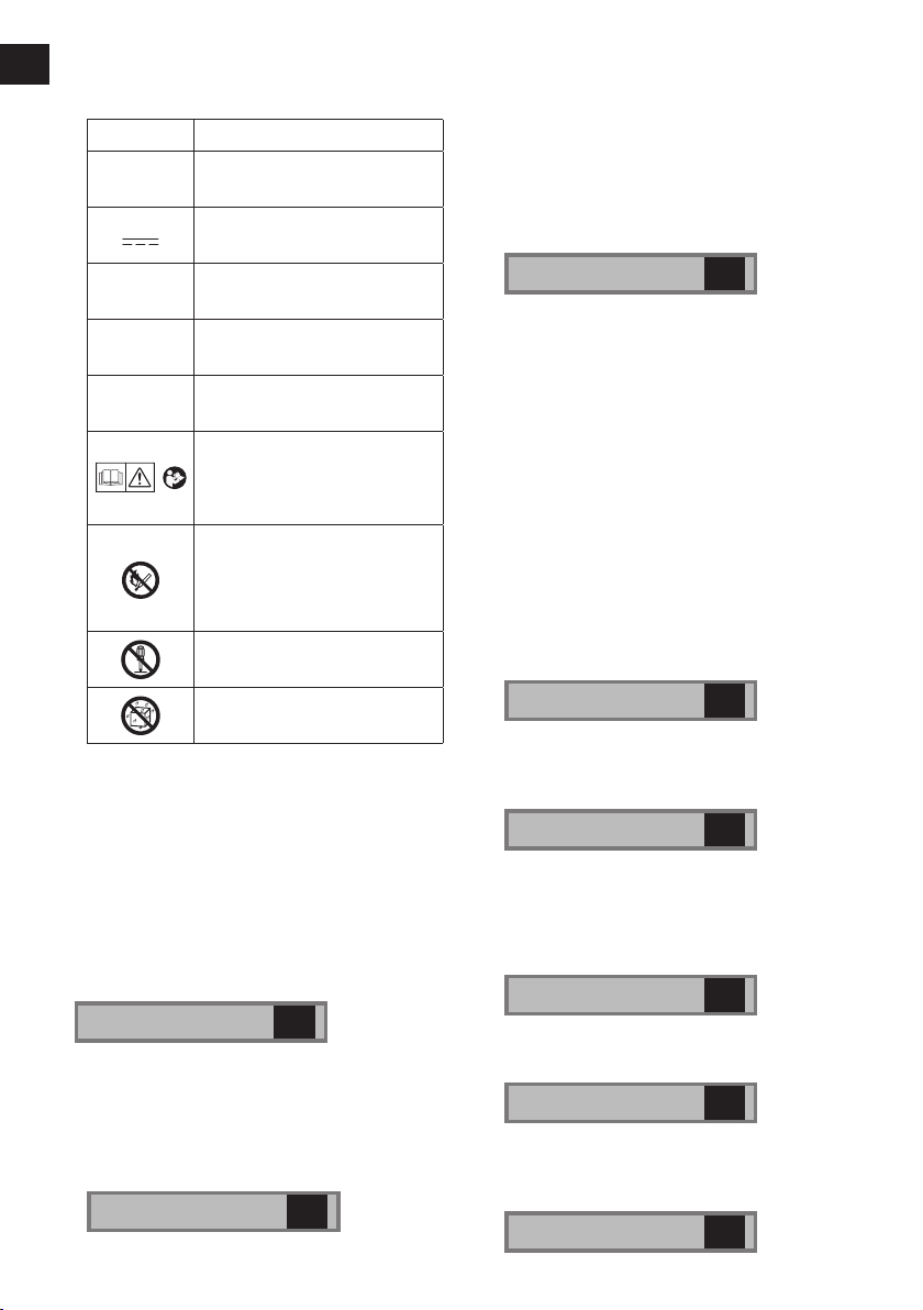
Symbol Meaning
V
n
0
-1
… min
Ah
IV
. ASSEMBLY
NOTE:
• If a worn or deformed socket is used,
the square drive (retainer ring and pin)
may not enter the socket properly.
reciprocations per minutes
Electrical capacity of battery
injury, user must read and
understand instruction
Do not incinerate or heat
battery pack. Do not charge
or use under conditions of
high temperature. Do not ex-
pose to high temperatures.
Do not disassemble or
Do not expose to rain or
Volts
Direct current
No load speed
Revolutions or
pack
To reduce the risk of
manual.
modify.
water.
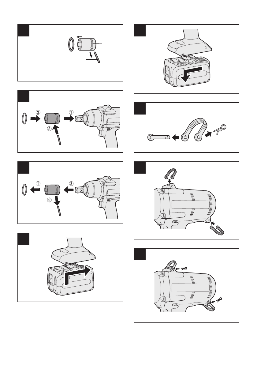
Attaching Socket (Pin type)
• Remove the socket’s rubber ring and pin.
See the illustration
1 Attach the socket to the tool.
2 Insert the pin. (Taking care to align the pin
holes on the socket and tool.)
3 Attach the rubber ring by sliding it into
place over the groove.
See the illustration
1
2
Removing Socket (Pin type)
1 Remove the rubber ring.
2 Remove the pin.
3 Remove the socket from the tool.
See the illustration
NOTE:
• Keep the temperature of the tool above
the freezing point (0°C/32°F) when
attaching sockets to or removing them
from the square drive on the tool. Do
not use excessive force when attaching
or removing sockets.
3
Attaching or Removing Battery Pack
1. To connect the battery pack:
Line up the alignment marks and attach
the battery pack.
• Slide the battery pack until it locks into
position.
See the illustration
2. To remove the battery pack:
Push up on the button from the front to release the battery pack.
See the illustration
4
5
Attaching the tool hanger
1. Remove the pin and the clip from the tool
hanger
See the illustration
2. Align the holes on the tool hanger with the
holes on the tool body.
See the illustration
3. Insert the pin into the holes on the tool
hanger and the tool body.
Attach the clip on the tool hanger's holes.
See the illustration
6
7
8
-
8 -
V.
Vertically
A
p
p
r
o
x
.
6
0
°
A
p
p
r
o
x
.
6
0
°
Approx. 50 cm
OPERATION
Comparison chart for EYFA31 / EYFA30
remote control
EYFA31 EYFA30
D button (P) Torque level button (V)
C button (Q) Format button (W)
B button (R) Interval set button (X)
A button (S) Torque set button (Y)
This operating instruction is written with
the contents of EYFA31 model.
In the case of use with EYFA30, refer to
the above chart and replace EYFA30 with
EYFA31.
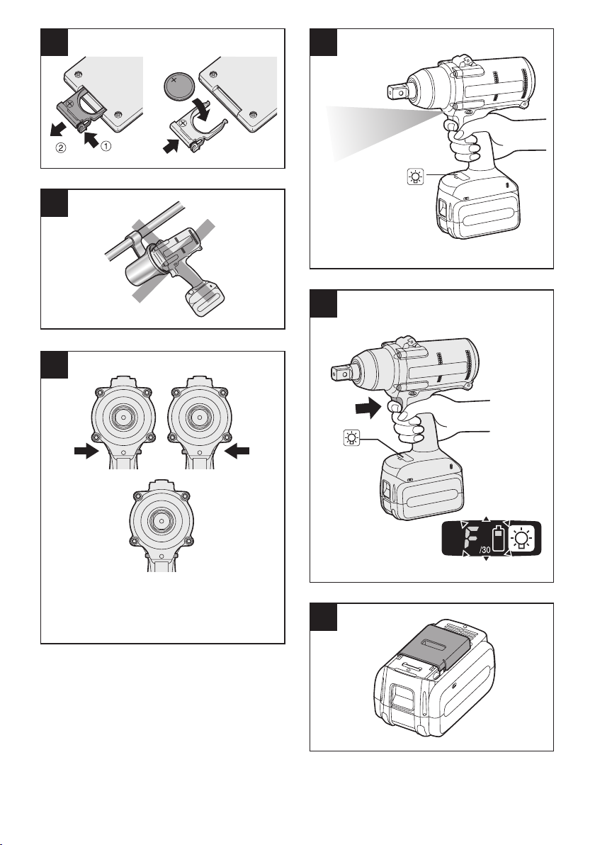
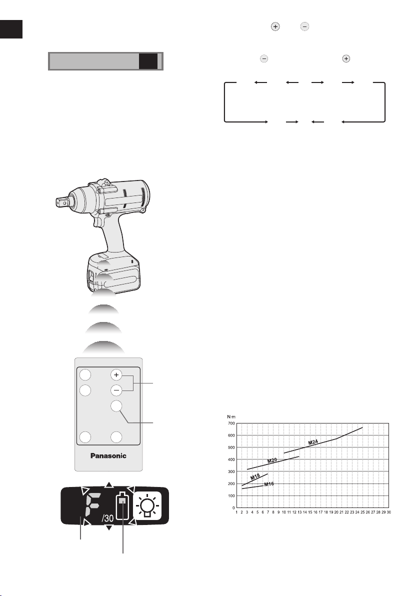
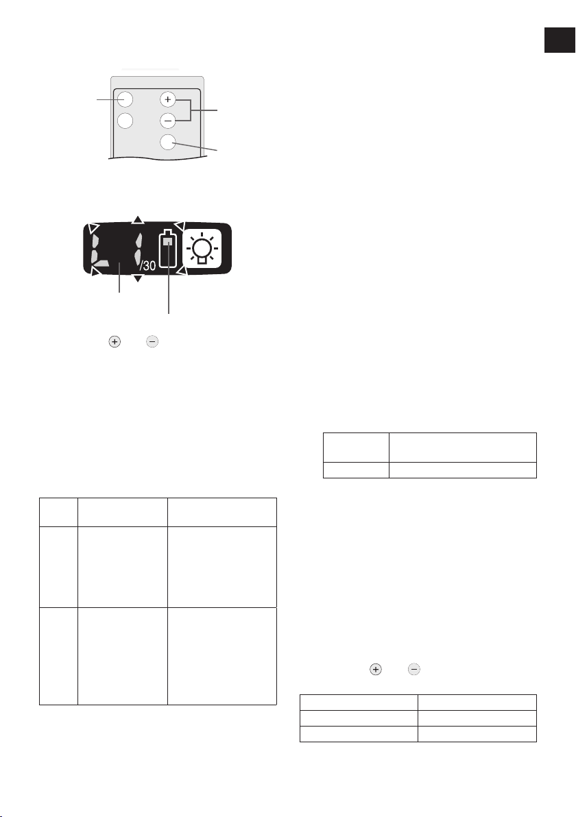
Before Using the Remote
Control (Available as an
optional accessory)
See the illustration
Insert the battery
1. Pull out the battery holder.
1 Push in on the fastener as indicated by the
arrow.
2 Pull out the holder.
2. Insert the battery and push the holder
back in.
NOTE:
• If the tool does not respond to the wire
less remote control even when the
remote control is operated close to
the tool, the battery (CR2025) is dead.
Replace it with a fresh battery.
The included battery is provided for sam-
•
ple use and may not last as long as commercially available batteries
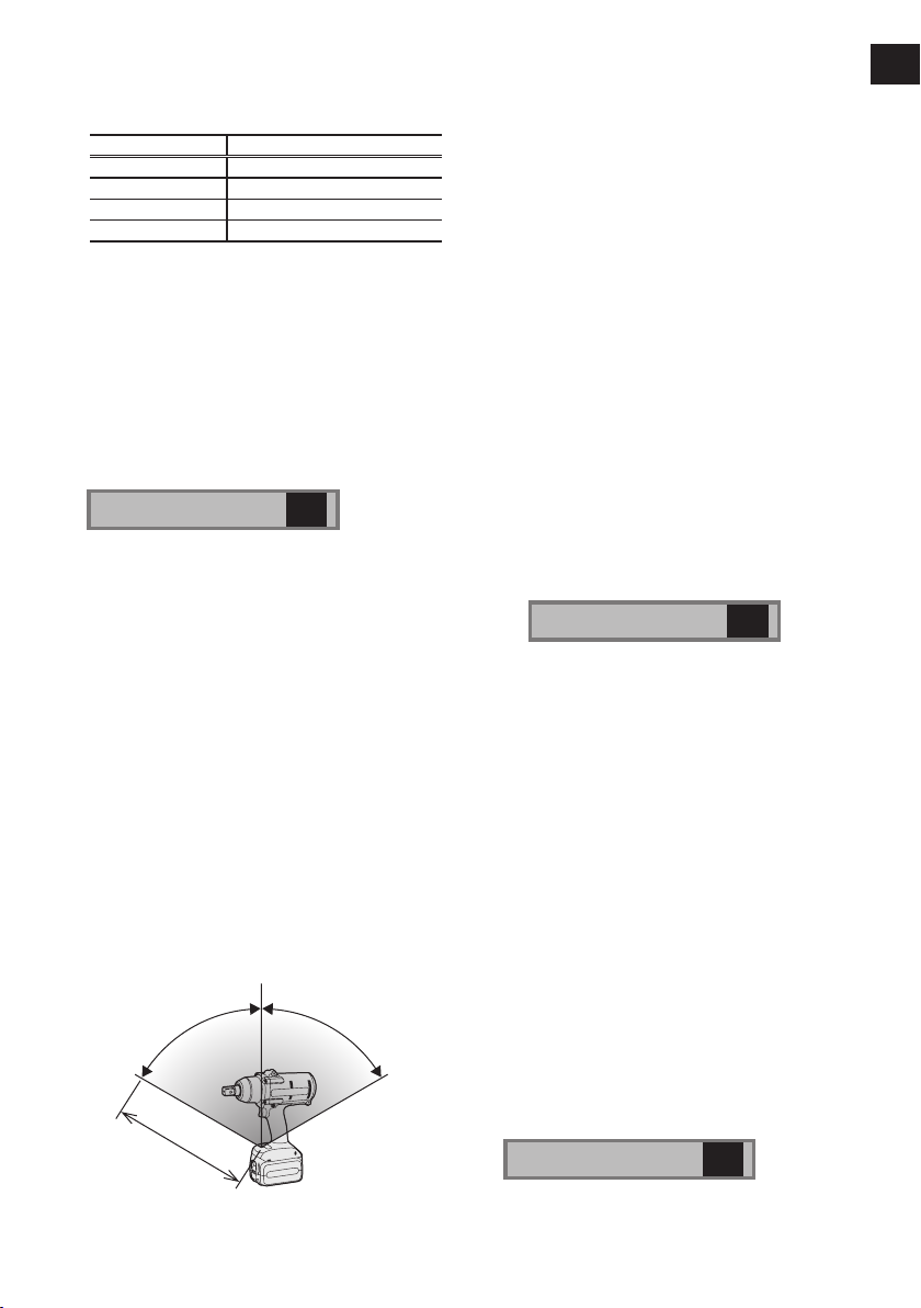
Wireless remote control range
9
.
The remote control should be operated within
approximately 50 cm and approximately 60
vertically and horizontally of the perpendicular
relative to the infrared receiver on the tool.
• Under the following circumstances, you may
not be able to operate the tool, even within
this range.
• If there is an object between the remote
control’s transmitter and the tool’s receiver.
• Use outdoors or in other environments
where the remote control receiver is
exposed to a strong light source, or when
the remote control transmitter or receiver is
dirty may cause the tool to fail to respond,
even when the remote control is used within
the operating range.
[Main Body]
CAUTION:
If a t ool h older i s u sed with the
•
Panasonic EYF series assembly tools,
make sure the tool’s trigger switch
doesn’t hit the tool holder. It may run the
tool accidentally and result in battery
failure by unexpected battery discharge.
See the illustration
CAUTION:
• When operating the tool by depressing
the trigger, there may be a momentary
lag before rotation starts. This does not
-
signal a malfunction.
This lag occurs as the tool’s circuitry
*
starts up when the trigger is depressed
for the first time after installing a new
battery pack or after the tool has not
been used for at least 1 minute (or at
least 5 minutes when the LED is on).
Rotation will start without any lag during second and subsequent operations.
NOTE:
• Quick ON/OFF operation results in a
slightly longer lag before the rotation
starts.
10
°
Switch and Forward/Reverse
Lever Operation
See the illustration
-
9 -
11
EN EN
CAUTION:
To prevent damage, do not operate
•
Forward/Reverse lever until the bit
comes to a complete stop.
Forward Rotation Switch
Operation
1. Push the lever for forward rotation.
2. Depress the trigger switch slightly to start
the tool slowly.
3. The speed increases with the amount of
depression of the trigger for efficient tightening of screws. The brake operates and
the bit stops immediately when the trigger
is released.
4. After use, set the lever to its center posi
tion (switch lock).
-
CAUTION:
• When the tool stops automatically after
the switch is released during impactmode tightening and then reengaged
within 1 second, the red lamp will light up
to indicate the risk of excessive torque
application as a result of retightening.
NOTE:
• The tightening confirmation lamp will not
turn on under the following conditions:
• When the torque clutch is set to “F”
• During reverse rotation operation
• The lamp turns off when the tool is in
operation.
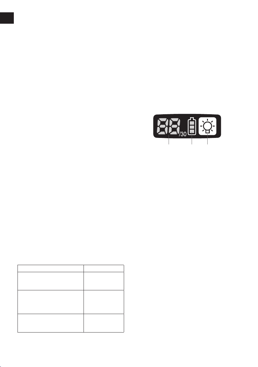
Control Panel
Reverse Rotation Switch
Operation
1. Push the lever for reverse rotation. Check
the direction of rotation before use.
2. Depress the trigger switch slightly to start
the tool slowly.
3. After use, set the lever to its center posi
tion (switch lock).
CAUTION:
• To eliminate excessive temperature
increase of the tool surface, do not
operate the tool continuously using two
or more battery packs. Tool needs cool
off time before switching to another
pack.
Tightening confirmation lamp
• The tightening confirmation lamp can be
used to check whether the torque control
function was activated.
Tool status Lamp display
Tightening complete
(with torque control
function operation)
• Tightening not complete
• Tightening complete
with retightening within 1
second
The automatic stop
function has been
activated.
Green
(For approx. 2
seconds)
Red
(For approx. 2
seconds)
Red
(For approx. 5
minutes)
(1) The torque control function
• The torque control function calculates the
load from the motor’s rotational angle during
the hammer impact and determines that the
bolt has been properly seated when a pre-
set load value is exceeded. Driving is then
automatically stopped after a preset number
of impacts have been delivered to the bolt.
CAUTION:
•
• Always operate the tool with the switch
• In work where a heavy load comes to
• Repeated tightening of the same bolt
(1) (2) (3)
Always check the tool’s tightening torque
before use. The required adjustment
is dependent on the type of threaded
connection and can be best determined
by practical trials. Check the trial screwings with a torque wrench. Improper tool
operation may result in excessive or
inadequate tightening.
fully depressed. The torque control
function will not operate when the
switch is not sufficiently depressed, preventing the tool from stopping automatically.
bear during tightening, the load may be
interpreted as the seating of the bolt,
preventing the bolt from being completely tightened.
may break the bolt or deform the material into which the bolt is being driven as
a result of excessive tightening.
-
10 -
• The tightening torque value and precision vary with factors such as the material into which the bolt is being driven
and the condition of the socket being
used. Adjust the torque as necessary
for the work being performed. Bolt tightening torque varies due to the factors
described below.
1) Bolt
• Bolt diameter: Tightening torque
gener-ally increases with bolt diameter.
• Torque coefficient (indicated by the
bolt manufacturer), grade, length,
etc.
2) Other
• Bit and socket condition: Material,
amount of play, etc.
• Use of a universal joint or socket
adapter
• User: Manner in which the tool
is applied to the bolt, strength
with which the tool is held, manner in which the tool’s switch is
depressed
• Condition of object being tightened:
Ma-terial, seating surface finish
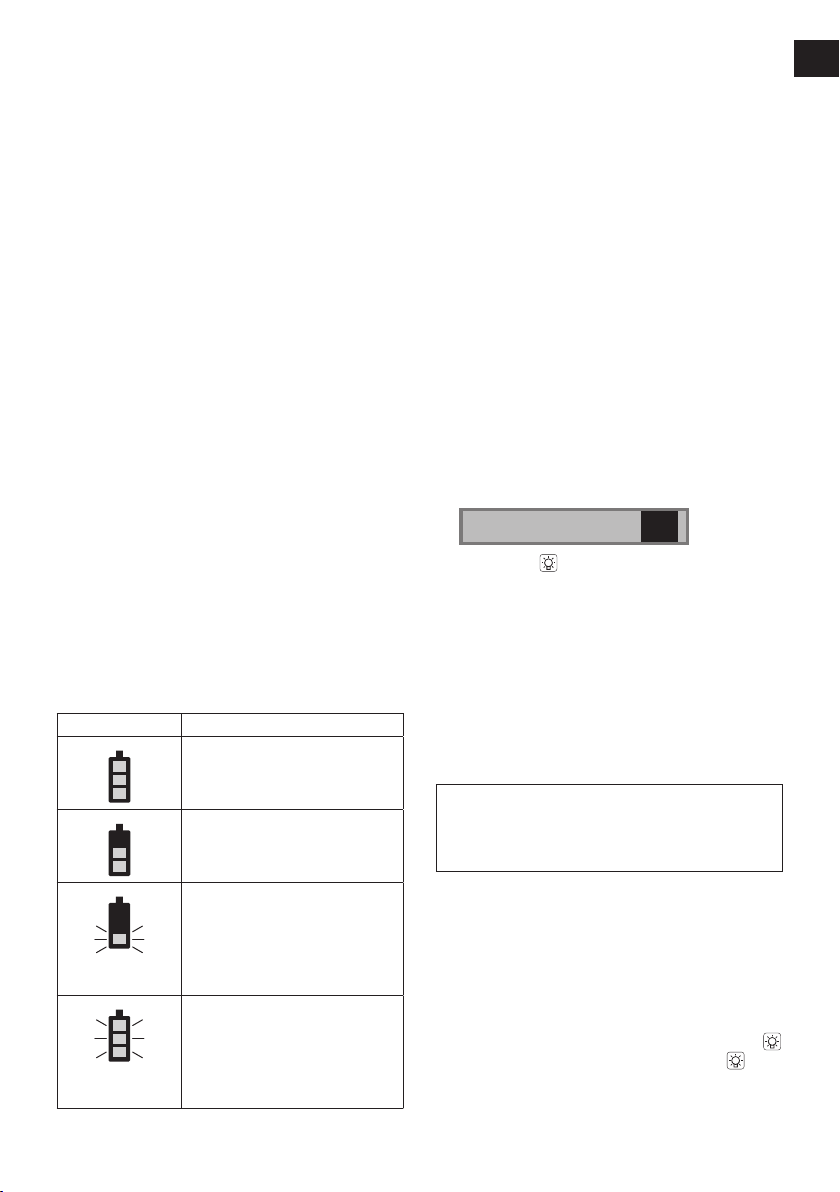
(2) The battery indication lamp
• Use the battery indication lamp to check
how much power is left in the battery.
• Battery life varies slightly with ambient temperature and battery characteristics. The
lamp is designed to provide a rough indication of remaining battery life.
Indicator Battery status
Fully charged
Approx. 40% or less
remaining
Flashing
Approx. 20% or less
remaining (indicates need
to recharge battery)
Flashing
Flashing
The battery pack will need
to be charged soon.
No charge
The battery pack needs to
be charged.
(The tool’s automatic
power-off function will
activate at this stage.)
Automatic power-off function
• The auto matic pow e r-off f unctio n i s
designed to prevent a loss of tightening
torque due to reduced battery voltage. Once
it has been activated, the tool will not operate until the battery pack has been charged
(or re-placed with a fresh unit), even if the
trigger is depressed.
NOTE:
• All 3 bars on the battery indication lamp
will flash when the automatic power-off
function is activated.
• When the battery indication lamp begins
flashing, the battery pack should be
charged (or replaced with a fresh unit)
immediately.
• Be sure to fully charge the battery pack
in question after activation of the automatic power-off function. Failure to do
so may prevent the automatic power-off
function from being properly deactivated.
(3) LED light
See the illustration
Pressing the button toggles the LED light
on and off.
The light illuminates with very low current, and
it does not adversely affect the performance of
the tool during use or its battery capacity.
CAUTION:
The built-in LED light is designed to illu-
•
minate the small work area temporarily.
Do not use it as a substitute for a regu-
•
lar
flashlight, since it does not have
enough brightness
Caution : DO NOT STARE INTO BEAM.
Use of controls or adjustments or performance
of procedures other than those specied herein
may result in hazardous radiation exposure.
12
.
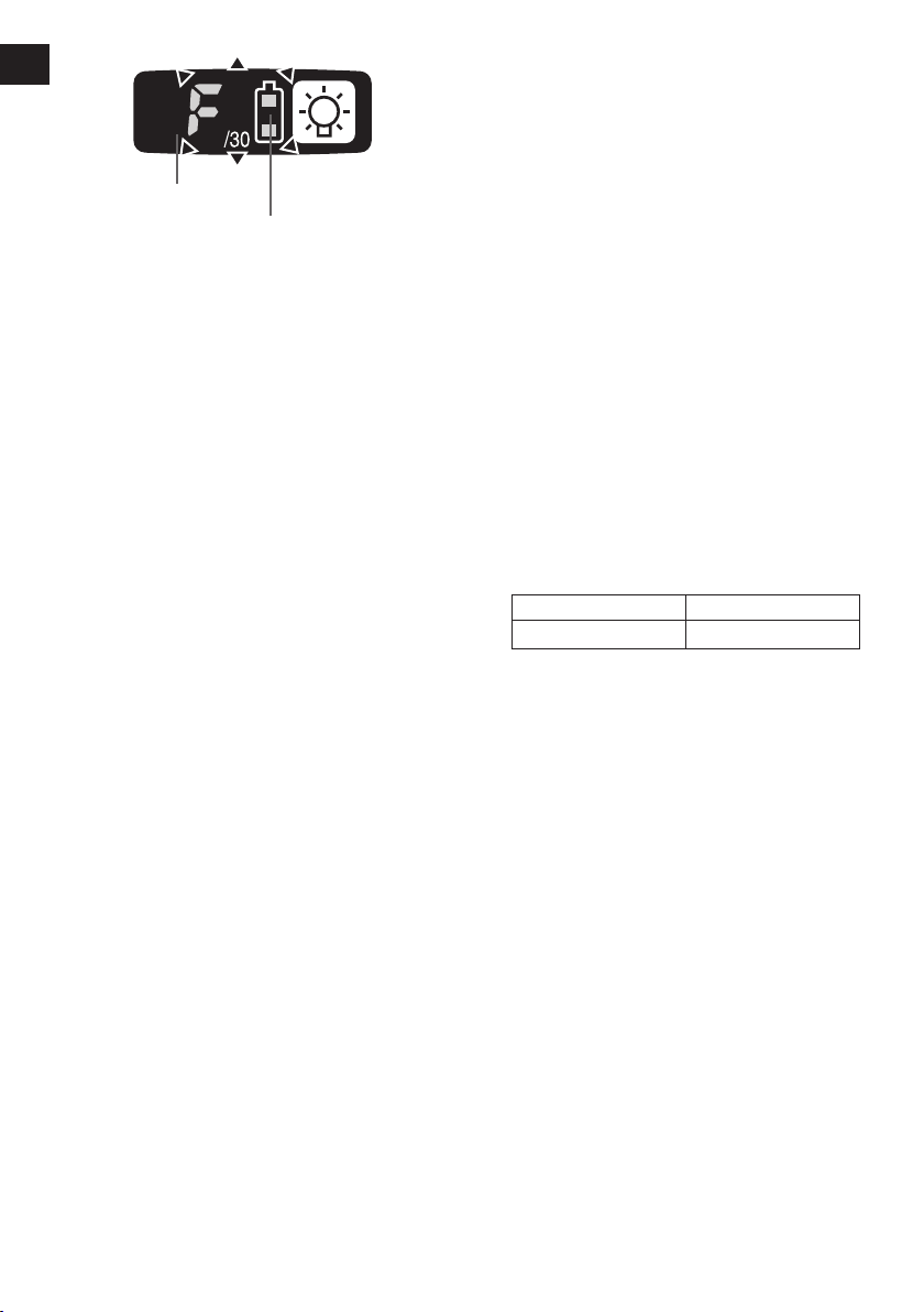
Setting the tool to configuration mode
1. Turn off the control panel.
• If the control panel is on, remove and
then reinsert the battery pack.
2. Depress the switch while pushing the
button and then release both the button and the switch.
-
11 -
EN EN
EYFA31
A
B
C D
3…28
1F30 229
• After all the LED lamps have turned off,
the control panel will flash and change
to configuration mode.
See the illustration
NOTE:
• Tools ship from the factory set to “F”
mode (torque control function off).
• The control panel will turn off if the tool
is not operated for a period of 5 min
utes.
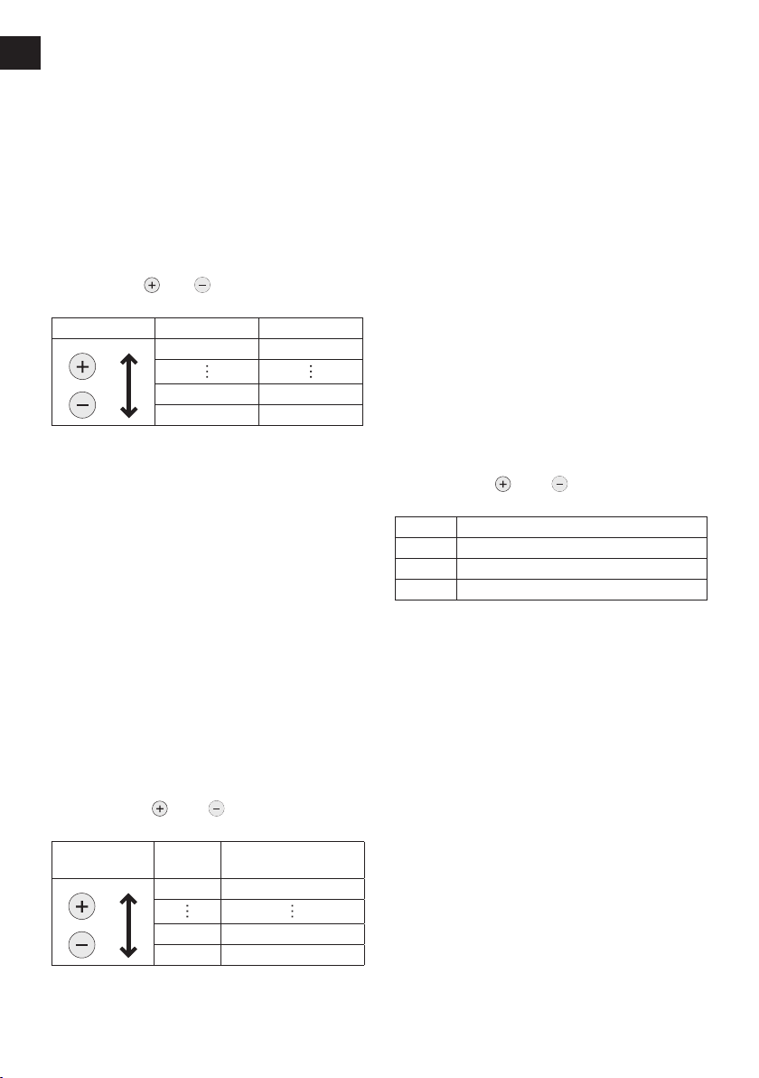
13
Configuring the torque clutch
setting
1. Press the and buttons to select the
clutch setting that is appropriate for the
work being performed.
As the button
is pressed
-
• “F” indicates that the torque control function is off.
• You can select from 30 torque clutch
settings (1 to 30).
• Use figures from the Tightening Torque
Chart to guide your selection of torque
clutch setting. (See the following tightening torque chart)
2. Press the OK button to accept the select
ed torque clutch setting.
• The control panel will stop flashing and
light up.
CAUTION:
• You must press the OK button in order
for the selected setting to take effect.
• Be sure to verify the new value after
changing the setting.
As the button
is pressed
-
Display
Battery indication lamp
(1)
(2)
Tightening Torque Chart (for
reference use)
The values illustrated on this chart were measured under the conditions described below
and are provided for reference purposes.
Actual tightening torque varies with ambient
conditions (the particular bolt being tightened,
hardware being used, method of holding the
bolt in place, etc.).
EYFPA1J, EYFPA1JR
Tightening torque
Torque setting level
-
12 -
Setting the snug point detec-
A
B
tion level
(1)
1. Press the A button.
• The snug point detection level setting
value will be displayed.
Display
Battery indication lamp
2. Press the and buttons to set the best
snug point detection level for the work
you’re performing.
3. Press the OK button to accept the number
of torque stages and the snug point detection level.
• The tool’s panel will flash and then light
up continuously.
Snug point detection level guidelines
Display
L1
L2
Snug point
detection level
Low
(Use for work
characterized by
low loads before
the snug point is
reached.)
High
(Use for work
characterized
by high loads
before the
snug point is
reached.)
CAUTION:
• Set the snug point detection level from
“L1.” Setting the snug point detection level
from “L2” may result in cracking or defor-
mation of the target material.
• Tightening bolts in
• Tightening bolts
• Tightening self-
(2)
(3)
Applications
(reference)
materials that are
easily cracked or
deformed, etc.
in materials with
misaligned holes,
etc.
tapp ing screws,
etc.
• If the tool stops before the snug point at
snug point detection level “L1,” set the
snug point detection level to “L2.”
• Changing the snug point detection level
from “L1” to “L2” may increase the torque.
Set the number of torque stages again
after making this change.
• The setting will not be changed until
you press the OK button.
•
After changing the setting, be sure to check
the new setting value. (See page 16.)
IMPORTANT INFORMATION:
• You can set the snug point detection
level and retightening prevention time at
the same time by changing the retightening prevention time (See page 13)
before pressing the OK button and then
pressing the OK button.
• Pressing the A button toggles the dis
play between the snug point detection
level setting value and the number of
torque stages setting value.
• The tool ships with the snug point
detection level set to “L1.”
• When the number of torque stages has
been set as shown below, the snug
point detection level cannot be switched
from “L1” to “L2.”
Model
EYFPA 1 to 30
Number of torque stages
setting
Cross thread reduction function
• The tool runs in reverse approximately
360° before running forward to assist in
the alignment of the threads to help reduce
cross threads.
1. Set the tool to setting configuration mode.
(See page 11.)
2. Press the D button once.
• The cross thread reduction function set
ting value will be displayed.
3. Press the
setting to ON or OFF.
Display Function
4. Press the OK button to accept the new
setting.
13 -
-
and buttons to change the
R0 OFF
R1 ON
-
-
Rundown error detecting func-
EN EN
tion
• The rundown error detecting function causes
a red indicator to flash if work ends more
quickly than a set time, for example due
to retightening of a previously tightened
fastener or binding of the screw’s thread.
1. Set the tool to setting configuration mode.
(See page 11.)
2. Press the B button twice.
• The rundown error detecting function
setting value will be displayed.
3. Press the
time as desired.
Operation Display Seconds
4. Press the OK button to accept the new
setting.
• When the cross thread reduction func
tion is ON, the set time will be counted
after the tool operates in reverse for
approximately 360°.
and buttons to change the
30 3 seconds
1 0.1 seconds
0 OFF
-
Maintenance interval alarm
function
•
The maintenance interval alarm function
locks the tool so that it can no longer be
operated once a set number of tightening
operations has been performed. This function
is convenient when regularly inspecting tool
performance, for example.
1. Set the tool to setting configuration mode.
(See page 11.)
2. Press the C button twice.
• The setting value will be displayed.
3. Press the
desired value.
Operation Display
and buttons to set the
Number of tightening
operations
99 990,000
1 10,000
0 OFF
NOTE:
• When the remaining number of tighten
ing operations is 10,000 or less, the
display will alternate between “Setting”
and “1.” When the remaining number
of tightening operations reaches 0, the
value “0” will flash on the display.
To delay the inspection while retaining
the current tightening operation count
value, select a new setting value that is
greater than the current setting value.
To reset the count to 0, initialize the tool
(see page 15).
• The maximum tightening operation
count value is 990,000. Operations in
excess of 990,000 will not be counted.
Buzzer setting
• You can select from three buzzer modes.
1. Set the tool to setting configuration mode.
(See page 11.)
2. Press the A button once.
• The current setting value will be dis
played.
3. Press the
desired value.
Display Function
b0 No buzzer
b1
b2 Buzzer accompanying red indicator
4. Press the OK button to accept the new
setting.
NOTE:
• The tool ships with the buzzer mode set
to b0 by default.
and buttons to set the
Buzzer accompanying green indicator
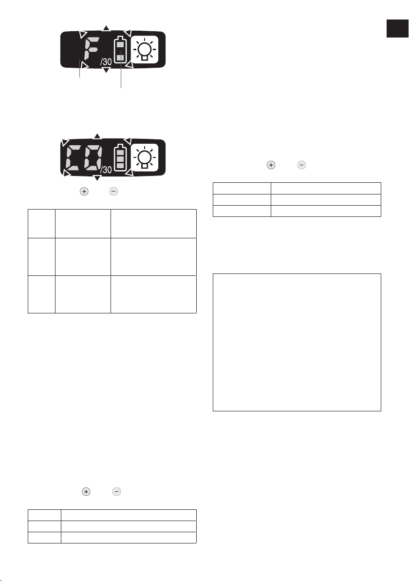
Radio signal range limitation function on/off setting
(EYFPA1JR)
1. Set the tool to configuration mode.
(See page 11.)
2. Press the C button three times.
• The control panel will begin flashing.
Display: The letter “F” ashes on and off.
Battery indication lamp: The upper and
lower bars of the battery ash on and off.
-
-
4. Press the OK button to accept the new
setting.
-
14 -
Display
Battery indication lamp
3. Press the C button again.
• Radio signal range limitation function
on/off setting value will be displayed.
4. Press the and buttons to set radio
signal range limitation function on/off.
Display
Factory settings
Radio signal
range limitation
function mode
Tool is operational in the
C0 OFF
C1 ON
• Radio signal range limitation function
setting: C0 (OFF)
NOTE:
• For more information about how to reg
ister the tool and Assembly Qualifier,
see the Assembly Qualifier instruction
manual.
absence of communications with the Assembly
Qualier.
Tool is not operational
in the absence of communications with the As-
sembly Qualier.
Status
LED light setting
• You can select from two LED light modes.
1. Set the tool to setting configuration mode.
(See page 11.)
2. Press the B button once.
• The current setting value will be dis
played.
3. Press the
desired value.
Display Function
d1 Linked to LED light button
d2
and buttons to set the
Linked to trigger switch operation
4. Press the OK button to accept the new
setting.
NOTE:
• The tool ships with the LED light mode
set to d1 by default.
Speed control function
• The speed (RPM) can be changed with the
amount of depression of the trigger.
1. Set the tool to setting configuration mode.
(See page 11.)
2. Press the B button three times.
• The setting value will be displayed.
3. Press the
desired value.
Operation Function
P0 Speed control ON
P1 Speed control OFF
Press the OK button to accept the new set-
4.
ting.
and buttons to set the
Initializing all settings
Factory settings
• Torque clutch setting: “F” (torque con
trol function off)
• Snug point detection level → L1
• Cross thread reduction function → R0
• Rundown error detecting function → 0
• Maintenance interval alarm function
→ 0
• Radio signal range limitation function
-
-
→ C0
• Buzzer setting → b0
• LED light setting → d1
• Speed control setting → P0
• This section explains how to revert all tool
settings to their default values at the time of
shipment from the factory.
• The error display will be turned off.
1. Set the tool to the setting configuration
mode.
(See page 11.)
2. Press the C button.
• The control panel will begin flashing.
Display: The letter “F” ashes on and off.
Battery indication lamp: The upper and
lower bars of the battery ash on and off.
-
-
15 -
EN EN
Checking the status of the
LED light and rundown error
detecting function and speed
control function settings
Display
Battery indication lamp
3. Press the OK button to accept the selected setting.
• The control panel will stop flashing and
light up.
1. Press the B button.
• The LED light and tightening time and
speed control setting will be displayed
(in that order).
Example: If the LED light mode is set to
L1 and the tightening time is set to 20
and speed control is set to ON,
“d1” → “20” → P0
Checking tool settings
• When the tool stops, the current setting
value will be displayed for approximately 2
seconds.
• The setting status cannot be checked while
the tool panel is off. Depress the trigger
switch once to turn on the panel.
Checking the status of the
torque clutch and sung point
detection level setting and
Buzzer settings
1. Press the A button.
• The torque clutch and sung point detec
tion level setting and buzzer setting values will be displayed (in that order).
Example: If the torque clutch is set to 30
and sung point detection level setting
L1 and the buzzer is set to sound at the
green indicator, “30” → “L1” → “b1”
Checking the tool circuits and
the status of the cross thread
reduction function and auto
downshift function settings
1. Press the D button.
• The tool circuits and cross thread reduc
tion function and auto downshift function
settings will be displayed (in that order).
Eample: “H3” → “R1” → “10”
Display Tool circuit
H2
-
NOTE:
• When other tools are in the area which
are not set, they may accidentally
receive a signal when setting the tool
by remote control.
Set the tool in another room if possible
or keep a fair distance to avoid this situation.
EYFPA1
-
-
16 -
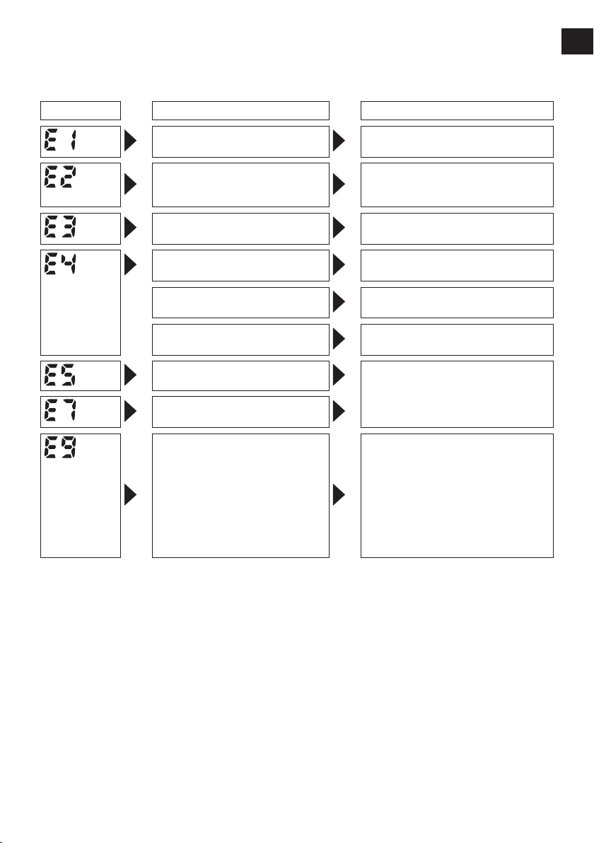
Error Display
In the event of a tool or battery pack malfunction, the control panel will display an error message.
Please check the tool or battery pack as described in the following chart before having them
serviced.
Display Likely cause Corrective action
Setting error Re-initialize the tool using the
The battery pack is too hot. Stop work and allow the battery
The tool is too hot to operate. Stop work and allow the tool to
The contacts that connect the
battery pack and tool are dirty.
The battery pack has not been
properly inserted into the tool.
The pins on either the tool or
battery pack have worn down.
Overload, Motor failure. etc. Stop using the tool immediately.
Tool circuit malfunction, failure,
etc.
The tool is unable to communicate with the Assembly Quali-
er while the radio signal range
limitation function is on.
remote control. (See page 15.)
pack to cool before resuming use
of the tool.
cool before resuming use.
Remove any dirt.
Insert the battery pack rmly into
the tool.
Replace the battery pack.
• Verify that the tool has been
properly registered to the Assembly Qualifier.
Verify that the Assembly Qualifi-
•
er’s group setting has been configured correctly.
Improve the reception state, for
•
example by moving the Assembly Qualifier closer to the tool.
NOTE:
• When the tightened bolt is further tightened or loosened, the overload protection function (E5)
may be activated.
17 -
-

-
18 -
EN EN
[Battery Pack]
For Appropriate Use of Bat-
tery Pack
Li-ion Battery Pack
• For optimum battery life, store the Li-ion battery pack following use without charging it.
• When charging the battery pack, confirm
that the terminals on the battery charger
are free of foreign substances such as dust
and water etc. Clean the terminals before
charging the battery pack if any foreign substances are found on the terminals.
The life of the battery pack terminals may be
affected by foreign substances such as dust
and water etc. during operation.
• When battery pack is not in use, keep it
away from other metal objects like: paper
clips, coins, keys, nails, screws, or other
sm all m eta l obj ect s th at can m ake a
connection from one terminal to another.
Shorting the battery terminals together may
cause sparks, burns or a fire.
• When operating the battery pack, make sure
the work place is well ventilated.
• When the battery pack is removed from the
main body of the tool, replace the battery
pack cover immediately in order to prevent
dust or dirt from contaminating the battery
terminals and causing a short circuit.
See the illustration
14
Battery Pack Life
The rechargeable batteries have a limited life.
If the operation time becomes extremely short
after recharging, replace the battery pack with
a new one.
Battery Recycling
ATTENTION:
A Li-ion battery that is recyclable powers
the product you have purchased.
Please call 1-800-8-BATTERY for information on how to recycle this battery.
[Battery Charger]
The recommended charg-
ing process
Read the operating manual for Panasonic battery charger for the battery pack before charging.
Charge the battery at a temperature of 5°C
(41°F) to 40°C (104°F).
The battery pack cannot be charged at a
temperature of less than 5°C (41°F). If the
temperature of the battery pack is less than
5°C (41°F), keep the battery pack for an hour
in a location where the temperature is 5°C
(41°F) or warmer before charging.
VI
. MAINTENANCE
Use only a dry, soft cloth for wiping the unit. Do not use a damp cloth, thinner, benzine, or other
volatile solvents for cleaning.
 Loading...