

Panasonic EYFPA1C, EYFNA1J, EYFPA1J, EYFNA1C Operating Instructions Manual
Operating Instructions
Bedienungsanleitung
Instructions d’utilisation
Istruzioni per l’uso
Gebruiksaanwijzing
Manual de instrucciones
Brugsvejledning
Driftsföreskrifter
Bruksanvisning
Käyttöohjeet
Instrukcja obsługi
Kullanım talimatları
Model No: EYFPA1C / EYFPA1J
EYFNA1C / EYFNA1J
Cordless Impact Wrench
Akku-Schlagschrauber
Clé de serrage à impact sans l
Chiave ad impulsi senza li
Snoerloze slagmoersleutel
Llave de impacto inalámbrica
Akku-slagnøgle
Sladdlös slagskruvnyckel
Trådløs slagnøkkel
Langaton iskuavain
Bezprzewodowy klucz udarowy
Kablosuz Darbeli Anahtar
Before operating this unit, please read these instructions completely and save this manual for future use.
Vor Inbetriebnahme des Gerätes die Betriebsanleitung bitte gründlich durchlesen und diese Broschüre zum späteren Nachschlagen sorgfältig
aufbewahren.
Lire entièrement les instructions suivantes avant de faire fonctionner l’appareil et conserver ce mode d’emploi à des fins de consultation
ultérieure.
Prima di usare questa unità, leggere completamente queste istruzioni e conservare il manuale per usi futuri.
Lees deze gebruiksaanwijzing aandachtig door voor u het apparaat in gebruik neemt en bewaar de gebruiksaanwijzing voor eventuele naslag.
Antes de usar este aparato por primera vez, lea todas las instrucciones de este manual y guarde el manual para poderlo consultar en el futuro.
Gennemlæs denne betjeningsvejledning før brugen og gem den til fremtidig brug.
Läs igenom hela bruksanvisningen innan verktyget tas i bruk. Spara bruksanvisningen för senare användning.
Før enheten tas i bruk, vennligst les disse alle anvisningene og oppbevar deretter bruksanvisningen for senere bruk.
Lue ohjeet huolella ennen laitteen käyttöönottoa ja säilytä tämä käyttöohje tallessa tulevaa tarvetta varten.
Przed uruchomieniem urządzenia należy przeczytać w całości niniejszą instrukcję i zachować ten podręcznik do użytku w przyszłości.
Bu cihazı kullanmaya başlamadan önce, lütfen bu talimatları tam olarak okuyun ve ileride başvurmak üzere bu kılavuzu saklayın.
EYFPA1J
-
2 -
FUNCTIONAL DESCRIPTION
FUNKTIONSBESCHREIBUNG
DESCRIPTION DES FONCTIONS
DESCRIZIONE DELLE FUNZIONI
FUNCTIEBESCHRIJVING
DESCRIPCIÓN FUNCIONAL
FUNKTIONSBESKRIVELSE
FUNKTIONSBESKRIVNING
FUNKSJONSBESKRIVELSE
TOIMINTAKUVAUS
OPIS FUNKCJI
İŞLEVSEL AÇIKLAMA
(C)
(D)
(J)
(K)
(E)
(F)
(Y)
(X)
(W)
EYFA30
(M)
(N)
(O)
(V)
EYFA31
A
B
C D
(M)
(N)
(O)
(L)
(P)
(S)
(R)
(Q)
(U)
(T)
EYFA31
Index/Index/Index/Indice/Index/Indice/Indeks/Index/Indeks/Hakemisto/Indeks/Dizin
English: Page 9 Dansk: Side 95
Deutsch: Seite 24 Svenska: Sid 109
Français: Page 38 Norsk: Side 123
Italiano: Pagina 52 Suomi: Sivu 137
Nederlands: Bladzijde 66 Polski: Strona 151
Español: Página 80 Türkçe: Sayfa 165
Remote control and battery are not included.
Fernbedienung und Batterie werden nicht
mitgeliefert.
La télécommande et la batterie ne sont pas
incluses.
Telecomando e batteria non in dotazione.
Afstandsbediening en batterij zijn niet bij-
geleverd.
El control remoto y la batería no están in-
cluídos.
Fjernbetjening og batteri medfølger ikke.
Fjärrkontroll och batteri medföljer ej.
Fjernkontroll og batteri er ikke inkludert.
Kaukosäädin ja paristo eivät kuulu varus-
teisiin.
Zestaw nie zawiera zdalnego sterowania i
akumulatora.
Uzaktan kumanda ve pil dahil değildir.
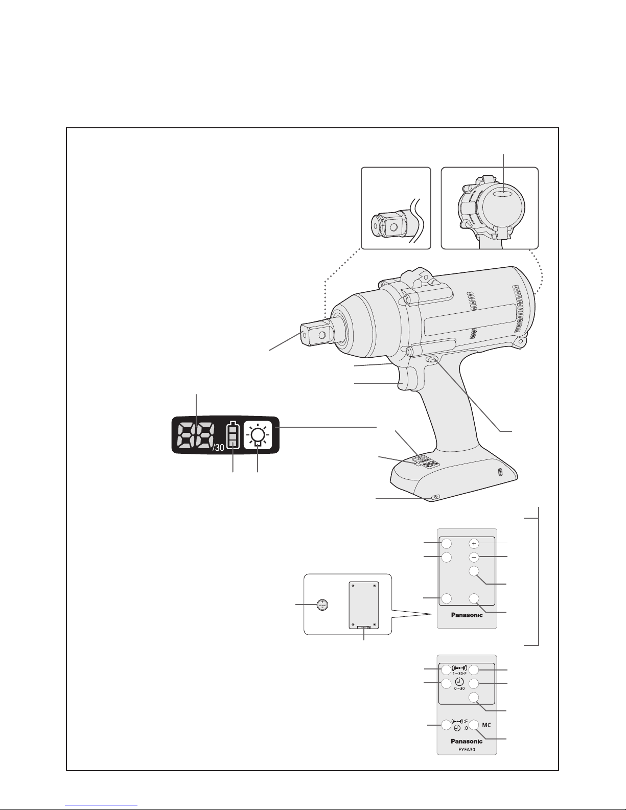
(B)
(A)-1
EYFPA1J
EYFNA1J
(G)(H)
(I)
EYFPA1C
EYFNA1C
(A)-2

-
3 -
(A)-1
Square drive (pin type)
Vierkant (stifttyp)
Entraînement carré (type à goujon)
Attacco quadro (tipo con piolo)
Vierkante aandrijving (pen-type)
Excitador cuadrado (tipo pasador)
Firkantet drev (stifttype)
Fyrkantskoppling (stifttyp)
Firkantdrev (pinnetype)
Neliöavain (nastatyyppi)
Kwadratowa końcówka (typ wtyk)
Kare tornavida (pim tipi)
(
A
)-2
Square drive (retainer ring and pin)
Vierkant (Haltering und Stift)
Entraînement carré (anneau de retenue et goupille)
Attacco quadro (anello di ritenzione e spinotto)
Vierkante aandrijving (borgring en pen)
Excitador cuadrado (anillo retenedor y pasador)
Firkantet drev (låsering og stift)
Fyrkantskoppling (stoppring och sprint)
Firkantdrev (låsering og tapp)
Neliöavain (lukitusrengas ja nasta)
Kwadratowa końcówka (pierścień zabezpieczający i sworzeń)
Kare tornavida (tespit halkası ve pim)
(B)
Tightening conrmation lamp
Anzugsbestätigungslampe
Témoin de conrmation de serrage
Spia conferma serraggio
Aanhaaltoestand-bevestigingslampje
Lámpara de conrmación de apriete
Lampe til bekræftelse af stramning
Lampa för bekräftad åtdragning
Strammebekreftelseslampe
Kiristyksen varmistuslamppu
Lampka potwierdzenia dokręcenia
Sıkma onay lambası
(C)
Forward/Reverse lever
Vorwärts-/Rückwärtshebel
Levier d’inversion marche avant/marche arrière
Leva di avanzamento/inversione
Links/rechtsschakelaar
Palanca de avance/marcha atrás
Greb til forlæns/baglæns retning
Riktningsomkopplare
Forover-/bakoverbryter
Eteenpäin/taaksepäin vipu
Dźwignia biegu do przodu/wstecznego
İleri/Geri kolu
(D)
Alignment mark
Ausrichtmarkierungen
Marques d’alignement
Marcature allineamento
Uitlijntekens
Marcas de alineación
Flugtemærker
Anpassningsmärken
Opprettingsmerke
Sovitusmerkit
Znak ustawczy
Hizalama işareti
(E)
Remote control receiver
Fernbedienungsempfänger
Récepteur de la télécommande
Ricevitore telecomando
Afstandsbedieningontvanger
Receptor de control remoto
Fjernbetjeningsmodtager
Fjärrstyrningsgivare
Fjernkontrollmottaker
Kaukosäätimen vastaanotin
Odbiornik zdalnego sterowania
Uzaktan kumanda alıcısı
(F)
Control panel
Bedienfeld
Panneau de commande
Pannello di controllo
Bedieningspaneel
Panel de control
Kontrolpanel
Kontrollpanel
Kontrollpanel
Säätöpaneeli
Panel sterowania
Kontrol paneli
(G)
LED light on/off button
LED-Leuchten-EIN/AUS-Taste
Bouton Marche/Arrêt de la lumière DEL
Tasto di accensione e spegnimento della luce LED
Aan/uit-toets (ON/OFF) voor LED-lampje
Botón ON/OFF de luz LED
TÆND/SLUK-knap til LED-lys
Strömbrytare för LED-ljus
PÅ/AV-knapp for LED-lys
LED-valon kytkin/katkaisupainike
Przycisk włączania/wyłączania diody LED
LED ışık açma/kapama düğmesi
(H)
Battery indication lamp
Akku-Anzeigelampe
Témoin indicateur de la batterie
Spia livello batteria
Accu-indicatielampje
Lámpara de indicadora de la batería
Batteriindikatorlampe
Batteriindikator
Batteriindikasjonslampe
Akun osoituslamppu
Wskaźnik poziomu mocy akumulatora
Pil gösterge lambası
(I)
Display
Anzeige
Afchage
Display
Display
Visor
Display
Indikeringsfönster
Display
Näyttö
Ekran
Ekran

-
4 -
(J)
Variable speed control trigger
Variabler Geschwindigkeitskontrollschalter
Gâchette de commande de vitesse
Grilletto di controllo velocità variabile
Startschakelaar met variabele toerentalregeling
Disparador del control de velocidad variable
Kontroludløser for variabel hastighed
Avtryckare med variabel varvtalsreglering
Trinnløs hovedbryter
Nopeudensäätökytkin
Zapadka regulacji prędkości obrotowej
Değişken hız kontrol tetiği
(K)
LED light
LED-Leuchte
Lumière DEL
Luce LED
LED-lampje
Luz indicadora
LED-lys
LED-ljus
LED-lys
LED-valo
Dioda LED
LED ışık
(L)
Remote control
Fernbedienung
Télécommande
Telecomando
Afstandsbediening
Control remoto
Fjernbetjening
Fjärrkontroll
Fjernkontroll
Kaukosäädin
Zdalne sterowanie
Uzaktan kumanda
(M)
+ button
Taste +
Bouton +
Tasto +
+ toets
Botón +
+ knap
Knapp (+)
+ knapp
+ painike
Przycisk +
+ düğmesi
(N)
− button
Taste –
Bouton −
Tasto −
− toets
Botón −
− knap
Knapp (−)
− knapp
− painike
Przycisk −
− düğmesi
(O)
OK button
Taste OK
Bouton OK
Tasto OK
OK toets
Botón OK (correcto)
OK-knap
Bekräftelseknapp
OK knapp
OK-painike
Przycisk OK
Tamam düğmesi
(P)
D button
Taste D
Bouton D
Tasto D
D-toets
Botón D
D-knap
D-knapp
D-knapp
D-painike
Przycisk D
D düğmesi
(Q)
C button
Taste C
Bouton C
Tasto C
C-toets
Botón C
C-knap
C-knapp
C-knapp
C-painike
Przycisk C
C düğmesi
(R)
B button
Taste B
Bouton B
Tasto B
B-toets
Botón B
B-knap
B-knapp
B-knapp
B-painike
Przycisk B
B düğmesi
(S)
A button
Taste A
Bouton A
Tasto A
A-toets
Botón A
A-knap
A-knapp
A-knapp
A-painike
Przycisk A
A düğmesi

-
5 -
(T)
Holder
Halter
Support
Supporto
Houder
Retenedor
Holder
Hållare
Holder
Pidin
Uchwyt
Tutucu
(U)
Battery
Batterie
Batterie
Batteria
Accu
Batería
Batteri
Batteri
Batteri
Akku
Akumulator
Pil
(V)
Torque level button
Anzugsmomentstufentaste
Bouton de niveau du couple de serrage
Tasto livello coppia
Aanhaalmoment-niveautoets
Botón de palanca de par de torsión
Knap til stramningsmomentniveau
Väljare för momentnivå
Dreiemomentknapp
Vääntömomentin tasopainike
Przycisk poziomu momentu obrotowego
Tork seviyesi düğmesi
(W)
Format button
Formattaste
Bouton de format
Tasto formato
Formatteertoets
Botón de formato
Formatknap
Formateringsknapp
Format knapp
Formaatin painike
Przycisk formatu
Biçim düğmesi
(X)
Interval set button
Intervall-Einstelltaste
Bouton de réglage de l’intervalle
Tasto impostazione intervallo
Interval-insteltoets
Botón de ajuste de intervalo
Intervalindstillingsknap
Intervallinställningsknapp
Intervallinnstillingsknapp
Jakson säätöpainike
Przycisk regulacji interwału
Aralık ayar düğmesi
(Y)
Torque set button
Anzugsmoment-Einstelltaste
Bouton de réglage du couple de serrage
Tasto impostazione coppia
Aanhaalmoment-insteltoets
Botón de ajuste de par de torsión
Knap til indstilling af stramningsmoment
Momentinställningsknapp
Dreiemomentinnstillingsknapp
Vääntömomentin säätöpainike
Przycisk regulacji momentu obrotowego
Tork ayar düğmesi
-
6 -
[Fig.9]
[Fig.1]
rubber ring
Gummiring
anneau en caoutchouc
anello di gomma
rubberring
anillo de caucho
gummiring
Gummiring
gummiring
kumirengas
gumowy pierścień
lastik halka
pin
Stift
goupille
piolo
pen
pasador
stift
Sprint
pinne
nasta
wtyk
pim
groove
Nut
rainure
scanalatura
groef
ranura
rille
Spår
spor
vako
rowek
yiv
Illustrations/Abbildungen/Illustrations/Illustrazioni/Afbeeldingen/Imágenes/
Illustrationer/Illustrationer/Illustrasjoner/Kuvat/Ilustracje/Resimler
[Fig.2]
[Fig.3]
[Fig.4]
[Fig.5]
[Fig.6]
[Fig.7]
[Fig.8]

-
7 -
Approx. 60°
ca. 60°
Environ 60°
Circa 60°
Ongeveer 60°
Aprox. 60°
Ca. 60°
Ca 60°
Ca. 60°
Noin 60°
Ok. 60°
Yaklaşık 60°
Approx. 50 cm
ca. 50 cm
Environ 50 cm
Circa 50 cm
Ongeveer 50 cm
Aprox. 50 cm
Ca. 50 cm
Ca 50 cm
Ca. 50 cm
Noin 50 cm
Ok. 50 cm
Yaklaşık 50 cm
[Fig.10]
Vertically
A
p
p
r
o
x
.
6
0
°
A
p
p
r
o
x
.
6
0
°
Approx. 50 cm
Vertically
Vertikal
Verticalement
Senso verticale
Verticaal
Verticalmente
Lodret
Vertikalt
Vertikalt
Pystysuorassa
Pionowo
Dikey
[Fig.12]
[Fig.11]
[Fig.13]
(1) (2) (3)
[Fig.14]
Forward
Rechts
Rotation en
sens normal
Avanti
Rechts
Avance
Forlæns
Framåt
Forover
Eteenpäin
Do przodu
İleri
Reverse
Links
Rotation en
sens inverse
Inversione
Links
Marcha atrás
Baglæns
Bakåt
Bakover
Taaksepäin
Wstecz
Geri
Switch lock
Schaltersperre
Verrouillage de
commutateur
Blocco interruttore
Vergrendelstand
Bloqueo del
interruptor
Omskifterlås
Låst läge
Bryterlås
Kytkinlukko
Blokada
przełącznika
Şalter kilidi
-
8 -
[Fig.15]
[Fig.17]
A
B
(2)
(3)
(1)
[Fig.18]
[Fig.19]
[Fig.20]
EYFA31
A
B
C D
(1)
(2)
Display
Anzeige
Afchage
Display
Display
Visor
Display
Indikeringsfönster
Display
Näyttö
Ekran
Ekran
Battery indication lamp
Akku-Anzeigelampe
Témoin indicateur de la
batterie
Spia livello batteria
Accu-indicatielampje
Lámpara de indicadora
de la batería
Batteriindikatorlampe
Batteriindikator
Batteriindikasjonslampe
Akun osoituslamppu
Wskaźnik poziomu mocy
akumulatora
Pil gösterge lambası
[Fig.16]

-
9 -
Original instructions: English
Translation of the original instructions:
Other languages
I
. INTENDED USE
This tool is a Cordless Impact Wrench and can
be used to tighten bolts, nuts, and screws. Additionally, it provides a torque control function
that automatically stops tool operation when
a preset load is reached to deliver consistent
tightening torque.
IMPROPER USE
The use of the tool other than INTENDED USE
is dangerous and must be avoided.
The tool must not be used for the purposes
such as the following;
• to mix paint or building materials,
• polishing, grinding, sharpening, engraving.
RESIDUAL RISK
Some residual risks remains even with proper
use of the tool such as the following;
• contact with the rotating bit
• contact with the sharp edges of material or
something.
Read “the Safety Instructions” booklet
and the following before using.
II
.
ADDITIONAL SAFETY
RULES
1) If the bit becomes jammed, immediate-
ly turn the trigger switch off to prevent
an overload, which can damage the battery pack or motor. Use reverse motion to
loosen jammed bits.
2) Do NOT operate the Forward/Reverse
lever when the trigger switch is on. The
battery will discharge rapidly and damage
to the unit may occur.
3) During charging, the charger may become
slightly warm. This is normal. Do NOT
charge the battery for a long period.
4) Do not strain the tool by holding the speed
control trigger halfway (speed control
mode) so that the motor stops.
5) To prevent injury during use, hold the tool
steady at all times and avoid waving it
around.
6) Make certain that there are no hidden
gas or water pipes, or electrical wires in
the area where you will be working. Coming into contact with hidden pipes or wires
could result in electric shock, or water or
gas leaks.
7) Make sure to hold the object you are
working on steady.
8) Check for damaged parts.
• Check thoroughly for damage to the
protective cover and other parts before
operating.
• Check to make sure the tool and all of
its functions are working properly.
• Check the adjustment of all movable
parts, and check all fixed parts to make
sure they are fitted properly and free of
damage. Check all parts of the tool for
abnormal function.
9) When attempting to repair the protec
tive cover or other parts, please follow the
instructions in the user manual. In cases
where there are no instructions in the
manual, please take it back to the store to
have it repaired.
10) If the tool gets exceptionally hot dur
ing use, please take it in for service and
repair.
11) To avoid potential injury, keep face and
hands away from the drill bit and any
shavings.
12) Do not wear gloves when operating the
tool, as they may get caught by the drill,
leading to injury.
13) Battery terminals, screw shavings, and
tool accessories such as drill bits will be
very hot immediately after operation. Do
not touch them as there is a risk of burning yourself.
-
10 -
EN EN
WARNING
Do not use other than the Panasonic battery packs that are designed for use with
this rechargeable tool.
Panasonic is not responsible for any damage or accident caused by the use of
recycled or counterfeit battery pack.
Do not dispose of the battery pack in a
fire, or expose it to excessive heat.
Do not allow metal objects to touch the
battery pack terminals.
Do not carry or store the battery pack
in the same container as nails or similar
metal objects.
Do not charge the battery pack in a
high-temperature location, such as next
to a fire or in direct sunlight. Otherwise,
the battery may overheat, catch fire, or
explode.
After removing the battery pack from the
tool or the charger, always reattach the
pack cover. Otherwise, the battery contacts could be shorted, leading to a risk
of fire.
When the Battery Pack Has Deteriorated,
Replace It with a New One. Continued
use of a damaged battery pack may result
in heat generation, ignition or battery rupture.
To prevent leakage, overheating, smoke
generation, fire, and rupturing from occurring, follow these instructions when handling our rechargeable power tools (tool
main body/battery pack/charger).
Do not allow material cuttings or dust to
fall onto the battery pack.
When storing, remove any material cuttings and dust from the battery pack,
and place the battery pack separately
from metal objects (screws, nails, etc.)
when storing in the tool case.
Do not handle the rechargeable power
tools in the following way.
(There is a hazard of smoke generation,
fire, and rupturing)
Use or leave in places exposed to rain
or moisture
Use submerging in water
•
•
•
•
•
•
•
•
•
-
-
•
-
-
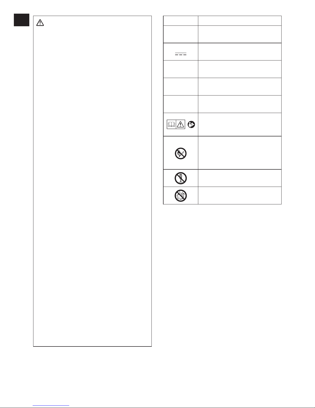
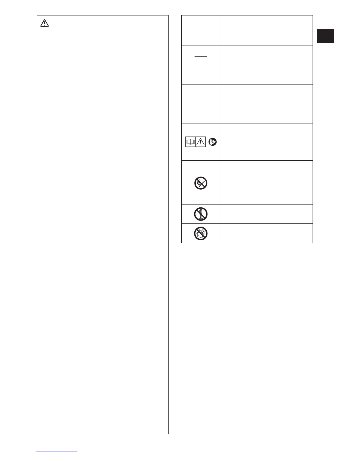
Symbol Meaning
V
Volts
Direct current
n
0
No load speed
… min
-1
Revolutions or reciprocations
per minutes
Ah
Electrical capacity of battery
pack
To reduce the risk of
injury, user must read and
understand instruction manual.
Do not incinerate or heat bat-
tery pack. Do not charge or
use under conditions of high
temperature. Do not expose to
high temperatures.
Do not disassemble or modify.
Do not expose to rain or water.
III
. ASSEMBLY
CAUTION:
Make sure that the socket, extension
or any attachment used with the tool to
hold fasteners is designed specifically
for power tools (Impacting tools).
Using the tool with attachments designed
for hand tools may break the attachments and cause possible danger.
Also, Make sure that there is nothing
wrong on the attachment before operating.
NOTE:
If a worn or deformed socket is used,
the square drive (retainer ring and pin)
may not enter the socket properly.
-
11 -
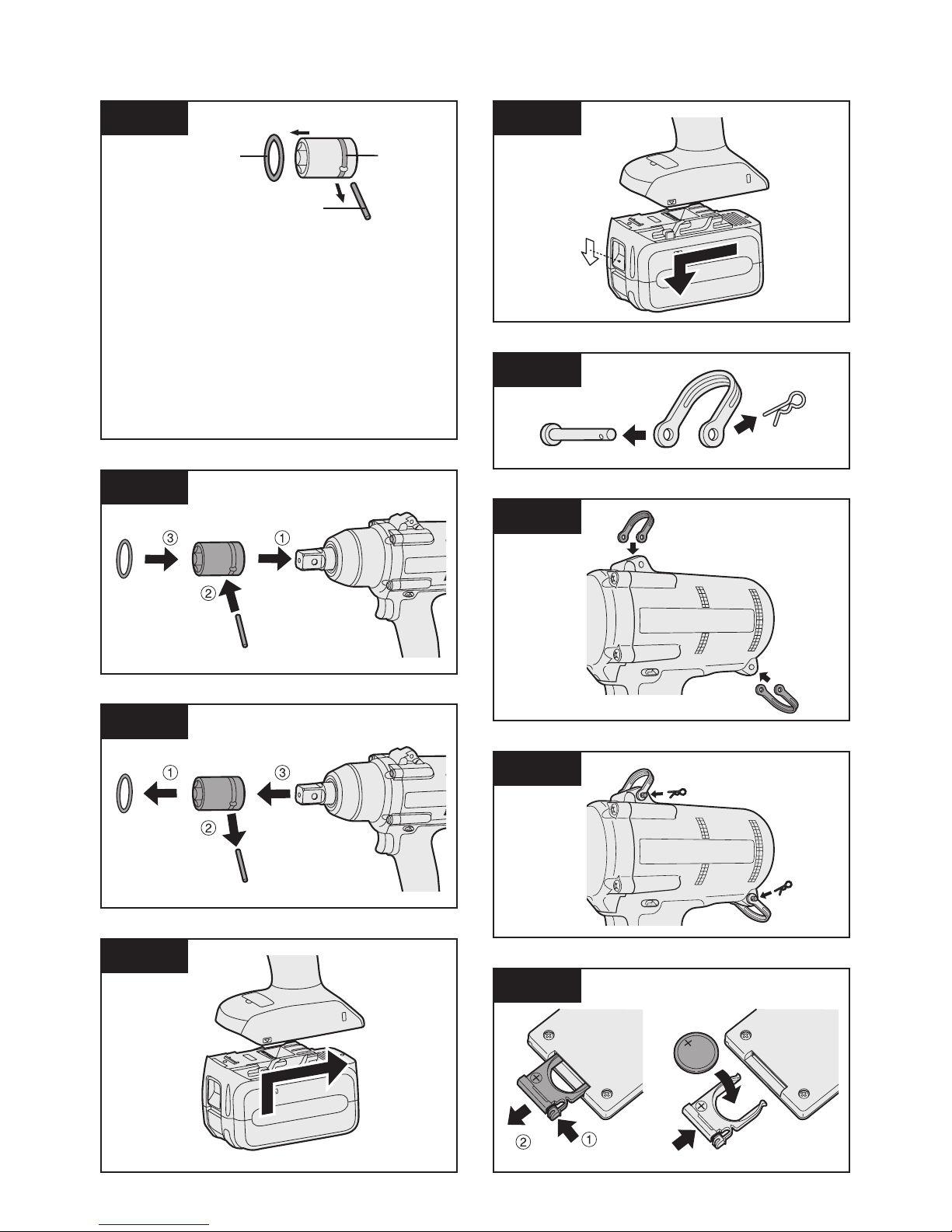
Attaching Socket (Pin type)
Remove the socket’s rubber ring and pin.
[Fig.1]
1 Attach the socket to the tool.
2 Insert the pin. (Taking care to align the pin
holes on the socket and tool.)
3 Attach the rubber ring by sliding it into
place over the groove.
[Fig.2]
NOTE:
Be sure to attach the rubber ring to prevent the pin from falling out.
Removing Socket (Pin type)
1 Remove the rubber ring.
2 Remove the pin.
3 Remove the socket from the tool.
[Fig.3]
NOTE:
Keep the temperature of the tool above
the freezing point (0°C/32°F) when
attaching sockets to or removing them
from the square drive on the tool. Do
not use excessive force when attaching
or removing sockets.
Attaching or Removing Bat
tery Pack
1. To connect the battery pack:
Line up the alignment marks and attach
the battery pack.
Slide the battery pack until it locks into
position.
[Fig.4]
2. To remove the battery pack:
Push down the button and slide the battery
pack forward.
[Fig.5]
Attaching the tool hanger
1. Remove the pin and the clip from the tool
hanger.
[Fig.6]
2. Align the holes on the tool hanger with the
holes on the tool body.
[Fig.7]
3. Insert the pin into the holes on the tool
hanger and the tool body.
Attach the clip on the tool hanger's holes.
[Fig.8]
IV
. OPERATION
WARNING
Do not inhale any smoke emitted from the
tool or battery pack as it may be harmful.
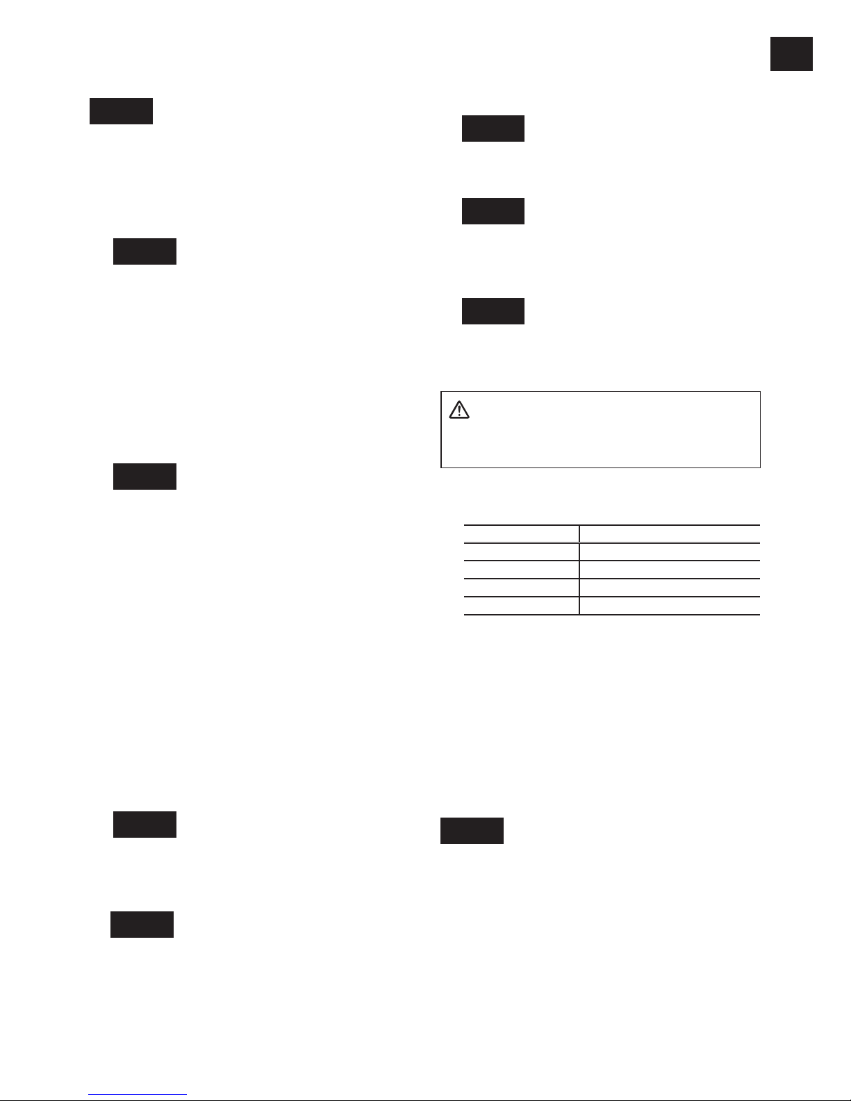
Comparison chart for EYFA31 / EYFA30
remote control
EYFA31 EYFA30
D button (P) Torque level button (V)
C button (Q) Format button (W)
B button (R) Interval set button (X)
A button (S) Torque set button (Y)
This operating instruction is written with
the contents of EYFA31 model.
In the case of use with EYFA30, refer to
the above chart and replace EYFA30 with
EYFA31.
Before Using the Remote
Control (Available as an
optional accessory)
[Fig.9]
Insert the battery
1. Pull out the battery holder.
1 Push in on the fastener as indicated by the
arrow.
2 Pull out the holder.
2. Insert the battery and push the holder
back in.

-
12 -
EN EN
NOTE:
If the tool does not respond to the wireless remote control even when the
remote control is operated close to
the tool, the battery (CR2025) is dead.
Replace it with a fresh battery.
The included battery is provided for
sample use and may not last as long as
commercially available batteries.
Wireless remote control range
[Fig.10]
The remote control should be operated within
approximately 50 cm and approximately 60°
vertically and horizontally of the perpendicular
relative to the infrared receiver on the tool.
• Under the following circumstances, you may
not be able to operate the tool, even within
this range.
- If there is an object between the remote
control’s transmitter and the tool’s receiver.
- Use outdoors or in other environments
where the remote control receiver is
exposed to a strong light source, or when
the remote control transmitter or receiver is
dirty may cause the tool to fail to respond,
even when the remote control is used within
the operating range.
[Main Unit]
CAUTION:
If a tool holder is used with the
Panasonic EYF series assembly tools,
make sure the tool’s trigger switch
doesn’t hit the tool holder. It may run
the tool accidentally and result in battery
failure by unexpected battery discharge.
[Fig.11]
CAUTION:
When storing or carrying the tool, set
the Forward/Reverse lever to the center
position (switch lock).
NOTE:
Exercise caution to ensure no objects
come into contact with the tool’s trigger
switch.
If an object comes into contact with
the tool’s trigger switch, even while the
Forward/Reverse lever is in the center
position (locked), a small amount of
electric current may continue flowing,
•
•
which may cause an excessive discharge from the battery pack and subsequent battery pack failure.
Switch and Forward/Reverse
Lever Operation
[Fig.12]
1. Push the lever for forward or reverse rota
tion. Check the direction of the lever before
using.
2. Depress the trigger switch slightly to start
the tool slowly.
3. Speed will increase by pressing the trig
ger. The tool stops working immediately by
releasing the trigger.
4. When done with an application, lock the
switch by centering the lever.
NOTE:
The more the speed control trigger is
pulled, the higher the speed becomes.
CAUTION:
When operating the tool by pulling the
trigger, there may be a momentary lag
before rotation starts. This does not signal a malfunction.
* This lag occurs as the tool’s circuitry
starts up when the trigger is pulled for
the first time after installing a battery
pack or after the tool has not been
used for at least 1 minute (or at least 5
minutes when the LED is on). Rotation
will start without any lag during second and subsequent operations.
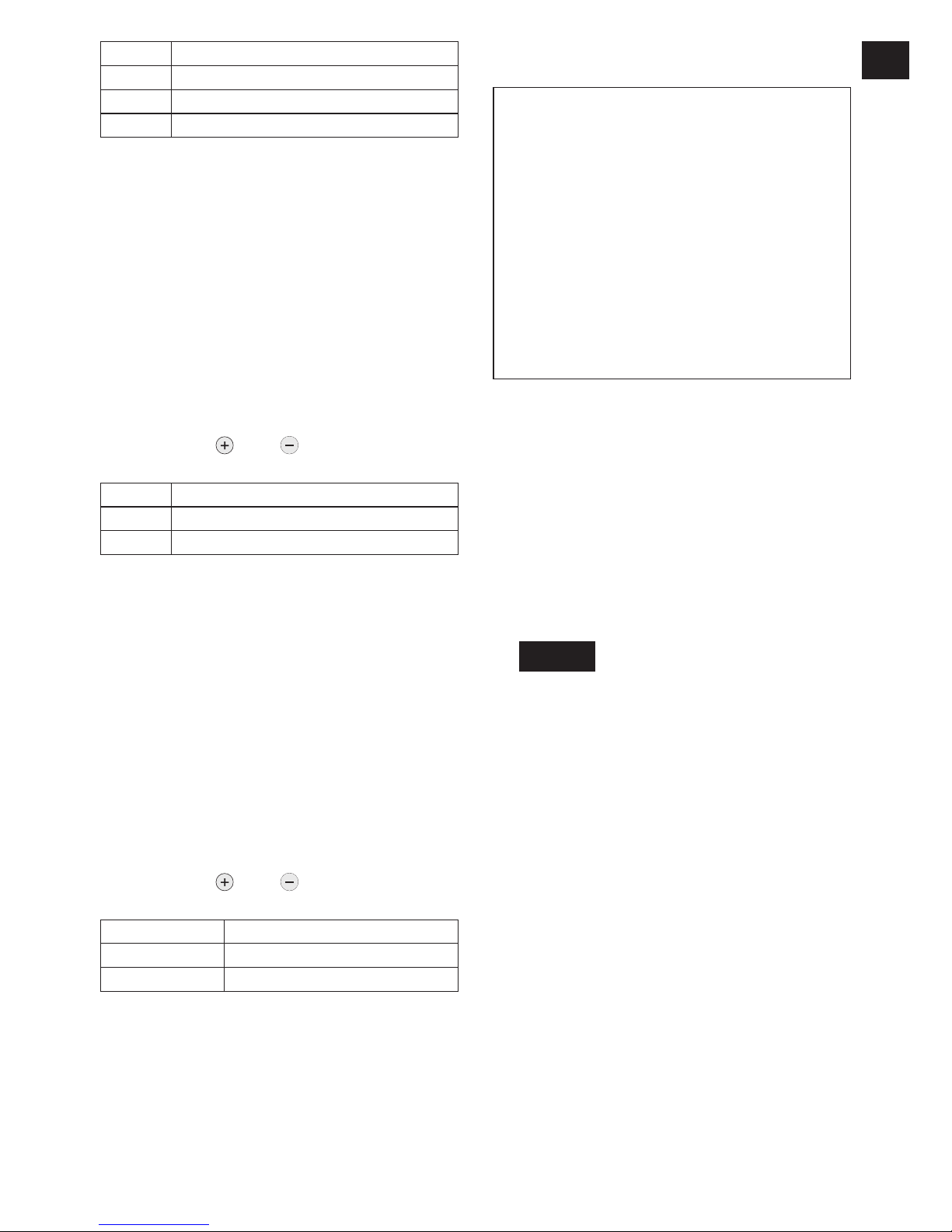
Tightening confirmation lamp
The tightening confirmation lamp can be used
to check whether the torque control function
was activated.
Tool status Lamp display
Tightening complete
(with torque control
function operation)
Green
(For approx. 2
seconds)
• Tightening not complete
• Tightening complete
with retightening within 1
second
Red
(For approx. 2
seconds)
The automatic stop
function has been
activated.
Red
(For approx. 5
minutes)
-
13 -
CAUTION:
When the tool stops automatically after
the switch is released during impactmode tightening and then reengaged
within 1 second, the red lamp will light up
to indicate the risk of excessive torque
application as a result of retightening.
NOTE:
The tightening confirmation lamp will not
turn on under the following conditions:
When the torque clutch is set to “F”
During reverse rotation operation
The lamp turns off when the tool is in
operation.
Control Panel
[Fig.13]
(1) The torque control function
The torque control function calculates the
load from the motor’s rotational angle during
the hammer impact and determines that the
bolt has been properly seated when a preset
load value is exceeded. Driving is then automatically stopped after a preset number of
impacts have been delivered to the bolt.
CAUTION:
Always check the tool’s tightening torque
before use. The required adjustment
is dependent on the type of threaded
connection and can be best determined
by practical trials. Check the trial screwings with a torque wrench. Improper tool
operation may result in excessive or
inadequate tightening.
Always operate the tool with the switch
fully depressed. The torque control function will not operate when the switch is
not sufficiently depressed, preventing
the tool from stopping automatically.
In work where a heavy load comes to
bear during tightening, the load may be
interpreted as the seating of the bolt,
preventing the bolt from being completely tightened.
Repeated tightening of the same bolt
may break the bolt or deform the material into which the bolt is being driven as
a result of excessive tightening.
•
•
•
•
•
•
•
•
The tightening torque value and precision vary with factors such as the material into which the bolt is being driven
and the condition of the socket being
used. Adjust the torque as necessary
for the work being performed. Bolt tightening torque varies due to the factors
described below.
1) Bolt
• Bolt diameter: Tightening torque
generally increases with bolt diameter.
• Torque coefficient (indicated by the
bolt manufacturer), grade, length,
etc.
2) Other
• Bit and socket condition: Material,
amount of play, etc.
• Use of a universal joint or socket
adapter
• User: Manner in which the tool
is applied to the bolt, strength
with which the tool is held, manner in which the tool’s switch is
depressed
• Condition of object being tightened:
Ma-terial, seating surface finish
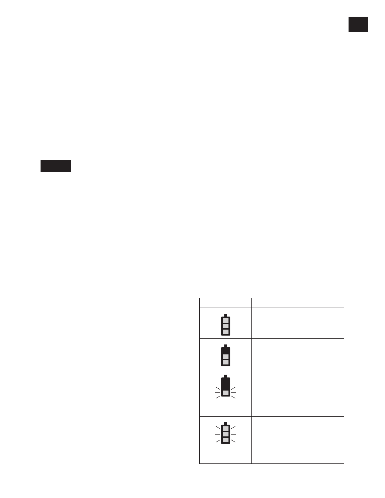
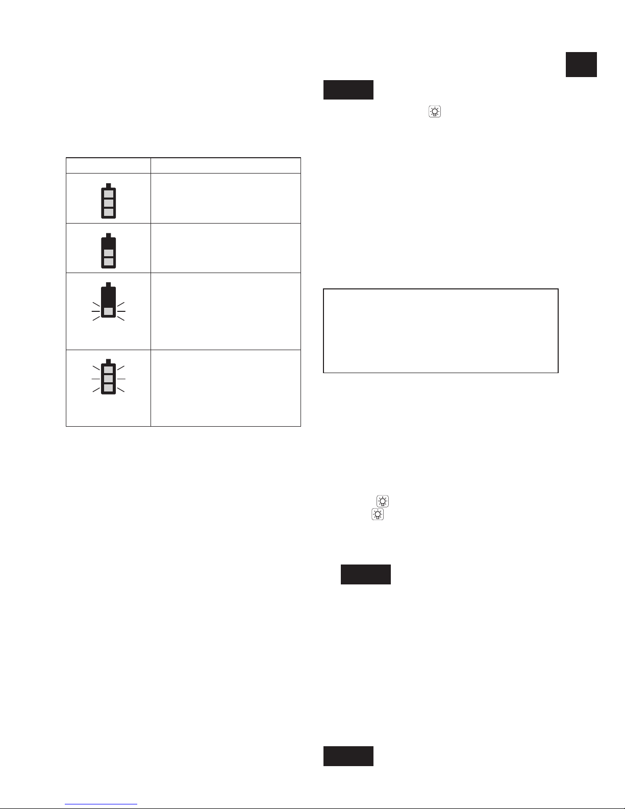
(2) The battery indication lamp
• Use the battery indication lamp to check
how much power is left in the battery.
• Battery life varies slightly with ambient temperature and battery characteristics. The
lamp is designed to provide a rough indication of remaining battery life.
Indicator Battery status
Fully charged
Approx. 40% or less
remaining
Flashing
Flashing
Approx. 20% or less
remaining (indicates need
to recharge battery)
The battery pack will need
to be charged soon.
Flashing
No charge
The battery pack needs to
be charged.
(The tool’s automatic
power-off function will
activate at this stage.)
•

-
14 -
EN EN
Automatic poweroff function
The automatic power-off function is designed
to prevent a loss of tightening torque due
to reduced battery voltage. Once it has
been activated, the tool will not operate until
the battery pack has been charged (or replaced with a fresh unit), even if the trigger is
depressed.
NOTE:
All 3 bars on the battery indication lamp
will flash when the automatic power-off
function is activated.
When the battery indication lamp begins
flashing, the battery pack should be
charged (or replaced with a fresh unit)
immediately.
Be sure to fully charge the battery pack
in question after activation of the automatic power-off function. Failure to do
so may prevent the automatic power-off
function from being properly deactivated.
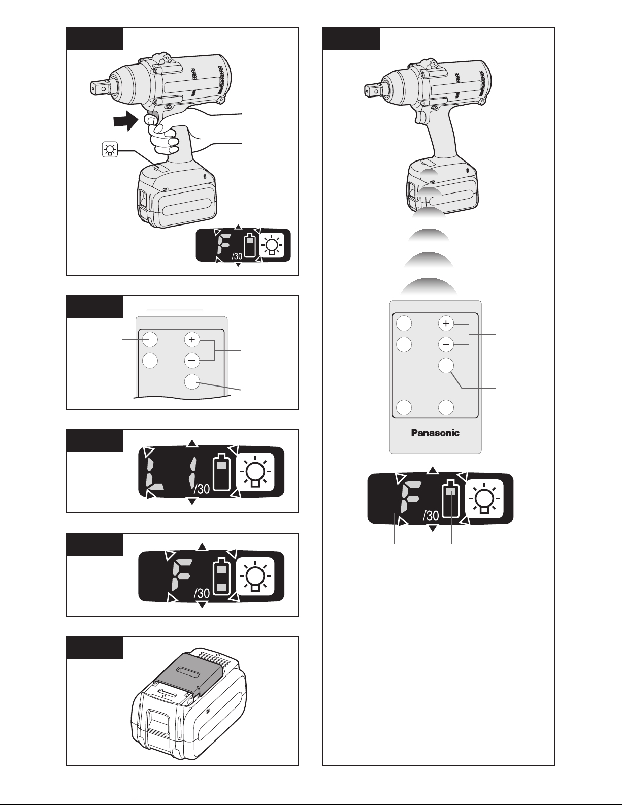
(3) LED light
This function is limited to “Linked to LED light
button.”
[Fig.14]
Pressing the button toggles the LED light
on and off.
The light illuminates with very low current, and
it does not adversely affect the performance of
the tool during use or its battery capacity.
CAUTION:
The built-in LED light is designed to illuminate the small work area temporarily.
Do not use it as a substitute for a regular flashlight, since it does not have
enough brightness.
Caution : DO NOT STARE INTO BEAM.
Use of controls or adjustments or performance
of procedures other than those specied herein
may result in hazardous radiation exposure.
Setting the tool to con-
figuration mode
1. Turn off the control panel.
If the control panel is on, remove and then
reinsert the battery pack.
•
•
•
•
•
2. Depress the switch while pushing the
button and then release both the button and the switch.
After all the LED lamps have turned off,
the control panel will flash and change to
configuration mode.
[Fig.15]
NOTE:
Tools ship from the factory set to “F”
mode (torque control function off).
The control panel will turn off if the tool
is not operated for a period of 5 minutes.
Configuring the torque clutch
setting
[Fig.16]
1. Press the
and buttons to select the
clutch setting that is appropriate for the
work being performed.
3…28
1F30 229
As the button
is pressed
As the button
is pressed
• “F” indicates that the torque control function is off.
• You can select from 30 torque clutch
settings (1 to 30).
• Use figures from the Tightening Torque
Chart to guide your selection of torque
clutch setting. (See the following tightening torque chart)
2. Press the OK button to accept the select
ed torque clutch setting.
The control panel will stop flashing and
light up.
CAUTION:
• You must press the OK button in order
for the selected setting to take effect.
• Be sure to verify the new value after
changing the setting.
•
•

-
15 -
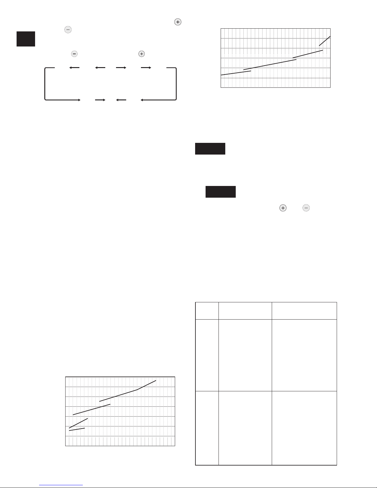
Tightening Torque Chart (for
reference use)
The values illustrated on this chart were measured under the conditions described below
and are provided for reference purposes.
Actual tightening torque varies with ambient
conditions (the particular bolt being tightened,
hardware being used, method of holding the
bolt in place, etc.).
700 (7140)
600 (6120)
500 (5100)
400 (4080)
300 (3060)
200 (2040)
100 (1020)
0
N·m (kgf·cm)
11 5 10 15 20 25 30
M24
M20
M18
M16
Torque setting level
Tightening torque
EYFPA1C, EYFPA1J
300 (3060)
250 (2550)
200 (2040)
150 (1530)
100 (1020)
50 (510)
0
N·m (kgf·cm)
11 5 10 15 20 25 30
M18
M16
M14
M12
Tightening torque
Torque setting level
EYFNA1C, EYFNA1J
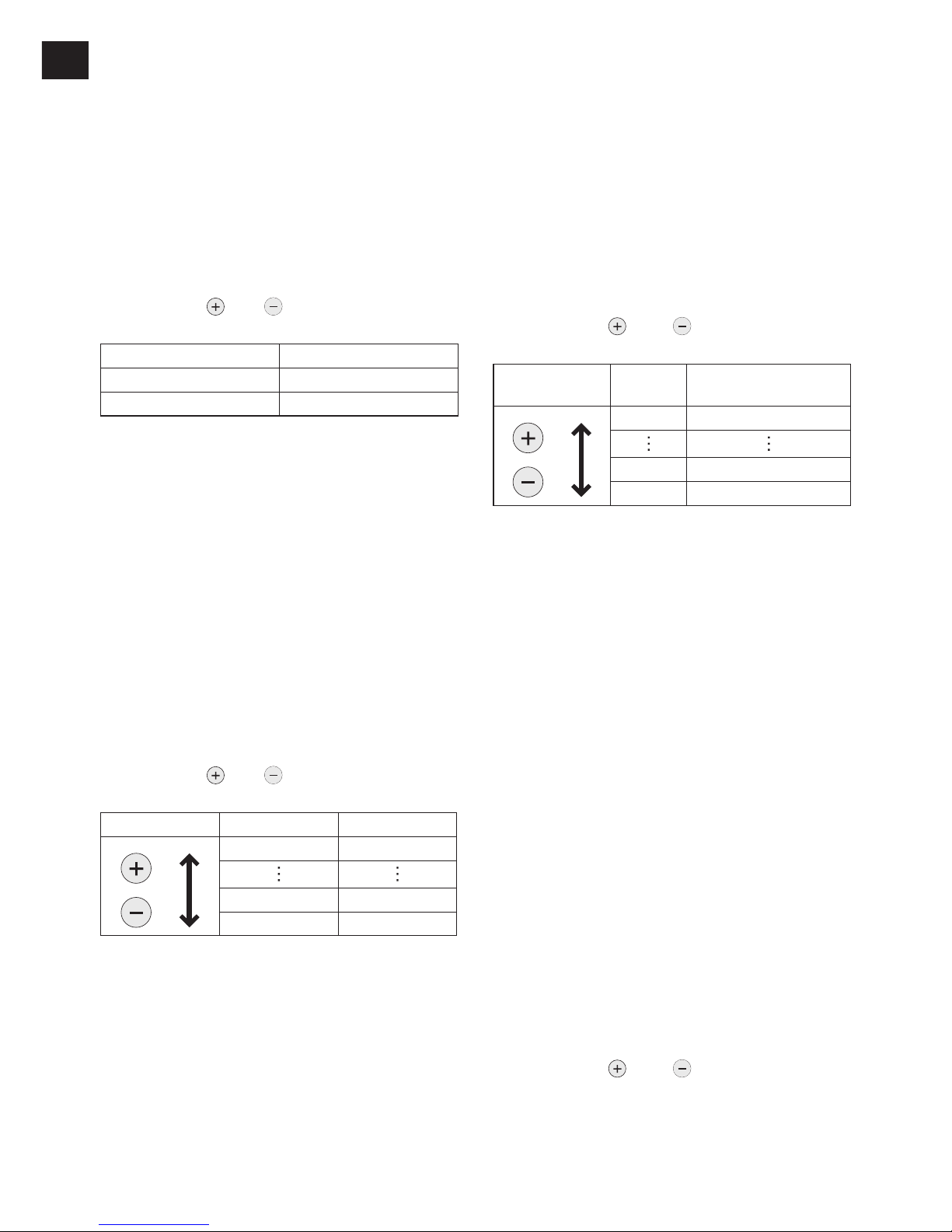
Setting the snug point detection level
[Fig.17]
1. Press the A button.
The snug point detection level setting
value will be displayed.
[Fig.18]
2. Press the
and buttons to set the best
snug point detection level for the work
you’re performing.
3. Press the OK button to accept the number
of torque stages and the snug point detection level.
The tool’s panel will flash and then light up
continuously.
Snug point detection level guidelines
Display
Snug point
detection level
Applications
(reference)
L1
Low
(Use for work
characterized by
low loads before
the snug point is
reached.)
• Tightening bolts in
materials that are
easily cracked or
deformed, etc.
L2
High
(Use for work
characterized
by high loads
before the
snug point is
reached.)
• Tightening bolts
in materials with
misaligned holes,
etc.
• Tightening selftapping screws,
etc.
CAUTION:
Set the snug point detection level from
“L1.” Setting the snug point detection
level from “L2” may result in cracking or
deformation of the target material.
If the tool stops before the snug point at
snug point detection level “L1,” set the
snug point detection level to “L2.”
Changing the snug point detection
level from “L1” to “L2” may increase the
torque. Set the number of torque stages
again after making this change.
The setting will not be changed until
you press the OK button.
After changing the setting, be sure to check
the new setting value. (See page 17.)
IMPORTANT INFORMATION:
You can set the snug point detection
level and retightening prevention time at
the same time by changing the retightening prevention time (See page 15)
before pressing the OK button and then
pressing the OK button.
Pressing the A button toggles the display between the snug point detection
level setting value and the number of
torque stages setting value.
The tool ships with the snug point
detection level set to “L1.”
When the number of torque stages has
been set as shown below, the snug
point detection level cannot be switched
from “L1” to “L2.”
Model
Number of torque stages
setting
EYFPA 1 to 30
EYFNA 1 to 30
•
•
•
•
•
•
•
•
•
-
16 -
EN EN
Cross thread reduction function
The tool runs in reverse approximately 360°
before running forward to assist in the alignment of the threads to help reduce cross
threads.
1. Set the tool to setting configuration mode.
(See page 14.)
2. Press the D button once.
The cross thread reduction function setting
value will be displayed.
3. Press the
and buttons to change the
setting to ON or OFF.
Display Function
R0 OFF
R1 ON
4. Press the OK button to accept the new
setting.
Rundown error detecting function
The rundown error detecting function causes
a red indicator to flash if work ends more
quickly than a set time, for example due to
retightening of a previously tightened fastener
or binding of the screw’s thread.
1. Set the tool to setting configuration mode.
(See page 14.)
2. Press the B button twice.
The rundown error detecting function setting value will be displayed.
3. Press the
and buttons to change the
time as desired.
Operation Display Seconds
30 3 seconds
1 0.1 seconds
0 OFF
4. Press the OK button to accept the new
setting.
When the cross thread reduction function
is ON, the set time will be counted after
the tool operates in reverse for approximately 360°.
Maintenance interval alarm
function
The maintenance interval alarm function locks
the tool so that it can no longer be operated
once a set number of tightening operations
has been performed. This function is convenient when regularly inspecting tool performance, for example.
1. Set the tool to setting configuration mode.
(See page 14.)
2. Press the C button twice.
The setting value will be displayed.
3. Press the
and buttons to set the
desired value.
Operation Display
Number of tightening
operations
99 990,000
1 10,000
0 OFF
4. Press the OK button to accept the new
setting.
NOTE:
When the remaining number of tightening operations is 10,000 or less, the
display will alternate between “Setting”
and “1.” When the remaining number
of tightening operations reaches 0, the
value “0” will flash on the display.
To delay the inspection while retaining
the current tightening operation count
value, select a new setting value that is
greater than the current setting value.
To reset the count to 0, initialize the tool
(see page 17).
The maximum tightening operation
count value is 990,000. Operations in
excess of 990,000 will not be counted.
Buzzer setting
You can select from three buzzer modes.
1. Set the tool to setting configuration mode.
(See page 14.)
2. Press the A button once.
The current setting value will be displayed.
3. Press the
and buttons to set the
desired value.
•
•
-
17 -
Display Function
b0 No buzzer
b1
Buzzer accompanying green indicator
b2 Buzzer accompanying red indicator
4. Press the OK button to accept the new
setting.
NOTE:
The tool ships with the buzzer mode set
to b0 by default.
LED light setting
You can select from two LED light modes.
1. Set the tool to setting configuration mode.
(See page 14.)
2. Press the B button once.
The current setting value will be displayed.
3. Press the
and buttons to set the
desired value.
Display Function
d1 Linked to LED light button
d2
Linked to trigger switch operation
4. Press the OK button to accept the new
setting.
NOTE:
The tool ships with the LED light mode
set to d1 by default.
Speed control function
The speed (RPM) can be changed with the
amount of depression of the trigger.
1. Set the tool to setting configuration mode.
(See page 14.)
2. Press the B button three times.
The setting value will be displayed.
3. Press the
and buttons to set the
desired value.
Operation Function
P0 Speed control ON
P1 Speed control OFF
4.
Press the OK button to accept the new setting.
Initializing all settings
Factory settings
• Torque clutch setting: “F” (torque con
-
trol function off)
• Snug point detection level → L1
• Cross thread reduction function → R0
• Rundown error detecting function → 0
• Maintenance interval alarm function
→ 0
• Radio signal range limitation function
→ C0
• Buzzer setting → b0
• LED light setting → d1
• Speed control setting → P0
• This section explains how to revert all tool
settings to their default values at the time of
shipment from the factory.
• The error display will be turned off.
1. Set the tool to the setting configuration
mode.
(See page 14.)
2. Press the C button.
The control panel will begin flashing.
Display: The letter “F” flashes on and off.
Battery indication lamp: The upper and
lower bars of the battery flash on and off.
[Fig.19]
3. Press the OK button to accept the select
ed setting.
The control panel will stop flashing and
light up.
Checking tool settings
• When the tool stops, the current setting
value will be displayed for approximately 2
seconds.
• The setting status cannot be checked while
the tool panel is off. Depress the trigger
switch once to turn on the panel.

-
18 -
EN EN
Checking the status of the
torque clutch and sung point
detection level setting and
Buzzer settings
Press the A button.
The torque clutch and sung point detection
level setting and buzzer setting values will be
displayed (in that order).
Example: If the torque clutch is set to 30 and
sung point detection level setting L1 and the
buzzer is set to sound at the green indicator,
“30” → “L1” → “b1”
Checking the status of the
LED light and rundown error
detecting function and speed
control function settings
Press the B button.
The LED light and tightening time and speed
control setting will be displayed (in that order).
Example: If the LED light mode is set to L1
and the tightening time is set to 20 and speed
control is set to ON,
“d1” → “20” → P0
Checking the tool circuits and
the status of the cross thread
reduction function settings
Press the D button.
The tool circuits and cross thread reduction
function settings will be displayed (in that
order).
Example: “H3” → “R1”
Display Tool circuit
H1 EYFNA1
H2
EYFPA1
NOTE:
When other tools are in the area which
are not set, they may accidentally
receive a signal when setting the tool
by remote control.
Set the tool in another room if possible
or keep a fair distance to avoid this situation.
-
19 -
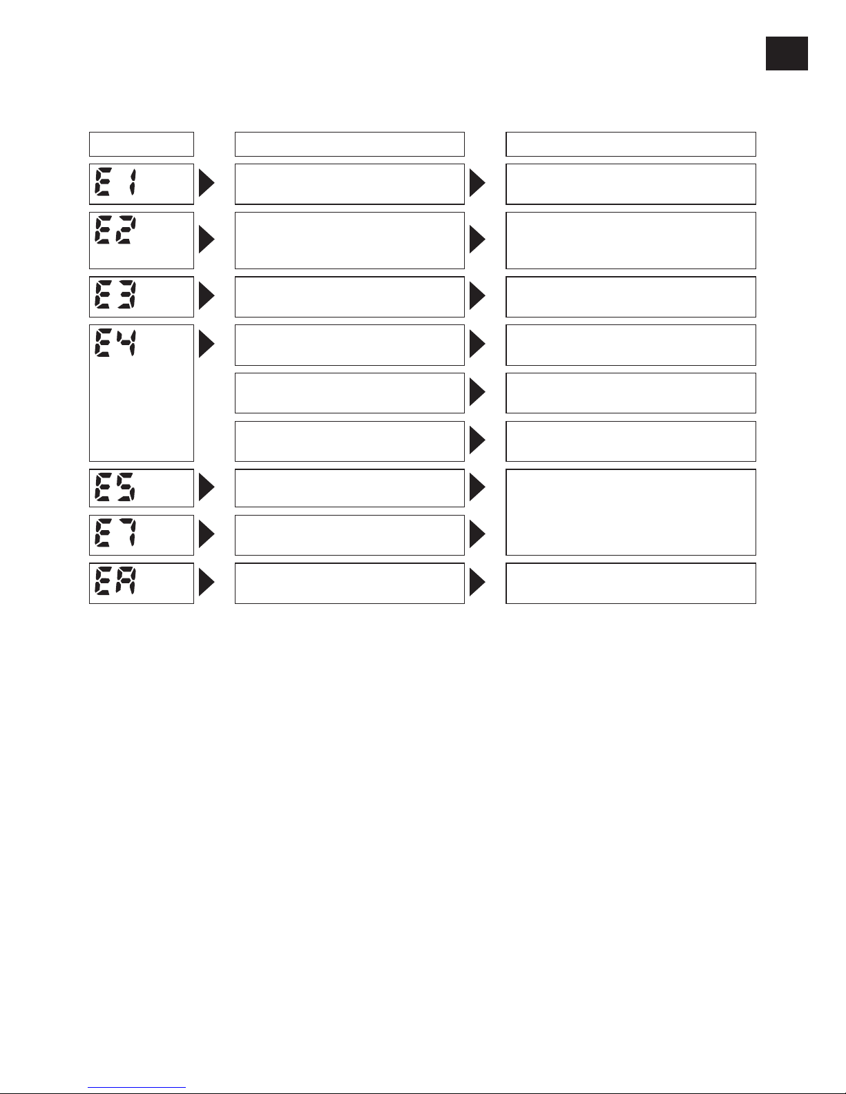
Error Display
In the event of a tool or battery pack malfunction, the control panel will display an error message.
Please check the tool or battery pack as described in the following chart before having them
serviced.
Display Likely cause Corrective action
Setting error Re-initialize the tool using the
remote control. (See page 17.)
The battery pack is too hot. Stop work and allow the battery
pack to cool before resuming use
of the tool.
The tool is too hot to operate. Stop work and allow the tool to
cool before resuming use.
The contacts that connect the
battery pack and tool are dirty.
Remove any dirt.
The battery pack has not been
properly inserted into the tool.
Insert the battery pack rmly into
the tool.
The pins on either the tool or
battery pack have worn down.
Replace the battery pack.
Overload, Motor failure. etc. Stop using the tool immediately.
Tool circuit malfunction, failure,
etc.
The connected battery pack is
not applicable.
Exchange it to an applicable battery pack.
NOTE:
When the tightened bolt is further tightened or loosened, the overload protection function (E5)
may be activated.
-
20 -
EN EN
[Battery Pack]
For Appropriate Use of Bat-
tery Pack
[Fig.20]
•
The rechargeable batteries have a limited
life.
•
For optimum battery life, store the Li-ion battery pack following use without charging it.
•
When operating the battery pack, make sure
the work place is well ventilated.
For safe use
• The battery pack is designed to be installed
by proceeding two steps for safety. Make
sure the battery pack is installed properly to
the main unit before use.
•
If the battery pack is not connected firmly when the switch is switched on, the overheat warning lamp and the battery low warning lamp will flash to indicate that safe operation is not possible, and the main unit will
not rotate normally. Connect the battery
pack into the unit of the tool until the red or
yellow label disappears.
Information for Users on Collection and Disposal of Old Equip
ment and used Batteries
These symbols on the products, packaging, and/or accompanying documents mean
that used electrical and electronic products and batteries should not be mixed with
general household waste.
For proper treatment, recovery and recycling of old products and used batteries, please
take them to applicable collection points, in accordance with your national legislation
and the Directives 2012/19/EC and 2006/66/EC.
By disposing of these products and batteries correctly, you will help to save valuable
resources and prevent any potential negative effects on human health and the
environment which could otherwise arise from inappropriate waste handling.
For more information about collection and recycling of old products and batteries,
please contact your local municipality, your waste disposal service or the point of sale
where you purchased the items.
Penalties may be applicable for incorrect disposal of this waste, in accordance with
national legislation.
[For business users in the European Union]
If you wish to discard electrical and electronic equipment, please contact your dealer or
supplier for further information.
[Information on Disposal in other Countries outside the European
Union]
These symbols are only valid in the European Union. If you wish to discard these items,
please contact your local authorities or dealer and ask for the correct method of disposal.

-
21 -
[Battery Charger]
Charging
Read the operating manual for Panasonic battery charger for the battery pack before charging.
Before charging the battery
Charge the battery at a temperature of 5°C
(41°F) to 40°C (104°F).
The battery pack cannot be charged at a
temperature of less than 5°C (
41°F). If the
temperature of the battery pack is less than
5°C (41°F), rst remove the battery pack from
the charger and allow it to sit for an hour in a
location where the temperature is 5°C (41°F)
or warmer. Then charge the battery pack
again.
V.
MAINTENANCE
Use only a dry, soft cloth for wiping the unit.
Do not use a damp cloth, thinner, benzine,
or other volatile solvents for cleaning.
Regular greasing is recommended.
Contact your nearest dealer or service center.
•
•
VI
. ACCESSORIES
Charger
EY0L82
Battery pack for EYFPA1
EYFB60
Battery pack for EYFNA1
EYFB50
Remote control
EYFA31
Protector for tool EYFPA1
• EYFA07-A (Blue)
• EYFA07-Y (Yellow)
• EYFA07-H (Gray)
• EYFA07-G (Green)
Protector for tool EYFNA1
• EYFA09-A (Blue)
• EYFA09-Y (Yellow)
• EYFA09-H (Gray)
• EYFA09-G (Green)
Protector for battery EYFB60
EYFA08-H
Protector for battery EYFB50
EYFA10-H
Tool hanger
EYFA41
CAUTION:
Tool hanger is for balancer use only.
Excessive force or impact might break it
and the main unit might fall off.
Use only applicable battery pack;
EYFB60 for EYFPA1
EYFB50 for EYFNA1
•
•
-
22 -
EN EN
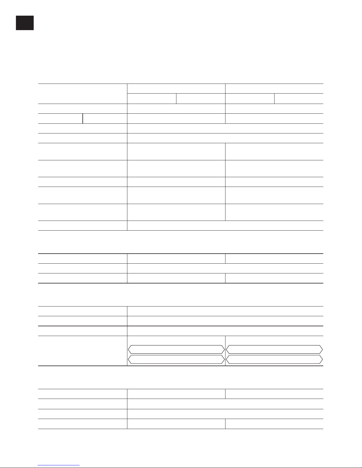
VII
. SPECIFICATIONS
NOTE:
Weight indication
Greater than or equal to 1 kg : indicated by 0.05 kg.
Less than 1 kg : indicated by 0.01 kg.
MAIN UNIT
Model No.
EYFPA1 EYFNA1
C J C J
Motor voltage 21.6 V DC 18 V DC
Chuck size Single-ended □19.0 mm □12.7 mm
No load speed 0 – 1900
Impact per minute 0 – 2200
Maximum torque
700 N·m
(7140 kgf·cm)
470 N·m
(4790 kgf·cm)
Torque control function
operating range
Approx. 160 – 650 N·m
(1630 – 6630 kgf·cm)
Approx. 70 – 200 N·m
(710 – 2040 kgf·cm)
Overall length 250 mm 233 mm
Weight (with battery pack:
EYFB60)
3.6 kg –
Weight (with battery pack:
EYFB50)
– 3.0 kg
Noise, Vibration See the included sheet
BATTERY PACK (not included with shipment)
Model No. EYFB60 EYFB50
Storage battery Li-ion battery
Battery voltage 21.6 V DC (3.6 V/6 cells) 18 V DC (3.6 V/10 cells)
BATTERY CHARGER (not included with shipment)
Model No. EY0L82
Rating See the rating plate on the bottom of the charger.
Weight 0.93 kg
Charging time EYFB60
Usable: 65 min.
Full: 85 min.
EYFB50
Usable: 65 min.
Full: 80 min.
Remote control (not included with shipment)
Model EYFA30 EYFA31
Battery voltage 3 V DC
Dimensions 54 mm × 86 mm × 10 mm
Weight (with battery) Approximately 29 g Approximately 30 g
-
23 -
ONLY FOR U. K.
VIII
.
ELECTRICAL PLUG
INFORMATION
FOR YOUR SAFETY PLEASE READ
THE FOLLOWING TEXT CAREFULLY
This appliance is supplied with a moulded
three pin mains plug for your safety and
convenience.
A 5 amp fuse is tted in this plug.
Should the fuse need to be replaced please
ensure that the replacement fuse has a rating of 5 amp and that it is approved by ASTA
or BSI to BS1362.
Check for the ASTA mark or the BSI mark
on the body of the fuse.
If the plug contains a removable fuse cover
you must ensure that it is retted when the
fuse is replaced.
If you lose the fuse cover the plug must not
be used until a replacement cover is obtained.
A replacement fuse cover can be purchased
from your local Panasonic Dealer.
IF THE FITTED MOULDED PLUG IS UNSUITABLE FOR THE SOCKET OUTLET IN
YOUR HOME THEN THE FUSE SHOULD
BE REMOVED AND THE PLUG CUT OFF
AND DISPOSED OF SAFELY.
THERE IS A DANGER OF SEVERE ELECTRICAL SHOCK IF THE CUT OFF PLUG
IS INSERTED INTO ANY 13 AMP SOCKET.
If a new plug is to be tted please observe
the wiring code as shown below.
If in any doubt please consult a qualied
electrician.
IMPORTANT:
The wires in this mains lead are
coloured in accordance with the following code:
Blue: Neutral
Brown: Live
As the colours of the wire in the mains lead
of this appliance may not correspond with
the coloured markings identifying the terminals in your plug, proceed as follows.
The wire which is coloured BLUE must be
connected to the terminal in the plug which
is marked with the letter N or coloured
BLACK.
The wire which is coloured BROWN must be
connected to the terminal in the plug which is
marked with the letter L or coloured RED.
Under no circumstances should either of
these wires be connected to the earth terminal of the three pin plug, marked with the
letter E or the Earth Symbol .
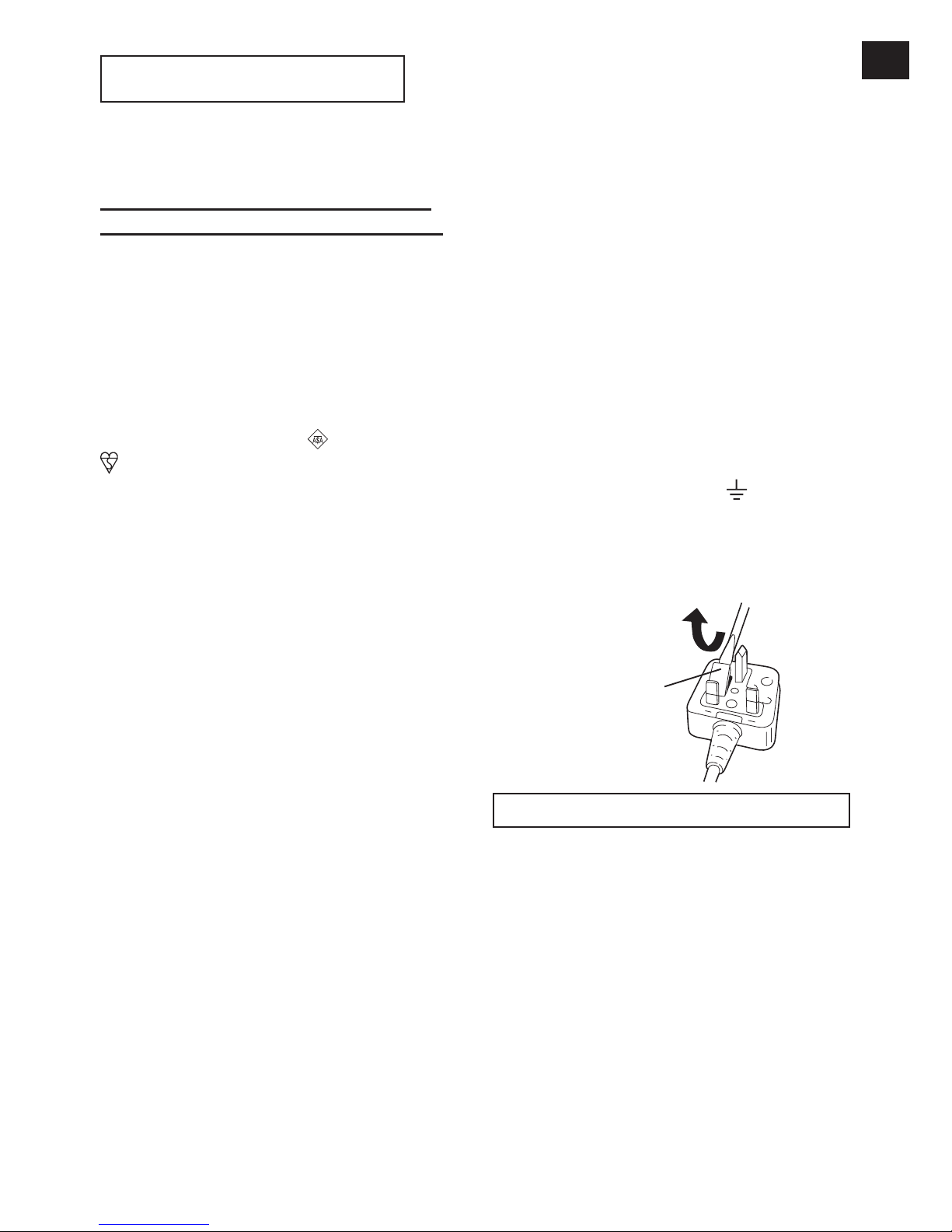
How to replace the fuse: Open the fuse
compartment with a screwdriver and replace
the fuse and fuse cover if it is removable.
Fuse Cover
This apparatus was produced to BS800.

-
24 -
DE DE
Original-Anleitung: Englisch
Übersetzung der Original-Anleitung:
Andere Sprachen
I
. VERWENDUNGS
ZWECK
Dieses Werkzeug ist ein Akku-Schlagschrauber und kann zum Anziehen von Bolzen,
Muttern und Schrauben verwendet werden.
Darüber hinaus bietet es eine AnzugsmomentSteuerfunktion, die den Werkzeugbetrieb au
tomatisch stoppt, wenn eine voreingestellte
Last erreicht wird, um ein gleichmäßiges Anzugsmoment zu liefern.
FALSCHER GEBRAUCH
ZWECKENTFREMDETER GEBRAUCH des
Werkzeugs ist gefährlich und muss vermieden
werden.
Das Werkzeug darf nicht für folgende Zwecke
verwendet werden:
• Mischen von Lackfarben oder Baumaterial,
• Polieren, Schleifen, Schärfen, Gravieren.
RESTRISIKO
Einige Restrisiken wie die folgenden bleiben
selbst bei sachgemäßem Gebrauch des Werkzeugs bestehen:
• Kontakt mit dem rotierenden Einsatz
• Kontakt mit scharfen Kanten des Materials
oder dergleichen.
Lesen Sie bitte vor der ersten
Inbetriebnahme dieses Gerätes das se
parate Handbuch „Sicherheitsmaßregeln“ sorgfältig durch.
II
.
WEITERE WICHTIGE
SICHERHEITSREGELN
1) Falls das Bit stecken bleibt, lassen Sie
sofort den Elektronikschalter los, um eine
Überlastung zu verhüten, die den Akku
oder Motor beschädigen kann. Verwenden Sie die Rückwärtsdrehung, um klemmende Bits zu lösen.
2) Betätigen Sie den Rechts-/Linkslauf-
Umschalthebel NICHT, wenn der Hauptschalter eingeschaltet ist. Der Akku entlädt sich sonst schnell, und das Gerät
kann beschädigt werden.
3) Beim Aufladen kann sich das Lade-gerät
etwas erhitzen. Dies ist normal. Den Akku
daher NICHT über lange Zeit aufladen.
4) Belasten Sie das Werkzeug nicht, indem
Sie den Elektronikschalter halb gedrückt
halten (Drehzahlregelmodus), sodass der
Motor stehen bleibt.
5) Um Verletzungen während des Gebrauchs
zu vermeiden, halten Sie das Werkzeug
immer fest und vermeiden, es herumzuschwenken.
6) Stellen Sie sicher, dass keine versteck
ten Gas- oder Wasserrohre und auch
keine elektrischen Leitungen im beabsichtigten Arbeitsbereich vorhanden sind. Ein
unbeabsichtigter Kontakt mit versteckten
Rohren oder Leitungen kann zu Stromschlägen oder Wasser- bzw. Gaslecks
führen.
7) Achten Sie darauf, den Gegenstand, an
dem Sie arbeiten, richtig festzuhalten.
8) Prüfen Sie, ob beschädigte Teile vorhan
-
den sind.
• Prüfen Sie vor der Inbetriebnahme
Schutzabdeckung und andere Teile
gründlich auf Schäden.
• Stellen Sie sicher, dass das Werkzeug
und alle seine Funktionen korrekt arbeiten.
• Kontrollieren Sie die Anpassung aller
beweglichen Teile, und überprüfen Sie
alle festen Teile, um sicherzustellen,
dass sie richtig eingebaut wurden und
frei von Schäden sind. Überprüfen Sie
alle Teile des Werkzeugs auf einwandfreie Funktionstüchtigkeit.
9) Wenn Sie versuchen, die Schutzabde
ckung oder andere Teile zu reparieren,
befolgen Sie bitte die Anweisungen im
Benutzerhandbuch. In Fällen, wo es keine
Anleitungen im Handbuch gibt, bringen
Sie das Gerät zurück in den Laden, um
es dort reparieren zu lassen.
10) Wenn d as Werkzeug währ end des
Gebrauchs außergewöhnlich heiß wird,
bringen Sie es bitte zurück zum Fachhändler, um es dort warten und reparieren
zu lassen.
11) Um mögliche Verletzungen zu vermeiden,
halten Sie Gesicht und Hände von Bohrer
und Spänen entfernt.
12) Tragen Sie keine Handschuhe beim
Gebrauch des Werkzeugs, da diese in
den Bohrer gelangen und Verletzungen
verursachen können.
13) Batterieanschlüsse, Schraubenspäne und
Werkzeugzubehör wie Bohreinsätze sind
unmittelbar nach dem Betrieb sehr heiß.
Berühren Sie diese nicht, da die Gefahr
von Verbrennungen besteht.
-
25 -
WARNUNG:
Verwenden Sie nur die Panasonic-Akkus,
die für den Einsatz mit dieser AkkuMaschine ausgelegt sind.
Panasonic übernimmt keine Verantwortung für etwaige Schäden oder Unfälle, die
durch den Gebrauch von recycelten oder
gefälschten Akkus verursacht werden.
Werfen Sie den Akku nicht ins Feuer, und
setzen Sie ihn auch keiner übermäßigen
Wärme aus.
Achten Sie darauf , dass keine Metallgegenstände mit den Kontakten des Akkus
in Berührung kommen.
Unterlassen Sie das Tragen oder Aufbewahren des Akkus zusammen mit Nägeln
oder ähnlichen Metallgegenständen im
selben Behälter.
Laden Sie den Akku nicht an einem heißen Ort, wie z. B. in der Nähe eines Feuers oder in direktem Sonnenlicht. Anderenfalls kann der Akku überhitzen, Feuer
fangen oder explodieren.
Nachdem Sie den Akku von der Maschine
oder dem Ladegerät abgenommen haben,
bringen Sie stets die Akkuabdeckung wieder an. Anderenfalls könnten die Akkukontakte kurzgeschlossen werden, was
zu einem Brand führen kann.
Wenn der Akku schwach geworden ist,
ersetzen Sie ihn durch einen neuen. Fortgesetzter Gebrauch eines beschädigten
Akkus kann zu Wärmeerzeugung, Entzündung oder Bruch führen.
Um Leckagen, Überhitzung, Rauchentwicklung, Brände und Explosionen zu verhindern, befolgen Sie beim Umgang mit
unseren Akku-Elektrowerkzeugen (Hauptteil/Akku/Ladegerät) diese Anweisungen.
Lassen Sie kein Bohrklein oder Staub
auf den Akku fallen.
Bevor Sie den Akku wieder verstauen,
entfernen Sie das gesamte Bohrklein
und den Staub von ihm. Lagern Sie den
Akku getrennt von Metallgegenständen
(Schrauben, Nägeln usw.) im Werkzeugkoffer.
Behandeln Sie die Akku-Elektrowerkzeuge keinesfalls wie folgt:
(Es besteht die Gefahr von Rauchentwicklung, Feuer und Explosion.)
Verwenden oder Liegenlassen in Bereichen, die Regen oder Feuchtigkeit ausgesetzt sind
Verwendung unter Wasser
•
•
•
•
•
•
•
•
•
-
-
•
-
-
Symbol Bedeutung
V
Volt
Gleichstrom
n
0
Drehzahl ohne Last
… min
-1
Drehzahl oder Hubzahl pro
Minute
Ah
Akkukapazität in Amperestun-
den
Um die Verletzungsgefahr
zu verringern, muss
jeder Benutzer die
Gebrauchsanleitung lesen und
verstehen.
Unterlassen Sie Verbrennen
oder Erhitzen des Akkus.
Unterlassen Sie Laden oder
Benutzen des Akkus bei hohen
Temperaturen. Nicht hohen
Temperaturen aussetzen.
Nicht zerlegen oder abändern.
Nicht Regen oder Wasser
aussetzen.
III
. BAUGRUPPE
VORSICHT:
Vergewissern Sie sich, dass die
Stecknuss, die Verlängerung oder ein
anderer Aufsatz, der zum Halten von
Befestigungselementen mit dem Werkzeug verwendet wird, speziell für Elektrowerkzeuge (Schlagschrauber) ausgelegt ist.
Wird das Werkzeug mit Aufsätzen verwendet, die für Handwerkzeuge ausgelegt sind, können die Aufsätze brechen
und mögliche Gefahren verursachen.
Vergewissern Sie sich außerdem vor
der Arbeit, dass der Aufsatz einwandfrei
ist.
HINWEIS:
Falls eine verschlissene oder verformte
Stecknuss verwendet wird, passt der
Antriebsvierkant (Haltering und Stift) u.
U. nicht richtig in die Stecknuss.
-
26 -
DE DE
Anbringen einer Stecknuss
(Stifttyp)
Den Gummiring und Stift der Stecknuss entfernen.
[Fig.1]
1 Die Stecknuss am Werkzeug anbringen.
2 Den Stift einsetzen. (Die Stiftlöcher in
Stecknuss und Werkzeug sorgfältig aus
-
richten.)
3 Den Gummiring durch Aufschieben auf die
Nut anbringen.
[Fig.2]
HINWEIS:
Bringen Sie unbedingt den Gummiring
an, um Herausfallen des Stifts zu verhüten.
Abnehmen einer Stecknuss
(Stifttyp)
1 Den Gummiring entfernen.
2 Den Stift entfernen.
3 Die Stecknuss vom Werkzeug abnehmen.
[Fig.3]
HINWEIS:
Halten Sie die Temperatur des Werkzeugs über dem Gefrierpunkt (0°C),
wenn Sie Stecknüsse am Vierkant
des Werkzeugs anbringen oder davon
abnehmen. Wenden Sie beim Anbringen oder Abnehmen von Stecknüssen
keine übermäßige Kraft an.
Anbringen oder Abnehmen
des Akkus
1. Zum Anschließen des Akkus:
Die Ausrichtmarkierungen aufeinander
ausrichten, und den Akku anbringen.
Den Akku einschieben, bis er einrastet.
[Fig.4]
2. Zum Entfernen des Akkus:
Den Knopf nach unten drücken, und den
Akku nach vorn schieben.
[Fig.5]
Anbringen des Werkzeugaufhängers
1. Lösen Sie den Stift und den Clip vom
Werkzeugaufhänger.
[Fig.6]
2. Richten Sie die Löcher im Werkzeugauf
hänger auf die Löcher im Werkzeuggehäuse aus.
[Fig.7]
3. Stecken Sie den Stift in die Löcher im
Werkzeugaufhänger und im Werkzeuggehäuse.
Hängen Sie den Clip in die Löcher des
Werkzeugaufhängers ein.
[Fig.8]
IV
. BETRIEB
WARNUNG!
Atmen Sie nicht den vom Werkzeug oder
vom Akkupack ausströmenden Rauch ein,
da er gesundheitsschädlich sein kann.
Vergleichstabelle für Fernbedienung
EYFA31 / EYFA30
EYFA31 EYFA30
Taste D (P)
Anzugsmomentstufentaste
(V)
Taste C (Q) Formattaste (W)
Taste B (R) Intervall-Einstelltaste (X)
Taste A (S)
Anzugsmoment-Einstelltaste
(Y)
Diese Bedienungsanleitung wurde mit
dem Inhalt des Modells EYFA31 verfasst.
Bei Verwendung mit EYFA30 nehmen
Sie auf das obige Diagramm Bezug, und
ersetzen Sie EYFA30 durch EYFA31.
Vor Benutzung der Fernbedienung (Als Sonderzubehör erhältlich)
[Fig.9]
Die Batterie einlegen
1. Den Batteriehalter herausziehen.
1 Die Raste in Pfeilrichtung hineindrücken.
2 Den Halter herausziehen.

-
27 -
2. Die Batterie einlegen, und den Halter wieder einschieben.
HINWEIS:
Falls das Werkzeug nicht auf die drahtlose Fernbedienung reagiert, selbst
wenn die Fernbedienung nahe am
Werkzeug betätigt wird, ist die Batterie
(CR2025) erschöpft. Ersetzen Sie die
Batterie durch eine neue.
Die mitgelieferte Batterie ist für Probebetrieb vorgesehen und hält möglicherweise nicht so lange wie eine im Handel
erhältliche Batterie.
Reichweite der drahtlosen Fernbedienung
[Fig.10]
Die Fernbedienung sollte innerhalb von etwa
50 cm und 60° vertikal und horizontal zur
Senkrechten relativ zum Infrarotempfänger
des Werkzeugs betätigt werden.
• Unter den folgenden Umständen lässt sich
das Werkzeug selbst innerhalb dieses
Bereichs eventuell nicht bedienen.
- Wenn sich ein Gegenstand zwischen dem
Geber der Fernbedienung und dem Empfänger des Werkzeugs befindet.
- Bei Verwendung im Freien oder in ande
ren Umgebungen, wo der Fernbedienungsempfänger einer starken Lichtquelle
ausgesetzt ist, oder wenn der Fernbedienungsgeber oder -empfänger schmutzig
ist, reagiert das Werkzeug eventuell nicht,
selbst wenn die Fernbedienung innerhalb
des Wirkungsbereichs benutzt wird.
[Hauptgerät]
VORSICHT:
Falls Sie einen Werkzeughalter mit
den Montagewerkzeugen der Panasonic EYF-Serie benutzen, vergewissern
Sie sich, dass der Elektronikschalter
des Werkzeugs nicht gegen den Werkzeughalter stößt. Anderenfalls kann das
Werkzeug versehentlich eingeschaltet
werden, was zu Akkuausfall durch unerwartete Entladung führt.
[Fig.11]
VORSICHT:
Stellen Sie den Rechts-/LinkslaufUmschalthebel zum Lagern oder Tragen des Werkzeugs auf die Mittenstellung (Schaltersperre).
•
•
HINWEIS:
Seien Sie vorsichtig, um zu vermeiden, dass Gegenstände mit dem Auslöseschalter des Werkzeugs in Berührung kommen. Falls ein Gegenstand
in Berührung mit dem Auslöseschalter des Werkzeugs kommt, auch wenn
der Rechts-/Linkslauf-Schalter in der
Mittelstellung (gesperrt) steht, kann
möglicherweise eine kleine Menge des
elektrischen Stroms weiter fließen. Dies
kann zu einer übermäßigen Entladung
des Akkus und dadurch zum Ausfall
des Akkus führen.
Umschalten und Betätigung
des Rechts/Linkslauf Ums
chalthebels
[Fig.12]
1. Für Rechts- oder Linkslauf den Hebel drü
cken. Die Drehrichtung des Hebels vor
dem Betrieb prüfen.
2. Drücken Sie den Schalter leicht, um das
Werkzeug langsam zu starten.
3. Durch Drücken des Auslösers erhöht sich
die Geschwindigkeit. Wird der Auslöser
losgelassen, stellt das Werkzeug sofort
den Betrieb ein.
4. Wenn eine Anwendung beendet wurde,
verriegeln Sie den Schalter, indem Sie den
Hebel auf die Mittelstellung stellen.
HINWEIS:
Je weiter der Elektronikschalter hineingedrückt wird, desto höher wird die
Drehzahl.
VORSICHT:
Wird die Maschine durch Betätigen des
Auslösers gestartet, kann eine kurzzeitige Verzögerung auftreten, bevor die
Drehung beginnt. Dies ist kein Anzeichen für eine Funktionsstörung.
* Diese Verzögerung tritt beim Hoch
fahren der Schaltkreise der Maschine auf, wenn der Auslöser zum ersten Mal nach dem Einsetzen eines
Akkus betätigt wird, oder nachdem die
Maschine mindestens 1 Minute lang
nicht benutzt worden ist (oder mindestens 5 Minuten bei leuchtender LED).
Bei der zweiten und jeder weiteren
Betätigung läuft die Maschine ohne
Verzögerung an.

-
28 -
DE DE
Anzugsbestätigungslampe
Anhand der Anzugsbestätigungslampe kann
festgestellt werden, ob die AnzugsmomentSteuerfunktion aktiviert wurde.
Werkzeugstatus Lampenanzeige
Anziehen beendet
(bei wirksamer
AnzugsmomentSteuerfunktion)
Grün
(Für ca. 2
Sekunden)
• Anziehen unvollständig
• Anziehen beendet mit
Nachziehen innerhalb 1
Sekunde
Rot
(Für ca. 2
Sekunden)
Die automatische
Stoppfunktion ist aktiviert
worden.
Rot
(Für ca. 5
Minuten)
VORSICHT:
Wenn das Werkzeug automatisch
anhält, nachdem der Schalter während
des Anziehens im Schlagmodus losgelassen wurde und dann innerhalb 1
Sekunde wieder betätigt wird, leuchtet
die rote Lampe auf, um auf die Gefahr
eines übermäßigen Anzugsmoments
durch Nachziehen hinzuweisen.
HINWEIS:
Unter den folgenden Bedingungen
leuchtet die Anzugsbestätigungslampe
nicht auf:
Wenn die Drehmomentkupplung auf „F“
gesetzt wird
Während des Linkslaufbetriebs
Die Lampe erlischt, wenn das Werkzeug in Betrieb ist.
Bedienfeld
[Fig.13]
(1) AnzugsmomentSteuerfunktion
Die Anzugsmoment-Steuerfunktion berechnet die Last anhand des Motordrehwinkels
während des Hammerschlags und stellt fest,
dass die Schraube einwandfrei aufsitzt, wenn
ein voreingestellter Lastwert überschritten
wird. Der Anziehvorgang wird dann automatisch gestoppt, nachdem eine voreingestellte
Anzahl von Schlägen auf die Schraube ausgeübt worden ist.
VORSICHT:
Überprüfen Sie stets das Anzugsmoment des Werkzeugs vor Gebrauch.
•
•
•
•
•
Die erforderliche Einstellung hängt von
der Art der Gewindeverbindung ab und
kann am besten durch praktische Versuche ermittelt werden. Überprüfen Sie
die Probeverschraubungen mit einem
Drehmomentschlüssel. Falscher Werkzeugbetrieb kann zu übermäßigem oder
unangemessenem Anziehen führen.
Betreiben Sie das Werkzeug stets mit
voll eingerücktem Schalter. Die Anzugsmoment-Steuerfunktion ist unwirksam,
wenn der Schalter nicht richtig eingerastet ist, so dass automatisches Stop
pen des Werkzeugs verhindert wird.
Wenn Arbeiten ausgeführt werden, bei
denen während des Anziehens eine
große Kraft ausgeübt wird, kann die
Kraft als Aufsitzen der Schraube interpretiert werden, wodurch vollständiges
Anziehen der Schraube verhindert wird.
Durch wiederholtes Anziehen derselben
Schraube kann infolge übermäßigen
Anziehens die Schraube beschädigt
oder das Material, in das die Schraube
eingedreht wird, verformt werden.
Der Anzugsmomentwert und die Genauigkeit hängen von solchen Faktoren
wie dem Material, in das die Schraube
eingedreht wird, und dem Zustand der
verwendeten Stecknuss ab. Passen
Sie das Anzugsmoment je nach Bedarf
an die durchgeführte Arbeit an. Das
Schrauben-Anzugsmoment hängt von
den unten beschriebenen Faktoren ab.
1) Schraube
•
Schraubendurchmesser: Das Anzugsmoment nimmt im Allgemeinen mit
dem Schraubendurchmesser zu.
• D re hmo me ntk oe ff izi en t ( vom
Schraubenhersteller angegeben),
Grad, Länge usw.
2) Sonstiges
•
Zustand von Einsatz und Stecknuss: Material, Spielbetrag usw.
• Verwendung eines Kreuzgelenks
oder Steckschlüsseladapters
• Benutzer: Art und Weise des
Ansetzens des Werkzeugs an
die Schraube, Kraft, mit der das
Werkzeug gehalten wird, Art und
Weise der Betätigung des Werkzeugschalters
• Zustand des zu verschraubenden
Objekts: Material, Verarbeitung der
Sitzfläche
•
•
•
•
-
29 -
(2) AkkuAnzeigelampe
• Anhand der Akku-Anzeigelampe können Sie
den Ladezustand des Akkus feststellen.
• Die Nutzungsdauer des Akkus unterlie
gt je nach der Umgebungstemperatur und
den Akku-Eigenschaften geringen Schwankungen. Die Lampe dient dazu, eine ungefähre Anzeige der Restnutzungsdauer des
Akkus zu liefern.
Anzeige Akkustatus
Voll aufgeladen
ca. 40% oder weniger
Restladung
Blinken
Blinken
ca. 20 % oder weniger
Restladung (Akku muss
aufgeladen werden)
Der Akku muss bald aufgeladen werden.
Blinken
Keine Ladung
Der Akku muss aufgeladen
werden.
(In diesem Stadium wird
die Abschaltautomatik des
Werkzeugs aktiviert.)
Abschaltautomatik
Die Abschaltautomatik dient dazu, ein mangelhaftes Anzugsmoment durch reduzierte Akkuspannung zu verhüten. Wenn die Funktion einmal aktiviert worden ist, lässt sich das Werkzeug nicht benutzen, bis der Akku aufgeladen
(oder durch einen frischen ersetzt) worden ist,
selbst wenn der Auslöser gedrückt wird.
HINWEIS:
Alle 3 Balken der Akku-Anzeigelampe
blinken, wenn die Abschaltautomatik
aktiviert wird.
Wenn die Akku-Anzeigelampe zu blinken beginnt, sollte der Akku unverzüglich aufgeladen (oder durch einen frischen ersetzt) werden.
Laden Sie den betreffenden Akku
nach der Aktivierung der Abschaltautomatik voll auf. Anderenfalls wird die
Abschaltautomatik eventuell nicht kor
-
rekt deaktiviert.
•
•
•
(3) LED-Leuchte
Diese Funktion ist auf „Mit LED-Leuchten-Taste gekoppelt“ begrenzt.
[Fig.14]
Durch Drücken von wird die LED-Leuchte
ein- und ausgeschaltet.
Die Leuchte verbraucht nur sehr wenig Strom
und beeinträchtigt weder die Leistung des
Werkzeugs während des Betriebs noch die
Akkukapazität.
VORSICHT:
Die eingebaute LED-Leuchte ist für
kurzzeitige Beleuchtung eines kleinen
Arbeitsbereichs ausgelegt.
Verwenden Sie sie nicht als Ersatz für
eine normale Taschenlampe, weil sie
nicht hell genug ist.
Vorsicht: SEHEN SIE NICHT IN DEN
STRAHL.
Die Verwendung von Bedienelementen, Einstellungen oder Vorgängen außer den hier beschriebenen kann zur Freisetzung gefährlicher
Strahlung führen.
Einstellen des Werkzeugs auf
den Konfigurationsmodus
1. Das Bedienfeld ausschalten.
Falls das Bedienfeld eingeschaltet ist, den
Akku entnehmen und wieder einsetzen.
2. Den Schalter einrücken, während die
Taste gedrückt wird, und dann die
Taste und den Schalter loslassen.
Nachdem alle LED-Lampen erloschen
sind, blinkt das Bedienfeld und wechselt
zum Konfigurationsmodus.
[Fig.15]
HINWEIS:
Das Werkzeug wurde werksseitig auf
den Modus „F“ (Anzugsmoment-Steuerfunktion abgeschaltet) eingestellt.
Das Bedienfeld schaltet sich aus, wenn
das Werkzeug für die Dauer von 5
Minuten nicht benutzt wird.
Konfigurieren der Drehmomentkupplungs-Einstellung
[Fig.16]
•
•
•
•
-
30 -
DE DE
1. Wählen Sie durch Drücken der Tasten
und die für die durchzuführende Arbeit
geeignete Kupplungseinstellung.
3…28
1F30 229
Drücken der
Taste
Drücken der
Taste
• „F“ zeigt an, dass die AnzugsmomentSteuerfunktion abgeschaltet ist.
• 30 Einstellungen der Drehmomentkupplung (1 bis 30) stehen zur Auswahl.
• Treffen Sie Ihre Wahl der Drehmomentkupplungs-Einstellung anhand der Werte
im Anzugsmomentdiagramm. (Siehe
das nachstehende Anzugsmomentdiagramm)
2. Drücken Sie die Taste OK, um die gewähl
te Drehmomentkupplungs-Einstellung zu
akzeptieren.
Das Bedienfeld hört auf zu blinken und
leuchtet auf.
VORSICHT:
• Sie müssen die Taste OK drücken,
damit die gewählte Einstellung wirksam
wird.
• Bestätigen Sie den neuen Wert nach
einer Änderung der Einstellung.
Anzugsmomentdiagramm (nur
für Referenzzwecke)
Die in diesem Diagramm angegebenen Werte wurden unter den nachfolgend beschriebenen Bedingungen gemessen und dienen
Referenzzwecken. Das tatsächliche Anzugsmoment schwankt je nach den Umgebungsbedingungen (anzuziehende Schraube,
verwendete Hardware, Haltemethode der
Schraube usw.).
700 (7140)
600 (6120)
500 (5100)
400 (4080)
300 (3060)
200 (2040)
100 (1020)
0
N·m (kgf·cm)
11 5 10 15 20 25 30
M24
M20
M18
M16
Drehmoment-Einstellungsstufe
Anzugsmoment
EYFPA1C, EYFPA1J
300 (3060)
250 (2550)
200 (2040)
150 (1530)
100 (1020)
50 (510)
0
N·m (kgf·cm)
11 5 10 15 20 25 30
M18
M16
M14
M12
Anzugsmoment
Drehmoment-Einstellungsstufe
EYFNA1C, EYFNA1J
Einstellen des AufsitzpunktErkennungsniveaus
[Fig.17]
1. Drücken Sie die Taste A.
Der Einstellwert des Aufsitzpunkt-Erkennungsniveaus wird angezeigt.
[Fig.18]
2.
Drücken Sie die Tasten und , um das
optimale Aufsitzpunkt-Erkennungsniveau
für die durchzuführende Arbeit einzustellen.
3. Drücken Sie die Taste OK, um die Zahl
der Drehmomentstufen und das Aufsitzpunkt-Erkennungsniveau zu akzeptieren.
Das Bedienfeld des Werkzeugs blinkt und
leuchtet dann ständig.
Richtlinien für Aufsitzpunkt-Erkennungsniveau
Anzei-
ge
Aufsitzpunkt-Er-
kennungsniveau
Anwendungen
(Referenz)
L1
Niedrig
(Für Arbeiten
verwenden,
die durch nied-
rige Lasten
charakterisiert
werden, bevor
der Aufsitzpunkt
erreicht wird.)
• Anziehen von
Schrauben in
Material, das
anfällig für Rissbildung oder Verformung usw. ist.
L2
Hoch
(Für Arbeiten
verwenden,
die durch
hohe Lasten
charakterisiert
werden, bevor
der Aufsitzpunkt
erreicht wird.)
• Anziehen von
Schrauben in
Material mit
falsch ausgerichteten Löchern
usw.
• Anziehen von
Schneidschrauben
usw.
 Loading...