

Page 1
Operating Instructions
Bedienungsanleitung
Instructions d’utilisation
Istruzioni per l’uso
Gebruiksaanwijzing
Manual de instrucciones
Brugsvejledning
Driftsföreskrifter
Bruksanvisning
Käyttöohjeet
Инструкция по эксплуатации
Iнструкцiя з експлуатації
Návod k obsluze
Model No: EYFLA1A / EYFLA2A
Cordless Impact Driver/Cordless Impact Wrench
Akku-Schlagschrauber
Perceuse à impact sans l/Clé de serrage à impact sans l
Avvitatore ad impulsi senza li/Chiave ad impulsi senza li
Snoerloze slagschroevendraaier/Snoerloze slagmoersleutel
Destornillador de impacto inalámbrico/Llave de impacto inalámbrica
Akku-slagboremaskine/Akku-slagnøgle
Sladdlös slagskruvdragare/Sladdlös slagskruvnyckel
Trådløs slagbormaskin/Trådløs slagnøkkel
Langaton iskuruuviavain/Langaton iskuavain
Ударный аккумуляторный шуруповерт/Ударный аккумуляторный гайковерт
Ударний акумуляторний шуруповерт/Ударний акумуляторний гайковерт
Bezdrátový elektrický utahovák / Bezdrátový nárazový šroubovák
EYFLA2Q / EYFLA3J
* Pictured: Cordless impact driver
* Abgebildet: Akku-Schlagschrauber
* Image: Perceuse à impact sans l
* Nell’immagine: Avvitatore ad impulsi senza li
* Afgebeeld: Snoerloze slagschroevendraaier
* En la imagen: Destornillador de impacto inalámbrico
* Billedet viser: Akku-slagskruetrækker
* På bild: Sladdlös slagskruvdragare
* Avbildet: Trådløs slagdriver
* Kuvassa: Langaton iskuavain
* На рисунке: Ударный аккумуляторный шуруповерт
* На малюнку: Ударний акумуляторний шуруповерт
* Zobrazení: Bezdrátový elektrický utahovák
Before operating this unit, please read these instructions completely and save this manual for future use.
Vor Inbetriebnahme des Gerätes die Betriebsanleitung bitte gründlich durchlesen und diese Broschüre zum späteren Nachschlagen sorgfältig aufbewahren.
Lire entièrement les instructions suivantes avant de faire fonctionner l’appareil et conserver ce mode d’emploi à des fins de consultation ultérieure.
Prima di usare questa unità, leggere completamente queste istruzioni e conservare il manuale per usi futuri.
Lees deze gebruiksaanwijzing aandachtig door voor u het apparaat in gebruik neemt en bewaar de gebruiksaanwijzing voor eventuele naslag.
Antes de usar este aparato por primera vez, lea todas las instrucciones de este manual y guarde el manual para poderlo consultar en el futuro.
Gennemlæs denne betjeningsvejledning før brugen og gem den til fremtidig brug.
Läs igenom hela bruksanvisningen innan verktyget tas i bruk. Spara bruksanvisningen för senare användning.
Før enheten tas i bruk, vennligst les disse alle anvisningene og oppbevar deretter bruksanvisningen for senere bruk.
Lue ohjeet huolella ennen laitteen käyttöönottoa ja säilytä tämä käyttöohje tallessa tulevaa tarvetta varten.
Перед эксплуатацией данного устройства, пожалуйста, полностью прочтите данную инструкцию и сохраните данное руководство для использования в будущем.
Перед екплуатацiєю даного пристрою, будь ласка, повнiстю прочитайте дану iнструкцiю i збережiть даний посiбник для використання у майбутньому.
Před použitím tohoto nástroje si, prosím, pročtěte veškeré instrukce a návod k obsluze si uchovejte pro budoucí použití.
Page 2
Index/Index/Index/Indice/Index/Indice/Indeks/Index/Indeks/Hakemisto/Индекс/Індекс/Index
English: Page 6 Dansk: Side 83
Deutsch: Seite
Français: Page 31 Norsk: Side 108
Italiano: Pagina 44 Suomi: Sivu 120
Nederlands: Bladzijde 57 Русский: Страница 131
Español: Página 70 Українська: Сторiнка 143
Czech: Česky 155
18 Svenska: Sid 96
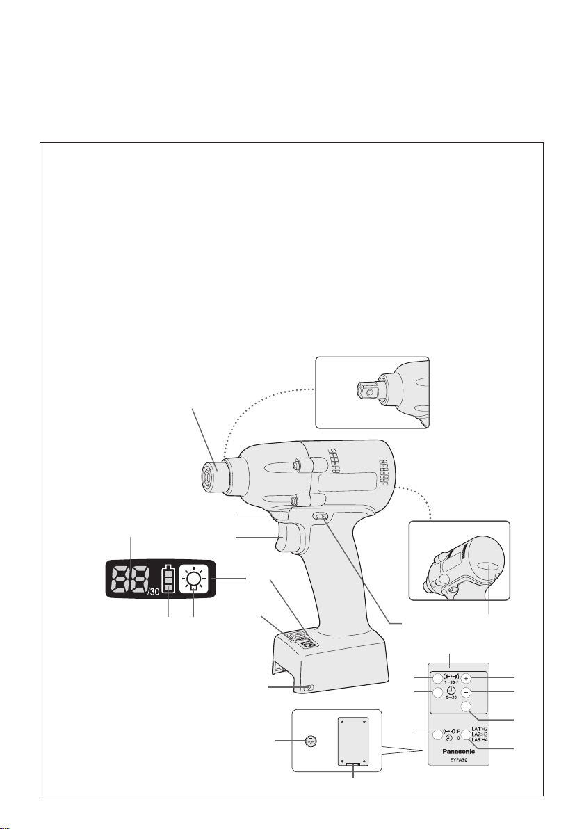
FUNCTIONAL DESCRIPTION
FUNKTIONSBESCHREIBUNG
DESCRIPTION DES FONCTIONS
DESCRIZIONE DELLE FUNZIONI
FUNCTIEBESCHRIJVING
DESCRIPCIÓN FUNCIONAL
FUNKTIONSBESKRIVELSE
FUNKTIONSBESKRIVNING
FUNKSJONSBESKRIVELSE
TOIMINTAKUVAUS
ФУНКЦИОНАЛЬНОЕ ОПИСАНИЕ
ФУНКЦIОНАЛЬНИЙ ОПИС
POPIS FUNKCÍ
(A)
EYFLA2Q
EYFLA3J
EYFLA1A
EYFLA2A
(K)
(I)
Remote control and battery are not included.
Fernbedienung und Batterie werden nicht mitgeliefert.
La télécommande et la batterie ne sont pas incluses.
Telecomando e batteria non in dotazione.
Afstandsbediening en batterij zijn niet bijgeleverd.
El control remoto y la batería no están incluídos.
Fjernbetjening og batteri medfølger ikke.
Fjärrkontroll och batteri medföljer ej.
Fjernkontroll og batteri er ikke inkludert.
Kaukosäädin ja paristo eivät kuulu varusteisiin.
Пульт дистанционного управления и батарея не входят в комплект.
Пульт дистанційного управління і батарея не входять до комплекту.
Dálkové ovládání a baterie nejsou obsaženy v balení.
(J)
(F)
(E)
(G)(H)
(D)
(S)
-
2 -
(R)
(U)
(T)
(Q)
(C)
(B)
(L)
(M)
(N)
(O)
(P)
Page 3

6.35 mm (1/4") hex quick connect chuck (EYFLA1A, EYFLA2A)/square drive (EYFLA2Q, EYFLA3J/Pin type)
6,35 mm (1/4") Sechskant-Schnellaufspannfutter (EYFLA1A, EYFLA2A)/Vierkant (EYFLA2Q, EYFLA3J/Stifttyp)
Mandrin de connexion rapide hexagonal de 6,35 mm (1/4")/entraînement carré (EYFLA2Q, EYFLA3J/Type à goujon)
Mandrino esagonale di collegamento rapido da 6,35 mm (1/4")/attacco quadro (EYFLA2Q, EYFLA3J/Tipo con piolo)
6,35 mm zeskantboorkop met snelkoppeling/vierkante aandrijving (EYFLA2Q, EYFLA3J/pen-type)
Mandril hexagonal de conexión rápida de 6,35 mm (1/4")/Excitador cuadrado (EYFLA2Q, EYFLA3J/tipo pasador)
6,35 mm (1/4") hexagonal borepatron til hurtig tilslutning/rkantet drev (EYFLA2Q, EYFLA3J/stifttype)
(A)
Snabbchuck med 6,35 mm sexkantshylsa/fyrkantskoppling (EYFLA2Q, EYFLA3J/stifttyp)
6,35 mm (1/4") hex hurtigtilkoplingschuck/rkantdrev (EYFLA2Q, EYFLA3J/pinnetype)
6,35 mm (1/4") kuusiopikaistukka/neliöavain (EYFLA2Q, EYFLA3J/nastatyyppi)
6,35 мм (1/4") шестигранный патрон быстрого подсоединения/квадратный хвостовик (EYFLA2Q, EYFLA3J/Штифтового типа)
6,35 мм (1/4") шестигранний патрон швидкого приєднання/квадратний хвостовик (EYFLA2Q, EYFLA3J/Штифтового типу)
6,35 mm (1/4“) Svěrací šroub s vnějším šestihranným nástavcem (EYFLA1A, EYFLA2A)/ vnitřní čtyřhran (EYFLA2Q, EYFLA3J/ typ s kontaktním kolíkem)
Tightening conrmation lamp
Anzugsbestätigungslampe
Témoin de conrmation de serrage
Spia conferma serraggio
Aanhaaltoestand-bevestigingslampje
Lámpara de conrmación de apriete
Lampe til bekræftelse af stramning
(B)
Lampa för bekräftad åtdragning
Strammebekreftelseslampe
Kiristyksen varmistuslamppu
Лампочка подтверждения затяжки
Лампочка підтвердження затяжки
Kontrolka utažení
Alignment mark
Ausrichtmarkierungen
Marques d’alignement
Marcature allineamento
Uitlijntekens
Marcas de alineación
Flugtemærker
(D)
Anpassningsmärken
Opprettingsmerke
Sovitusmerkit
Метки совмещения
Мітки вирівнювання
Značka zarovnání
Control panel
Bedienfeld
Panneau de commande
Pannello di controllo
Bedieningspaneel
Panel de control
Kontrolpanel
(F)
Kontrollpanel
Kontrollpanel
Säätöpaneeli
Панель управления
Панель управління
Kontrolní panel
Forward/Reverse lever
Vorwärts-/Rückwärtshebel
Levier d’inversion marche avant/marche arrière
Leva di avanzamento/inversione
Links/rechtsschakelaar
Palanca de avance/marcha atrás
Greb til forlæns/baglæns retning
(C)
Riktningsomkopplare
Forover-/bakoverbryter
Eteenpäin/taaksepäin vipu
Рычаг переключения вперед/назад
Важіль перемикання вперед/назад
Spínač předního a zpětného chodu
Remote control receiver
Fernbedienungsempfänger
Récepteur de la télécommande
Ricevitore telecomando
Afstandsbedieningontvanger
Receptor de control remoto
Fjernbetjeningsmodtager
(E)
Fjärrstyrningsgivare
Fjernkontrollmottaker
Kaukosäätimen vastaanotin
Датчик дистанционного управления
Датчик дистанційного управління
Přijímač signálu dálkového ovládání
LED light on/off button
LED-Leuchten-EIN/AUS-Taste
Bouton Marche/Arrêt de la lumière DEL
Tasto di accensione e spegnimento della luce LED
Aan/uit-toets (ON/OFF) voor LED-lampje
Botón ON/OFF de luz LED
TÆND/SLUK-knap til LED-lys
(G)
Strömbrytare för LED-ljus
PÅ/AV-knapp for LED-lys
LED-valon kytkin/katkaisupainike
Кнопка включения/выключения светодиодной подсветки
Кнопка ввімкнення/вимкнення світлодіодного підсвічування
Spínač zap./vyp. elektroluminiscenční diody LED
-
3 -
Page 4

Battery indication lamp
Akku-Anzeigelampe
Témoin indicateur de la batterie
Spia livello batteria
Accu-indicatielampje
Lámpara de indicadora de la batería
Batteriindikatorlampe
(H)
Batteriindikator
Batteriindikasjonslampe
Akun osoituslamppu
Индикаторная лампочка батареи
Індикаторна лампочка батареї
Kotrolka stavu baterie
Variable speed control trigger
Variabler Geschwindigkeitskontrollschalter
Gâchette de commande de vitesse
Grilletto di controllo velocità variabile
Startschakelaar met variabele toerentalregeling
Disparador del control de velocidad variable
Kontroludløser for variabel hastighed
(J)
Avtryckare med variabel varvtalsreglering
Trinnløs hovedbryter
Nopeudensäätökytkin
Переключатель регулировки переменной скорости
Перемикач регулювання змінної швидкості
Spoušť rychlostní regulace
Remote control
Fernbedienung
Télécommande
Telecomando
Afstandsbediening
Control remoto
Fjernbetjening
(L)
Fjärrkontroll
Fjernkontroll
Kaukosäädin
Пульт дистанционного управления
Пульт дистанційного управління
Dálkové ovládání
− button
Taste –
Bouton −
Tasto −
− toets
Botón
−
− knap
(N)
Knapp (−)
− knapp
− painike
Кнопка −
Кнопка −
Tlačítko −
Display
Anzeige
Afchage
Display
Display
Visor
Display
(I)
Indikeringsfönster
Display
Näyttö
Дисплей
Дисплей
Displej
LED light
LED-Leuchte
Lumière DEL
Luce LED
LED-lampje
Luz indicadora
LED-lys
(K)
LED-ljus
LED-lys
LED-valo
Светодиодная подсветка
Світлодіодне підсвічування
Světlo LED
+ button
Taste +
Bouton +
Tasto +
+ toets
Botón +
+ knap
(M)
Knapp (+)
+ knapp
+ painike
Кнопка +
Кнопка +
Tlačítko +
OK button
Taste OK
Bouton OK
Tasto OK
OK toets
Botón OK (correcto)
OK-knap
(O)
Bekräftelseknapp
OK knapp
OK-painike
Кнопка OK
Кнопка OK
Tlačítko OK
-
4 -
Page 5

Torque level button
Anzugsmomentstufentaste
Bouton de niveau du couple de serrage
Tasto livello coppia
Aanhaalmoment-niveautoets
Botón de palanca de par de torsión
Knap til stramningsmomentniveau
(P)
Väljare för momentnivå
Dreiemomentknapp
Vääntömomentin tasopainike
Кнопка уровня крутящего момента
Кнопка рівня крутильного моменту
Tlačítko regulace hladiny točivého momentu
Holder
Halter
Support
Supporto
Houder
Retenedor
Holder
(R)
Hållare
Holder
Pidin
Держатель
Держак
Držák
Interval set button
Intervall-Einstelltaste
Bouton de réglage de l’intervalle
Tasto impostazione intervallo
Interval-insteltoets
Botón de ajuste de intervalo
Intervalindstillingsknap
(T)
Intervallinställningsknapp
Intervallinnstillingsknapp
Jakson säätöpainike
Кнопка установки интервала
Кнопка встановлення інтервалу
Tlačítko intervalového nastavení
Format button
Formattaste
Bouton de format
Tasto formato
Formatteertoets
Botón de formato
Formatknap
(Q)
Formateringsknapp
Format knapp
Formaatin painike
Кнопка формата
Кнопка формату
Rázové tlačítko
Battery
Batterie
Batterie
Batteria
Accu
Batería
Batteri
(S)
Batteri
Batteri
Akku
Батарея
Батарея
Baterie
Torque set button
Anzugsmoment-Einstelltaste
Bouton de réglage du couple de serrage
Tasto impostazione coppia
Aanhaalmoment-insteltoets
Botón de ajuste de par de torsión
Knap til indstilling af stramningsmoment
(U)
Momentinställningsknapp
Dreiemomentinnstillingsknapp
Vääntömomentin säätöpainike
Кнопка установки крутящего момента
Кнопка встановлення крутильного моменту
Tlačítko nastavení hladiny točivého momentu
-
5 -
Page 6
I
. INTENDED USE
This tool is a Cordless Impact Driver/Wrench
and can be used to tighten bolts, nuts, and
screws. Additionally, it provides a torque control function that automatically stops tool oper-
ation when a preset load is reached to deliver
consistent tightening torque.
Read “the Safety Instructions” booklet
and the following before using.
II
.
ADDITIONAL SAFETY
RULES
1
) Wear ear protectors when using the
tool for extended periods.
2)
Be aware that this tool is always in an
operating condition, since it does not have
to be plugged into an electrical outlet.
3)
When screwing or driving into walls, floors,
etc., “live” electrical wires may be encountered. DO NOT TOUCH THE HEX QUICK
CHUCK OR ANY FRONT METAL PARTS
OF THE TOOL! Hold the tool only by the
plastic handle to prevent electric shock in
case you screw or drive into a “live” wire.
4)
Do NOT operate the Forward/Reverse
lever when the main switch is on. The battery will discharge rapidly and damage to
the unit may occur.
5)
During charging, the charger may become
slightly warm. This is normal.
D
o NOT charge the battery for a long period.
6) When storing or carrying the tool, set the
Forward/Reverse lever to the center position (switch lock).
Do not strain the tool by holding the speed
7)
control trigger halfway (speed control
mode) so that the motor stops.
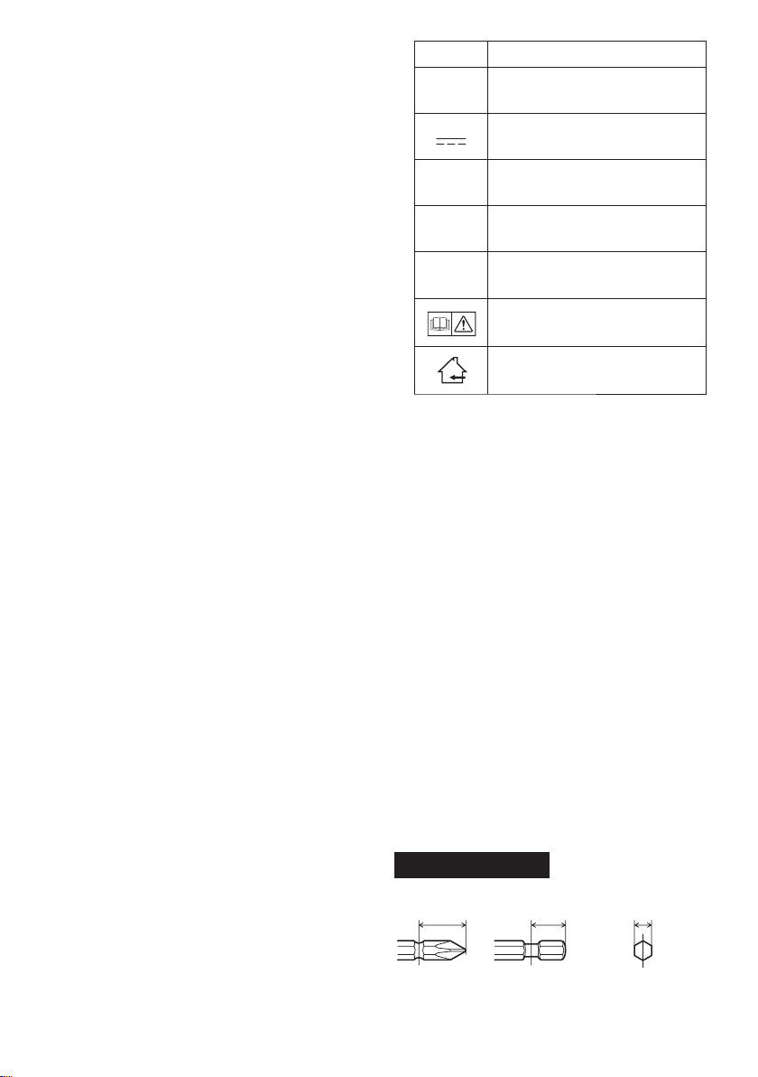
Symbol Meaning
V
n
0
Revolutions or reciprocations
-1
… min
Ah
III
. ASSEMBLY
Electrical capacity of battery
instructions before use.
Volts
Direct current
No load speed
per minutes
pack
Read the operating
For indoor use only.
Attaching or Removing Bit
NOTE:
•
When attaching or removing a bit, disconnect battery pack from tool or place the
switch in the center position (switch lock).
1. Hold the collar of quick connect chuck and
pull it out from the tool.
2.
Insert the bit into the chuck. Release the
collar.
The collar will return to its original position
3.
when it is released.
Pull the bit to make sure it does not come out.
4.
5. To remove the bit, pull out the collar in the
same way.
CAUTION:
•
If the collar does not return to its origi-
nal position or the bit comes out when
pulled on, the bit has not been properly
attached. Make sure the bit is properly
attached before use.
EYFLA1A/EYFLA2A
12 mm
(15/32")
9 mm – 9.5 mm
(23/64" – 3/8")
6.35 mm
(1/4")
-
6 -
Page 7
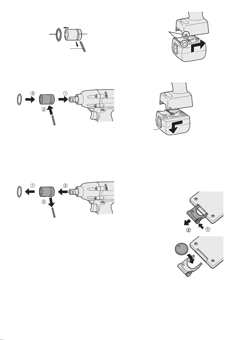
Attaching Socket
• Remove the socket’s rubber ring and pin.
ring
rubber
pin
1 Attach the socket to the tool.
2 Insert
3 A
the pin. (Taking care to align the pin
holes on the socket and tool.)
ttach the rubber ring by sliding it into place
over the groove.
groove
Alignment
marks
2. To remove the battery pack:
Push up on the button from the front to re-
lease the battery pack.
NOTE:
Be sure to attach the rubber ring to prevent
the pin from falling out.
Removing Socket
1 Remove the rubber ring.
2 Remove the pin.
emove the socket from the tool.
3 R
NOTE:
Keep the temperature of the tool above
the
freezing point (0°C/32°F) when attach-
ing sockets to or detaching them from
the square drive on the tool. Do not use
excessive
ing sockets.
force when attaching or detach-
Attaching or Removing Battery Pack
1. To connect the battery pack:
Line up the alignment marks and attach
the battery pack.
•
Slide the battery pack until it locks into
position.
Button
IV
. OPERATION
Before Using the Remote
Control (Available as an
optional accessory)
Insert the battery
1. Pull out the battery holder.
1 P
ush in on the fas-
tener as indicated by
the arrow.
2 Pull out the holder
2. Insert the battery and
push the holder
back in.
NOTE:
If the tool does not respond to the wire-
•
less remote control even when the remote
control is operated close to the tool, the
battery (CR2025) is dead. Replace it with
a fresh battery.
The included battery is provided for sam-
•
ple use and may not last as long as commercially available batteries.
.
-
7 -
Page 8
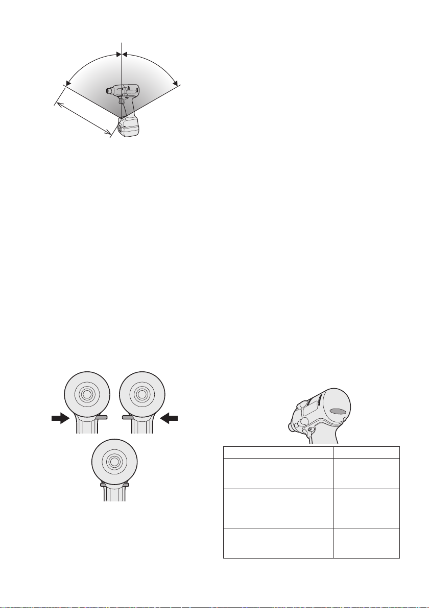
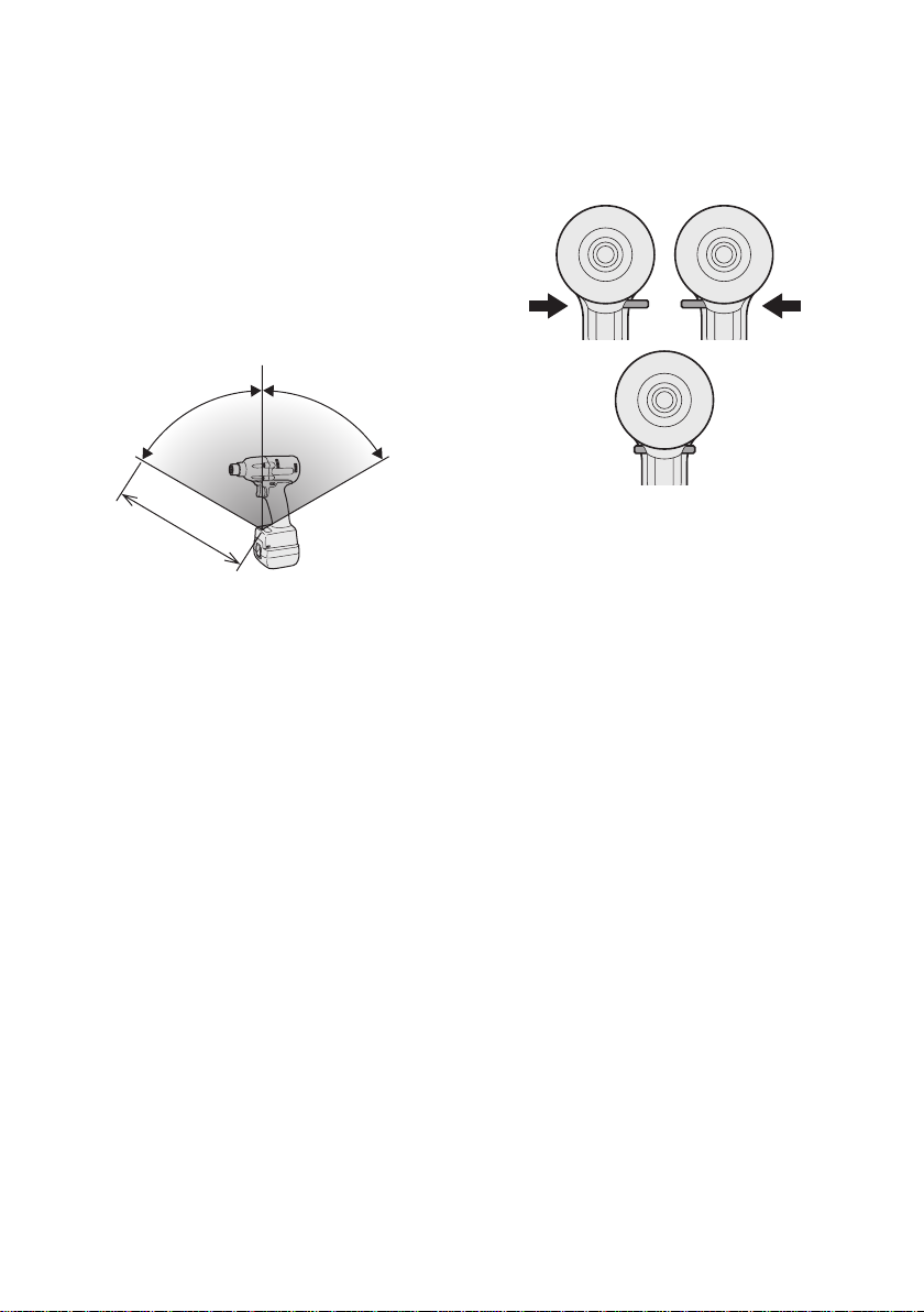
Wireless remote control range
Approx. 50 cm
Vertically
A
p
p
r
o
x
.
6
0
°
A
p
p
r
o
x
.
6
0
°
Forward Reverse
Switch lock
The remote control should be operated within
approximately 50 cm and approximately 60°
vertically and horizontally of the perpendicular
relative to the infrared receiver on the tool.
Under the following circumstances, you may
•
not be able to operate the tool, even within
this range.
If there is an object between the remote
•
control’s transmitter and the tool’s receiver.
•
Use outdoors or in other environments
where the remote control receiver is
exposed to a strong light source, or when
the remote control transmitter or receiver is
dirty may cause the tool to fail to respond,
even when the remote control is used within
the operating range.
[Main Body]
Switch and Forward/Reverse
Lever Operation
Forward Rotation Switch
Operation
1. Push the lever for forward rotation.
2. Depress the trigger switch slightly to start
the tool slowly.
The speed increases with the amount of
3.
depression of the trigger for efficient tight-
ening of screws. The brake operates and
the bit stops immediately when the trigger
is released.
4.
After use, set the lever to its center posi-
tion (switch lock).
Reverse Rotation Switch
Operation
1.
Push the lever for reverse rotation. Check
direction of rotation before use.
Depress the trigger switch slightly to start the
2.
tool slowly.
3. After use, set the lever to its center position (switch lock).
CAUTION:
•
To eliminate excessive temperature
increase of the tool surface, do not
operate the tool continuously using two
or more battery packs. Tool needs cool
off time before switching to another
pack.
Tightening confirmation lamp
• The tightening confirmation lamp can be
used to check whether the torque control
function was activated.
the
CAUTION:
To prevent damage, do not operate
Forward/Reverse lever until the bit comes
to a complete stop.
Tool status Lamp display
Tightening complete
(with torque control
function operation)
Tightening not complete
•
• Tightening complete
with retightening within 1
second
The automatic stop
function has been
activated.
-
8 -
Green
(For approx. 2
seconds)
Red
(For approx. 2
seconds)
Red
(For approx. 5
minutes)
Page 9
CAUTION:
• When the tool stops automatically after
the switch is released during impactmode tightening and then reengaged
within 1 second, the red lamp will light up
to indicate the risk of excessive torque
application as a result of retightening.
NOTE
•
The tightening confirmation lamp will not
turn on under the following conditions:
When the torque clutch is set to “F”
•
• During reverse rotation operation
• The lamp turns off when the tool is in
operation.
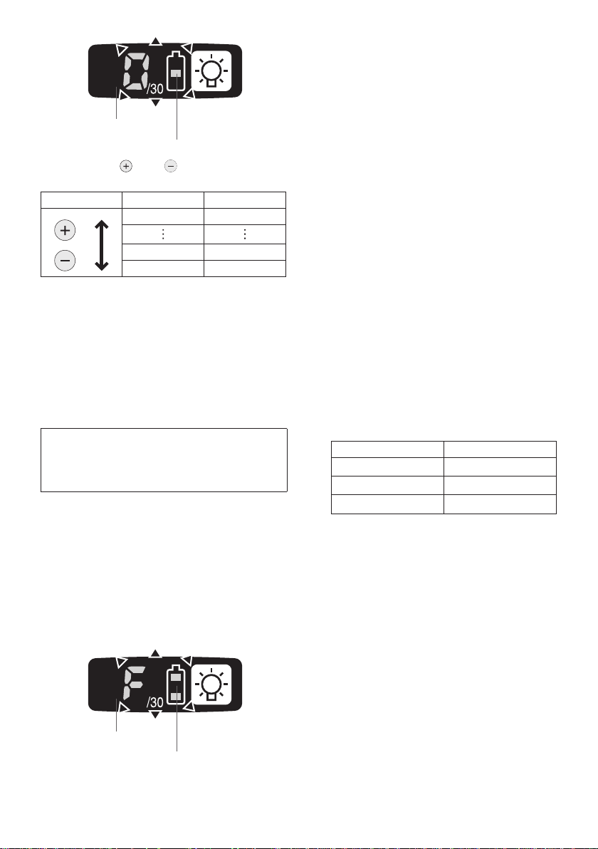
Control Panel
(2) The battery indication lamp
• Use the battery indication lamp to check
how much power is left in the battery.
Battery life varies slightly with ambient tem-
•
perature and battery characteristics. The
lamp is designed to provide a rough indica-
tion of remaining battery life.
Battery indication lamp
Indicator Battery status
Fully charged
Approx. 40% or less
remaining
(1) (2) (3)
(1) LED light
Pressing the button toggles the LED light on
and off.
The light illuminates with very low current, and
it does not adversely affect the performance
tool during use or its battery capacity.
the
CAUTION:
The built-in LED light is designed to illu-
•
minate the small work area temporarily.
Do not use it as a substitute for a regu-
•
flashlight, since it does not have
lar
enough brightness
Caution : DO NOT STARE INTO BEAM.
Use of controls or adjustments or performance
of procedures other than those specied herein
may result in hazardous radiation exposure.
.
of
Flashing
Approx. 20% or less
remaining (indicates need
to recharge battery)
Flashing
Flashing
The battery pack will need
to be charged soon.
No charge
The battery pack needs to
be charged.
(The tool’s automatic
power-off function will
activate at this stage.)
Automatic power-off function
• The automatic power-off function is designed
to prevent a loss of tightening torque due
to reduced battery voltage. Once it has
been activated, the tool will not operate until
the battery pack has been charged (or replaced with a fresh unit), even if the trigger is
depressed.
Battery indication lamp
Indicator
-
9 -
Flashing
Page 10
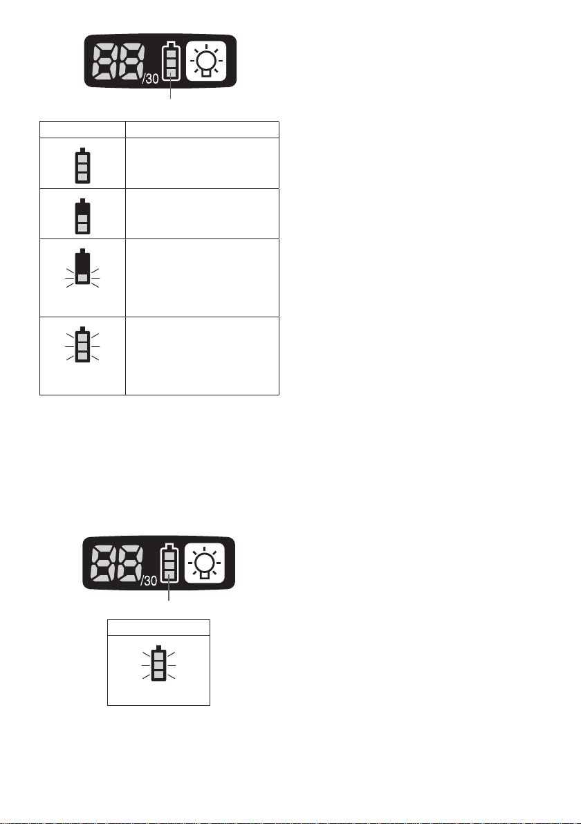
NOTE:
• All 3 bars on the battery indication lamp
will flash when the automatic power-off
function is activated.
When the battery indication lamp begins
•
flashing, the battery pack should be
charged (or replaced with a fresh unit)
immediately.
Be sure to fully charge the battery pack
•
in question after activation of the automatic power-off function. Failure to do
so may prevent the automatic power-off
function from being properly deactivated.
(3) The torque control function
• The torque control function calculates the
load from the motor’s rotational angle during
the hammer impact and determines that the
bolt has been properly seated when a preset load value is exceeded. Driving is then
automatically stopped after a preset number
of impacts have been delivered to the bolt.
CAUTION:
Always check the tool’s tightening torque
•
before use. Improper tool operation may
result in excessive or inadequate tightening.
CAUTION:
•
Always operate the tool with the switch
fully engaged. The torque control func-
tion will not operate when the switch is
not sufficiently engaged, preventing the
tool from stopping automatically.
In work where a heavy load comes to
•
bear during tightening, the load may be
interpreted as the seating of the bolt,
preventing the bolt from being com-
pletely tightened.
Repeated tightening of the same bolt
•
may break the bolt or deform the material into which the bolt is being driven as
a result of excessive tightening.
The tightening torque value and preci-
•
sion vary with factors such as the mate-
rial into which the bolt is being driven
and the condition of the socket being
used. Adjust the torque as necessary
for the work being performed. Bolt tightening torque varies due to the factors
described below.
1) Bolt
Bolt diameter: Tightening torque gener-
•
ally increases with bolt diameter.
•
Torque coefficient (indicated by the bolt
manufacturer), grade, length, etc.
2
) Other
• Bit and socket condition: Material,
amount of play, etc.
Use of a universal joint or socket
•
adapter
•
User: Manner in which the tool is
applied to the bolt, strength with which
the tool is held, manner in which the
tool’s switch is engaged
Condition of object being tightened: Ma-
•
terial, seating surface finish
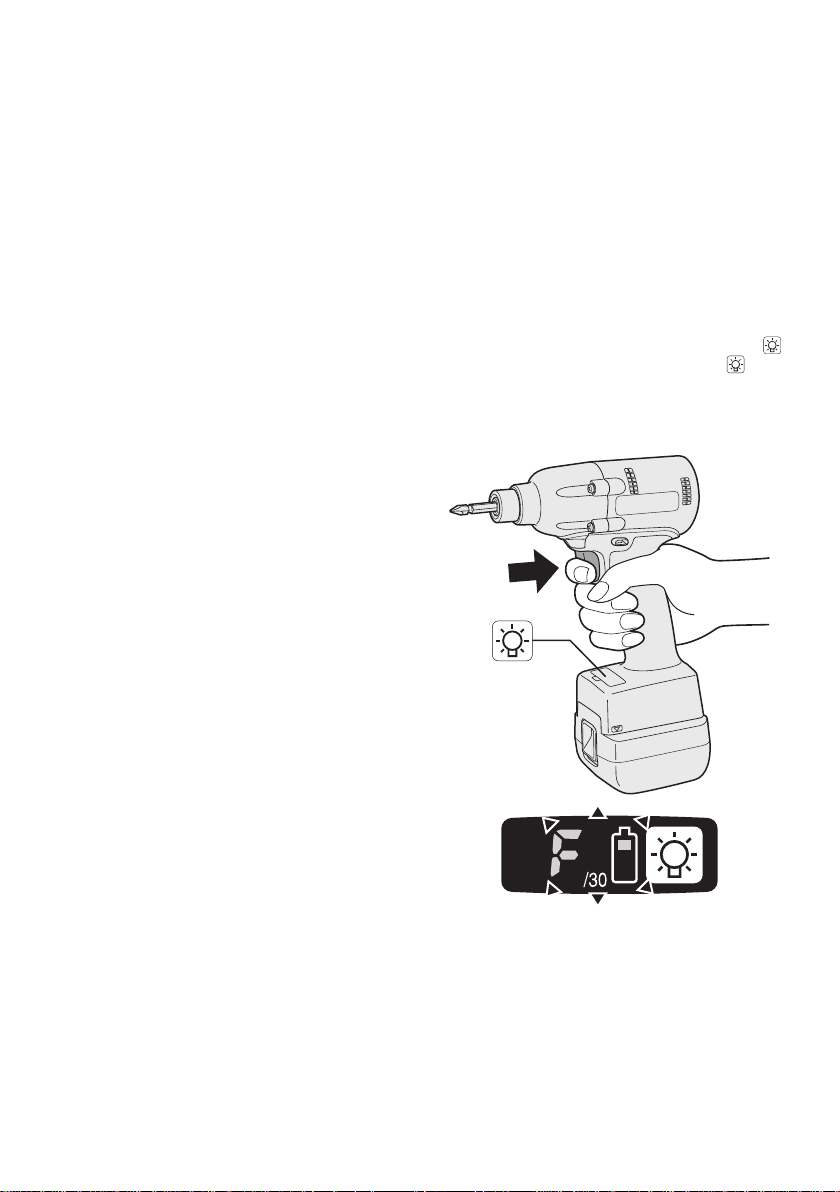
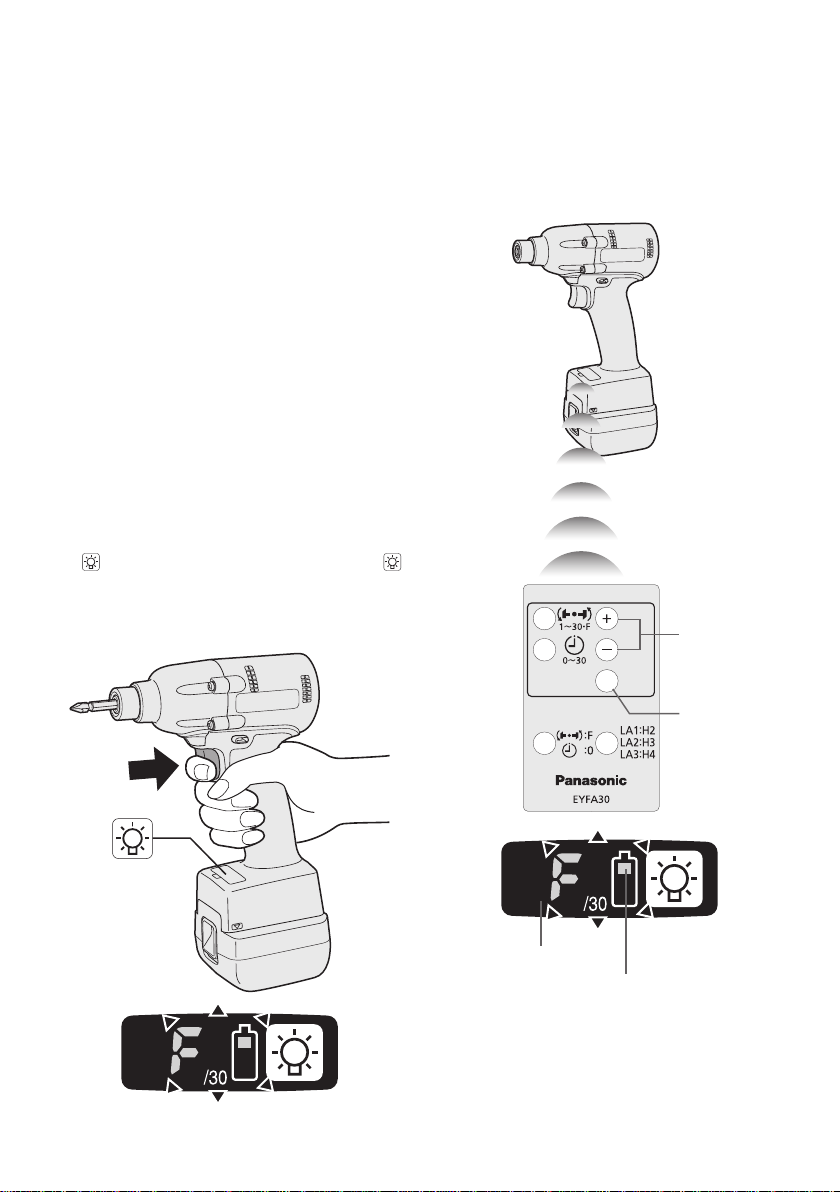
Setting the tool to configuration mode
1.
Turn off the control panel.
• If the control panel is on, remove and
then reinsert the battery pack.
Engage the switch while pushing the
2.
button and then release both the
ton and the switch.
After all the LED lamps have turned off,
•
the control panel will flash and change
to configuration mode.
NOTE:
• Tools ship from the factory set to “F”
mode (torque control function off).
•
The control panel will turn off if the tool
is not operated for a period of 5 min-
utes.
but-
-
10 -
Page 11
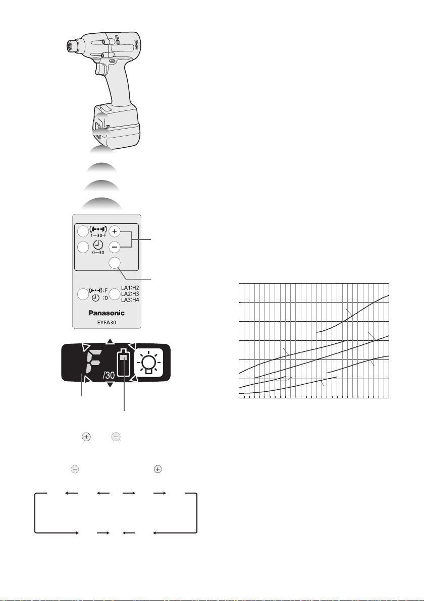
Configuring the torque clutch setting
3…28
1F30 229
0
10
20
30
40
50
60
EYFLA1 (M6)
EYFLA2 (M6)
EYFLA1 (M8)
EYFLA2 (M8)
EYFLA3 (M8)
EYFLA3 (M10)
N • m
1 2 3 4 5 6 7 8 9 10 1112131415 1617181920 212223242526272829 30
(1)
(2)
You can select from 30 torque clutch
•
settings (1 to 30).
•
Use figures from the Tightening Torque
Chart to guide your selection of torque
clutch setting. (See the following tightening torque chart)
Press the OK button to accept the select-
2.
ed torque clutch setting.
The control panel will stop flashing and
•
light up.
CAUTION:
•
You must press the OK button in order
for the selected setting to take effect.
•
Be sure to verify the new value after
changing the setting. (See page 12.)
Tightening Torque Chart (for Reference
Use)
The values illustrated on this chart were measured under the conditions described below
and are provided for reference purposes.
Actual tightening torque varies with ambient
conditions (the particular bolt being tightened,
hardware being used, method of holding the
bolt in place, etc.).
Display
Battery indication lamp
1. Press the and buttons to select the
clutch setting that is appropriate for the
work being performed.
is pressed
• “F” indicates that the torque control func-
tion is off.
As the button
As the button
is pressed
Measurement conditions
• Temperature: Room temperature (20°C/68°F)
Using the Interval Set
•
The interval set operates to prevent the tool
from operating after it automatically stops as
a result of the torque control function, even if
the switch is engaged.
1.
Set the tool to configuration mode.
(See page 10.)
2. Press the interval set button.
• The control panel will begin flashing.
Display: The number 0 ashes on and off.
Battery indication lamp: The middle bar
of the battery ashes on and off.
11 -
-
Page 12
Display
Battery indication lamp
3. Press the and buttons to set the
desired time.
Buttons Display Seconds
30 3
1 0.1
0 Off
4.
Press the OK button to accept the selected
setting.
The control panel will stop flashing and
•
light up, and the torque clutch setting
will be displayed.
CAUTION:
•
Be sure to verify the new value after
changing the setting.
Initializing All Settings
Factory settings
• Torque clutch setting: “F” (torque con-
trol function off)
•
Interval setting: 0 (off)
• This section explains how to revert all tool
settings to their default values at the time of
shipment from the factory.
The error display will be turned off.
•
1. Set the tool to configuration mode.
(See page 10.)
2. Press the format button.
• The control panel will begin flashing.
Display: The letter “F” ashes on and off.
Battery indication lamp: The upper and
lower bars of the battery ash on and off.
The control panel will stop flashing and
•
light up.
Checking Tool Settings
This section describes how to have the tool
•
display current settings for approximately 3
seconds when the tool is stopped.
You cannot check tool settings when the
•
control panel is turned off. First, engage
the switch briefly to reactivate the display.
Checking the torque clutch setting
Press the torque set button.
1.
• Control panel display
Display: The torque set lights up.
Battery indication lamp: The upper bar of
the battery ashes on and off.
Checking the interval
Press the interval set button.
1.
• Control panel display
Display: The interval set lights up.
Battery indication lamp: The middle bar
of the battery ashes on and off.
Checking tool circuits
Press the torque set button.
1.
• Control panel display
Display: The torque set display lights up.
Battery indication lamp: The middle and
lower bars of the battery ash on and off.
Display Tool circuit
H2 EYFLA1
H3 EYFLA
H4 EYFLA3
NOTE:
• If you engage the switch while a setting
is being displayed, the control panel will
revert to the torque clutch setting display.
CAUTION:
The torque set display is not intended
•
to be used to identify the type of drive
component parts (hammer, etc.) used
in a particular tool.
2
Display
Battery indication lamp
3. Press the OK button to accept the select-
ed setting.
-
12 -
Page 13
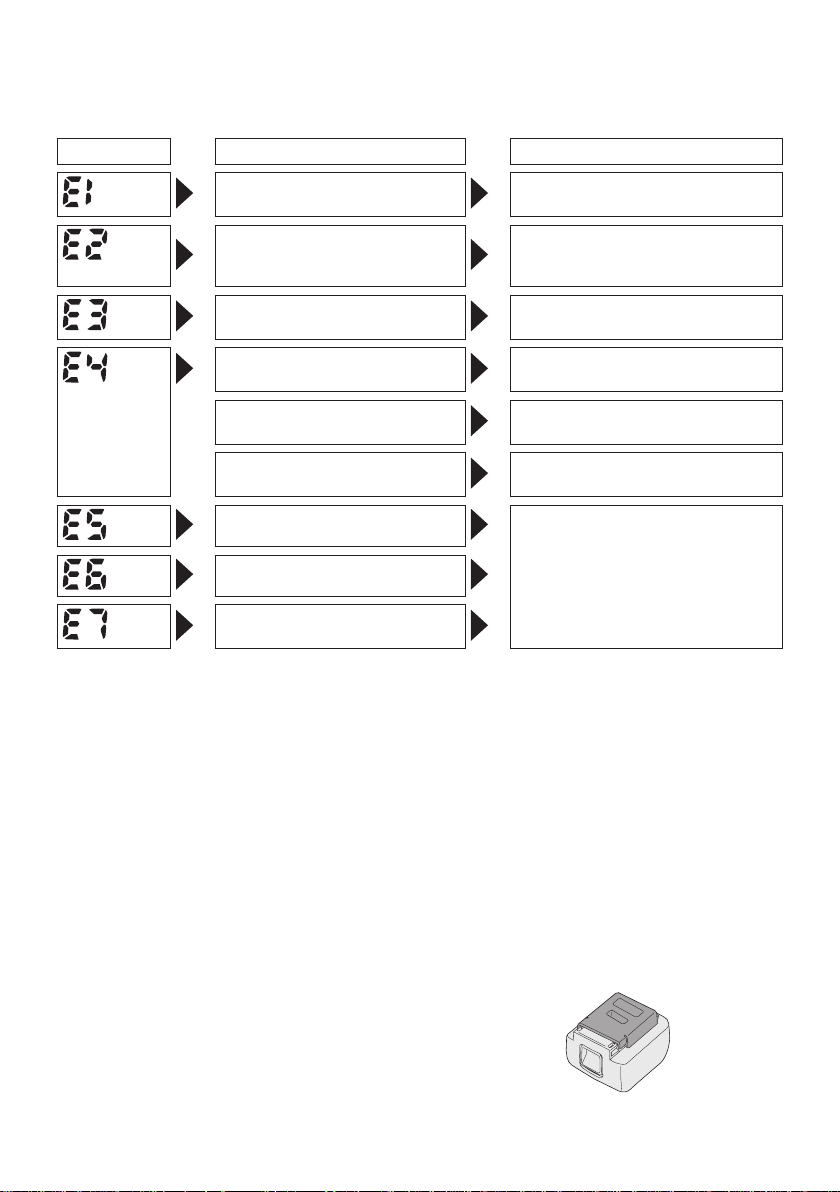
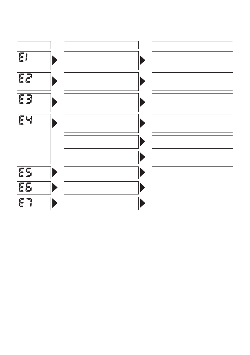
Error Display
In the event of a tool or battery pack malfunction, the control panel will display an error message.
Please check the tool or battery pack as described in the following chart before having them
serviced.
Display Likely cause Corrective action
Setting error Re-initialize the tool using the
The battery pack is too hot. Stop work and allow the battery
The tool is too hot to operate. Stop work and allow the tool to
The contacts that connect the
battery pack and tool are dirty.
The battery pack has not been
properly inserted into the tool.
The pins on either the tool or
battery pack have worn down.
Motor failure, etc. Stop using the tool immediately.
Sensor malfunction, failure, etc.
Tool circuit malfunction, failure,
etc.
[Battery Pack]
For Appropriate Use of Bat-
tery Pack
Li-ion Battery Pack (EYFB30)
• For optimum battery life, store the Li-ion bat-
tery pack following use without charging it.
When charging the battery pack, confirm
•
that the terminals on the battery charger
are free of foreign substances such as dust
and water etc. Clean the terminals before
charging the battery pack if any foreign substances are found on the terminals.
T
he life of the battery pack terminals may be
affected by foreign substances such as dust
and water etc. during operation.
remote control. (See page 12.)
pack to cool before resuming use
of the tool.
cool before resuming use.
Remove any dirt.
Insert the battery pack rmly into
the tool.
Replace the battery pack.
• When battery pack is not in use, keep it
away from other metal objects like: paper
clips, coins, keys, nails, screws, or other
small metal objects that can make a con-
nection from one terminal to another.
Shorting
cause sparks, burns or a fire.
When operating the battery pack, make sure
•
the work place is well ventilated.
•
When the battery pack is removed from the
main body of the tool, replace the battery
pack cover immediately in order to prevent
dust or dirt from contaminating the battery
terminals and causing a short circuit.
the battery terminals together may
-
13 -
Page 14
Battery Pack Life
The rechargeable batteries have a limited life.
If the operation time becomes extremely short
after recharging, replace the battery pack with
a new one.
[Battery Charger]
Charging
Read the operating manual for Panasonic battery
charger for the battery pack before charging.
Battery Recycling
ATTENTION:
For environmental protection and recycling
of materials, be sure that it is disposed of
at an ofcially assigned location, if there is
one in your country.
Before charging the battery
When charging EYFB30:
Charge the battery at a temperature of 5°C
(41°F) to 40°C (104°F).
he battery pack cannot be charged at a tem-
T
perature of less than 5°C (41°F)
perature of the battery pack is less than 5°C
(41°F), rst remove the battery pack from
the charger and allow it to sit for an hour in a
location where the temperature is 5°C (41°F) or
warmer. Then charge the battery pack again.
. If the tem-
Information for Users on Collection and Disposal of Old Equipment and used Batteries
These symbols on the products, packaging, and/or accompanying documents
mean that used electrical and electronic products and batteries should not be
mixed with general household waste.
or proper treatment, recovery and recycling of old products and used batteries,
F
please take them to applicable collection points, in accordance with your national
legislation and the Directives 2002/96/EC and 2006/66/EC.
By disposing of these products and batteries correctly, you will help to save valuable
resources and prevent any potential negative effects on human health and the
nvironment which could otherwise arise from inappropriate waste handling.
e
For more information about collection and recycling of old products and batteries,
please contact your local municipality, your waste disposal service or the point of
sale where you purchased the items.
enalties may be applicable for incorrect disposal of this waste, in accordance with
P
national legislation.
For business users in the European Union
If you wish to discard electrical and electronic equipment, please contact your dealer or
supplier for further information.
[Information on Disposal in other Countries outside the European Union]
These symbols are only valid in the European Union. If you wish to discard these items,
please contact your local authorities or dealer and ask for the correct method of disposal.
Note for the battery symbol (bottom two symbol examples):
This symbol might be used in combination with a chemical symbol. In this case it complies
with the requirement set by the Directive for the chemical involved.
-
14 -
Page 15
V.
MAINTENANCE
Use only a dry, soft cloth for wiping the unit.
Do not use a damp cloth, thinner, benzine, or
other volatile solvents for cleaning.
VII
. SPECIFICATIONS
VI
. ACCESSORIES
Charger
• EY0L80
Battery pack
•
EYFB30
Remote control
•
EYFA30
Protector for tool
•
EYFA01-A (Blue)
• EYFA01-Y (Yellow)
• EYFA01-H (Gray)
Protector for battery
EYFA02-H
•
MAIN UNIT
Model EYFLA1 EYFLA2 EYFLA3
A A Q J
Moter 10.8 V DC
Chuck size Single-
No load
speed
Impact per
minute
Maximum torque 40 N·m
Torque control function
operating range
Overall length 158 mm (6-7/32") 164 mm (6-7/16")
Weight (with battery
pack: EYFB30)
ended
Doubleended
Stage 1
Stage 1
9 – 9.5 mm
(23/64" – 3/8")
12 mm (15/32") 1
2
3 – 5
6
7
8
9 – 30·F
2
3 – 5
6
7
8
9 – 30·F
(408 kgf-cm, 354 in-lbs)
Approx. 3 – 22 N·m
(31 –
27 – 195 in-lbs)
0 – 950
0 – 1000
0 – 1050
0 – 1300
0 – 1450
0 – 1550
0 –
0 – 1900
0 – 1950
0 –
0 – 2500
0 – 2800
0 – 3000
0 – 4000
224 kgf-cm,
2300
2100
1.3 kg (2.8 lbs) 1.35 kg (2.9 lbs)
9 – 9.5 mm
(23/64"
– 3/8")
2 mm
(15/32")
1
2
3
4 – 30·F
1
2
3
4 – 30·F
90 N·m
(918 kgf-cm, 796 in-lbs)
Approx. 6 – 30 N·m
(61 – 306 kgf-cm,
53 – 266 in-lbs)
□
9.5 mm
(3/8")
0 – 1300
0 – 1450
0 – 1550
0 – 2300
0 – 2500
0 – 2800
0 – 3000
0 – 3600
□
12.7 mm (1/2")
0 – 2300
0 – 3000
1
20 N·m (1224 kgf-cm,
1062 in-lbs)
Approx. 16 – 53 N·m
(163 – 540 kgf-cm,
142 – 469 in-lbs)
-
15 -
Page 16
BATTERY PACK (not included with shipment)
Model EYFB30
Storage battery Li-ion battery
Battery voltage 10.8 V DC (3.6 V/6 cells)
Capacity 3 Ah
BATTERY CHARGER (not included with shipment)
Model EY0L80
Rating See the rating plate on the bottom of the charger.
Weight 0.95 kg (2.1 lbs)
[Li-ion battery pack]
10.8 V
Charging time
3 Ah
EYFB30
Usable: 40 min.
Full: 65 min.
Remote control (not included with shipment)
Model EYFA30
Battery voltage 3 V DC
Dimensions 54 mm (2-1/8") × 86 mm (3-3/8") × 10 mm (13/32”)
Weight (with battery) Approximately 29 g (0.6 lbs)
-
16 -
Page 17
ONLY FOR U. K.
VIII
.
ELECTRICAL PLUG
INFORMATION
FOR YOUR SAFETY PLEASE READ
THE FOLLOWING TEXT CAREFULLY
This appliance is supplied with a moulded
three pin mains plug for your safety and
convenience.
A 5 amp fuse is tted in this plug.
Should the fuse need to be replaced please
ensure that the replacement fuse has a rat-
ing of 5 amp and that it is approved by ASTA
or BSI to BS1362.
Check for the ASTA mark
on the body of the fuse.
If the plug contains a removable fuse cover
you must ensure that it is retted when the
fuse is replaced.
If you lose the fuse cover the plug must not
be used until a replacement cover is ob-
tained.
A replacement fuse cover can be purchased
from your local Panasonic Dealer.
IF THE FITTED MOULDED PLUG IS UNSUITABLE FOR THE SOCKET OUTLET IN
YOUR HOME THEN THE FUSE SHOULD
BE REMOVED AND THE PLUG CUT OFF
AND DISPOSED OF SAFELY.
THERE IS A DANGER OF SEVERE ELEC-
TRICAL SHOCK IF THE CUT OFF PLUG
IS INSERTED INTO ANY 13 AMP SOCK-
ET.
If a new plug is to be tted please observe
the wiring code as shown below.
If in any doubt please consult a qualied
electrician.
or the BSI mark
IMPORTANT:
The wires in this mains lead are coloured in accordance with the following
code:
Blue: Neutral
Brown: Live
As the colours of the wire in the mains lead
of this appliance may not correspond with
the coloured markings identifying the terminals in your plug, proceed as follows.
The wire which is coloured BLUE must be
connected to the terminal in the plug which
is marked with the letter N or coloured
BLACK.
The wire which is coloured BROWN must be
connected to the terminal in the plug which is
marked with the letter L or coloured RED.
Under no circumstances should either of
these wires be connected to the earth ter-
minal of the three pin plug, marked with the
letter E or the Earth Symbol
How to replace the fuse: Open the fuse
compartment with a screwdriver and replace
the fuse and fuse cover if it is removable.
Fuse Cover
This apparatus was produced to BS800.
.
-
17 -
Page 18
I
. VERWENDUNGS-
ZWECK
Dieses Werkzeug ist ein Akku-Schlagschrauber
und kann zum Anziehen von Bolzen, Muttern
und Schrauben verwendet werden. Darüber
bietet es eine Anzugsmoment-Steuer-
hinaus
funktion, die den Werkzeugbetrieb automatisch
stoppt, wenn eine voreingestellte Last erreicht
wird, um ein gleichmäßiges Anzugsmoment
zu liefern.
Lesen Sie bitte vor der ersten Inbetriebnahme dieses Gerätes das separate Handbuch
„Sicherheitsmaßregeln“ sorgfältig durch.
II
.
WEITERE WICHTIGE
SICHERHEITSREGELN
1) Geeigneten Gehörschutz tragen, wenn
das Werkzeug längere Zeit im Betrieb ist!
2)
Denken Sie daran, dass das Werkzeug
ständig betriebsbereit ist, da es nicht an
die Steckdose angeschlossen werden
muss.
3)
Beim Schrauben in Wände, Fußböden
usw. k ö nnen stromführende K a b e l
ber
ührt werden. DAHER NIE DAS VIER-
KANTSCHNELLSPANNFUTTER ODER
ANDE R E V ORDERE METALLTEIL E
BERÜ H R E N ! Das We r kzeug bei m
Schrauben nur am Kunststoffgriff halten,
um in solchen Fällen vor elektrischen
Schlägen geschützt zu sein.
4)
Betätigen Sie den Rechts-/Linkslauf-
Umschalthebel NICHT, wenn der Hauptschalter eingeschaltet ist. Der Akku entlädt
sich sonst schnell, und das Gerät kann
beschädigt werden.
Beim Aufladen kann sich das Ladegerät
5)
etwas erhitzen. Dies ist normal.
D
en Akku daher NICHT über lange Zeit
aufladen.
6)
Stellen Sie den Rechts-/Linkslauf- Umschal-
thebel zum Lagern oder Tragen des
Werkzeugs auf die Mittenstellung (Schaltersperre).
7)
Belasten Sie das Werkzeug nicht, indem
Sie den Elektronikschalter halb gedrückt
halten (Drehzahlregelmodus), sodass der
Motor stehen bleibt.
Symbol
V
n
0
-1
… min
Ah
III
. BAUGRUPPE
Bedeutung
Volt
Gleichstrom
Leerlaufdrehzahl
Drehzahl oder Hubzahl pro
Minute
Akkukapazitat in Ampere
Stunden
Lesen Sie die
Bedienungsanleitung vor
Gebrauch.
Nur für Inneneinsatz.
Anbringen oder Abnehmen
des Bits
HINWEIS:
• Trennen Sie vor dem Anbringen oder Abneh-
men eines Bits den Akku vom Werkzeug
a
b, oder stellen Sie den Elektronikschalter
auf die Mittelstellung (Schaltersperre).
1. Die Hülse des Schnellspannfutters halten
und vom Werkzeug herausziehen.
Den Bit in das Bohrfutter einsetzen. Die
2.
Hülse loslassen.
Der Ring springt in seine Ausgangsposition
3.
zurück, wenn er losgelassen wird.
An dem Bit ziehen, um sicherzustellen, das er
4.
nicht abgezogen werden kann.
5. Zum Entfernen des Bits die Hülse auf die
gleiche Weise herausziehen.
VORSICHT:
•
Wenn der Ring nicht in seine Ausgangs-
position zurückkehrt oder wenn sich
der Bit löst, wenn an ihm gezogen wird,
wurde der Bit nicht ordnungsgemäß einge
setzt. Vor der Inbetriebnahme sicher-
stellen, dass der Bit ordnungsgemäß befestigt ist.
-
18 -
Page 19
EYFLA1A/EYFLA2A
12 mm
(15/32")
9 mm – 9,5 mm
(23/64" – 3/8")
6,35 mm
(1/4")
Anbringen einer Stecknuss
• Den Gummiring und Stift der Stecknuss ent-
fernen.
Gummiring
Stift
Nut
Anbringen oder Abnehmen
des Akkus
1. Zum Anschließen des Akkus:
Die Ausrichtmarkierungen aufeinander
ausrichten, und den Akku anbringen.
•
Den Akku einschieben, bis er einrastet.
Ausrichtmarkierungen
1 Die Stecknuss am Werkzeug anbringen.
en Stift einsetzen. (Die Stiftlöcher in Steck-
2 D
nuss und Werkzeug sorgfältig ausrichten.)
en Gummiring durch Aufschieben auf die
3 D
Nut anbringen.
HINWEIS:
Bringen Sie unbedingt den Gummiring an,
um Herausfallen des Stifts zu verhüten.
Abnehmen einer Stecknuss
1 Den Gummiring entfernen.
2 Den Stift entfernen.
ie Stecknuss vom Werkzeug abnehmen.
3 D
HINWEIS:
Halten Sie die Temperatur des Werkzeugs
über dem Gefrierpunkt (0°C), wenn Sie
Stecknüsse am Vierkant des Werkzeugs
anbringen oder davon abnehmen. Wenden
Sie beim Anbringen oder Abnehmen von
Stecknüssen keine übermäßige Kraft an.
2. Zum Entfernen des Akkus:
Zum Abnehmen des Akkus den Knopf an
der Vorderseite hochdrücken.
Knopf
IV
. BETRIEB
Vor Benutzung der Fernbedienung (Als Sonderzubehör erhältlich)
Die Batterie einlegen
1. Den Batteriehalter
herausziehen.
1 D
ie Raste in Pfeilrich-
tung hineindrücken.
en Halter heraus-
2 D
ziehen.
Die Batterie einlegen, und
2.
den Halter wieder
einschieben.
-
19 -
Page 20
HINWEIS:
ca. 50 cm
Vertikal
c
a
.
6
0
°
c
a
.
6
0
°
Rechts Links
Schaltersperre
• Falls das Werkzeug nicht auf die draht-
lose Fernbedienung reagiert, selbst wenn
die Fernbedienung nahe am Werkzeug
betätigt wird, ist die Batterie (CR2025)
erschöpft. Ersetzen Sie die Batterie durch
eine neue.
Die mitgelieferte Batterie ist für Probe-
•
betrieb vorgesehen und hält möglicherweise nicht so lange wie eine im Handel
erhältliche Batterie.
Reichweite der drahtlosen Fernbedienung
Die Fernbedienung sollte innerhalb von etwa
50 cm und 60° vertikal und horizontal zur Senkrechten relativ zum Infrarotempfänger des
Werkzeugs betätigt werden.
Unter den folgenden Umständen lässt sich
•
das Werkzeug selbst innerhalb dieses
Bereichs eventuell nicht bedienen.
Wenn sich ein Gegenstand zwischen dem
•
Geber der Fernbedienung und dem Emp-
fänger des Werkzeugs befindet.
Bei Verwendung im Freien oder in anderen
•
Umgebungen, wo der Fernbedienungsempfänger einer starken Lichtquelle ausgesetzt
ist, oder wenn der Fernbedienungsgeber
oder -empfänger schmutzig ist, reagiert das
Werkzeug eventuell nicht, selbst wenn die
Fernbedienung innerhalb des Wirkungsbereichs benutzt wird.
[Hauptteil]
Umschalten und Betätigung
des Rechts-/Linkslauf- Umschalthebels
VORSICHT:
Nicht den Rechts-/Linkslauf- Umschalthebels betätigen, bevor der Bit vollständig
ur Ruhe gekommen ist, um Schäden zu
z
verhindern.
Rechtslauf - Schalterbetätigung
1. Für Rechtslauf den Hebel drücken.
2. Drücken Sie den Schalter leicht, um das
Werkzeug langsam zu starten.
Die Drehzahl nimmt zu, je stärker der Aus-
3.
löser gedrückt wird, um effizientes Anziehen von Schrauben zu ermöglichen. Beim
Loslassen des Auslösers wird die Bremse
betätigt und der Bit sofort angehalten.
4.
Nach der Verwendung den Hebel auf die
Mittenposition zurückstellen (Schaltersperre).
Linkslauf - Schalterbetätigung
1.
Für Linkslauf den Hebel drücken. Die Drehrichtung vor dem Betrieb prüfen.
2.
Drücken Sie den Schalter leicht, um das
Werkzeug langsam zu starten.
3. Nach der Verwendung den Hebel auf die
Mittenposition zurückstellen (Schaltersperre).
-
20 -
Page 21
VORSICHT:
• Um übermäßigen Temperaturanstieg der
Werkzeugoberfläche zu vermeiden, sollte
das Werkzeug nicht kontinuierlich mit
zwei oder mehr Akkus betrieben werden.
Das Werkzeug muss vor dem Anschluss
eines anderen Akkus abkühlen.
Anzugsbestätigungslampe
• Anhand der Anzugsbestätigungslampe kann
festgestellt werden, ob die AnzugsmomentSteuerfunktion aktiviert wurde.
Werkzeugstatus Lampenanzeige
Anziehen beendet
(bei wirksamer
AnzugsmomentSteuerfunktion)
Anziehen unvollständig
•
• Anziehen beendet mit
Nachziehen innerhalb 1
Sekunde
Die automatische
Stoppfunktion ist aktiviert
worden.
VORSICHT:
Wenn das Werkzeug automatisch anhält,
•
nachdem der Schalter während des
Anziehens im Schlagmodus losgelassen
wurde und dann innerhalb 1 Sekunde
wieder betätigt wird, leuchtet die rote
Lampe auf, um auf die Gefahr eines
übermäßigen Anzugsmoments durch
Nachziehen hinzuweisen.
HINWEIS:
•
Unter den folgenden Bedingungen
leuchtet die Anzugsbestätigungslampe
nicht auf:
•
Wenn die Drehmomentkupplung auf „F“
gesetzt wird
Während des Linkslaufbetriebs
•
• Die Lampe erlischt, wenn das Werkzeug
in Betrieb ist.
Grün
(Für ca. 2
Sekunden)
Rot
(Für ca. 2
Sekunden)
Rot
(Für ca. 5
Minuten)
Bedienfeld
(1) (2) (3)
(1) LED-Leuchte
Durch Drücken von wird die LED-Leuchte
ein- und ausgeschaltet.
Die Leuchte verbraucht nur sehr wenig Strom
und beeinträchtigt weder die Leistung des
Werkzeugs während des Betriebs noch die
Akkukapazität.
VORSICHT:
Die eingebaute LED-Leuchte ist für
•
kurzzeitige Beleuchtung eines kleinen
Arbeitsbereichs ausgelegt.
•
Verwenden Sie sie nicht als Ersatz für
eine normale Taschenlampe, weil sie
nicht hell genug ist.
Vorsicht: SEHEN SIE NICHT IN DEN
Die Verwendung von Bedienelementen, Einstellungen oder Vorgängen außer den hier bes-
chriebenen kann zur Freisetzung gefährlicher
Strahlung führen.
(2) Akku-Anzeigelampe
• Anhand der Akku-Anzeigelampe können Sie
den Ladezustand des Akkus feststellen.
Die Nutzungsdauer des Akkus unterliegt je
•
nach der Umgebungstemperatur und den
Akku-Eigenschaften geringen Schwankun-
gen. Die Lampe dient dazu, eine ungefähre
Anzeige der Restnutzungsdauer des Akkus
zu liefern.
STRAHL.
-
21 -
Page 22
Akku-Anzeigelampe
Anzeige Akkustatus
Voll aufgeladen
ca. 40% oder weniger
Restladung
Blinken
ca. 20 % oder weniger
Restladung (Akku muss
aufgeladen werden)
Blinken
Blinken
Der Akku muss bald aufge-
laden werden.
Keine Ladung
Der Akku muss aufgeladen
werden.
(In diesem Stadium wird
die Abschaltautomatik des
Werkzeugs aktiviert.)
Abschaltautomatik
• Die Abschaltautomatik dient dazu, ein mangelhaftes Anzugsmoment durch reduzi-
erte Akkuspannung zu verhüten. Wenn die
Funktion einmal aktiviert worden ist, lässt
sich das Werkzeug nicht benutzen, bis der
Akku aufgeladen (oder durch einen frischen
ersetzt) worden ist, selbst wenn der Auslöser
gedrückt wird.
Akku-Anzeigelampe
Anzeige
Blinken
HINWEIS:
• Alle 3 Balken der Akku-Anzeigelampe
blinken, wenn die Abschaltautomatik
aktiviert wird.
Wenn die Akku-Anzeigelampe zu blinken
•
beginnt, sollte der Akku unverzüglich
aufgeladen (oder durch einen frischen
ersetzt) werden.
Laden Sie den betreffenden Akku nach
•
der Aktivierung der Abschaltautomatik
v
oll auf. Anderenfalls wird die Abschaltau-
tomatik eventuell nicht korrekt deaktiviert.
(3) Anzugsmoment-Steuerfunktion
• Die Anzugsmoment-Steuerfunktion berechnet
die Last anhand des Motordrehwinkels
während des Hammerschlags und stellt
est, dass die Schraube einwandfrei auf-
f
sitzt, wenn ein voreingestellter Lastwert
ü
berschritten wird. Der Anziehvorgang wird
dann automatisch gestoppt, nachdem eine
voreingestellte Anzahl von Schlägen auf die
Schraube ausgeübt worden ist.
VORSICHT:
•
Überprüfen Sie stets das Anzugsmoment
des Werkzeugs vor Gebrauch. Falscher
Werkzeugbetrieb kann zu übermäßigem
oder unangemessenem Anziehen führen.
VORSICHT:
•
Betreiben Sie das Werkzeug stets mit
voll eingerücktem Schalter. Die Anzugsmoment-Steuerfunktion ist unwirksam,
wenn der Schalter nicht richtig eingerastet
st, so dass automatisches Stoppen des
i
Werkzeugs verhindert wird.
•
Wenn Arbeiten ausgeführt werden, bei
denen während des Anziehens eine
große Kraft ausgeübt wird, kann die
raft als Aufsitzen der Schraube inter-
K
pretiert werden, wodurch vollständiges
Anziehen der Schraube verhindert wird.
Durch wiederholtes Anziehen derselben
•
Schraube kann infolge übermäßigen
Anziehens die Schraube beschädigt
oder das Material, in das die Schraube
eingedreht wird, verformt werden.
Der Anzugsmomentwert und die
•
Genauigkeit hängen von solchen
Faktoren wie dem Material, in das die
Schraube eingedreht wird, und dem
Zustand der verwendeten Stecknuss ab.
Passen Sie das Anzugsmoment je nach
Bedarf an die durchgeführte Arbeit an.
Das Schrauben-Anzugsmoment hängt
von den unten beschriebenen Faktoren
ab.
-
22 -
Page 23
1) Schraube
• Schraubendurchmesser: Das Anzugsmoment nimmt im Allgemeinen mit dem
Schraubendurchmesser zu.
Drehmomentkoeffizient (vom Schraub-
•
enhersteller angegeben), Grad, Länge
usw.
) Sonstiges
2
• Zustand von Einsatz und Stecknuss:
Material, Spielbetrag usw.
•
Verwendung eines Kreuzgelenks oder
Steckschlüsseladapters
•
Benutzer: Art und Weise des Ansetzens
des Werkzeugs an die Schraube, Kraft,
mit der das Werkzeug gehalten wird,
und Weise der Betätigung des Wer-
Art
kzeugschalters
•
Zustand des zu verschraubenden
Objekts: Material, Verarbeitung der
Sitzfläche
Einstellen
rationsmodus
1.
Das Bedienfeld ausschalten.
Den Schalter einrücken, während die Taste
2.
des Werkzeugs auf den Konfigu-
• Falls das Bedienfeld eingeschaltet ist, den
Akku entnehmen und wieder einsetzen.
gedrückt wird, und dann die Taste
und den Schalter loslassen.
Nachdem alle LED-Lampen erloschen
•
sind, blinkt das Bedienfeld und wechselt
zum Konfigurationsmodus.
HINWEIS:
• Das Werkzeug wurde werksseitig auf
den Modus „F“ (Anzugsmoment-Steuerfunktion abgeschaltet) eingestellt.
Das Bedienfeld schaltet sich aus, wenn
•
das Werkzeug für die Dauer von 5
Minuten nicht benutzt wird.
Konfigurieren der DrehmomentkupplungsEinstellung
(1)
-
23 -
(2)
Anzeige
Akku-Anzeigelampe
Page 24
1. Wählen Sie durch Drücken der Tasten
3…28
1F30 229
0
10
20
30
40
50
60
EYFLA1 (M6)
EYFLA2 (M6)
EYFLA1 (M8)
EYFLA2 (M8)
EYFLA3 (M8)
EYFLA3 (M10)
N • m
1 2 3 4 5 6 7 8 9 10 1112131415 1617181920 212223242526272829 30
die für die durchzuführende Arbeit
und
geeignete Kupplungseinstellung.
Drücken der
Taste
Drücken der
Taste
• „F“ zeigt an, dass die AnzugsmomentSteuerfunktion abgeschaltet ist.
30 Einstellungen der Drehmomentkup-
•
plung (1 bis 30) stehen zur Auswahl.
•
Treffen Sie Ihre Wahl der Drehmoment-
kupplungs-Einstellung anhand der Werte
im Anzugsmomentdiagramm. (Siehe
as nachstehende Anzugsmomentdia-
d
gramm)
2.
Drücken Sie die Taste OK, um die gewählte
Drehmomentkupplungs-Einstellung zu
akzeptieren.
Das Bedienfeld hört auf zu blinken und
•
leuchtet auf.
VORSICHT:
•
Sie müssen die Taste OK drücken,
damit die gewählte Einstellung wirksam
wird.
Bestätigen Sie den neuen Wert nach
•
einer Änderung der Einstellung. (Siehe
Seite 25.)
nzugsmomentdiagramm (nur für Referenzz-
A
wecke)
Die in diesem Diagramm angegebenen Werte
w
urden unter den nachfolgend beschriebenen
Bedingungen gemessen und dienen Refe-
renzzwecken. Das tatsächliche Anzugsmoment
schwankt je nach den Umgebungsbedingun-
gen (anzuziehende Schraube, verwendete
Hardware, Haltemethode der Schraube usw.).
Messbedingungen
• Temperatur: Raumtemperatur (20°C)
Verwendung der Intervalleinstellung
•
Die Intervalleinstellung verhindert den Betrieb
des Werkzeugs, nachdem es durch die
A
nzugsmoment-Steuerfunktion angehalten
worden ist, selbst wenn der Schalter eingerückt wird.
Das Werkzeug in den Konfigurationsmodus
1.
versetzen. (Siehe Seite 23.)
2.
Die Intervall-Einstelltaste drücken.
• Das Bedienfeld beginnt zu blinken.
Anzeige: Die Ziffer 0 blinkt.
Akku-Anzeigelampe: Der mittlere Balken
der Akkuanzeige blinkt.
Anzeige
Akku-Anzeigelampe
3. Stellen Sie die gewünschte Zeit mit den
Tasten
und ein.
Tasten Anzeige Sekunden
30 3
-
24 -
1 0,1
0 Aus
4.
Drücken Sie die Taste OK, um die gewählte
Einstellung zu akzeptieren.
Das Bedienfeld hört auf zu blinken und
•
leuchtet auf, und die Einstellung der
Drehmomentkupplung wird angezeigt.
Page 25
VORSICHT:
• Bestätigen Sie den neuen Wert nach
einer Änderung der Einstellung.
Initialisieren aller Einstellungen
Werkseinstellungen
• Drehmomentkupplungs-Einstellung: „F“
(Anzugsmoment-Steuerfunktion abgeschaltet)
Intervalleinstellung: 0 (aus)
•
• Dieser Abschnitt erläutert das Verfahren zur
Rückstellung aller Werkzeugeinstellungen
auf die Werksvorgaben vor dem Versand.
Die Fehleranzeige wird ausgeschaltet.
•
1. Das Werkzeug in den Konfigurationsmodus
versetzen. (Siehe Seite 23.)
2.
Die Formattaste drücken.
• Das Bedienfeld beginnt zu blinken.
Anzeige: Der Buchstabe „F“ blinkt.
Akku-Anzeigelampe: Der obere und untere
Balken der Akkuanzeige blinken.
Anzeige
Akku-Anzeigelampe
3. Drücken Sie die Taste OK, um die gewählte
Einstellung zu akzeptieren.
Das Bedienfeld hört auf zu blinken und
•
leuchtet auf.
Überprüfen der Werkzeugeinstellungen
Dieser Abschnitt beschreibt, wie die aktuellen
•
Werkzeugeinstellungen im Stoppzustand des
Werkzeugs für etwa 3 Sekunden angezeigt
werden.
Die Werkzeugeinstellungen können nicht
•
überprüft werden, wenn das Bedienfeld
abgeschaltet ist. Betätigen Sie zuerst den
Schalter
zuschalten.
Ü
berprüfen der Drehmomentkupplungs-Einstel-
lung
1.
Die Drehmoment-Einstelltaste drücken.
• Bedienfeldanzeige
kurz, um die Anzeige wieder ein-
Anzeige: Die Drehmomenteinstellung leu-
chtet auf.
Akku-Anzeigelampe: Der obere Balken
der Akkuanzeige blinkt.
Überprüfen des Intervalls
Die Intervall-Einstelltaste drücken.
1.
• Bedienfeldanzeige
Anzeige: Die Intervalleinstellung leuchtet
auf.
Akku-Anzeigelampe: Der mittlere Balken
der Akkuanzeige blinkt.
Überprüfen der Werkzeugschaltungen
Die Drehmoment-Einstelltaste drücken.
1.
• Bedienfeldanzeige
Anzeige: Die Drehmomenteinstellung leu-
chtet auf.
Akku-Anzeigelampe: Der mittlere und un-
tere Balken der Akkuanzeige blinken.
Anzeige Werkzeugschaltung
H2 EYFLA1
H3 EYFLA
H4 EYFLA3
HINWEIS:
• Wenn Sie den Schalter betätigen, während
eine Einstellung angezeigt wird, erfolgt
e
ine Umschaltung des Bedienfelds auf
die Anzeige der Drehmomentkupplungs-
Einstellung.
VORSICHT:
Die Anzeige der Drehmomenteinstellung
•
ist nicht dafür vorgesehen, die Art der bei
einem bestimmten Werkzeug verwende-
ten Antriebskomponententeile (Hammer
usw.) zu identifizieren.
2
-
25 -
Page 26
Fehleranzeige
Im Falle einer Funktionsstörung des Werkzeugs oder des Akkus zeigt das Bedienfeld eine Fehlermeldung an. Bitte überprüfen Sie das Werkzeug oder den Akku gemäß der Beschreibung in der
folgenden Tabelle, bevor Sie den Kundendienst anrufen.
Anzeige Wahrscheinliche Ursache Abhilfemaßnahme
Einstellungsfehler Das Werkzeug mithilfe der
Der Akku ist zu heiß. Die Arbeit stoppen und den Akku
Das Werkzeug ist zu heiß für
den Betrieb.
Die Verbindungskontakte
zwischen Akku und Werkzeug
sind verschmutzt.
Der Akku ist nicht richtig in das
Werkzeug eingesetzt.
Die Stifte an Werkzeug oder
Akku sind abgenutzt.
Motorausfall usw. Die Benutzung des Werkzeugs
Funktionsstörung, Ausfall des
Sensors usw.
Funktionsstörung, Ausfall der
Werkzeugschaltung usw.
Fernbedienung neu initialisieren.
(Siehe Seite 25.)
abkühlen lassen, bevor das
Werkzeug weiter benutzt wird.
Die Arbeit stoppen und das
Werkzeug abkühlen lassen, bevor
es weiter benutzt wird.
Etwaigen Schmutz entfernen.
Den Akku fest in das Werkzeug
einschieben.
Den Akku auswechseln.
sofort stoppen.
-
26 -
Page 27

[Akku]
Für richtigen Gebrauch des
Akkus
Li-Ion-Akku (EYFB30)
• Um eine möglichst lange Lebensdauer des
Li-Ion-Akkus zu erzielen, lagern Sie ihn
nach dem Gebrauch, ohne ihn aufzuladen.
•
Achten Sie beim Laden des Akkus darauf,
dass die Kontakte am Ladegerät frei von
Fremdstoffen, wie z. B. Staub und Wasser
usw., sind. Reinigen Sie die Kontakte vor
dem Laden des Akkus, falls Fremdstoffe auf
den Kontakten vorhanden sind.
D
ie Lebensdauer der Akkukontakte kann
durch Anhaften von Fremdstoffen, wie z.
B. Staub und Wasser usw., während des
Betriebs beeinträchtigt werden.
•
Wenn Sie den Akku nicht benutzen,
halten Sie ihn von Metallgegenständen
fern: Büroklammern, Münzen, Schlüssel, Nägel, Schrauben oder andere kleine
Metallgegenstände können die Kontakte
kurzschließen.
Das
Kurzschließen der Akkukontakte kann
Funken, Verbrennungen oder einen Brand
verursachen.
•
Sorgen Sie bei Benutzung des Akkus
ür ausreichende Belüftung des Arbeits-
f
platzes.
Wenn der Akku vom Werkzeug-Hauptteil
•
abgenommen wird, ist die Akkuabdeckung
sofort anzubringen, um zu verhüten, dass
die Akkukontakte durch Staub oder Schmutz
verunreinigt werden und ein Kurzschluss
erursacht wird.
v
Batterie-Recycling
ACHTUNG:
Um Umweltschutz und Material-Recycling zu gewährleisten, müssen Sie die
Batterie zur örtlichen Entsorgungsstelle
bringen, falls eine solche in Ihrem Land
vorhanden ist.
[Ladegerät]
Laden
Lesen Sie die Gebrauchsanleitung des
Panasonic Ladegerätes durch, bevor Sie den
Akku auaden.
Vor dem Aufladen des
Akkus
Auaden des EYFB30:
Laden Sie den Akku bei einer Temperatur von
5°C bis 40°C.
Bei Temperaturen unter 5°C kann der Akku
nicht geladen werden. Falls die Temperatur des
Akkus unter 5°C liegt, nehmen Sie zuerst den
Akku aus dem Ladegerät heraus, und lassen
Sie ihn eine Stunde lang an einem Ort liegen,
der eine Temperatur von 5°C oder höher hat.
Laden Sie dann den Akku erneut auf.
Lebensdauer des Akkus
Der Akku hat nur eine begrenzte Lebens-
dauer. Wenn auch nach einer ordnungsgemäßen Ladung die Betriebszeit extrem
kurz ist, muss der Akku erneuert werden.
-
27 -
Page 28
Benutzerinformation zur Sammlung und Entsorgung von
veralteten Geräten und benutzten Batterien
Diese Symbole auf den Produkten, Verpackungen und/oder Begleitdokumenten
bedeuten, dass benutzte elektrische und elektronische Produkte und Batterien nicht in
den allgemeinen Hausmüll gegeben werden sollen.
itte bringen Sie diese alten Produkte und Batterien zur Behandlung, Aufarbeitung
B
bzw. zum Recycling gemäß Ihrer Landesgesetzgebung und den Richtlinien 2002/96/
E
G und 2006/66/EG zu Ihren zuständigen Sammelpunkten.
Indem Sie diese Produkte und Batterien ordnungsgemäß entsorgen, helfen Sie dabei,
w
ertvolle Ressourcen zu schützen und eventuelle negative Auswirkungen auf die
menschliche Gesundheit und die Umwelt zu vermeiden, die anderenfalls durch eine
unsachgemäße Abfallbehandlung auftreten können.
Wenn Sie ausführlichere Informationen zur Sammlung und zum Recycling
alter Produkte und Batterien wünschen, wenden Sie sich bitte an Ihre örtlichen Verwaltungsbehörden, Ihren Abfallentsorgungsdienstleister oder an die
Verkaufseinrichtung, in der Sie die Gegenstände gekauft haben.
emäß Landesvorschriften können wegen nicht ordnungsgemäßer Entsorgung dieses
G
Abfalls Strafgelder verhängt werden.
Für geschäftliche Nutzer in der Europäischen Union
Wenn Sie elektrische oder elektronische Geräte entsorgen möchten, wenden Sie sich wegen
genauerer Informationen bitte an Ihren Händler oder Lieferanten.
[Informationen zur Entsorgung in Ländern außerhalb der
Europäischen Union]
Diese Symbole gelten nur innerhalb der Europäischen Union. Wenn Sie solche Gegenstände
entsorgen möchten, erfragen Sie bitte bei den örtlichen Behörden oder Ihrem Händler, welches
die ordnungsgemäße Entsorgungsmethode ist.
Hinweis zum Batteriesymbol (unten zwei Symbolbeispiele):
Dieses Symbol kann in Kombination mit einem chemischen Symbol verwendet werden.
In diesem Fall erfüllt es die Anforderungen derjenigen Richtlinie, die für die betreffende
Chemikalie erlassen wurde.
-
28 -
Page 29

V.
WARTUNG
Das Gerät nur mit einem trockenen, weichen
Lappen abwisch en. Verwenden Sie zum
Reinigen keine feuchten Lappen oder flüchtige
Lösungsmittel wie Farbverdünner oder Benzin.
VII
. TECHNISCHE DATEN
VI
. ZUBEHÖR
Ladegerät
• EY0L80
Akku
•
EYFB30
Fernbedienung
•
EYFA30
Werkzeugschützer
•
EYFA01-A (Blau)
• EYFA01-Y (Gelb)
• EYFA01-H (Grau)
Akkuschützer
EYFA02-H
•
HAUPTGERÄT
Modell EYFLA1 EYFLA2 EYFLA3
A A Q J
Motor 10,8 V DC
Futtergröße Einseitig 9 – 9,5 mm
Zwei
seitig
Drehzahl
ohne Last
Schlagzahl
pro Minute
Maximales
Drehmoment
Wirkungsbereich
der AnzugsmomentSteuerfunktion
Gesamtlänge 158 mm (6-7/32") 164 mm (6-7/16")
Gewicht
(mit Akku: EYFB30)
Stufe 1
Stufe 1
(23/64" – 3/8")
-
12 mm (15/32") 1
2
3 – 5
6
7
8
9 – 30·F
2
3 – 5
6
7
8
9 – 30·F
40 N·m
(408 kgf-cm, 354 in-lbs)
ca. 3 – 22 N·m
(31 –
27 – 195 in-lbs)
0 – 950
0 – 1000
0 – 1050
0 – 1300
0 – 1450
0 – 1550
0 –
0 – 1900
0 – 1950
0 –
0 – 2500
0 – 2800
0 – 3000
0 – 4000
224 kgf-cm,
2300
2100
9 – 9,5 mm
(23/64"
– 3/8")
2 mm
(15/32")
1
2
3
4 – 30·F
1
2
3
4 – 30·F
90 N·m
(918 kgf-cm, 796 in-lbs)
ca. 6 – 30 N·m
(61 – 306 kgf-cm,
53 – 266 in-lbs)
1,3 kg (2,8 lbs) 1,35 kg (2,9 lbs)
□
9,5 mm
(3/8")
0 – 1300
0 – 1450
0 – 1550
0 – 2300
0 – 2500
0 – 2800
0 – 3000
0 – 3600
□
12,7 mm (1/2")
0 – 2300
0 – 3000
1
20 N·m (1224 kgf-cm,
1062 in-lbs)
ca. 16 – 53 N·m (163
– 540 kgf-cm,
142 – 469 in-lbs)
-
29 -
Page 30
AKKU (nicht mitgeliefert)
Modell
Akku
Akkuspannung
Kapazität
10,8 V DC (3,6 V/6 Zellen)
AKKU-LADEGERÄT (nicht mitgeliefert)
EYFB30
Li-Ion-Akku
3 Ah
Modell
Nennleistung
Gewicht
Siehe Leistungsschild auf der Unterseite des Ladegerätes.
EY0L80
0,95 kg (2,1 lbs)
[Li-Ion-Akku]
10,8 V
Ladezeit
3 Ah
EYFB30
Nutzbar: 40 Min.
Voll: 65 Min.
Fernbedienung (nicht mitgeliefert)
Modell EYFA30
Akkuspannung
Abmessungen 54 mm (2-1/8") × 86 mm (3-3/8") × 10 mm (13/32”)
Gewicht (mit Batterie) ca. 29 g (0,6 lbs)
3 V DC
-
30 -
Page 31

I.
UTILISATION PREVUE
Cet outil est une perceuse/clé de serrage à
impact sans l pouvant être utilisé pour serrer
des boulons, des écrous et des vis. De plus, il
offre une fonction de commande du couple de
serrage qui arrête automatiquement le fonctionnement de l’outil lorsqu’une charge préréglée est atteinte an de fournir un couple de
serrage uniforme.
Lire la brochure “Consignes de sécurité”
et ce qui suit avant l’utilisation.
II
.
CONSIGNES DE SECURITE
SUPPLEMENTAIRES
1
) Porter des protèges-oreilles lors de
l’utilisation de l’outil pendant des périodes
prolongées.
2)
N’oubliez pas que cet appareil est toujours
prêt à fonctionner, parce qu’il ne doit pas
être branché dans une prise électrique.
3)
Lors du perçage ou du vissage dans des
murs, des planchers, etc., des câbles électriques sous tension peuvent être rencontrés. NE TOUCHEZ NI AU MANDRIN
HEXAGONAL RAPIDE NI AUX PARTIES
METALLIQUES DE L’OUTIL! Tenez l’outil
au moyen de la poignée en matière plastique afin d’éviter toute secousse électrique si la mèche venait en contact avec
un fil électrique.
4)
NE manœuvrez PAS le levier d’inversion
marche avant-marche arrière lorsque le
commutateur principal est sur la position
de marche. La batterie se déchargerait
rapidement et cela peut endommager
l’unité.
5)
Pendant le chargement, le chargeur peut
devenir légèrement chaud. Cela est normal.
N
E chargez PAS la batterie pendant une
longue période.
6)
Lorsque vous rangez ou transportez l’outil,
mettez le levier d’inversion marche avant
- marche arrière sur la position centrale
(verrouillage du commutateur).
7)
Ne forcez pas l’outil en maintenant la
gâchette de contrôle de vitesse enfoncée à
moitié (mode de contrôle de la vitesse) de
sorte que le moteur s’arrête.
Symbole Signication
V
n
0
-1
… min
Ah
fonctionnement avant l’utilisation.
Pour utilisation à ’intérieur
III
. MONTAGE
Tours ou mouvements
Capacité électrique de la
Lisez les instructions de
Volts
Courant continu
Vitesse sans charge
alternatifs par minute
batterie autonome
seulement.
Fixation ou retrait d’une
mèche
REMARQUE:
•
Lors de l’installation ou de l’enlèvement
d’une mèche, débranchez la batterie auto-
nome de l’outil ou placez le commutateur
sur la position centrale (verrouillage du
commutateur).
1. Maintenez le collier du mandrin de connex-
ion rapide et retirez-le de l’outil.
2.
Insérez la mèche dans le mandrin. Relâ-
chez le collier.
Le collier reviendra dans sa position
3.
d’origine lorsqu’il sera relâché.
Tirez sur la mèche pour vérifier qu’elle ne res-
4.
sort pas.
5. Pour retirer la mèche, tirez le collier vers
l’extérieur de la même manière.
-
31 -
Page 32

-
32 -
MISE EN GARDE:
• Si le collier ne revient pas dans sa position
d’origine ou si la mèche ressort lorsque
vous tirez dessus, cela signifie que la
mèche n’a pas été fixée correctement.
Assurez-vous que la mèche est bien fixée
avant toute utilisation.
EYFLA1A/EYFLA2A
12 mm
(15/32")
9 mm – 9,5 mm
(23/64" – 3/8")
6,35 mm
(1/4")
Pour fixer la douille
• Retirez l’anneau en caoutchouc et la goupille
de la douille.
anneau en
caoutchouc
goupille
1 Fixez la douille sur l’outil.
nsérez la goupille. (En prenant soin d’aligner
2 I
les trous de la goupille sur la douille et
l’outil.)
ixez l’anneau en caoutchouc en le faisant
3 F
glisser en place par dessus la rainure.
rainure
REMARQUE:
Maintenez la température de l’outil au-
dessus du point de congélation (0ºC/32ºF)
lors de la fixation ou de l’enlèvement des
douilles de l’entraînement carré de l’outil.
N’utilisez pas de force excessive lors de la
fixation ou de l’enlèvement des douilles.
Fixation ou retrait de la batterie autonome
1. Pour raccorder la batterie autonome:
Alignez les marques d’alignement et fixez
la batterie autonome.
•
Faites glisser la batterie autonome jus-
qu’à ce qu’elle se verrouille en position.
Marques
d’alignement
2. Pour retirer la batterie autonome:
Appuyez sur le bouton depuis l’avant pour
libérer la batterie autonome.
REMARQUE:
Veillez à fixer l’anneau en caoutchouc pour
empêcher la goupille de tomber.
Pour retirer la douille
1 Retirez l’anneau en caoutchouc.
2 Retirez la goupille.
etirez la douille de l’outil.
3 R
Bouton
IV
. FONCTIONNEMENT
Avant d’utiliser la télécommande (Disponible comme
accessoire en option)
Insérez la batterie
1. Faites ressortir le porte-
batterie.
1 R
epoussez l’attache
comme indiqué par
la flèche.
aites ressortir le
2 F
porte-batterie.
Page 33

2. Insérez la batterie
Environ 50 cm
Verticalement
E
n
v
i
r
o
n
6
0
°
E
n
v
i
r
o
n
6
0
°
Rotation en
sens normal
Rotation en
sens inverse
Verrouillage de commutateur
et repoussez le
porte-batterie à
l’intérieur.
REMARQUE:
Si l’outil ne répond pas à la télécommande
•
sans fil, même lorsque vous faites fonctionner la télécommande près de l’outil,
cela signifie que la batterie (CR2025) est
épuisée. Remplacez la batterie par une
batterie chargée.
La batterie incluse est fournie comme un
•
échantillon d’utilisation et peut ne pas durer
aussi longtemps que les batteries disponibles dans le commerce.
Portée de la télécommande sans fil
[Corps principal]
Utilisation du commutateur et
du levier d’inversion marche
avant-marche arrière
La télécommande doit être opérée dans les 50
cm environ et à environ 60º verticalement ou
horizontalement de la perpendiculaire par rap-
port au récepteur à infrarouge de l’outil.
Il se peut que vous ne puissiez pas opérer la
•
télécommande dans ces circonstances, même
à l’intérieur de sa portée.
Si un objet se trouve entre le transmetteur
•
de la télécommande et le récepteur de
l’outil.
Utilisation à l’extérieur ou dans d’autres
•
environnements où le récepteur de la télé-
commande est exposé à une forte source
de lumière ou lorsque le transmetteur
ou le récepteur de la télécommande est
sale, pouvant faire que l’outil ne répond
pas, même lorsque la télécommande est
utilisée à l’intérieur sa portée de fonc-
tionnement.
MISE EN GARDE:
Pour prévenir tout dégât, n’actionn
le levier d’inversion marche avant-marche
arrière tant que la mèche n’a pas com-
lètement terminé de tourner.
p
ez pas
Utilisation du commutateur pour
une rotation en sens normal
1. Poussez le levier pour obtenir une rotation
en sens normal.
2.
Appuyez légèrement sur la gâchette pour
que l’outil commence à tourner lentement.
La vitesse augmente à mesure où la
3.
gâchette est enfoncée pour un vissage
efficace des vis. Le frein fonctionne et la
mèche s’arrête immédiatement dès que la
gâchette est relâchée.
4.
Ramenez le levier en position centrale
lorsque vous n’utilisez plus l’outil (verrouillage du commutateur).
Utilisation du commutateur
de rotation en sens inverse
1.
Poussez le levier pour obtenir une rotation en
sens inverse. Avant d’utiliser l’outil, vérifiez le
sens de rotation.
2.
Appuyez légèrement sur la gâchette pour que
l’outil commence à tourner lentement.
3. Ramenez le levier en position centrale
lorsque vous n’utilisez plus l’outil (verrouillage du commutateur).
-
33 -
Page 34

-
34 -
MISE EN GARDE:
• Pour empêcher toute élévation exces-
sive de la température de la surface
de l’outil, n'utilisez pas l'outil de façon
continue en utilisant deux batteries autonomes ou plus. L’outil a besoin de se
refroidir pendant un certain temps avant
d'être connecté à une autre batterie
autonome.
Témoin de confirmation de serrage
• Le témoin de confirmation de serrage peut
être utilisé pour vérifier si la fonction de
commande du couple de serrage a été
activée.
Panneau de commande
(1) (2) (3)
(1) Lumière DEL
Etat de l’outil
Serrage terminé
(avec la fonction de
commande du couple de
serrage fonctionnant)
Serrage non terminé
•
• Serrage terminé avec
resserrement dans la
seconde
La fonction d’arrêt
automatique a été activée.
MISE EN GARDE:
Lorsque l’outil s’arrête automatiquement
•
après avoir libéré le commutateur pen-
dant le serrage en mode impact-serrage
et avoir été réengagé dans la seconde,
le témoin rouge s’allume pour indiquer le
risque d’application d’un couple de serrage excessif résultant du resserrement.
REMARQUE:
•
Le témoin de confirmation de serrage
ne s’allume pas dans les conditions suivantes:
•
Lorsque l’embrayage du couple de ser-
rage est réglé sur “F”
•
Pendant le fonctionnement en rotation
inverse
Le témoin s’éteint lorsque l’outil fonc-
•
tionne.
Afchage du
témoin
Vert
(Pendant
environ
secondes)
Rouge
(Pendant
environ
secondes)
Rouge
(Pendant
environ 5
minutes)
Appuyez sur pour allumer et éteindre la
lumière DEL.
2
2
La lumière éclaire avec un courant de très
faible intensité qui n’affecte pas négativement
la performance de l’outil ou la capacité de la
batterie pendant son utilisation.
MISE EN GARDE:
La lumière DEL incorporée est conçue
•
pour éclairer temporairement la petite
zone de travail.
•
Ne l’utilisez pas comme remplacement
d’une torche normale, elle n’est pas
assez lumineuse.
Mise en garde
L’utilisation de commandes ou de réglages ou
l’exécution de procédures autres que ceux spéciés dans ce manuel peut entraîner l’exposition à
de dangereuses radiations.
: NE REGARDEZ PAS DIRECTE-
MENT LE FAISCEAU.
(2) Témoin indicateur de la batterie
• Utilisez le témoin indicateur de la batterie pour
vérifier la quantité de charge restant dans la
batterie.
La durée de vie de la batterie varie légèrement
•
en fonction de la température ambiante et des
caractéristiques de la batterie. Le témoin est
conçu pour fournir une indication approximative de la durée de vie restante de la batterie.
Page 35

Témoin indicateur de la batterie
Indicateur Etat de la batterie
Pleinement chargée
Environ 40% ou moins
restant
Clignotant:
Environ 20% ou moins
restant (indique le besoin
de recharger la batterie)
Clignotant
Clignotant
La batterie autonome va
bientôt avoir besoin d’être
chargée.
Pas de charge
La batterie autonome à
besoin d’être chargée.
(A ce stage, la fonction
d’arrêt automatique de
l’outil s’active.)
Fonction d’arrêt automatique
• La fonction d’arrêt automatique est conçue
pour empêcher une perte de couple de ser-
rage à la suite d’une tension réduite de la
batterie. Une fois activée, l’outil ne répondra
pas tant que la batterie n’aura pas été chargée (ou remplacée par une unité chargée),
même si la détente est pressée.
Témoin indicateur de la batterie
Indicateur
Clignotant
REMARQUE:
• Les 3 barres du témoin indicateur de la
batterie clignotent lorsque la fonction
d’arrêt automatique est activée.
•
Lorsque le témoin indicateur de la batte-
rie se met à clignoter, il faut immédiate-
ment charger la batterie autonome (ou
la remplacer par une unité chargée).
Veillez à charger complètement la batterie
•
autonome en question après l’activation
de la fonction d’arrêt automatique. Si cela
n’est pas effectué, cela peut empêcher la
fonction d’arrêt automatique d’être correctement désactivée.
(3) Fonction de commande du couple
de serrage
• La fonction de commande du coupe de serrage calcule la charge de l’angle de rotation
du moteur pendant l’impact du marteau et
détermine que le boulon a été correctement
assis lorsqu’une valeur de charge préréglée est dépassée. L’entraînement est alors
automatiquement arrêté après que le boulon
ait subit un nombre d’impacts préréglé.
MISE EN GARDE:
Vérifiez toujours le couple de serrage de
•
l’outil avant de l’utiliser. Une mauvaise
utilisation de l’outil peut entraîner un serrage excessif ou inadéquat.
MISE EN GARDE:
•
Faites toujours fonctionner l’outil avec
le commutateur complètement engagé.
La fonction de commande du couple
de serrage ne fonctionne pas lorsque
le commutateur n’est pas suffisamment
engagé, empêchant l’outil de s’arrêter
automatiquement.
Lors de travaux pendant lesquels une
•
lourde charge est appliquée pendant le
serrage, la charge peut être interprétée
comme l’assise du boulon, empêchant
le boulon d’être complètement serré.
Le serrage répété du même boulon peut
•
briser le boulon ou déformer le matériau
dans lequel le boulon est enfoncé à la
suite d’un serrage excessif.
La valeur du couple de serrage et la
•
précision varient en fonction de facteurs
tels que le matériau dans lequel le boulon est enfoncé et l’état de la douille
utilisée. Ajustez le couple de serrage en
fonction du travail exécuté. Le couple
de serrage de boulons varie en fonction
des facteurs décrits ci-dessous.
1) Boulon
Diamètre du boulon: la couple de ser-
•
rage augmente généralement avec le
-
35 -
Page 36

-
36 -
diamètre du boulon.
3…28
1F30 229
• Coefficient du couple de serrage (indi-
qué par le fabricant du boulon), qualité,
longueur, etc.
2
) Autres
• Etat de la mèche et de la douille: maté-
riau, quantité de jeu, etc.
•
Utilisation d’un joint universel ou d’un
adaptateur de douille
•
Utilisateur: façon dont l’outil est appliqué
sur le boulon, la force avec laquelle l’outil
est tenu, la façon dont le commutateur de
l’outil est engagé
•
Condition de l’objet étant serré: matériau,
finition de la surface d’assise
Réglage de l’outil dans le mode configuration
1.
Eteignez le panneau de commande.
• Si le panneau de commande est allumé,
retirez et réinsérez la batterie autonome.
2.
Engagez le commutateur tout en appuyant
sur le bouton
et le commutateur.
• Après que tous les témoins DEL se soient
éteints, le panneau de commande clignote
et change au mode configuration.
, puis relâchez le bouton
Configuration du réglage de l’embrayage du
couple de serrage
(1)
(2)
REMARQUE:
• Les outils sont expédiés de l’usine réglés
sur le mode “F” (fonction de commande
du couple de serrage désactivée).
•
Le panneau de commande s’éteint si
l’outil n’est pas opéré pendant une péri-
ode de 5 minutes.
Afchage
Témoin indicateur de la batterie
1. Appuyez sur les boutons et pour
sélectionner le réglage de l’embrayage
convenant au travail devant être exécuté.
Alors que le bouton
est appuyé
• “F” indique que la fonction de commande
du couple de serrage est désactivée.
Vous pouvez sélectionner entre 30
•
Alors que le bouton
est appuyé
Page 37

réglages de l’embrayage du couple de
0
10
20
30
40
50
60
EYFLA1 (M6)
EYFLA2 (M6)
EYFLA1 (M8)
EYFLA2 (M8)
EYFLA3 (M8)
EYFLA3 (M10)
N • m
1 2 3 4 5 6 7 8 9 10 1112131415 1617181920 212223242526272829 30
serrage (1 à 30).
Utilisez les chiffres du Graphique du cou-
•
ple de serrage pour guider votre sélec-
tion du réglage de l’embrayage du couple
de serrage. (Reportez-vous au graphique
du couple de serrage suivant.)
Appuyez sur le bouton OK pour accepter le
2.
réglage de l’embrayage du couple de serrage sélectionné.
Le panneau de commande s’arrête de
•
clignoter et s’allume.
MISE EN GARDE:
•
Vous devez appuyer sur le bouton OK
afin que le réglage sélectionné prenne
effet.
Veillez à vérifier la nouvelle valeur après
•
avoir changé le réglage. (Reportezvous à la page 38.)
Graphique du couple de serrage (Pour
référence)
Les valeurs illustrées dans ce graphique ont
été mesurées dans les conditions décrites ci-
dessous et sont fournies pour référence. Le
couple de serrage réel varie en fonction des
conditions ambiantes (le boulon particulier
devant être serré, le matériel utilisé, la méthode de maintien du boulon en place, etc.).
Appuyez sur le bouton de réglage de
2.
l’intervalle.
•
Le panneau de commande se met à
clignoter.
Afchage: le numéro 0 clignote.
Témoin indicateur de la batterie: la barre
du milieu de la batterie clignote.
Afchage
Témoin indicateur de la batterie
3. Appuyez sur les boutons et pour
régler l’heure désirée.
Boutons Afchage Secondes
30 3
1 0,1
0 Désactivé
4.
Appuyez sur le bouton OK pour accepter
le réglage sélectionné.
Le panneau de commande s’arrête
•
de clignoter et s’allume et le réglage
de l’embrayage du couple de serrage
s’affiche.
MISE EN GARDE:
•
Veillez à vérifier la nouvelle valeur
après avoir changé le réglage.
Conditions de la mesure
• Température: température de la pièce (20ºC/
68ºF)
Utilisation du réglage de l’intervalle
Le réglage de l’intervalle fonctionne pour
•
empêcher l’outil de fonctionner après qu’il
se soit automatiquement arrêté à la suite du
fonctionnement de la fonction de commande
du couple de serrage, même lorsque le
commutateur est engagé.
Régler l’outil sur le mode configuration.
1.
(Reportez-vous à la page 36.)
Initialisation de tous les réglages
Réglages d’usine
• Réglage de l’embrayage du couple de
serrage: “F” (fonction de commande du
couple de serrage désactivée)
Réglage de l’intervalle: 0 (désactivé)
•
• Cette section explique comment faire reve
nir tous les réglages de l’outil à leur valeur de
défaut au moment de l’expédition de l’usine.
L’affichage d’erreur s’éteint.
•
1. Réglez le mode configuration de l’outil.
(Reportez-vous à la page 36.)
2. Appuyez sur le bouton de formatage.
• Le panneau de commande se met à
clignoter.
Afchage: la lettre “F” clignote.
Témoin indicateur de la batterie: les barres
supérieure et inférieure de la batterie
clignotent.
37 -
-
-
Page 38

-
38 -
Afchage
Témoin indicateur de la batterie
3. Appuyez sur le bouton OK pour accepter
le réglage sélectionné.
Le panneau de commande s’arrête de
•
clignoter et s’allume.
Vérication des réglages de l’outil
•
Cette section décrit comment faire que
l’outil affiche les réglages en cours pen-
dant environ 3 secondes lorsque l’outil est
arrêté.
Vous ne pouvez pas vérifier les réglag-
•
es de l’outil lorsque le panneau de commande est éteint. D’abord, engagez
brièvement le commutateur pour réactiver
l’affichage.
Vérication du réglage de l’embrayage du
couple de serrage
Appuyez sur le bouton de réglage du cou-
1.
ple de serrage.
•
Affichage du panneau de commande
Afchage: le couple de serrage réglé
s’allume.
Témoin indicateur de la batterie: la barre
supérieure de la batterie clignote.
Vérication de l’intervalle
Appuyez sur le bouton de réglage de
1.
l’intervalle.
•
Affichage du panneau de commande
Afchage: la couple de serrage réglé
s’allume.
Témoin indicateur de la batterie: la barre
du milieu de la batterie clignote.
Vérication des circuits de l’outil
Appuyez sur le bouton de réglage du cou-
1.
ple de serrage.
•
Affichage du panneau de commande
Afchage: l’afchage du couple de serrage réglé s’allume.
Témoin indicateur de la batterie: les barres
du milieu et du bas clignotent.
Afchage Circuit de l’outil
H2 EYFLA1
H3 EYFLA
H4 EYFLA3
2
REMARQUE:
•
Si vous engagez le commutateur alors
qu’un réglage est affiché, le panneau
de commande revient à l’affichage du
réglage de l’embrayage du couple de
serrage.
MISE EN GARDE:
L’affichage du couple de serrage n’est
•
pas supposé être utilisé pour identifier le type des pièces (marteau, etc.)
utilisées composant l’entraînement d’un
outil particulier.
Page 39

Affichage d’erreur
Dans le cas où un outil ou la batterie autonome présentent un mauvais fonctionnement, le panneau
de commande afche un message d’erreur. Veuillez vérier l’outil ou la batterie autonome comme
décrit dans le graphique suivant avant de les faire réparer.
Afchage Cause probable Action correctrice
Erreur de réglage Réinitialiser l’outil en utilisant la
La batterie autonome est trop
chaude.
L’outil est trop chaud pour
pouvoir fonctionner.
Les contacts connectant la
batterie autonome et l’outil sont
sales.
La batterie autonome n’a pas
été correctement insérée dans
l’outil.
Les goupilles de l’outil ou de la
batterie autonome sont usées.
Panne du moteur, etc. Arrêter immédiatement d’utiliser
Mauvais fonctionnement du
capteur, panne, etc.
Mauvais fonctionnement du
circuit de l’outil, panne, etc.
télécommande. (Reportez-vous à
la page 37.)
Arrêter le travail et laisser la
batterie autonome refroidir avant
de reprendre l’utilisation de l’outil.
Arrêter le travail et laisser l’outil
refroidir avant de reprendre
l’utilisation.
Retirer toute crasse.
Bien insérer la batterie autonome
dans l’outil.
Remplacer la batterie autonome.
l’outil.
-
39 -
Page 40

-
40 -
[Batterie]
Pour une utilisation correcte
de la batterie autonome
Batterie autonome Li-ion (EYFB30)
• Pour une longévité optimale de la batterie,
rangez la batterie autonome Li-ion sans la
charger après l’avoir utilisée.
Lors de la charge de la batterie autonome,
•
assurez-vous que les bornes du chargeur
de batterie sont libres de tout corps étranger
comme de la poussière et de l’eau, etc. Nettoyez les bornes avant de charger la batterie
autonome si des corps étrangers se trouvent
sur les bornes.
La durée de vie des bornes de la batterie
autonome peut être affectée par des corps
étrangers comme de la poussière et de l’eau,
etc. pendant le fonctionnement.
Lorsque vous n’utilisez pas la batterie auto-
•
nome, éloignez-la d’autres objets métalliques
tels que: trombones, pièces de monnaie, clés,
clous, vis et autres petits objets métalliques
susceptibles de connecter les bornes entre
elles.
Si vous court-circuitez les bornes de la bat-
terie, vous risquez de causer des étincelles,
de vous brûler ou de provoquer un incendie.
Lors de l’utilisation de la batterie autonome,
•
assurez-vous de la bonne ventilation du lieu
de travail.
•
Lorsque la batterie autonome est retirée du
corps de l’outil, replacez immédiatement
le couvercle de la batterie autonome afin
d’empêcher la poussière ou la crasse de
contaminer les bornes de la batterie et de
provoquer un court-circuit.
Recyclage de la batterie autonome
ATTENTION:
Pour la protection de l’environnement et
le recyclage des matériaux, assurez-vous
qu’elle est mise au rebut à un emplacement ofciellement assigné, si votre pays
en possède un.
[Chargeur de batterie]
Recharge
Lisez le mode d’emploi du chargeur de batterie Panasonic de la batterie autonome avant
d’effectuer la charge.
Avant de charger la batterie
Lors de la charge du EYFB30:
Chargez la batterie à une température de 5ºC
(41ºF) à 40ºC (104ºF).
La batterie autonome ne peut pas être chargée
à une température inférieure à 5ºC (41ºF). Si
la température de la batterie autonome est
inférieure à 5ºC (41ºF), retirez d’abord la batterie
autonome du chargeur et laissez-la pendant
une heure dans un endroit où la température
est d’au moins 5ºC (41ºF). Puis effectuez de
nouveau la charge de la batterie autonome.
Longévité des batteries autonomes
Les batteries rechargeables ont une longévité
limitée. Si le temps de fonctionnement devient
très court après la recharge, remplacez la batterie aut
onome par une neuve.
Page 41

Avis aux utilisateurs concernant la collecte et l’élimination des
piles et des appareils électriques et électroniques usagés
Apposé sur le produit lui-même, sur son emballage, ou figurant dans la docu-
mentation qui l’accompagne, ce pictogramme indique que les piles et appareils
électriques et électroniques usagés doivent être séparés des ordures ménagères.
Afin de permettre le traitement, la valorisation et le recyclage adéquats des piles
et des appareils usagés, veuillez les porter à l’un des points de collecte prévus,
conformément à la législation nationale en vigueur ainsi qu’aux directives 2002/96/CE
et 2006/66/CE.
En éliminant piles et appareils usagés conformément à la réglementation en vigueur,
vous contribuez à prévenir le gaspillage de ressources précieuses ainsi qu’à protéger
la santé humaine et l’environnement contre les effets potentiellement nocifs d’une
manipulation inappropriée des déchets.
Pour de plus amples renseignements sur la collecte et le recyclage des piles et
appareils usagés, veuillez vous renseigner auprès de votre mairie, du service
municipal d’enlèvement des déchets ou du point de vente où vous avez acheté les
articles concernés.
Le non-respect de la réglementation relative à l’élimination des déchets est passible
d’une peine d’amende.
Pour les utilisateurs professionnels au sein de l’Union européenne
Si vous souhaitez vous défaire de pièces d’équipement électrique ou électronique, veuillez
vous renseigner directement auprès de votre détaillant ou de votre fournisseur.
[Information relative à l’élimination des déchets dans les pays
extérieurs à l’Union européenne]
Ce pictogramme n’est valide qu’à l’intérieur de l’Union européenne. Pour connaître la procédure
applicable dans les pays hors Union Européenne, veuillez vous renseigner auprès des autorités
locales compétentes ou de votre distributeur.
Note relative au pictogramme à apposer sur les piles (voir les 2
exemples ci-contre)
Le pictogramme représentant une poubelle sur roues barrée d’une croix est conforme à
la réglementation. Si ce pictogramme est combiné avec un symbole chimique, il remplit
également les exigences posées par la Directive relative au produit chimique concerné.
41 -
-
Page 42

-
42 -
V.
ENTRETIEN
Nettoyez l’appareil au moyen d’un chiffon sec
et propre. N’utilisez ni eau, ni solvant, ni produit
de nettoyage volatile.
VII
. CARACTERISTIQUES TECHNIQUES
VI
. ACCESSOIRES
Chargeur
• EY0L80
Batterie
•
EYFB30
Télécommande
•
EYFA30
Protection pour l’outil
•
EYFA01-A (Bleu)
• EYFA01-Y (Jaune)
• EYFA01-H (Gris)
Protection pour la batterie
EYFA02-H
•
UNITE PRINCIPALE
Modèle EYFLA1 EYFLA2 EYFLA3
A A Q J
Moteur 10,8 V CC
Taille du
mandrin
Vitesse sans
charge
Percussions
par minute
Couple maximum 40 N·m
Portée de
fonctionnement de la
fonction de commande
du couple de serrage
Longueur totale
Poids (avec la batterie
autonome: EYFB30)
Simple
extrémité
Double
extrémité
Etape 1
Etape 1
9 – 9,5 mm
(23/64" – 3/8")
12 mm (15/32") 1
2
3 – 5
6
7
8
9 – 30·F
2
3 – 5
6
7
8
9 – 30·F
(408 kgf-cm, 354 in-lbs)
Environ 3 –
(31 – 224 kgf-cm,
27 – 195 in-lbs)
9 – 9,5 mm
(23/64"
– 3/8")
2 mm
(15/32")
0 – 950
0 – 1000
0 – 1050
0 – 1300
0 – 1450
0 – 1550
0 –
2300
0 – 1900
0 – 1950
0 –
2100
0 – 2500
0 – 2800
0 – 3000
0 – 4000
22 N·m
158 mm (6-7/32") 164 mm (6-7/16")
1
2
3
4 – 30·F
1
2
3
4 – 30·F
90 N·m
(918 kgf-cm, 796 in-lbs)
Environ 6 – 30 N·m
(61 – 306 kgf-cm,
53 – 266 in-lbs)
1,3 kg (2,8 lbs) 1,35 kg (2,9 lbs)
□
9,5 mm
(3/8")
0 – 1300
0 – 1450
0 – 1550
0 – 2300
0 – 2500
0 – 2800
0 – 3000
0 – 3600
□
12,7 mm (1/2")
0 – 2300
0 – 3000
1
20 N·m (1224 kgf-cm,
1062 in-lbs)
Environ 16 – 53 N·m
(163 – 540 kgf-cm,
142 – 469 in-lbs)
Page 43

BATTERIE AUTONOME (non inclue dans l’expédition)
Modèle EYFB30
Stockage de la batterie Batterie Li-ion
Tension de la batterie
Capacité 3 Ah
10,8 V CC (3,6 V/6
piles
)
CHARGEUR DE BATTERIE (non inclue dans l’expédition)
Modèle EY0L80
Puissance nominale Voir la plaque signalétique se trouvant sur le côté
Poids 0,95 kg (2,1 lbs)
inférieur du chargeur.
[Batterie autonome Li-ion]
10,8 V
Durée de
chargement
3 Ah
EYFB30
Utilisable: 40 min.
Plein: 65 min.
Télécommande (non inclue dans l’expédition)
Modèle EYFA30
Tension de la batterie 3 V CC
Dimensions 54 mm (2-1/8") × 86 mm (3-3/8") × 10 mm (13/32”)
Poids (avec la batterie) Environ
29 g (0,6 lbs)
-
43 -
Page 44

I
.
DESTINAZIONE D’USO
Questo attrezzo è un Avvitatore/Chiave ad Impulsi Senza Fili e può essere usato per ser-
rare bulloni, dadi e viti. Inoltre, è provvisto di
una funzione per il controllo della coppia che
arresta automaticamente il funzionamento
dell’attrezzo, qualora venga raggiunto un carico preimpostato, così da offrire una coppia di
serraggio omogenea.
Leggere le “Istruzioni per la Sicurezza”
ed i seguenti punti, prima di utilizzare
l’apparecchio.
II
.
NORME DI SICUREZZA
SUPPLEMENTARI
1
) Indossare delle protezioni per l’udito,
quando si usa l’attrezzo per un lungo
periodo.
2)
Tenere presente che lo strumento è sem-
pre pronto per l’uso, poiché non è necessario collegarlo ad una presa di corrente.
3)
Durante la trapanatura o l’avvitamento su
pareti, pavimenti, ecc. si potrebbero incontrare fili elettrici in tensione. NON TOC-
C
ARE IL MANDRINO RAPIDO ESAGONALE O QUALSIASI ALTRA PARTE
METALLICA SULLA PARTE ANTERIORE
DELL’UTENSILE! Tenere l’attrezzo esclu-
sivamente per l’impugnatura di plastica,
per evitare scosse nel caso di trapanatura
di un cavo sotto tensione.
4)
NON utilizzare la leva di avanzamento/
inversione quando l’interruttore principale
è su ON. La batteria si scarica rapidamente e l’apparecchio può subire dei danni.
Durante la ricarica, il caricabatteria potreb-
5)
be riscaldarsi leggermente. Questo è normale.
NON ricaricare la batteria troppo a lungo.
6)
Quando si ripone o si trasporta l’utensile,
regolare la leva di avanzamento/inversio-
ne nella posizione centrale (blocco inter-
ruttore).
Non sottoporre lo strumento a sforzi tenen-
7)
do premuto a metà il grilletto di controllo
velocità
tà) in modo che il motore si arresti.
(modalità di controllo della veloci-
Simbolo Signicato
V Volt
Corrente diretta
n
0
-1
… min
Ah
III
. MONTAGGIO
Velocità senza carico
Giri o reciprocazioni per minuto
Capacità elettrica del pacco
batteria
Leggere le istruzioni per l’uso
prima dell’impiego.
Solo per uso interno.
Applicazione e rimozione
del bit
NOTA:
• Quando si installano o si rimuovono le
punte , scollegare il pacco b atteria
d
all’utensile oppure posizionare l’interrut-
tore nella posizione centrale (blocco inter-
ruttore).
1.
Tenere il collare del mandrino di collega-
mento rapido ed estrarlo dall’attrezzo.
2.
Inserire la punta nel mandrino. Rilasciare il
collare.
Il collarino tornerà nella posizione iniziale
3.
dopo essere stato rilasciato.
Tirare il bit per accertarsi che non esca.
4.
5. Per rimuovere la punta, estrarre il collare
allo stesso modo.
PRECAUZIONE:
• Se il collarino non torna nella posizione
originale o il bit fuoriesce quando viene
tirato, significa che quest’ultimo non è
stato inserito correttamente. Accertarsi
che il bit sia stato applicato correttamente
prima dell’uso.
-
44 -
Page 45

EYFLA1A/EYFLA2A
12 mm
(15/32")
9 mm – 9,5 mm
(23/64" – 3/8")
6,35 mm
(1/4")
Applicazione Presa
• Rimuovere l’anello di gomma e il piolo della
presa.
anello di
gomma
piolo
1 Applicare la presa all’attrezzo.
2 Inserire
i fori del piolo su presa ed attrezzo).
3 A
scorrere in posizione sulla scanalatura.
il piolo (fare attenzione ad allineare
pplicare l’anello di gomma facendolo
scanalatura
Applicazione o rimozione
del pacco batteria
1. Per collegare il pacco batteria:
Installare il pacco batteria, allineandosi con
le marcature.
•
Far scorrere il pacco batteria finché non
si blocca in posizione.
Marcature
allineamento
2. Per rimuovere il pacco batteria:
Spingere verso l'alto il tasto sulla parte
frontale per rilasciare il pacco batteria.
NOTA:
Assicurarsi di applicare l’anello di gomma
onde evitare che il piolo cada.
Rimozione Presa
1 Rimuovere l’anello di gomma.
2 Rimuovere il piolo.
imuovere la presa dall’attrezzo.
3 R
NOTA:
Mantenere la temperatura dell’attrezzo al di
sopra del punto di congelamento (0°C/32°F)
durante l’applicazione o la rimozione delle
prese dall’attacco quadro dell’attrezzo.
Non applicare una forza eccessiva durante
l’applicazione o la rimozione delle prese.
Tasto
III. FUNZIONAMENTO
Operazioni da eseguire
prima di usare il telecomando (disponibile come
accessorio opzionale)
Inserire la batteria
1. Estrarre il supporto della batteria.
1 S
pingere il dispositivo
di fissaggio come indi-
cato dalla freccia.
2 Estrarre il supporto.
45 -
-
Page 46

2. Inserire la batteria e
Circa 50 cm
Senso verticale
C
i
r
c
a
6
0
°
C
i
r
c
a
6
0
°
Avanti Inversione
Blocco interruttore
spingere il supporto
nella posizione orig-
inaria.
NOTA:
• Qualora l’attrezzo non dovesse rispon-
dere al telecomando senza fili, anche
quando il telecomando viene usato vicino all’attrezzo, significherà che la batteria
(CR2025) è esaurita. Sostituirla con una
batteria nuova.
La batteria in dotazione è fornita per un
•
uso dimostrativo e potrebbe durare meno
delle batterie disponibili sul mercato.
Raggio operativo del telecomando
senza fili
Il telecomando deve essere utilizzato entro
un raggio di circa 50 cm e circa 60° in senso
verticale ed orizzontale rispetto alla perpendicolare che passa dal ricevitore ad infrarossi
dell’attrezzo.
Nelle seguenti condizioni, potrebbe non
•
essere possibile utilizzare l’attrezzo, nonostante ci si trovi nel suo raggio.
Se si frappone un oggetto tra il trasmet-
•
titore del telecomando ed il ricevitore
dell’attrezzo.
Durante l’uso all’esterno o in altri ambienti in
•
cui il ricevitore del telecomando sia esposto
ad una fonte di forte luminosità; se il trasmettitore o il ricevitore del telecomando sono
sporchi, l’attrezzo potrebbe non rispondere, anche nel caso in cui il telecomando sia
usato entro il proprio raggio operativo.
[Corpo principale]
Uso della leva di avanzamento/
inversione
PRECAUZIONE:
Per evitare danni, non usare la leva
di avanzamento/inversione finché il
bit non si arresta completamente.
Uso dell’interruttore di rotazione in avanti
1. Spingere la leva per la rotazione in avanti.
2. Premere leggermente il grilletto per avvi-
are lentamente l’utensile.
La velocità aumenta proporzionalmente
3.
alla pressione del grilletto, così da garantire un corretto serraggio delle viti. Quando il grilletto viene rilasciato, il freno si attiva e la punta si ferma immediatamente.
4.
Dopo l’uso, riportare la leva nella posi-
zione centrale (blocco interruttore).
Uso dell’interruttore di rotazione all’indietro
1.
Spingere la leva per la rotazione all’indietro.
Controllare la direzione di rotazione prima
dell’uso.
2.
Premere leggermente il grilletto per avviare
lentamente l’utensile.
3. Dopo l’uso, riportare la leva nella posizione centrale (blocco interruttore).
-
46 -
Page 47

PRECAUZIONE:
• Per evitare che la temperatura della
superficie dello strumento aumenti
eccessivamente, non usarlo in modo
con
tinuativo con due o più pacchi bat-
teria. Lo strumento deve raffreddarsi
prima di sostituire il pacco batteria.
Spia conferma serraggio
• La spia per la conferma del serraggio può
essere usata per verificare se la funzione di
controllo della coppia è stata attivata.
Stato Attrezzo Luce spia
Serraggio completo
(funzionamento con
funzione di controllo della
coppia attiva)
Serraggio incompleto
•
• Serraggio completo
con ri-serraggio entro 1
secondo
La funzione di arresto
automatico è stata attivata.
Verde
(Per circa
secondi)
Rosso
(Per circa
secondi)
Rosso
(Per circa 5
minuti)
2
2
PRECAUZIONE:
• Quando l’attrezzo si arresta automaticamente dopo che l’interruttore viene
rilasciato durante il serraggio in modalità
ad impulsi e quindi ripremuto entro 1
secondo, la spia rossa s’illuminerà per
indicare il rischio di un’applicazione di
coppia eccessiva conseguente al ri-ser-
raggio.
NOTA:
• La spia di conferma del serraggio non si
accenderà nelle seguenti condizioni:
•
Quando la frizione di coppia è impostata
su “F”
Durante il funzionamento con rotazione
•
inversa
La spia si spegne mentre l’attrezzo è in
•
funzionamento.
Pannello di controllo
(1) (2) (3)
(1) Luce LED
Premere per accendere e spegnere la luce
LED.
La luce illumina grazie ad un consumo minimo
e non influenza negativamente la prestazione
dell’attrezzo, né la capacità della batteria.
PRECAUZIONE:
• La luce LED incorporata è stata realizzata per l’illuminazione temporanea di
un’area di lavoro ridotta.
•
Non utilizzarla in sostituzione di una luce
normale: la luminosità sarà insufficiente.
Precauzione: NON FISSARE DIRETTA-
L’utilizzo di comandi, regolazioni e l’attuazione
di istruzioni diversi da quelli qui riportati potreb-
bero provocare un’esposizione pericolosa alle
radiazioni.
(2) Spia livello batteria
• Usare la spia di livello della batteria per con-
trollare quanta energia è ancora presente
nella batteria.
La durata della batteria varia leggermente in
•
base alla temperatura ambiente e alle caratteristiche della batteria. La spia è stata progettata per offrire un’indicazione sommaria
della batteria rimanente.
MENTE IL RAGGIO
-
47 -
Spia livello batteria
Page 48

Indicatore Stato batteria
Completamente carica
Circa 40% o meno di
energia rimanente
Lampeggiante
Circa 20% o meno di
energia rimanente (indica
la necessità di ricaricare la
Lampeggiante
Lampeggiante
batteria)
Il pacco batteria dovrà
essere presto caricato.
Nessuna carica
Il pacco batteria deve
essere caricato.
(A questo punto, si attiverà
la funzione di spegnimento
automatico dell’attrezzo).
Funzione di spegnimento automatico
• La funzione di spegnimento automatico è
stata progettata per prevenire un’eventuale
perdita di coppia di serraggio dovuta ad una
riduzione nel voltaggio della batteria. Una
volta attivata, l’attrezzo non funzionerà finché
il pacco batteria non sarà stato caricato (o
sostituito con un’unità nuova), anche in caso
di pressione del grilletto.
Spia livello batteria
Indicatore
Lampeggiante
NOTA:
• Tutte e 3 le tacche della spia di livello
della batteria lampeggeranno quando
sarà attiva la funzione di spegnimento
automatico.
Quando la spia di livello della batteria
•
inizia a lampeggiare, il pacco batteria
dovrebbe essere caricato (o sostituito
con un’unità nuova) immediatamente.
Assicurarsi di caricare completamente
•
il pacco batteria in questione dopo
l’attivazione della funzione di spegni-
mento automatico. In caso contrario,
la funzione di spegnimento automatico
potrebbe non essere disattivata corret-
tamente.
(3) Funzione di controllo coppia
• La funzione di controllo della coppia calcola
il carico dall’angolo di rotazione del motore
durante l’impulso del martello e determina
se il bullone è stato collocato correttamente
quando un valore di carico preimpostato è
stato superato. L’avvitamento viene quindi
arrestato automaticamente, dopo che il bul-
lone ha ricevuto un numero d’impulsi preim-
postato.
PRECAUZIONE:
• Verificare sempre la coppia di serraggio
dell’attrezzo prima dell’uso. Un funzi-
onamento errato dell’attrezzo può comportare un serraggio eccessivo o inade-
guato.
PRECAUZIONE:
• Usare sempre l’attrezzo con l’interruttore
premuto a fondo. La funzione di controllo
della coppia non si attiva, se l’interruttore
non è abbastanza premuto, per impe-
dire che l’attrezzo si arresti automatica-
mente.
In lavori dove, durante il serraggio, deve
•
essere sopportato un carico pesante,
il carico potrebbe essere interpretato
come la sede del bullone, impedendo
così che il bullone venga serrato completamente.
Il serraggio ripetuto dello stesso bullone
•
potrebbe rompere il bullone stesso o
deformare il materiale nel quale il bullone deve essere avvitato, come conseguenza del serraggio eccessivo.
Il valore e la precisione della coppia
•
di serraggio variano a seconda di fat-
tori, quali materiale nel quale il bullone
deve essere avvitato e la condizione
della presa usata. Regolare la coppia
quanto basta, affinché il lavoro venga
eseguito correttamente. La coppia di
serraggio del bullone varia in base ai
fattori descritti sotto.
1) Bullone
Diametro bullone: la coppia di serraggio
•
generalmente aumenta con il diametro
del bullone.
Il coefficiente di coppia (indicato dal
•
produttore del bullone), grado, lunghezza, ecc.
-
48 -
Page 49

2) Altro
3…28
1F30 229
• Condizioni di punta e presa: materiale,
entità del gioco, ecc.
•
Uso di un giunto a snodo universale o
di un adattatore di presa
•
Utente: il modo in cui l’attrezzo viene
applicato al bullone, la forza con cui
l’attrezzo viene tenuto, il modo in cui
l’interruttore dell’attrezzo viene premuto
Condizione dell’oggetto da serrare:
•
materiale, rifinitura della superficie della
sede
Impostazione dell’attrezzo sulla modalità
di configurazione
Spegnere il pannello di controllo.
1.
• Se il pannello di controllo è acceso,
rimuovere e reinserire il pacco batteria.
Premere l’interruttore spingendo il tasto
2.
e quindi rilasciare sia il tasto che
l’interruttore.
Dopo che tutti i LED si sono spenti,
•
il pannello di controllo lampeggerà e
passerà alla modalità di configurazione.
Configurazione dell’impostazione frizione
coppia
(1)
(2)
NOTA:
• Gli attrezzi escono dalla fabbrica
impostati sulla modalità “F” (funzione
controllo coppia disattivata).
Il pannello di controllo si spegnerà, se
•
l’attrezzo non viene usato per un perio-
do di 5 minuti.
-
49 -
Display
Spia livello batteria
1.
Premere i tasti
l’impostazione della frizione adatta al
lavoro da realizzare.
Premendo il
tasto
• “F” indica che la funzione di controllo
della coppia è disattivata.
e per selezionare
Premendo il
tasto
Page 50

• È possibile selezionare fra 30 impostazi-
0
10
20
30
40
50
60
EYFLA1 (M6)
EYFLA2 (M6)
EYFLA1 (M8)
EYFLA2 (M8)
EYFLA3 (M8)
EYFLA3 (M10)
N • m
1 2 3 4 5 6 7 8 9 10 1112131415 1617181920 212223242526272829 30
oni di frizione di coppia (1 - 30).
Usare i dati della Tabella delle Coppie
•
di Serraggio per operare la scelta
dell’impostazione della frizione di coppia
(si veda la tabella delle coppie di serrag-
gio seguente).
Pre mere i l tast o OK per accett a re
2.
l’impostazione della frizione di coppia
selezionata.
Il pannello di controllo smetterà di lam-
•
peggiare e s’illuminerà.
PRECAUZIONE:
• Bisogna premere il tasto OK perché
l’impostazione selezionata sia effettiva.
Assicurarsi di verificare il nuovo valore,
•
dopo aver modificato l’impostazione (si
veda pag. 51).
Tabella Coppie di Serraggio (per riferimento)
I valori illustrati in questa tabella sono stati misurati nelle condizioni descritte sotto e vengono
forniti come riferimento. La coppia di serraggio effettiva varia a seconda delle condizioni
ambientali (il particolare bullone da serrare, la
ferramenta in uso, il metodo con cui si tiene il
bullone in sede, ecc.).
Premere il tasto d’impostazione dell’intervallo.
2.
• Il pannello di controllo inizierà a lampeg-
giare.
Display: il numero 0 lampeggia.
Spia di livello della batteria: la tacca cen-
trale della batteria lampeggia.
Display
3.
Premere i tasti
Spia livello batteria
e per impostare il
tempo desiderato.
Tasti Display Secondi
30 3
1 0,1
0 Off
4.
Pre mere il tas to OK per a ccetta re
l’impostazione selezionata.
Il pannello di controllo smetterà di lam-
•
peggiare e s’illuminerà; verrà visualizzata l’impostazione della frizione della
coppia.
Condizioni di misurazione
•
Temperatura: Temperatura ambiente (20°C/68°F)
Uso Impostazione Intervallo
• L’impostazione d’intervallo si attiva per
impedire che l'attrezzo funzioni dopo il
su o arre sto aut omat ico, c onse guente
all’attivazione della funzione di controllo della
coppia, anche se l’interruttore è premuto.
Impostare l’attrezzo sulla modalità di con-
1.
figurazione (si veda pag. 49).
PRECAUZIONE:
• Assicurarsi di verificare il nuovo valore,
dopo aver modificato l’impostazione.
Inizializzazione di Tutte le Impostazioni
Impostazioni di fabbrica
• I mpostazione fri zione coppia: “F”
(funzione controllo coppia disattivata)
•
Impostazione intervallo: 0 (disattivata)
• Questa sezione illustra come riportare tutte
le impostazioni dell’attrezzo ai valori di
default impostati al momento della sped-
izione dalla fabbrica.
Il display degli errori sarà disattivato.
•
1. Impostare l’attrezzo sulla modalità di con
figurazione (si veda pag. 49).
Premere il tasto formato.
2.
• Il pannello di controllo inizierà a lampeg-
giare.
Display: la lettera “F” lampeggia.
Spia di livello della batteria: la tacca supe-
riore e quella inferiore della batteria lampeggiano.
-
50 -
-
Page 51

Display
3.
Premere il tasto OK per accettare l’imposta-
zione selezionata.
•
Il pannello di controllo smetterà di lam-
peggiare e s’illuminerà.
Verica Impostazioni Attrezzo
Questa sezione descrive come ottenere la
•
visualizzazione delle impostazioni corren-
ti dell’attrezzo per circa 3 secondi, quando
l’attrezzo è in arresto.
Non è possibile verificare le impostazio-
•
ni dell’attrezzo se il pannello di controllo è
spento. Innanzitutto, premere brevemente
l’interruttore per riattivare il display.
Verica impostazione frizione coppia
Premere il tasto dell’impostazione della
1.
coppia.
•
Display pannello di controllo
Display: l’impostazione della coppia
s’illumina.
Spia di livello della batteria: la tacca su-
periore della batteria lampeggia.
Verica intervallo
Premere il tasto d’impostazione dell’intervallo.
1.
• Display pannello di controllo
Display: l’impostazione dell’intervallo
s’illumina.
Spia di livello della batteria: la tacca cen-
trale della batteria lampeggia.
Verica circuiti attrezzo
Premere il tasto dell’impostazione della
1.
coppia.
•
Display pannello di controllo
Display: il display dell’impostazione della
coppia s’illumina.
Spia di livello della batteria: la tacca cen-
trale e quella inferiore della batteria lampeggiano.
Spia livello batteria
Display Circuito attrezzo
H2 EYFLA1
H3 EYFLA
H4 EYFLA3
2
NOTA:
• Se si preme l’interruttore mentre è visu-
alizzata un’impostazione, il pannello di
controllo tornerà alla visualizzazione
dell’impostazione della frizione di cop-
pia.
PRECAUZIONE:
• La visualizzazione dell’impostazione
de l la cop p ia non è des t in a ta
all’identificazione del tipo di pezzi dei
componenti di avvitamento (es.: martello) usati in un particolare attrezzo.
-
51 -
Page 52

Display errori
In caso di anomalia dell’attrezzo o del pacco batteria, il pannello di controllo visualizzerà un messaggio di errore. Si prega di controllare l’attrezzo o il pacco batteria come descritto nella tabella
seguente prima di ricorrere alla manutenzione.
Display Possibile causa Azione correttiva
Errore d’impostazione Reinizializzare l’attrezzo tramite il
Il pacco batteria è troppo caldo. Interrompere il lavoro e consentire
L’attrezzo è troppo caldo per
funzionare.
I contatti che collegano il
pacco batteria e l’attrezzo sono
sporchi.
Il pacco batteria non è
stato inserito correttamente
nell’attrezzo.
I pioli dell’attrezzo o del pacco
batteria sono logorati.
Guasto del motore, ecc. Interrompere immediatamente
Anomalia, guasto del sensore,
ecc.
Anomalia, guasto del circuito
dell’attrezzo, ecc.
telecomando (si veda pag. 50).
al pacco batteria di raffreddarsi
prima di riprendere l’uso
dell’attrezzo.
Interrompere il lavoro e consentire
all’attrezzo di raffreddarsi prima di
riprendere l’uso.
Rimuovere l’eventuale sporcizia.
Inserire saldamente il pacco
batteria nell’attrezzo.
Rimuovere il pacco batteria.
l’uso dell’attrezzo.
-
52 -
Page 53

[Pacco batteria]
Per un uso corretto del pacco
batteria
Pacco batteria Li-ion (EYFB30)
• Per una conservazione ottimale della bat-
teria, riporre il pacco batteria agli ioni di
litio dopo l’uso senza ricaricarlo.
Quando il pacco batteria viene caricato,
•
assicurarsi che i terminali sul caricabatteria
siano privi di sostanze estranee, quali
polvere, acqua, ecc. Pulire i terminali
prima di caricare il pacco batteria, qualora
vengano trovate sostanze estranee sui
terminali.
La durata dei terminali del pacco batteria
può essere influenzata da sostanze estra-
nee, quali polvere, acqua, ecc. durante il
funzionamento.
Quando il pacco batteria non viene usato,
•
tenerlo lontano da altri oggetti metalli-
ci come: clip, monetine, chiavi, chiodi, viti
o altri piccoli oggetti metallici che potrebbero creare un collegamento da un termi-
nale all’altro.
ortocircuitare i terminali del pacco bat-
C
teria potrebbe causare scintille, ustioni
oppure un incendio.
Quando si usa il pacco batteria, assicurarsi
•
che il luogo di lavoro sia ben ventilato.
Quando si rimuove il pacco batteria
•
dall’alloggiamento principale dell’utensile,
riposizionare immediatamente il coper-
chio del pacco batteria, onde evitare che
polvere e sporcizia contaminino i terminali
della batteria e causino un cortocircuito.
Riciclo batteria
ATTENZIONE:
Per ragioni relative alla protezione
dell’ambiente e al riciclaggio dei mate-
assicurarsi che lo smaltimento del
riali,
prodotto avvenga in un luogo ufficialmente preposto a tale fine (ammesso
che esista nell’area dell’utente).
[Caricabatterie]
Ricarica
Leggere il manuale delle istruzioni del caricabatteria Panasonic per il pacco batteria prima
di ricaricarlo.
Prima di caricare la batteria
Per la ricarica del EYFB30:
Caricare la batteria ad una temperatura dai
5°C (41°F) ai 40°C (104°F).
Il pacco batteria non può essere caricato ad
una temperatura inferiore ai 5°C (41°F). Se la
temperatura del pacco batteria è inferiore ai 5°C
(41°F), rimuovere innanzitutto il pacco batteria
dal caricabatteria e lasciarlo a riposo per un’ora
in un luogo con temperatura di minimo 5°C
(41°F). Quindi caricare nuovamente il pacco
batteria.
Durata del pacco batteria
Le batterie ricaricabili posseggono una
durata limitata. Se il tempo di funziona-
mento diventa estremamente breve dopo
la
ricarica, sostituire il pacco batteria con
uno nuovo.
-
53 -
Page 54

Informazioni per gli utenti sulla raccolta e l’eliminazione di vecchie
apparecchiature e batterie usate
Questi simboli sui prodotti, sull’imballaggio, e/o sulle documentazioni o manuali
accompagnanti i prodotti indicano che i prodotti elettrici, elettronici e le batterie
usate non devono essere buttati nei rifiuti domestici generici.
Per un trattamento adeguato, recupero e riciclaggio di vecchi prodotti e batterie
usate, vi preghiamo di portarli negli appositi punti di raccolta, secondo la
legislazione vigente nel vostro Paese e le Direttive 2002/96/EC e 2006/66/EC.
Smaltendo correttamente questi prodotti e le batterie, contribuirete a salvare
importanti risorse e ad evitare i potenziali effetti negativi sulla salute umana e
sull’ambiente che altrimenti potrebbero verificarsi in seguito ad un trattamento
inappropriato dei rifiuti.
Per ulteriori informazioni sulla raccolta e sul riciclaggio di vecchi prodotti e batterie,
vi preghiamo di contattare il vostro comune, i vostri operatori per lo smaltimento dei
rifiuti o il punto vendita dove avete acquistato gli articoli.
Sono previste e potrebbero essere applicate sanzioni qualora questi rifiuti non
siano stati smaltiti in modo corretto ed in accordo con la legisl
azione nazionale.
Per utenti commerciali nell’Unione Europea
Se desiderate eliminare apparecchiature elettriche ed elettroniche, vi preghiamo di contattare
il vostro commerciante od il fornitore per maggiori informazioni.
[Informazioni sullo smaltimento rifiuti in altri Paesi fuori dall’Unione
Europea]
Questi simboli sono validi solo all’interno dell’Unione Europea. Se desiderate smaltire
questi articoli, vi preghiamo di contattare le autorità locali od il rivenditore ed informarvi sulle
modalità per un corretto smaltimento.
Nota per il simbolo delle batterie (esempio con simbolo chimico
riportato sotto il simbolo principale):
Questo simbolo può essere usato in combinazione con un simbolo chimico; in questo caso è
conforme ai requisiti indicati dalla Direttiva per il prodotto chimico in questione.
-
54 -
Page 55

V
. MANUTENZIONE
Per la pulizia dell’apparecchio, utilizzare un
panno morbido ed asciutto. NON usare un
panno bagnato, solventi, benzina od altre
sostanze volatili per la pulizia.
V
II
. SPECIFICHE TECNICHE
APPARECCHIO PRINCIPALE
Modello
Motore
Dimensione
mandrino
In assenza
di carico
Impatti al
minuto
Coppia massima
Raggio operativo
funzione di controllo
della coppia
Lunghezza totale
Peso (con pacco
batteria:
Mono
attacco
Doppio
attacco
Fase 1
Fase 1
EYFB30)
EYFLA1 EYFLA2 EYFLA3
A A Q J
9 – 9,5 mm
(23/64" – 3/8")
12 mm (15/32") 1
2
3 – 5
6
7
8
9 – 30·F
2
3 – 5
6
7
8
9 – 30·F
40 N·m
(408 kgf-cm, 354 in-lbs)
Circa 3 –
(31 – 224 kgf-cm,
27 – 195 in-lbs)
0 – 950
0 – 1000
0 – 1050
0 – 1300
0 – 1450
0 – 1550
0 – 2300
0 – 1900
0 – 1950
0 – 2100
0 – 2500
0 – 2800
0 – 3000
0 – 4000
22 N·m
158 mm (6-7/32") 164 mm (6-7/16")
1,3 kg (2,8 lbs) 1,35 kg (2,9 lbs)
VI
. ACCESSORI
Caricabatteria
• EY0L80
Pacco batteria
•
EYFB30
Telecomando
•
EYFA30
Dispositivo di protezione per l’attrezzo
•
EYFA01-A (Blu)
• EYFA01-Y (Giallo)
• EYFA01-H (Grigio)
Dispositivo di protezione per batteria
EYFA02-H
•
10,8 V DC
9 – 9,5 mm
(23/64"
– 3/8")
2 mm
(15/32")
1
2
3
4 – 30·F
1
2
3
4 – 30·F
90 N·m
(918 kgf-cm, 796 in-lbs)
Circa 6 – 30 N·m
(61 – 306 kgf-cm,
53 – 266 in-lbs)
□
9,5 mm
(3/8")
0 – 1300
0 – 1450
0 – 1550
0 – 2300
0 – 2500
0 – 2800
0 – 3000
0 – 3600
□
12,7 mm (1/2")
0 – 2300
0 – 3000
120 N·m (1224 kgf-cm,
1062 in-lbs)
Circa 16 – 53 N·m
(163 – 540 kgf-cm,
142 – 469 in-lbs)
-
55 -
Page 56

PACCO BATTERIA (non in dotazione al momento della spedizione)
Modello EYFB30
Accumulatore Batteria Li-ion
Tensione batteria 10,8 V DC (3,6 V x 6 celle)
Capacità 3 Ah
CARICABATTERIA (non in dotazione al momento della spedizione)
Modello EY0L80
Valori Vedere la targhetta dei valori sul fondo del caricabatteria.
Peso 0,95 kg (2,1 lbs)
[Pacco batteria Li-ion]
10,8 V
Tempo di
caricamento
3 Ah
EYFB30
Utilizzabile: 40 min.
Completa: 65 min.
Telecomando (non in dotazione al momento della spedizione)
Modello EYFA30
Tensione batteria 3 V DC
Dimensioni 54 mm (2-1/8") × 86 mm (3-3/8") × 10 mm (13/32”)
Peso (con batteria) Circa
29 g (0,6 lbs)
-
56 -
Page 57

I
. TOEPASSINGEN
Dit gereedschap is een snoerloze slagschro-
evendraaier/moersleutel en kan gebruikt
worden voor het vastdraaien van bouten,
moeren en schroeven. Het gereedschap is
voorzien van een aanhaalmomentregelfunctie waarmee de werking van het gereedschap automatisch wordt gestopt wanneer een
vooringestelde belasting wordt bereikt, zodat
de afgifte van een consistent aanhaalmo-
ment wordt verkregen.
Lees de “V
zonderlijke boekje en de onderstaande
voorschriften alvorens gebruik.
II
.
EXTRA VEILIGHEIDS-
eiligheidsadviezen” in het af-
VOORSCHRIFTEN
1
) Draag oorbescherming wanneer u het
gereedschap gedurende langere tijd
achtereen gebruikt.
2
) Denk eraan dat dit gereedschap altijd
gebruiksklaar is zonder dat er een stekker
in het stopcontact gestoken hoeft te wor-
den.
3)
Bij het boren of schroeven in muren en
vloeren is het mogelijk dat u elektriciteits-
draden raakt. RAAK DERHALVE NOOIT
DE ZESKANTBOORKOP OF ANDE-
RE METALEN ONDERDELEN VAN HET
GEREEDSCHAP AAN! Houd het gereeds
chap alleen aan de plastic handgreep vast
zodat u geen elektrische schok krijgt als u
p
er ongeluk een elektriciteitsdraad raakt.
4) Bedien de links/rechtsschakelaar NIET
zolang de startschakelaar is ingedrukt.
Anders wordt de accu snel ontladen en
kan het gereedschap worden beschadigd.
De acculader wordt tijdens het opladen
5)
warm. Dit is normaal. Laad de accu echter
NIET te lang op.
6)
Zet de links/rechtsschakelaar in de middelste
stand (schakelaarvergrendeling) indien u het
gereedschap opbergt of meeneemt.
7)
Overbelast het gereedschap niet door de
startschakelaar (toerentalregeling) slechts
zo ver in te drukken dat de motor tot stil-
stand komt.
Symbool Betekenis
V
n
0
Omwentelingen of toeren per
-1
… min
Ah
III
. MONTAGE
Elektrische capaciteit van de
Alleen voor gebruik binnenshuis.
Lees voor gebruik de
Volt
Gelijkstroom
Onbelast
minuut
accu
gebruiksaanwijzing.
Bevestigen of verwijderen
van de bit
OPMERKING:
•
Voordat u de bit bevestigt of verwijdert,
moet u de accu losmaken van het gereedschap of de schakelaar in de middenstand
zetten (schakelaarvergrendeling).
1. Pak de kraag van de snelkoppelingboorkop
vast en trek deze uit het gereedschap.
Steek de bit in de boorkop. Laat de kraag los.
2.
3. De kraag keert in de oorspronkelijke stand
terug wanneer deze wordt losgelaten.
4.
Trek even aan de bit om er zeker van te
zijn dat de bit vastzit.
Om de bit te verwijderen, trekt u de kraag op
5.
dezelfde wijze weg van het gereedschap.
OPGELET:
• Als de kraag niet in de oorspronkelijke
stand terugkeert of als de bit gemakkelijk
u
it de bithouder kan worden getrokken,
is de bit niet op de juiste wijze bevestigd.
Controleer vóór gebruik altijd of de bit
goed is bevestigd.
EYFLA1A/EYFLA2A
12 mm
(15/32")
9 mm – 9,5 mm
(23/64" – 3/8")
6,35 mm
(1/4")
-
57 -
Page 58

-
58 -
Bevestigen van de bus
• Verwijder de rubberring en de pen van de bus.
•
Schuif de accu op het gereedschap totdat
deze op de plaats vastklikt.
rubberring
pen
1 Bevestig de bus aan het gereedschap.
teek de pen naar binnen. (Let erop dat
2 S
de pengaten in de bus en het gereedschap
zijn uitgelijnd.)
evestig de rubberring door deze over de
3 B
groef op de plaats te schuiven.
groef
OPMERKING:
Zorg dat de rubberring wordt aangebracht
om te voorkomen dat de pen naar buiten
valt.
Verwijderen van de bus
1 Verwijder de rubberring.
erwijder de pen.
2 V
erwijder de bus van het gereedschap.
3 V
OPMERKING:
Zorg dat de temperatuur van het
gereedschap boven het vriespunt (0°C) is
wanneer u de bus aanbrengt of verwijdert
van de vierkante aandrijving van het
gereedschap. Gebruik niet overmatig veel
kracht wanneer u de bus aanbrengt of
verwijdert.
Uitlijntekens
2. Verwijderen van de accu:
Duw de knop aan de voorkant omhoog om
de accu los te maken.
Knop
IV
. BEDIENING
Voordat u de afstandsbediening gebruikt (de afstandsbediening is een los verkrijgbaar accessoire)
Plaatsen van de batterij
1. Trek de batterijhouder
naar buiten.
1 D
uw de klem naar
binnen zoals aange-
geven door de pijl.
rek de houder naar
2 T
buiten.
Plaats de batterij en druk
2.
de houder weer
naar binnen.
Bevestigen en verwijderen
van de accu
1. Bevestigen van de accu:
Zet de uitlijntekens tegenover elkaar en
bevestig de accu.
Page 59

OPMERKING:
Ongeveer 50 cm
Verticaal
O
n
g
e
v
e
e
r
6
0
°
O
n
g
e
v
e
e
r
6
0
°
Rechts Links
Vergrendelstand
• Als het gereedschap niet op de afstands-
bediening reageert, zelfs wanneer u de
afstandsbediening dicht in de buurt van
het gereedschap gebruikt, is de batterij (CR2025) leeg. Vervang de batterij door
een verse batterij.
De bijgeleverde batterij is slechts bedoeld
•
om de afstandsbediening te testen en het
is mogelijk dat deze batterij minder lang
meegaat dan in de winkel verkrijgbare
batterijen.
Bereik van de draadloze afstandsbediening
De afstandsbediening moeten binnen een
bereik van 50 cm en tot ongeveer 60° naar
links en rechts vanaf de infraroodsensor op
het gereedschap worden gebruikt.
Bij de volgende omstandigheden is het
•
mogelijk dat u het gereedschap zelfs binnen
dit bereik niet kunt bedienen.
Als er een voorwerp tussen de zender van
•
de afstandsbediening en de ontvanger op
het gereedschap is.
Bij gebruik buitenshuis of op andere plaat-
•
sen waar de ontvanger voor de afstandsbediening aan een sterke lichtbron staat
blootgesteld; wanneer de zender of de ont-
vanger vuil is, bestaat ook de kans dat het
gereedschap niet reageert, zelfs wanneer
de afstandsbediening binnen het bedien-
ingsbereik wordt gebruikt.
[Op het gereedschap]
Bediening van de startschake-
laar en de links/rechtsschakelaar
OPGELET:
Bedien de links/rechtsschakelaar niet
voordat de bit volledig tot stilstand is
gekomen, om beschadiging van de
motor te voorkomen.
Bediening van de schakelaar voor rechtsomdraaien
1. Druk de schakelaar voor rechtsomdraaien in.
2. Druk de startschakelaar iets in om het
gereedschap langzaam te laten beginnen
met draaien.
De snelheid neemt toe naarmate de
3.
startschakelaar verder wordt ingedrukt,
zodat u de schroeven optimaal kunt vast-
draaien. Wanneer de startschakelaar
wordt losgelaten, treedt de rem in werking
en zal de bit meteen stoppen.
4.
Zet de schakelaar na gebruik in de mid-
delste stand (vergrendelstand).
Bediening van de schakelaar voor linksomdraaien
1.
Druk de schakelaar voor linksomdraaien in.
Controleer vóór gebruik de draairichting van
de boorkop.
2.
Druk de startschakelaar iets in om het gereed-
schap langzaam te laten beginnen met draaien.
3. Zet de schakelaar na gebruik in de middelste stand (vergrendelstand).
-
59 -
Page 60

-
60 -
OPGELET:
• Gebruik het gereedschap niet ononder-
broken met twee of meer accu's achter
elkaar, om oververhitting te voorkomen.
Het gereedschap moet voldoende zijn
afgekoeld voordat u met een volgende
accu kunt beginnen.
Aanhaaltoestand-bevestigingslampje
• Het aanhaaltoestand-bevestigingslampje
kan gebruikt worden om te controleren of de
aanhaalmomentregelfunctie is geactiveerd.
Bedieningspaneel
(1) (2) (3)
(1) LED-lampje
-
Aanduiding van
lampje
Groen
(Gedurende
ongeveer
seconden)
Rood
(Gedurende
ongeveer
seconden)
Rood
(Gedurende
ongeveer 5
minuten)
Toestand van gereedschap
Aanhalen voltooid (met
werking van aanhaal
momentregelfunctie)
Aanhalen niet voltooid
•
• Aanhalen voltooid met
opnieuw aanhalen
binnen 1 seconde
De automatische
stopfunctie is geactiveerd.
OPGELET:
• Wanneer het gereedschap automatisch
stopt nadat de schakelaar is losgelaten
bij het vastdraaien met de slagfunctie en
dan binnen 1 seconde opnieuw wordt
geactiveerd, zal het rode lampje oplichten om aan te geven dat er mogelijk een
te hoog aanhaalmoment wordt toegepast als gevolg van het opnieuw vast-
draaien.
OPMERKING:
• Het aanhaaltoestand-bevestigingslampje
gaat niet branden bij de volgende
omstandigheden:
•
Wanneer de aanhaalmomentkoppeling
op “F” staat
Tijdens draaien in de achterwaartse
•
richting
Het lampje is uit wanneer het gereedsc-
•
hap in bedrijf is.
2
2
Bij enkele malen indrukken van wordt het LED-
lampje beurtelings in- en uitgeschakeld.
Het lampje verbruikt erg weinig stroom en zal
de prestatie van het gereedschap tijdens het
gebruik en de capaciteit van de accu bijna niet
beïnvloeden.
OPGELET:
• Het ingebouwde LED-lampje is slechts
bedoeld om het werkgebied kortstondig
te verlichten.
•
Gebruik het lampje niet als vervanging
voor een normale zaklantaarn, want het
licht is niet sterk genoeg.
Opgelet : KIJK NIET RECHTSTREEKS IN
Ander gebruik van de bedieningsorganen,
andere afstellingen of procedures dan hier
beschreven kunnen leiden tot blootstelling aan
gevaarlijke straling.
DE LICHTSTRAAL.
(2) Het accu-indicatielampje
• Gebruik het accu-indicatielampje om te
controleren hoeveel accuspanning er nog
resteert.
De gebruiksduur van de accu verschilt
•
afhankelijk van de omgevingstemperatu-
ur en de eigenschappen van de accu. Het
lampje geeft de resterende gebruiksduur
van de accu bij benadering aan.
Page 61

Indicator Toestand van accu
Knippert
Knippert
Accu-indicatielampje
Volledig opgeladen
Ongeveer 40% of minder
resterende accuspanning
Knippert
Ongeveer 20% of minder
resterende accuspanning
(accu moet worden
opgeladen)
De accu moet spoedig
worden opgeladen.
Accu is leeg
De accu moet worden
opgeladen.
(De automatische
uitschakelfucntie van het
gereedschap treedt in
werking.)
Automatische uitschakelfunctie
• De automatische uitschakelfunctie is bedoeld
om een verlies aan aanhaalmoment te
voorkomen als gevolg van een vermind-
erde accuspanning. Wanneer deze functie is
geactiveerd, zal het gereedschap niet meer
werken totdat de accu is opgeladen (of door
een verse is vervangen), zelfs wanneer de
startschakelaar wordt ingedrukt.
Accu-indicatielampje
Indicator
Knippert
OPMERKING:
• Alle 3 de balkjes van het accu-indicatielampje knipperen wanneer de autom-
atische uitschakelfunctie is geactiveerd.
Wanne er het accu-ind icat ielampje
•
begint te knipperen, moet de accu
meteen worden opgeladen (of door een
verse worden vervangen).
Zorg dat u de accu volledig oplaadt
•
nadat deze de automatische uitschakel-
functie heeft geactiveerd. Wanneer u dit
niet doet, is het mogelijk dat de automa-
tische uitschakelfunctie niet juist wordt
gedeactiveerd.
(3) De aanhaalmomentregelfunctie
• De aanhaalmomentregelfunctie berekent
de belasting op basis van de rotatiehoek
van de motor tijdens de hamerslag en stelt
vast dat de bout juist is vastgedraaid wanneer een vooringestelde belastingswaarde
wordt overschreden. Het vastdraaien wordt
dan automatisch gestopt nadat een vooraf
ingesteld aantal slagen op de bout is uit-
geoefend.
OPGELET:
• Controleer voor gebruik altijd het aan-
haalmoment van het gereedschap. Een
foutieve werking van het gereedschap
resulteert in overmatig of onvoldoend
vastdraaien.
OPGELET:
• Bedien het gereedschap altijd met de
startschakelaar volledig ingedrukt. De
aanhaalmomentregelfunctie zal niet
werken wanneer de startschakelaar niet
volledig is ingedrukt, waardoor het gereedschap niet automatisch kan stoppen.
Bij werkzaamheden die gepaard gaan
•
met veel kracht tijdens het vastdraaien,
kan deze kracht als aanzetten van de
bout worden gezien, waardoor de bout
niet volledig wordt vastgedraaid.
Bij herhaaldelijk vastdraaien van
•
dezelfde bout kan deze breken of kan
het materiaal waarin de bout wordt
gedraaid vervormen als gevolg van het
overmatig vastdraaien.
Het aanhaalmoment en de precisie
•
variëren afhankelijk van factoren zoals
het materiaal waarin de bout wordt
gedraaid en de toestand van de bus die
wordt gebruikt. Pas het aanhaalmoment
indien nodig aan overeenkomstig het
werk dat wordt uitgevoerd. Het aanhaal-
-
61 -
Page 62

-
62 -
moment van bouten varieert afhankelijk
van de hieronder beschreven factoren.
1) Bout
Boltdiameter: Het aanhaalmoment neemt
•
meestal toe wanneer de boutdiameter
groter is.
Aanhaalmoment-coëfficiënt (aangegeven
•
door de fabrikant van de bout), klasse,
lengte enz.
) Overige
2
• Toestand van de bit en bus: Materiaal,
hoeveelheid speling enz.
•
Gebruik van een universele koppeling
of busadapter
•
Gebruiker: Manier waarop het gereed-
schap tegen de bout wordt gehouden,
kracht waarmee het gereedschap wordt
va stge houd en, m anie r waarop de
startschakelaar van het gereedschap
wordt bediend
Toestand van het voorwerp dat wordt
•
vastgedraaid: Materiaal, afwerking van
het aanligoppervlak
Inschakelen van de configuratiefunctie van
het gereedschap
1.
Schakel het bedieningspaneel uit.
• Als het bedieningspaneel is ingeschake-
ld, verwijdert u de accu en brengt deze
dan weer aan.
Bedien de schakelaar terwijl u de
2.
indrukt en laat dan de
schakelaar tegelijk los.
Nadat alle LED-lampjes zijn gedoofd,
•
begint het bedieningspaneel te knipperen en wordt de configuratiefunctie
ingeschakeld.
toets en de
toets
OPMERKING:
• Bij het verlaten van de fabriek staat
het gereedschap in de “F” modus (de
aanhaalmomentregelfunctie is uitge-
schakeld).
Het bedieningspaneel wordt uitgeschake-
•
ld wanneer het gereedschap langer dan
5 minuten niet wordt bediend.
iezen van de instelling voor de aanhaalmo-
K
mentkoppeling
(1)
(2)
Page 63

Display
3…28
1F30 229
0
10
20
30
40
50
60
EYFLA1 (M6)
EYFLA2 (M6)
EYFLA1 (M8)
EYFLA2 (M8)
EYFLA3 (M8)
EYFLA3 (M10)
N • m
1 2 3 4 5 6 7 8 9 10 1112131415 1617181920 212223242526272829 30
Accu-indicatielampje
1.
Druk op de
en toetsen om de kop-
pelingsinstelling te kiezen die geschikt is
voor het werk dat wordt uitgevoerd.
Bij indrukken
van de
toets
Bij indrukken
van de toets
• “F” betekent dat de aanhaalmomentre-
gelfunctie is uitgeschakeld.
U kunt kiezen uit 30 instellingen voor de
•
aanhaalmomentkoppeling (1 t/m 30).
•
Gebruik de waarden in de tabel met
aanhaalmomenten als richtlijn bij het
kiezen van de instelling voor de aan-
haalmomentkoppeling. (Zie de volgende
tabel met aanhaalmomenten.)
Druk op de OK toets om de geselecteerde
2.
instelling voor de aanhaalmomentkoppel-
ing te accepteren.
Het bedieningspaneel stopt met knip-
•
peren en licht continu op.
Meetomstandighden
• Temperatuur: Kamertemperatuur (20°C)
Gebruik van de interval-instelfunctie
•
Met de interval-instelfunctie kunt u voor-
komen dat het gereedschap gaat werken
nadat dit automatisch is gestopt door de
werking van de aanhaalmomentregelfunctie,
zelfs wanneer de schakelaar wordt bediend.
Schakel de configuratiefunctie van het
1.
gereedschap in. (Zie blz. 62.)
2.
Druk op de interval-insteltoets.
• Het bedieningspaneel begint te knipperen.
Display: Het getal 0 knippert.
Accu-indicatielampje: Het middelste balkje
van de accu knippert.
OPGELET:
• U moet op de OK toets drukken om de
geselecteerde instelling te activeren.
Controleer of de nieuwe waarde geldig
•
is nadat de instelling is veranderd. (Zie
blz. 64.)
Tabel met aanhaalmomenten (bedoeld als
referentie)
De waarden in deze tabel zijn gemeten bij de
hieronder beschreven omstandigheden en
zijn enkel bedoeld als referentie. De feitelijke
aanhaalmomenten variëren met de werkom-
standigheden (de bout die wordt vastgedraad,
het materiaal, de manier waarop de bout op de
plaats wordt gehouden, enz.).
-
63 -
Display
Accu-indicatielampje
3.
Druk op de
en toetsen om de gew-
enste tijd in te stellen.
Toetsen Display Seconden
30 3
1 0,1
0 Uit
4.
Druk op de OK toets om de geselecteerde
instelling te accepteren.
Het bedieningspaneel stopt met knip-
•
peren en licht continu op en de instelling
voor de aanhaalmomentkoppeling wordt
weergegeven.
Page 64

-
64 -
OPGELET:
• Controleer of de nieuwe waarde geldig
is nadat de instelling is veranderd.
Initialiseren van alle instellingen
Fabrieksinstellingen
• Instelling voor aanhaalmomentkoppel-
ing: “F” (aanhaalmomentregelfunctie
uitgeschakeld)
Intervalinstelling: 0 (uit)
•
• Hieronder wordt uitgelegd hoe u alle instellingen van het gereedschap kunt terugzetten
op de standaardinstellingen die golden toen
het gereedschap de fabriek verliet.
De foutaanduiding zal worden uitgeschakeld.
•
1. Schakel de configuratiefunctie van het
gereedschap in. (Zie blz. 62.)
2.
Druk op de formatteertoets.
• Het bedieningspaneel begint te knipperen.
Display: De letter “F” knippert.
Accu-indicatielampje: Het bovenste en
onderste balkje van de accu knipperen.
Display
Accu-indicatielampje
3.
Druk op de OK toets om de geselecteerde
instelling te accepteren.
•
Het bedieningspaneel stopt met knip-
peren en licht continu op.
Controleren van de gereedschapinstellingen
Hieronder wordt beschreven hoe u de
•
instellingen van het gereedschap ongeveer
3 seconden op het display kunt weergeven
wanneer het gereedschap is gestopt.
U kunt de gereedschapinstellingen niet
•
controleren wanneer het bedieningspa-
neel uitgeschakeld is. Zet de schakelaar
even aan om het display te activeren.
Controleren van de instelling voor de aanhaalmomentkoppeling
Druk op de aanhaalmoment-insteltoets.
1.
• Display van bedieningspaneel
Display: De aanhaalmomentinstelling licht
op.
Accu-indicatielampje: Het bovenste balkje
van de accu knippert.
Controleren van het interval
Druk op de interval-insteltoets.
1.
• Display van bedieningspaneel
Display: De intervalinstelling licht op.
Accu-indicatielampje: Het middelste balkje
van de accu knippert.
Controleren van de gereedschapcircuits
Druk op de aanhaalmoment-insteltoets.
1.
• Display van bedieningspaneel
Display: De aanduiding voor de aanhaalmomentinstelling licht op.
Accu-indicatielampje: Het middelste en
onderste balkje van de accu knipperen.
Display Gereedschapcircuit
H2 EYFLA1
H3 EYFLA
H4 EYFLA3
2
OPMERKING:
• Als u de schakelaar aanzet terwijl er
een instelling wordt weergegeven, zal
het bedieningspaneel terugkeren naar
de aanduiding van de instelling voor de
aanhaalmomentkoppeling.
OPGELET:
• De aanduiding voor de aanhaalmomentinstelling is niet bedoeld om te worden gebruikt voor het identificeren van
het type aandrijvingsonderdeel (hamer
enz.) dat in een bepaald gereedschap
wordt gebruikt.
Page 65

Foutmeldingen
Wanneer het gereedschap of de accu niet juist werkt, verschijnt er een foutmelding op het bedieningspaneel. Controleer het gereedschap of de accu zoals beschreven in de volgende tabel
voordat u de apparatuur voor reparatie wegbrengt.
Display Mogelijke oorzaak Maatregelen
Instellingsfout Initialiseer het gereedschap
De accu is te heet. Stop met het werk en laat de
Het gereedschap is te heet om
te worden bediend.
De aansluitcontacten van de
accu en het gereedschap zijn
vuil.
De accu is niet juist aan het
gereedschap bevestigd.
De pennen op het gereedschap
of de accu zijn versleten.
De motor is defect enz. Stop meteen met het gebruik van
De sensor is defect, werkt niet
juist enz.
Het elektrische circuit van het
gereedschap is defect, werkt
niet juist enz.
opnieuw met behulp van de
afstandsbediening. (Zie blz. 64.)
accu afkoelen voordat u het
gereedschap opnieuw gebruikt.
Stop met het werk en laat het
gereedschap afkoelen voordat u
het werk hervat.
Verwijder eventueel vuil.
Bevestig de accu stevig aan het
gereedschap.
Vervang de accu.
het gereedschap.
-
65 -
Page 66

-
66 -
[Accu]
Voor een juist gebruik van
de accu
Li-ion accu (EYFB30)
• Voor een optimale levensduur van de Li-ion
accu moet u de accu na gebruik opbergen
zonder dat u deze oplaadt.
•
Kijk bij het laden van de accu of de aansluit-
ingen op de acculader vrij zijn van vreemde
bestanddelen zoals stof en water, enz.
Reinig de aansluitingen als u vreemde bes-
tanddelen op de aansluitingen aantreft.
D
e levensduur van de accu-aansluitingen
kan tijdens gebruik nadelig beïnvloed worden door vreemde bestanddelen zoals stof
en water, enz.
•
Wanneer de accu niet wordt gebruikt, dient u
deze uit de buurt van metalen voorwerpen te
houden zoals paperclips, munten, sleutels,
n
agels, schroeven of andere kleine metal-
e
n voorwerpen die de aansluitpunten van de
accu met elkaar in contact kunnen brengen.
Wanneer de aansluitpunten van de accu
worden kortgesloten, kan dit resulteren in
vonken, brandwonden of zelfs brand.
•
Zorg er bij gebruik van de accu voor dat de
werkplaats goed geventileerd is.
•
Wanneer de accu van het gereedschap
wordt losgemaakt, moet u meteen het
accudeksel op de accu aanbrengen om te
voorkomen dat er stof en vuil op de accuaansluitingen komt waardoor er kortsluiting
kan ontstaan.
Recyclen van de accu
ATTENTIE:
Om het milieu te beschermen en nog-
maals bruikbare materialen te recyclen, dient u de accu naar een hiervoor
bestemd inzamelpunt te brengen.
Li-ion accu EYFB30
Bij dit product zijn batterijen geleverd.
Wanneer deze leeg zijn, moet u ze niet
weggooien maar inleveren als KCA.
[Acculader]
Opladen
Lees de handleiding van de Panasonic acculader voor de gebruikte accu voordat u met
opladen begint.
Voordat u de accu oplaadt
Opladen van de EYFB30:
Laad de accu op bij een temperatuur tussen
5°C en 40°C.
De accu kan niet worden opgeladen bij een
temperatuur lager dan 5°C. Als de temperatuur
van de accu lager is dan 5°C, dient u eerst de
accu los te maken van de acculader en dan de
accu te laten opwarmen op een plaats waar de
temperatuur hoger is dan 5°C. Daarna moet de
accu opnieuw worden opgeladen.
Levensduur van de accu
De levensduur van de oplaadbare accu is
niet onbeperkt. U dient een nieuwe accu
aan te schaffen indien de gebruikstijd na
de accu geladen te hebben aanzienlijk
korter wordt.
Page 67

Informatie voor gebruikers betreffende het verzamelen en verwijderen van oude uitrustingen en lege batterijen
Deze symbolen op de producten, verpakkingen, en/of begeleidende documenten
betekenen dat gebruikte elektrische en elektronische producten en batterijen niet
met het algemene huishoudelijke afval gemengd mogen worden.
Voor een correcte behandeling, recuperatie en recyclage van oude producten en
lege batterijen moeten zij naar de bevoegde verzamelpunten gebracht worden in
overeenstemming met uw nationale wetgeving en de Richtlijnen 2002/96/EC en
2006/66/EC.
Door deze producten en batterijen correct te verwijderen draagt u uw steentje bij
tot het beschermen van waardevolle middelen en tot de preventie van potentiële
negatieve effecten op de gezondheid van de mens en op het milieu die anders door
een onvakkundige afvalverwerking zouden kunnen ontstaan.
Voor meer informatie over het verzamelen en recycleren van oude producten
en batterijen, gelieve contact op te nemen met uw plaatselijke gemeente, uw
afvalverwijderingsdiensten of de winkel waar u de goederen gekocht hebt.
Voor een niet-correcte verwijdering van dit afval kunnen boetes opgelegd worden
in overeenstemming met de nationale wetgeving.
Voor zakengebruikers in de Europese Unie
Indien u elektrische en elektronische uitrusting wilt vewijderen, neem dan contact op met uw
dealer voor meer informatie.
[Informatie over de verwijdering in andere landen buiten de
Europese Unie]
Deze symbolen zijn enkel geldig in de Europese Unie. Indien u wenst deze producten te
verwijderen, neem dan contact op met uw plaatselijke autoriteiten of dealer, en vraag informatie
over de correcte wijze om deze producten te verwijderen.
Opmerking over het batterijensymbool (beneden twee voorbeelden):
Dit symbool kan gebruikt worden in verbinding met een chemisch symbool. In dat geval wordt
de eis, vastgelegd door de Richtlijn voor de betrokken chemische producten vervuld.
67 -
-
Page 68

-
68 -
V
. ONDERHOUD
VI
. ACCESSOIRES
Maak het gereedschap met een droge,
zachte doek schoon. Gebruik nooit een
vochtige doek, witte spiritus, benzine of
ontvlambare middelen om het ge-
andere
reedschap schoon te maken.
VII
.
TECHNISCHE GEGEVENS
GEREEDSCHAP
Model
Motor
Afmeting
van boorkop
Onbelast
toerental
Slagen per
minuut
Maximaal aanhaalmoment
Werkingsbereik van
aanhaalmomentregelfunctie
Totale lengte
Gewicht (met accu:
EYFB30)
Enkelvoudig
uiteinde
Dubbel
uiteinde
Fase 1
Fase 1
EYFLA1 EYFLA2 EYFLA3
A A Q J
9 – 9,5 mm
(23/64" – 3/8")
12 mm (15/32") 1
2
3 – 5
6
7
8
9 – 30·F
2
3 – 5
6
7
8
9 – 30·F
40 N·m
(408 kgf-cm, 354 in-lbs)
Ongeveer 3 –
(31 – 224 kgf-cm,
27 – 195 in-lbs)
0 – 950
0 – 1000
0 – 1050
0 – 1300
0 – 1450
0 – 1550
0 – 2300
0 – 1900
0 – 1950
0 – 2100
0 – 2500
0 – 2800
0 – 3000
0 – 4000
22 N·m
158 mm (6-7/32") 164 mm (6-7/16")
1,3 kg (2,8 lbs) 1,35 kg (2,9 lbs)
Acculader
• EY0L80
Accu
•
EYFB30
Afstandsbediening
•
EYFA30
Bescherming voor gereedschap
•
EYFA01-A (Blauw)
• EYFA01-Y (Geel)
• EYFA01-H (Grijs)
Bescherming voor accu
EYFA02-H
•
10,8 V DC
9 – 9,5 mm
(23/64"
– 3/8")
2 mm
(15/32")
1
2
3
4 – 30·F
1
2
3
4 – 30·F
90 N·m
(918 kgf-cm, 796 in-lbs)
Ongeveer 6 – 30 N·m
(61 – 306 kgf-cm,
53 – 266 in-lbs)
□
9,5 mm
(3/8")
0 – 1300
0 – 1450
0 – 1550
0 – 2300
0 – 2500
0 – 2800
0 – 3000
0 – 3600
□
0 – 2300
0 – 3000
120 N·m (1224 kgf-cm,
1062 in-lbs)
Ongeveer 16 – 53 N·m
(163 – 540 kgf-cm,
142 – 469 in-lbs)
12,7 mm (1/2")
Page 69

ACCU (is niet bijgeleverd)
Model EYFB30
Soort accu Li-ion accu
Accuspanning 10,8 V gelijkstroom (3,6 V × 6 cellen)
Capaciteit 3 Ah
ACCULADER (is niet bijgeleverd)
Model EY0L80
Toelaatbaar vermogen Zie het specicatieplaatje op de onderkant van de acculader.
Gewicht 0,95 kg (2,1 lbs)
[Li-ion accu]
10,8 V
Laadtijd
3 Ah
EYFB30
Bruikbaar: 40 min.
Vol: 65 min.
Afstandsbediening (is niet bijgeleverd)
Model EYFA30
Accuspanning
Afmetingen 54 mm (2-1/8") × 86 mm (3-3/8") × 10 mm (13/32”)
Gewicht (met accu) Ongeveer
3 V DC
29 g (0,6 lbs)
-
69 -
Page 70

I
. USO PRETENDIDO
Esta herramienta es un destornillador/llave de
impacto inalámbricoque puede ser usado para
apretar pernos, tuercas y tornillos. Además, éste
provee la función de control de par de torsión
que detiene automáticamente la operación de
la herramienta cuando se alcanza una carga
preajustada de manera de entregar un par de
apriete consistente.
Lea el librillo “Instrucciones de Seguridad”
y lo siguiente antes de su uso.
II
.
REGLAS DE SEGURI-
DAD ADICIONALES
1
) Use protectores auditivos cuando use la
herramienta por períodos prolongados.
2)
Recuerde que esta herramienta puede
funcionar en cualquier momento ya que no
necesita enchufarse al tomacorriente para
hacerlo funcionar.
3)
Al taladrar o atornillar en paredes, pisos,
etc . pued e habe r cabl es elé ctricos
“c o n co r rie n te” . ¡N O TOQU E EL
PORTABROCAS RÁPIDO HEXÁGONAL
NI NINGUNA PIE ZA ME TÁ LI CA
DELANTERA DE LA HERRAMIENTA!
Sujete la herramienta sólo p o r l a
empuñadura plástica para evitar sacudidas
eléctricas en caso de que atornille o clave
algún cable de electric
4) NO opere la palanca avance/marcha
atrás cuando el interruptor principal esté
encendido. La batería se descargará
rápidamente y se podrían producir daños
en la unidad.
Durante la carga, el cargador puede calen-
5)
tarse levemente. Esto es normal.
N
O cargue la batería por períodos pro-
longados.
6)
Cuando guarde o transporte la herramienta,
coloque la palanca de avance/marcha
atrás en la posición central (bloqueo del
interruptor).
7)
No fuerce la herramienta apretando el
gatillo de control de velocidad a la mitad
(modo de control de velocidad) para que
se pare el motor.
idad.
Símbolo Signicado
V
n
0
-1
… min
Ah
III
. MONTAJE
Capacidad eléctrica del bloque
reciprocaciones por minuto
Lea las instrucciones de
operación antes de su uso.
Voltios
Corriente continua
Velocidad sin carga
Revoluciones o
de batería
Solamente para uso en
interiores.
Colocación o extracción
de la broca
NOTA:
•
Al poner o extraer una broca o cubo, des-
conecte la batería de la herramienta o
coloque el interruptor en la posición central
(bloqueo de interruptor).
1. Sostenga el collar del portaherramientas
de conexión rápida y extráigalo de la herramienta.
2.
Inserte la broca en el portabrocas. Suelte
el collar.
El cuello regresará a su posición original
3.
cuando se libere.
Tire de la broca para que no salga.
4.
5. Para desmontar la broca, tire del collar de
la misma forma.
PRECAUCIÓN:
•
Si el cuello no vuelve a su posición original
o la broca sale cuando se tira de ella, quiere
decir que no se ha acoplado de modo
adecuado. Asegúrese de que la broca está
bien acoplada antes de utilizarla.
EYFLA1A/EYFLA2A
12 mm
(15/32")
9 mm – 9,5 mm
(23/64" – 3/8")
6,35 mm
(1/4")
-
70 -
Page 71

Instalación del cubo
• Remueva el anillo de caucho y el pasador
del cubo.
anillo de caucho
pasador
1 Instale el cubo en la herramienta.
nserte el pasador. (Cuidando de alinear
2 I
los orificios del pasador en el cubo y la herramienta.)
nstale el anillo de caucho deslizándolo en
3 I
posición sobre la ranura.
NOTA:
Asegúrese de instalar el anillo de caucho
para evitar que el pasador caiga.
ranura
Marcas de
alineacións
2. Para extraer la batería:
Presione el botón desde el frente para
soltar la batería.
Botón
IV
. FUNCIONAMIENTO
Remoción del cubo
1 Remueva el anillo de caucho.
2 Remueva el pasador
emueva el cubo de la herramienta.
3 R
NOTA:
Mantenga la temperatura de la herramienta
sobre el punto de congelamiento (0ºC/32ºF)
cuando instale o remueva los cubos del
impulsor cuadrado en la herramienta.
No use fuerza excesiva cuando instale o
extraiga los cubos.
.
Colocación y extracción de
la batería
1. Para conectar la batería:
Alinee las marcas de alineación y coloque
las baterías.
•
Deslice la batería hasta que se bloquee
en su posición.
Antes de usar el control
remoto (disponible como
accesorio opcional)
Inserción de la batería
1. Extraiga el portabaterías.
1 E
mpuje hacia aden-
tro el seguro como
indica la flecha.
xtraiga el portabat-
2 E
erías.
Inserte la batería y
2.
empuje el portabaterías de vuelta
al interior.
NOTA:
Si la herramienta no responde al control
•
remoto inalámbrico incluso cuando se
o
pera el control remoto cercano a la herra-
mienta, la batería (CR2025) está muerta.
Reemplácela por una batería fresca.
-
71 -
Page 72

• La batería incluída se provee para uso de
Aprox. 50 cm
Verticalmente
A
p
r
o
x
.
6
0
°
A
p
r
o
x
.
6
0
°
Avance Marcha
atrás
Bloqueo del interruptor
muestra y puede que no dure tanto como
las baterías disponibles comercialmente.
Rango de control remoto inalámbrico
El control remoto debe ser operado dentro de
aproximadamente 50 cm y aproximadamente
60º vertical y horizontalmente de la perpen-
dicular relativa al receptor inferarrojo en la
herramienta.
Bajo las siguientes circunstancias, usted
•
podría no poder operar la herramienta, incluso
dentro de este rango.
Si hay un objeto entre el transmisor del
•
control remoto y el receptor de la herramienta.
Si se usa en exterior es o en otros
•
ambientes, donde el receptor del control
remoto esté expuesto a una fuente de
luz fuerte, o cuando el transmisor o el
receptor del control remoto estén sucios,
lo que podría causar que la herramienta no
responda, incluso cuando se use el control
remoto dentro del rango de operación.
[Cuerpo principal]
Funcionamiento del interruptor
y de la palanca de avance/
marcha atrás
PRECAUCIÓN:
Para impedir que se produzcan daños, no
utilice la unidad de palanca de avance/
marcha atrás; la broca se detiene del
todo.
Funcionamiento del interruptor de rotación de avance
1. Empuje la palanca para que se produzca
una rotación de avance.
2.
Apriete ligeramente el gatillo del dis-
parador para iniciar la herramienta con
lentitud.
La velocidad aumenta con la presión del
3.
disparador para un apriete eficiente de
tornillos. El freno funciona y la broca se
detiene inmediatamente cuando suelta el
disparador.
4.
Tras utilizarlo, coloque la palanca en su
posición central (bloqueo del interruptor).
Funcionamiento del interruptor de rotación inversa
1.
Empuje la palanca para que se produzca una
rotación inversa. Compruebe la dirección de
la rotación antes de utilizarlo.
2.
Apriete ligeramente el gatillo del disparador
para iniciar la herramienta con lentitud.
3. Tras utilizarlo, coloque la palanca en su
posición central (bloqueo del interruptor).
-
72 -
Page 73

PRECAUCIÓN:
• Para evitar un aumento excesivo de tem-
peratura en la superficie de la herramien
ta, no haga funcionar continuamente la
h
erramienta utilizando dos o más bat-
e
rías. La herramienta debe enfriarse
antes de cambiar por otra batería.
Lámpara de confirmación de apriete
• La lámpara de confirmación de apriete puede
ser usada para verificar si la función de control de par de torsión fue activada.
Panel de controle
-
(1) (2) (3)
(1) Luz LED
Estado de la herramienta
Apriete completo (con la
operación de la función de
control de par de torsión)
•
Apriete no completo
• Apriete completo con
reapriete dentro de 1
segundo
La función de parada
automática ha sido
activada.
PRECAUCIÓN:
Cuando la herramienta se detiene auto-
•
máticamente después de liberar el interruptor durante el apriete en el modo de
impacto, y luego se re-engancha dentro
de 1 segundo, la lámpara roja se encenderá para indicar el riesgo de aplicación de
par de apriete excesivo como resultado
del reapriete.
NOTA:
•
La lámpara de confirmación de apriete
no se encenderá bajo las siguientes
condiciones:
•
Cuando el embrague de par de torsión
esté ajustado a “F”
Durante la operación de rotación en
•
reversa
La lámpara se apaga cuando la herra-
•
mienta está en operación.
Visualización
de la lámpara
Verde
por aproxi-
(
madamente 2
segundos)
Roja
por aproxi-
(
madamente 2
segundos)
Roja
(por aproxi
madamente 5
minutos)
Cada vez que presione bse enciende o apaga
la luz LED.
La luz se ilumina con muy baja corriente, y no
afecta de manera negativa el funcionamiento
de la herramienta durante su uso, ni la capacidad de la batería.
-
PRECAUCIÓN:
La luz LED integrada se ha diseñado
•
para iluminar la pequeña área de trabajo
temporalmente.
No lo utilice en lugar de una linterna nor-
•
mal ya que no tiene suficiente brillo.
Precaución: NO MIRE FIJAMENTE EL
El uso de controles o ajustes o la realización de
otros procedimientos que no sean los especicados puede producir una exposición a radiación
peligrosa.
HAZ DE LUZ.
(2) Lámpara indicadora de la batería
• Use la lámpara indicadora de la batería para
verificar cuánta carga queda en la batería.
La vida de la batería varía levemente con la
•
temperatura ambiente y las características
de la batería. La lámpara ha sido diseñada
para proveer una indicación aproximada de
la vida restante de la batería.
-
73 -
Page 74

Lámpara de indicadora de la batería
Indicador Estado de la batería
Completamente cargada
Aproximadamente el 40% o
menos restante
Parpadeando.
Aproximadamente 20% o
menos restante (indica la
necesidad de recargar la
Parpadeando
Parpadeando
batería)
El paquete de baterías
requerirá ser cargado
pronto.
No hay carga
El paquete de baterías
requiere ser cargado.
(La función de apagado
automático de la
herramienta se activará en
esta etapa.)
Función de apagado automático
• La función de apagado automático ha
sido diseñada para evitar la pérdida del
par de torsión de apriete debido al voltaje
reducido de la batería. Una vez que ésta
función se ha activado, la herramienta no
operará hasta que el paquete de baterías
haya sido cargado (o reemplazado por una
unidad fresca), incluso si el disparador es
presionado.
Lámpara de indicadora de la batería
Indicador
Parpadeando
NOTA:
• Las 3 barras en la lámpara indicadora de
la batería parpadearán cuando se active
la función de apagado automático.
Cuando la lámpara indicadora de la bat-
•
ería comienza a parpadear, el paquete
de baterías debe ser cargado (o reemplazado por una unidad fresca) inmedi-
atamente.
Asegúrese de cargar completamente el
•
paquete de baterías en cuestión después
de la activación de la función de apagado
automático. No hacerlo puede impedir
que la función de apagado automático
sea desactivada de manera apropiada.
(3)
Función de control de par de torsión
• La función de control de par de torsión calcula la carga desde el ángulo rotacional del
motor durante el impacto del martillo y determina que el perno ha sido asentado apropi-
adamente cuando se sobrepasa un valor de
carga preajustado. La inserción es entonces
detenida automáticamente después que se
aplica un número preajustado de impactos
en el perno.
PRECAUCIÓN:
Siempre verifique el par de torsión de
•
apriete de la herramienta antes de su
uso. La operación inapropiada de la
herramienta puede resultar en un apriete
excesivo o inadecuado.
PRECAUCIÓN:
Siempre opere la herramienta con el
•
interruptor completamente enganchado.
La función de control de par de torsión
no operará cuando el interruptor no esté
completamente enganchado, evitando
que la herramienta se detenga automáticamente.
En trabajos donde se aplique una carga
•
pesada durante el apriete, la carga
puede ser interpretada como el asenta-
miento del perno, evitando que éste
sea apretado completamente.
El apriete repetido del mismo perno
•
puede romper el perno o deformar el
material en que se inserta el perno
como resultado de un apriete excesivo.
El valor del par de apriete y la precisión
•
varían con factores tales como el mate-
rial en que el perno va a ser insertado
y la condición del cubo siendo usado.
Ajuste el par de torsión en la medida
de lo necesario para el trabajo que está
siendo efectuado. El par de torsión de
-
74 -
Page 75

apriete del perno varía debido a los fac-
tores que se describen a continuación.
1) Perno
•
Diámetro del perno: El par de torsión
de apriete generalmente aumenta con
el diámetro del perno.
Coeficiente de par de torsión (indicado
•
por el fabricante del perno), grado, longitud, etc.
) Otros
2
• Condición de broca y cubo: Material,
condición de juego, etc.
•
Uso de una junta universal o adaptador
de cubo
•
Usuario: Manera en que la herramienta
se aplica al perno, resistencia con la
que la herramienta se sostiene, manera
en que el interruptor de la herramienta
se engancha
Condición del objeto siendo apretado:
•
Material, terminación de la superficie
de asiento
Ajuste de la herramienta al modo de configuración
1.
Apague el panel de control.
• Si el panel de control está encendido,
remuévalo y luego reinserte el paquete
de baterías.
Enganche el interruptor mientras presiona
2.
el botón
el interruptor.
Después que todas las lámparas LED
•
se han apagado, el panel de control
parpadeará y cambiará al modo de configuración.
y luego libere dicho botón y
NOTA:
• Las herramientas despachadas desde la
fábrica se ajustan al modo “F” (función
de control de par de torsión apagada).
El panel de control se apagará si la her-
•
ramienta no se opera por un período de
5 minutos.
Configuración del ajuste de embrague del
par de torsión
-
75 -
(1)
(2)
Visor
Lámpara de indicadora de la batería
Page 76

1. Presione los botones y para seleccio-
3…28
1F30 229
0
10
20
30
40
50
60
EYFLA1 (M6)
EYFLA2 (M6)
EYFLA1 (M8)
EYFLA2 (M8)
EYFLA3 (M8)
EYFLA3 (M10)
N • m
1 2 3 4 5 6 7 8 9 10 1112131415 1617181920 212223242526272829 30
nar el ajuste de embrague que sea apropiado para el trabajo que se está efectuando.
A medida que se
presiona el botón
A medida que se
presiona el botón
• “F” indica que la función de control de
par de torsión está apagada.
Usted puede seleccionar 30 ajustes de
•
embrague de par de torsión (1 a 30).
•
Use las cifras en el Diagrama de par de
torsión de apriete para guiar su selección del ajuste de embrague de par de
torsión. (Véase el siguiente diagrama de
par de torsión de apriete.)
Presione el botón OK (correcto) para
2.
aceptar el ajuste de embrague de par de
torsión seleccionado.
El panel de control dejará de parpadear
•
y se encenderá.
PRECAUCIÓN:
•
Usted debe presionar el botón OK
(correcto) para que el ajuste seleccionado tenga efecto.
Asegúrese de verificar el nuevo valor
•
después de cambiar el ajuste. (Véase
la página 77.)
Diagrama de par de torsión de apriete
(para uso de referencia)
Los valores ilustrados en este diagrama fueron
medidos bajo las condiciones descritas abajo,
y se proveen como referencia. El par de torsión
de apriete efectivo varía con las condiciones
ambientales (el perno particular siendo apreta-
do, el hardware siendo usado, el método para
sostener el perno en posición, etc.).
Condiciones de medición
• Temperatura: Temperatura de la sala (20ºC/
68ºF)
Uso del juego de intervalo
El juego de intervalo opera para evitar que
•
la herramienta opere después que se ha
detenido automáticamente como resultado
de la función de control de par de torsión,
incluso si el interruptor está enganchado.
Ajuste la herramienta al modo de configu-
1.
ración. (Véase la página 75.)
Presione el botón de ajuste de intervalo.
2.
• El panel de control comenzará a par-
padear.
Visor: El número 0 parpadea encendiéndose y apagándose.
Lámpara indicadora de la batería: La
barra media de la batería parpadea en-
cendiéndose y apagándose.
Visor
Lámpara indicadora de la batería
3. Presione los botones y para ajustar
el tiempo deseado.
Botones Visor Segundos
30 3
1 0,1
0 Apagado
4.
Presione el botón OK (correcto) para acep-
tar el ajuste seleccionado.
El panel de control dejará de parpadear
•
y se encenderá, y el ajuste de embrague
de par de torsión se visualizará.
PRECAUCIÓN:
•
Asegúrese de verificar el nuevo valor
después de cambiar el ajuste.
Inicialización de todos los ajustes
Ajustes de fábrica
• Ajuste de embrague de par de torsión:
“F” (función de control de par de torsión
apagada)
Ajuste de intervalo: 0 (apagado)
•
-
76 -
Page 77

• Esta sección explica la manera de invertir
todos los ajustes de herramienta a su valor
de fábrica al momento del despacho desde
la fábrica.
Se apagará la visualización de error.
•
1. Ajuste la herramienta al modo de configu
ración. (Véase la página 75.)
Presione el botón de formato.
2.
• El panel de control comenzará a par-
padear.
Visor: La letra “F” parpadea encendiéndose y apagándose.
Lámpara indicadora de la batería: Las
barras superior e inferior de la batería par-
padean encendiéndose y apagándose.
Visor
Lámpara indicadora de la batería
3. Presione el botón OK (correcto) para aceptar el ajuste seleccionado.
El panel de control dejará de parpadear
•
y se encenderá.
Vericación de los ajustes de herramienta
•
Esta sección describe la manera de tener
los ajustes actuales del visor de la herra-
mienta por aproximadamente 3 segundos
cuando se detiene la unidad.
Usted no puede verificar los ajustes de la
•
herramienta cuando el panel de control
está apagado. En primer lugar, enganche
brevemente el interruptor para reactivar el
visor.
Vericación del ajuste de embrague del par de
torsión
Presione el botón de ajuste del par de tor-
1.
sión.
•
Visor del panel de control
Visor: El juego de par de torsión se enciende.
Lámpara indicadora de la batería: La
barra superior de la batería parpadea
encendiéndose y apagándose.
Vericación del intervalo
Presione el botón de ajuste del intervalo.
1.
• Visor del panel de control
Visor: El conjunto de intervalo se enciende.
Lámpara indicadora de la batería: La
barra media de la batería parpadea en-
cendiéndose y apagándose.
Vericación de los circuitos de la herramienta
Presione el botón de ajuste de par de tor-
1.
-
sión.
•
Visor del panel de control
Visor: El visor del conjunto de par de torsión se enciende.
Lámpara indicadora de la batería: Las
barras media y baja de la batería parpadean encendiéndose y apagándose.
Visor Circuito de herramienta
H2 EYFLA1
H3 EYFLA
H4 EYFLA3
NOTA:
•
Si usted engancha el interruptor mien-
tras se está visualizando un ajuste, el
panel de control se revertirá al visor de
ajuste de embrague del par de torsión.
PRECAUCIÓN:
El visor de ajuste del par de torsión no
•
tiene por objeto ser usado para identificar el tipo de parte del componente de
impulso (martillo, etc.) usado en una
herramienta en particular.
2
-
77 -
Page 78

Visualización de error
En caso de mal funcionamiento de una herramienta o un paquete de baterías, el panel de control
visualizará un mensaje de error. Sírvase vericar la herramienta o el paquete de baterías de la
manera que se describe en el diagrama siguiente antes de someterlos al servicio.
Visor Causa probable Acción correctiva
Error de ajuste Reinicialice la herramienta usando
El paquete de baterías está
demasiado caliente.
La herramienta está demasiado
caliente para operar.
Los contactos que conectan el
paquete de baterías y la herramienta están sucios.
El paquete de baterías no ha
sido insertado apropiadamente
en la herramienta.
Los pasadores en la herramienta
o en el paquete de baterías
están gastados.
Falla del motor, etc. Deje de usar inmediatamente la
Mal funcionamiento del sensor,
falla, etc.
Mal funcionamiento del circuito
de la herramienta, falla, etc.
el control remoto. (Véase la
página 76.)
Detenga el trabajo y permita que
el paquete de baterías se enfríe
antes de reanudar el uso de la
herramienta.
Detenga el trabajo y permita que
la herramienta se enfríe antes de
reanudar su uso.
Remueva cualquier suciedad.
Inserte rmemente el paquete de
baterías en la herramienta.
Reemplace el paquete de baterías.
herramienta.
-
78 -
Page 79

[Bloque de pilas]
Para un uso adecuado de
la batería
Batería de Li-ión (EYFB30)
• Para una vida óptima de la batería, guarde
la batería de Li-ión siguiendo el uso sin
carga.
Cuando cargue la caja de batería, confirme
•
que los terminales en el cargador de batería estén libres de materias extrañas tales
como polvo y agua, etc. Limpie los terminales antes de cargar la caja de batería si hay
materias extrañas en los terminales.
La vida de los terminales de la caja de batería
puede verse afectada por materias extrañas
tales como polo y agua, etc. durante su
funcionamiento.
Cuando no se utiliza la batería, manténgala
•
separada de otros objetos metálicos, como:
clips de papel, monedas, llaves, clavos, tornillos u otros objetos metálicos pequeños
que pueden actuar de conexión entre un
terminal y el otro.
Un cortocircuito entre los terminales de la
batería pueden ocasionar chispas, quemaduras o incendios.
Cuando haga funcionar con la batería,
•
asegúrese que el lugar de trabajo está bien
ventilado.
•
Cuando se saca la batería del cuerpo princi-
pal de la herramienta, vuelva a cerrar inmediatamente la cubierta de batería, para evitar
que el polvo o la suciedad puedan ensuciar
los terminales de batería y provocar un cortocircuito.
Reciclado de la batería
ATENCIÓN:
Para protección ambiental y reciclaje de
los materiales, asegúrese que sean eliminados en la localización ocialmente designada, si es que la hay en su país.
[Cargador de la batería]
Carga
Lea el manual de operación para el cargador
de la batería Panasonic para el paquete de
baterías antes de la carga.
Antes de cargar la batería
Cuando cargue la EYFB30:
Cargue la batería a una temperatura de 5ºC
(41ºF) a 40ºC (104ºF).
El paquete de baterías no puede ser cargado
a una temperatura de menos de 5ºC (41ºF).
Si la temperatura del paquete de baterías es
de menos de 5ºC (41ºF), primero extraiga el
paquete de baterías del cargador y permita que
se asiente por una hora en una localización
en que la temperatura sea de 5ºC (41ºF) o
mayor. Luego cargue nuevamente el paquete
de baterías.
Vida útil de la batería
Las baterías recargables tienen una vida útil
limitada. Si el tiempo de funcionamiento se
acorta mucho tras la recarga, sustituya la batería por una nueva.
-
79 -
Page 80

Información para Usuarios sobre la Recolección y Eliminación
de aparatos viejos y baterías usadas
Estos símbolos en los productos, embalajes y/o documentos adjuntos, significan
que los aparatos eléctricos y electrónicos y las baterías no deberían ser mezclados
con los desechos domésticos.
Para el tratamiento apropiado, la recuperación y el reciclado de aparatos viejos
y baterías usadas, por favor, observe las normas de recolección aplicables, de
acuerdo a su legislación nacional y a las Directivas 2002/96/CE y 2006/66/CE.
Al desechar estos aparatos y baterías correctamente, Usted estará ayudando a
preservar recursos valiosos y a prevenir cualquier potencial efecto negativo sobre
la salud de la humanidad y el medio ambiente que, de lo contrario, podría surgir
de un manejo inapropiado de los residuos.
Para mayor información sobre la recolección y el reciclado de aparatos y baterías
viejos, por favor, contacte a su comunidad local, su servicio de eliminación de
residuos o al comercio donde adquirió estos aparatos.
Podrán aplicarse penas por la eliminación incorrecta de estos residuos, de
acuerdo a la legislación nacional.
Para usuarios empresariales en la Unión Europea
Si usted desea descartar aparatos eléctricos y electrónicos, por favor contacte a su
distribuidor o proveedor a fin de obtener mayor información.
[Informacion sobre la Eliminación en otros Países fuera de la
Unión Europea]
Estos símbolos sólo son válidos dentro de la Unión Europea. Si desea desechar estos
objetos, por favor contacte con sus autoridades locales o distribuidor y consulte por el
método correcto de eliminación.
Nota sobre el símbolo de la bateria (abajo, dos ejemplos de
símbolos):
Este símbolo puede ser usado en combinación con un símbolo químico. En este caso,
el mismo cumple con los requerimientos establecidos por la Directiva para los químicos
involucrados.
-
80 -
Page 81

V.
MANTENIMIENTO
Utilice sólo un paño suave y seco para limpiar
la herramienta. No utilice paños húmedos, bencina, diluyentes u otros disolventes volátiles de
impieza.
l
VII
. ESPECIFICACIONES
VI
. ACCESORIOS
Cargador
• EY0L80
Bloque de pilas
•
EYFB30
Control remoto
•
EYFA30
Protector para la herramienta
•
EYFA01-A (Azul)
• EYFA01-Y (Amarillo)
• EYFA01-H (Grís)
Protector para la batería
EYFA02-H
•
UNIDAD PRINCIPAL
Modelo EYFLA1 EYFLA2 EYFLA3
A A Q J
Motor 10,8 V CC
Tamaño del
portaherramientas
Sin velocidad de
carga
Impactos
por minuto
Torsión máxima
Rango de operación de
la función de control de
par de torsión
Longitud total 158 mm (6-7/32") 164 mm (6-7/16")
Peso (con batería:
EYFB30)
Extremo
simple
Extremo
doble
Etapa 1
Etapa 1
9 – 9,5 mm
(23/64" – 3/8")
12 mm (15/32") 1
2
3 – 5
6
7
8
9 – 30·F
2
3 – 5
6
7
8
9 – 30·F
40 N·m
(408 kgf-cm, 354 in-lbs)
Aprox. 3 – 22 N·m
(31 –
27 – 195 in-lbs)
0 – 950
0 – 1000
0 – 1050
0 – 1300
0 – 1450
0 – 1550
0 –
0 – 1900
0 – 1950
0 – 2100
0 – 2500
0 – 2800
0 – 3000
0 – 4000
224 kgf-cm,
2300
1,3 kg (2,8 lbs) 1,35 kg (2,9 lbs)
9 – 9,5 mm
(23/64"
– 3/8")
2 mm
(15/32")
1
2
3
4 – 30·F
1
2
3
4 – 30·F
90 N·m
(918 kgf-cm, 796 in-lbs)
Aprox. 6 – 30 N·m
(61 – 306 kgf-cm,
53 – 266 in-lbs)
□
9,5 mm
(3/8")
0 – 1300
0 – 1450
0 – 1550
0 – 2300
0 – 2500
0 – 2800
0 – 3000
0 – 3600
□
12,7 mm (1/2")
0 – 2300
0 – 3000
120 N·m (1224 kgf-cm,
1062 in-lbs)
Aprox. 16 – 53 N·m (163
– 540 kgf-cm,
142 – 469 in-lbs)
-
81 -
Page 82

-
82 -
Page 83

I
. TILSIGTET BRUG
Dette værktøj er en akku-slagskruetrækker/
nøgle, som kan anvendes til at stramme bolte,
møtrikker og skruer. Desuden er det udstyret
med funktion for stramningsmomentkontrol,
som automatisk stopper værktøjet, når en forindstillet belastning nås, således at stramningsmomentet bliver konstant.
Læs hæftet med “Sikkerhedsinstruktioner” samt det følgende før brug.
Symbol Betydning
V
n
0
… min
-1
Omdrejninger eller slag pr. minut
Volt
Jævnstrøm
Ubelastet hastighed
II. EKSTRA SIKKER-
HEDSREGLER
1
) Brug høreværn, når værktøjet anvendes
i længere tid.
2)
Vær opmærksom på, at dette værktøj altid
er klar til at kunne betjenes, da det ikke
skal sættes i en stikkontakt.
3)
Når der skrues eller bores ind i vægge,
gulve el.lign., kan man støde på strømførende ledninger. BERØR IKKE DEN
HEXAGONALE BOREPATRON ELLER
NOGEN AF DE FORRESTE METALDELE
PÅ VÆRKTØJET! Hold kun værktøjet i
plastichåndtaget for at forhindre elektrisk
stød, hvis du skulle skrue eller bore ind i
en strømførende ledning.
4)
Anvend IKKE grebet til forlæns/baglæns
retning, når hovedafbryderen er aktiveret.
Batteriet vil hurtig blive afladet og der kan
opstå skade på værktøjet.
5)
Under opladning kan det ske, at opladeren
bliver en smule varm.
Dette
6)
7)
er normalt. Oplad IKKE batteriet over
en længere periode.
Når værktøjet opbevares eller trans-
porteres, skal grebet til forlæns/baglæns
retning sættes i midterstillingen (omskifter-
lås).
Belast ikke værktøjet ved at holde has-
tighedskontroltriggeren halvt ned (has-
tighedskontrolfunktion), således at motoren stopper.
Ah
III
. MONTERING
Batteripakningens elektriske
kapacitet
Læs brugsvejledningen inden
brug
Kun til indendørs brug
Montering eller afmontering af bit
BEMÆRK:
•
Når et bit monteres eller afmonteres,
skal batteripakningen tages af værktøjet,
eller triggeren skal stilles i midterstilling
(omskifterlås).
1. Tag fat i manchetten på borepatronen til
hurtig udskiftning og træk den ud fra værk-
tøjet.
2.
Sæt bitset ind i borepatronen. Slip man-
chetten.
Manchetten vil gå tilbage til udgangs-
3.
stillingen, når den slippes.
Træk i bitset for at sikre dig, at det ikke
4.
kommer ud.
For at tage bitset ud, skal man trække
5.
manchetten ud på samme måde.
FORSIGTIG:
• Hvis manchetten ikke går tilbage til
udgangspositionen, eller bitset kommer
ud, når der trækkes, er bitset ikke blevet
ordentlig fastgjort. Forvis dig om, at bitset
er ordentlig fastgjort inden brug.
-
83 -
Page 84

-
84 -
EYFLA1A/EYFLA2A
12 mm
(15/32")
9 mm – 9,5 mm
(23/64" – 3/8")
6,35 mm
(1/4")
Montering af holderen
• Fjern holderens gummiring og stift.
gummiring
stift
rille
Isætning og udtagning af
batteripakningen
1. Tilslutning af batteripakningen:
Sæt flugtemærkerne på linje og sæt
batteripakningen på.
•
Skyd batteripakningen i stilling, indtil den
klikker på plads.
Flugtemærker
1 Monter holderen på værktøjet.
æt stiften ind. (Vær påpasselig med
2 S
at sætte stifthullerne på holderen og
værktøjet på linje).
æt gummiringen på ved at skyde den på
3 S
plads over rillen.
BEMÆRK:
Sørg for at montere gummiringen for at
forhindre stiften i at falde ud.
Afmontering af holderem
1 Fjern gummiringen.
2 Fjern stiften.
jern holderen fra værktøjet.
3 F
2. Udtagning af batteripakningen:
Tryk knappen opad fra forsiden for at
frigøre batteripakningen.
Knap
IV
. BETJENING
Inden fjernbetjeningen anvendes (fås som
ekstratilbehør)
Sæt batteriet i
1. Træk batteriholderen ud.
1 T
ryk fastgør e l s e -
sanordningen ind
som indikeret med
pilen.
ræk holderen ud.
2 T
BEMÆRK:
Hold værktøjets temperatur over
frysepun ktet (0°C), når du monterer
holdere på eller afmonterer dem fra det
firkantede drev på værktøjet. Anvend
ikke ekstrem magt, når du monterer eller
afmonterer holdere.
2. Sæt batteriet i og tryk
holderen ind
igen.
Page 85

BEMÆRK:
Ca. 50 cm
Lodret
C
a
.
6
0
°
C
a
.
6
0
°
Forlæns Baglæns
Omskifterlås
• Hvis værktøjet ikke reagerer på den
trådløse fjernbetjening, selv hvis denne
anvendes tæt på værktøjet, betyder det,
at batteriet (CR2025) er udtjent. Skift det
ud med et nyt batteri.
Det medfølgende batteri er beregnet til
•
prøveanvendelse og vil muligvis ikke
holde så længe som batterier, der kan
fås i handelen.
Rækkevidde af den trådløse fjernbetjening
Fjernbetjeningen bør anvendes inden for omkring 50 cm og omkring 60° lodret og vandret
i forhold til den infrarøde modtager på værk-
tøjet.
Under de følgende omstændigheder vil du
•
muligvis ikke være i stand til at betjene værk-
tøjet, selv inden for dette område.
Hvis der er en genstand mellem fjern-
•
betjeningens sender og værktøjets mod-
tager.
Anvendelse udendørs eller i andre omgivels-
•
er, hvor fjernbetjeningsmodtageren er udsat
for en stærk lyskilde, eller hvis fjernbetjen-
ingssenderen eller fjernbetjeningsmod-
tageren er snavsede, kan bevirke, at værktøjet ikke reagerer, selv hvis fjernbetjeningen
anvendes inden for funktionsområdet.
[Hoveddel]
Anvendelse af grebet til for-
læns/baglæns retning
FORSIGTIG:
For at forhindre skade må grebet
til forlæns/ba glæns retning ikke
anvendes, før bitset er helt stoppet.
Forlæns rotation – betjening af omskifter
1. Tryk på grebet, hvis du ønsker forlæns
rotation.
2.
Tryk let på triggeren for at starte værktøjet
langsomt.
Hastigheden øges i takt med, at triggeren
3.
trykkes ind, således at iskruning af skruer
kan ske effektivt. Bremsen virker, og bitset
stopper straks, når triggeren slippes.
Efter brugen skal grebet sættes i midter-
4.
stillingen (omskifterlås).
Baglæns rotation – betjening af omskifter
1.
Tryk på grebet, hvis du ønsker baglæns rotation. Kontroller rotationsretningen inden brugen.
2.
Tryk let på triggeren for at starte værktøjet langsomt.
3. Efter brugen skal grebet sættes i midterstillingen (omskifterlås).
FORSIGTIG:
• For at forhindre, at værktøjet overophedes, må man ikke anvende det
uafbrudt med brug af to eller flere bat-
teripakninger. Et værktøj skal have tid
t
il at køle af, inden der skiftes batteri-
pakning.
-
85 -
Page 86

-
86 -
Lampe til bekræftelse af stramning
• Lampen til bekræftelse af stramning kan
anvendes til at kontrollere, om funktionen
for stramningsmomentkontrol er opnået.
Værktøjsstatus Lampedisplay
Stramning fuldført
(med anvendelse
af funktionen for
stramningsmomentkontrol)
Stramning ikke fuldført
•
• Stramning fuldført med
fornyet stramning inden
for 1 sekund
Den automatiske
stopfunktion er blevet
aktiveret.
Grøn
(I omking
sekunder)
Rød
(I omking
sekunder)
Rød
(I omking 5
minutter)
2
2
FORSIGTIG:
• Når værktøjet stopper automatisk, efter
at afbryderen er sluppet under slagfunk-
tionsstramning og derefter startes inden
for 1 sekund, vil den røde lampe lyse
som indikering af risikoen for ekstrem
anvendelse af stramningsmoment som
et resultat af fornyet stramning.
BEMÆRK:
• Lampen til bekræftelse af stramning
vil ikke blive tændt under de følgende
omstændigheder:
•
Når stramningsmomentet er sat til ”F”
• Under anvendelse i baglæns rotation
sretning
•
Lampen slukker, når værktøjet er i
gang.
Kontrolpanel
(1) LED-lys
Et tryk på bevirker, at LED-lyset tændes og
slukkes.
Lyset lyser med meget lav strøm, og det påvirker ikke værktøjets ydelse negativt under
brug eller dets batterikapacitet.
FORSIGTIG:
• Det indbyggede LED-lys er beregnet til
at oplyse et lille arbejdsområde midlertidigt.
•
Anvend det ikke som erstatning for en
almindelig lommelygte, da det ikke har
tilstrækkelig lysstyrke.
Forsigtig: UNDLAD AT STIRRE IND I
Anvendelse af kontroller eller justeringer eller
udførelser af andre procedurer end de heri
specicerede, kan medføre farlig udsættelse for
stråling.
STRÅLEN
(2) Indikator for lav batterieffekt
• Anvend indikatoren for lav batterieffekt til at
kontrollere, hvor meget effekt der er tilbage i
batteriet.
-
Batteriets levetid varierer en smule, alt
•
efter den omgivende temperatur og batter-
iets egenskaber. Lampen er designet til at
give en omtrentlig indikering af den tilba-
geværende batterieffekt.
(1) (2) (3)
Batteriindikatorlampe
Page 87

Indikator Batteristatus
Fuldt opladet
Ca. 40% eller mindre er
tilbage
Blinker Ca. 20% eller mindre er tilbage (indikerer at
batteriet skal genoplades)
Batteripakningen skal op-
Blinker
Blinker
lades snarest muligt.
Ingen opladning
Batteripakningen skal
oplades. (Værktøjets
automatiske slukkefunktion
vil blive aktiveret på dette
tidspunkt).
Automatisk slukkefunktion
• Den automatiske slukkefunktion er designet til at forhindre tab af stramningsmoment
forårsaget af reduceret batterispænding. Når
det er opnået, vil værktøjet ikke fungere,
før batteripakningen er blevet opladet (eller
udskiftet med en ny enhed), selv hvis triggeren trykkes ned.
Batteriindikatorlampe
Indikator
Blinker
BEMÆRK:
• Alle 3 bjælker på batteriindikatorlampen
vil blinke, når den automatiske slukkefunktion er aktiveret.
Når batteriindikatorlampen begynder
•
at blinke, skal batteripakningen straks
oplades (eller udskiftes med en ny
enhed).
Sørg for at oplade den pågældende
•
batteripakning helt efter aktivering
af den automatiske slukkefunktion.
Forsømmelse af dette kan forhindre den
automatiske slukkefunktion i at blive
deaktiveret på korrekt vis.
(3) Funktionen for stramningsmo-
mentkontrol
• Funktionen for stramningsmomentkontrol
beregner belastningen fra motorens rotationsvinkel under hammerslag og bestem-
mer, at bolten er blevet ordentligt placeret,
hvis en forindstillet belastning overskrides.
Idrivning stoppes derefter efter et bolten har
fået et forindstillet antal slag.
FORSIGTIG:
• Kontroller altid værktøjets stramningsmoment inden brugen. Forkert anvendelse af værktøjet kan resultere i en for
stor eller en utilstrækkelig stramning.
FORSIGTIG:
• Anvend altid værktøjet med afbryderen
helt aktiveret. Funktionen for stramningsmomentkontrol vil ikke fungere, hvis
afbryderen ikke er tilstrækkeligt aktiveret, hvorved værktøjet forhindres i at
stoppe automatisk.
Ved arbejde, hvor en stor belastning
•
finder sted under stramning, kan belast-
ningen blive fortolket som placeringen
af bolten, hvilket kan forhindre, at bolten strammes helt.
Gentagen stramning af den samme bolt
•
kan bevirke, at bolten brækker eller at
det materiale, i hvilket bolten drives ind,
bliver deformet som et resultat af en for
kraftig stramning.
Stramningsmomentets værdi og præ-
•
cision varierer, alt efter faktorer som
for eksempel det materiale, i hvilket
bolten drives ind og tilstanden af den
anvendte holder. Indstil momentet som
påkrævet for det arbejde, der udføres.
Stramningsmomentet for bolten vari-
erer, alt efter de herunder beskrevne
faktorer.
1) Bolt
Boltens diameter: Stramningsmomentet
•
øges generelt i takt med boltens diameter.
• Stramningsmoment-koefficienten (indik-
eret af fabrikanten af bolten), klassifikation, længde etc.
) Iøvrigt
2
• Tilstand af bit og holder: Materiale,
mængden af slør etc.
•
Anvendelse af en universalkobling eller
holderadapter
-
87 -
Page 88

-
88 -
• Bruger: Den måde, hvorpå værktøjet
3…28
1F30 229
sættes mod bolten, den styrke, værktøjet holdes med, den måde, hvorpå
værktøjets afbryder er aktiveret
Ti lstanden a f den genstand, som
•
strammes: Materiale, placeringsover-
fladefinish
Indstilling af værktøjet til konfigurationsindstilling
Sluk kontrolpanelet.
1.
• Hvis kontrolpanelet er tændt, skal du
fjerne batteripakningen og sætte den i
igen.
Aktiver afbryderen, idet du trykker på
2.
knappen, og slip derefter både
pen og afbryderen.
Når alle LED-lamperne er slukket, vil
•
kontrolpanelet begynde at blinke og
skifte til konfigurationsindstilling.
knap-
Konfiguration af indstillingen af stramningsmomentkobling
(1)
(2)
BEMÆRK:
• Værktøjet er sat til ”F” indstilling, når
det leveres fra fabrikken (funktionen for
stramningsmomentkontrol deaktiveret).
Kontrolpanelet slukker, hvis værktøjet
•
ikke anvendes i et tidsrum på 5 minut-
ter.
Display
Batteriindikatorlampe
1.
Tryk på
den koblingsindstilling, som er passende
til det arbejde, der udføres.
Når der trykkes
på
• ”F” indikerer, at funktionen for stramn-
ingsmomentkontrol er deaktiveret.
og knapperne for at vælge
knappen
Når der trykkes
på knappen
Page 89

• Der kan vælges mellem 30 indstillinger
0
10
20
30
40
50
60
EYFLA1 (M6)
EYFLA2 (M6)
EYFLA1 (M8)
EYFLA2 (M8)
EYFLA3 (M8)
EYFLA3 (M10)
N • m
1 2 3 4 5 6 7 8 9 10 1112131415 1617181920 212223242526272829 30
af stramningsmomentkoblingen (1 til
30).
Anvend illustrationerne i stramnings-
•
momentskemaet til at finde den rigtige
indstilling for stramningsmomentkoblin-
gen. (Se nedenstående stramningsmomentskema).
Tryk på OK-knappen for at acceptere den
2.
valgte indstilling af starmningsmomentko-
blingen.
Kontrolpanelet holder op med at blinke
•
og begynder at lyse konstant.
FORSIGTIG:
• Det er nødvendigt at trykke på OKknappen, for at den valgte indstilling
kan effektueres.
Sørg for at verificere den nye værdi,
•
når du har ændret indstillingen. (Se
side 90).
Stramningsmomentskema (til referencebrug)
De værdier, som er illustreret i dette skema, er
målt under de herunder beskrevne forhold og
tjener til referenceformål. Det faktiske stramningsmoment varierer, alt efter de omgivende
forhold (den bestemte bolt der strammes, det
tilbehør der anvendes, den metode hvormed
bolten holdes på plads etc.).
Målingsforhold
• Temperatur: Rumtemperatur (20°C)
Anvendelse af intervalindstillingen
Intervalindstillingen tjener til at forhindre,
•
at værktøjet kører, efter at det er stoppet
automatisk som et resultat af funktionen
for stramningsmomentkontrol, selv hvis
afbryderen er aktiveret.
Indstil værktøjet til konfigurationsindstill-
1.
ing. (Se side 88).
2.
Tryk på intervalindstillingsknappen.
• Kontrolpanelet begynder at blinke.
Display: Tallet 0 blinker.
Batteriindikatorlampe: Batteriets midterb-
jælke blinker.
Display
Batteriindikatorlampe
3.
Tryk på
og knapperne for at indstille
den ønskede tid.
Knapper Display Sekunder
30 3
1 0,1
0 Fra
4.
Tryk på OK-knappen for at acceptere den
valgte indstilling.
Kontrolpanelet holder op med at blinke
•
og begynder at lyse konstant, og indstillingen af stramningsmomentkoblingen vil
blive vist.
FORSIGTIG:
• Sørg for at verificere den nye værdi, når
indstillingen er ændret.
Initialisering af alle indstillinger
Fabriksindstillinger
• Indstilling af stramningsmomentkobling: ”F” (funktion for stramningsmomentkontrol deaktiveret)
Intervalindstilling: 0 (deaktiveret)
•
• I dette afsnit forklares det, hvordan man stiller alle værktøjsindstillinger tilbage til deres
standardværdier, som de var, da værktøjet
leveredes fra fabrikken.
Fejldisplayet slukker.
•
1. Sæt værktøjet til konfigurationsindstilling.
(Se side 88).
2.
Tryk på formatknappen.
• Kontrolpanelet begynder at blinke.
Display: Bogstavet ”F” blinker.
Batteriindikatorlampe: Batteriets øverste
og nederste bjælke blinker.
89 -
-
Page 90

-
90 -
Display
Batteriindikatorlampe
3.
Tryk på OK-knappen for at acceptere den
valgte indstilling.
•
Kontrolpanelet holder op med at blinke
og begynder at lyse konstant.
Kontrol af værktøjets indstillinger
I dette afsnit forklares det, hvordan man
•
får værktøjet til at vise de aktuelle indstill-
inger i omkring 3 sekunder, når værktøjet
er stoppet.
Du kan ikke kontrollere værktøjets indstill-
•
inger, når kontrolpanelet er slukket. Aktiver afbryderen kort for at aktivere displayet igen.
Kontrol af indstillingen af stramningsmomentkoblingen
Tryk på knappen til stramningsmomentind-
1.
stilling.
•
Kontrolpaneldisplay
Display: Stramningmomentindstillingen
begynder at lyse.
Batteriindikatorlampe: Batteriets øverste
bjælke blinker.
Kontrol af intervallet
Tryk på intervalindstillingsknappen.
1.
• Kontrolpaneldisplay
Display: Intervalindstillingen begynder at
lyse.
Batteriindikatorlampe: Batteriets midterb-
jælke blinker.
Kontrol af værktøjskredsløbene
Tryk på knappen til indstilling af stramn-
1.
ingsmomentet.
•
Kontrolpaneldisplay
Display: Displayet for stramningmomentindstilling begynder at lyse.
Batteriindikatorlampe: Batteriets midterste
og nederste bjælke blinker.
Display Værktøjskredsløb
H2 EYFLA1
H3 EYFLA
H4 EYFLA3
2
BEMÆRK:
• Hvis du aktiverer afbryderen, mens en
indstilling vises, vil kontrolpanelet gå
tilbage til displayet for stramningmomentindstillingen.
FORSIGTIG:
• Displayet for stramningmomentindstilling er ikke beregnet til at blive brugt til
at identificere typen af drivkomponentdele (hammer etc.), som anvendes i et
bestemt værktøj.
Page 91

Fejldisplay
I tilfælde af, at et værktøj eller en batteripakning fungerer forkert, vil kontrolpanelet vise en
fejlmeddelelse. Kontroller venligst værktøjet eller batteripakningen som beskrevet i nedenstående
skema, inden du får dem serviceret.
Display Sandsynlig årsag Afhjælpning
Indstillingsfejl Initialiser værktøjet igen ved hjælp
Batteripakningen er for varm. Stop arbejdet og giv batteripak-
Værktøjet er for varmt til at det
kan anvendes.
De kontakter, der forbinder
batteripakning og værktøj, er
snavsede.
Batteripakningen er ikke sat i
værktøjet på korrekt vis.
Stifterne på enten værktøjet eller batteripakningen er
nedslidte.
Motorsvigt etc. Hold straks op med at anvende
Fejlfunktion af sensor etc.
Fejlfunktion eller svigt af
værktøjskredsløb etc.
af fjernbetjeningen. (Se side 89).
ningen tid til at køle af, inden du
begynder at bruge værktøjet igen.
Stop arbejdet og giv værktøjet tid
til at køle af, inden du begynder at
bruge det igen.
Fjern alt snavs.
Sæt batteripakningen godt ind i
væktøjet.
Skift batteripakningen ud med en
ny.
værktøjet.
-
91 -
Page 92

-
92 -
[Batteripakning]
Korrekt brug af batteripak-
ningen
Li-ion batteripakning (EYFB30)
• Opbevar Li-ion batteripakningen efter bru-
gen uden at oplade den, således at optimal
batterilevetid opnås.
Når du oplader batteripakningen, skal du
•
bekræfte at terminalerne på batteriopladeren er fri for uvedkommende substan-
ser, som for eksempel støv og vand etc.
Rengør terminalerne inden du oplader bat-
teripakningen, hvis uvedkommende substanser observeres på terminalerne.
evetiden for batteripakningens terminaler
L
kan påvirkes af uvedkommende substan-
ser, som for eksempel støv og vand etc.,
under brugen.
Når batteriet ikke anvendes, skal det
•
holdes på god afstand af andre metal-
genstande som for eksempel papirclips,
mønter, nøgler, søm, skruer og andre mindre metalgenstande, som kan forårsage
en tilslutning fra en terminal til en anden.
ortslutning af batteriterminalerne kan
K
frembringe gnister, forbrændinger eller
ildebrand.
Når du anvender batteripakningen, skal du
•
sørge for, at arbejdsstedet er velventileret.
Når batteripakningen er taget af værktø-
•
jet, skal batteripakningens dæksel straks
sættes på for at forhindre, at støv og snavs
forurener batteriterminalerne og forårsager
kortslutning.
Genbrug af batterier
OBS:
For at beskytte miljøet og genbruge materialer, skal du altid huske at
bortskaffe udtjente batterier på for-
skriftsmæssig vis, dvs. indlevere dem til
et sted, der er godkendt af myndighederne, hvis et sådant forefindes i dit land.
[Batterioplader]
Opladning
Læs brugsvejledningen for Panasonic-batteriopladeren til batteripakningen inden oplad-
ning udføres.
Inden batteriet oplades
Når EYFB30 oplades:
Oplad batterierne ved en temperatur på 5°C
til 40°C.
Batteripakningen kan ikke oplades ved en
temperatur under 5°C. Hvis batteripakningens
temperatur er under 5°C, skal du først fjerne
batteripakningen fra opladeren og lad den være
i en times tid på et sted, hvor temperaturen er
5°C eller højere. Oplad derefter batteriet igen.
Batteripakningens levetid
De udskiftbare batterier har en begræn-
set levetid. Hvis betjeningstiden bliver
eget kort efter opladningen, skal bat-
m
teripakningen udskiftes med en ny.
Page 93

Brugerinformation om indsamling og bortskaffelsse af elektronikskrot og brugte batterier
Disse symboler på produkter, emballage og/eller ledsagedokumenter betyder, at
brugte elektriske og elektroniske produkter og batterier ikke må smides ud som
almindeligt husholdningsaffald.
Sådanne gamle produkter og batterier skal indleveres til behandling, genvinding
resp. recycling i henhold til gældende nationale bestemmelser samt direktiverne
2002/96/EF og 2006/66/EF.
Ved at bortskaffe sådanne produkter og batterier på korrekt vis hjælper du med
til at beskytte værdifulde ressourcer og imødegå de negative påvirkninger af
det menneskelige helbred og miljøet, som vil kunne være følgen af usagkyndig
affaldsbehandling.
Ønsker du mere udførlig information om indsamling og recycling af gamle
produkter og batterier, kan du henvende dig til din kommune, deponeringsselskabet
eller stedet, hvor du har købt produkterne.
Usagkyndig bortskaffelse af elektronikskrot og batterier kan eventuelt udløse
bødeforlæg.
For kommercielle brugere i Den Europæiske Union
Når du ønsker at kassere elektriske eller elektroniske apparater, bedes du henvende dig til din
forhandler eller leverandør for nærmere information.
[Information om bortskaffelse i lande uden for Den Europæiske
Union]
Disse symboler gælder kun inden for Den Europæiske Union. Ønsker du at kassere sådanne
produkter, bedes du forhøre dig hos din forhandler eller kommune med henblik på en
hensigtsmæssig bortskaffelse.
Information om batterisymbol (to eksempler nedenfor):
Dette symbol kan optræde sammen med et kemisk symbol. I så fald opfylder det kravene for
det direktiv, som er blevet fastlagt for det pågældende kemikalie.
93 -
-
Page 94

-
94 -
V.
VEDLIGEHOLDELSE
Brug kun er tør, blød klud til at tørre apparatet
af med. Brug ikke en fugtig klud, fortynder,
benzin eller andre flygtige opløsningsmidler til
rengøringen.
VII
. TEKNISKE SPECIFIKATIONER
VI
. TILBEHØR
Oplader
• EY0L80
Batteripakning
•
EYFB30
Fjernbetjening
•
EYFA30
Værktøjsbeskytter
•
EYFA01-A (Blå)
• EYFA01-Y (Gul)
• EYFA01-H (Grå)
Batteribeskytter
EYFA02-H
•
HOVEDENHED
Model EYFLA1 EYFLA2 EYFLA3
A A Q J
Motor 10,8 V DC
Patronstør-
relse
Ubelastet
hastighed
Slag i
minuttet
Maks. drejningsmoment
Operationsområde for
stramningsmomentkontrol
Længde i alt 158 mm (6-7/32") 164 mm (6-7/16")
Vægt (med batteripak-
ning: EYFB30)
Enkelt
ende
Dobbelt
ende
Trin 1
Trin 1
9 – 9,5 mm
(23/64" – 3/8")
12 mm (15/32") 1
2
3 – 5
6
7
8
9 – 30·F
2
3 – 5
6
7
8
9 – 30·F
40 N·m
(408 kgf-cm, 354 in-lbs)
Ca. 3 – 22 N·m
(31 –
27 – 195 in-lbs)
0 – 950
0 – 1000
0 – 1050
0 – 1300
0 – 1450
0 – 1550
0 –
0 – 1900
0 – 1950
0 –
0 – 2500
0 – 2800
0 – 3000
0 – 4000
224 kgf-cm,
2300
2100
1,3 kg (2,8 lbs) 1,35 kg (2,9 lbs)
9 – 9,5 mm
(23/64"
– 3/8")
2 mm
(15/32")
1
2
3
4 – 30·F
1
2
3
4 – 30·F
90 N·m
(918 kgf-cm, 796 in-lbs)
Ca. 6 – 30 N·m
(61 – 306 kgf-cm,
53 – 266 in-lbs)
□
9,5 mm
(3/8")
0 – 1300
0 – 1450
0 – 1550
0 – 2300
0 – 2500
0 – 2800
0 – 3000
0 – 3600
□
12,7 mm (1/2")
0 – 2300
0 – 3000
1
20 N·m (1224 kgf-cm,
1062 in-lbs)
Ca. 16 – 53 N·m (163
– 540 kgf-cm,
142 – 469 in-lbs)
Page 95

BATTERIPAKNING (medleveres ikke)
Model EYFB30
Opbevaringsbatteri Li-ion batteri
Batterispænding 10,8 V DC (3,6 V
Kapacitet 3 Ah
x
6 celler)
BATTERIOPLADER (medleveres ikke)
Model EY0L80
Mærkedata Se mærkepladen på undersiden af opladeren.
Vægt 0,95 kg (2,1 lbs)
[Li-ion batteripakning]
10,8 V
Opladningstid
3 Ah
EYFB30
Brugbar: 40 min.
Fuld: 65 min.
Fjernbetjening (medleveres ikke)
Model EYFA30
Batterispænding 3 V DC
Mål 54 mm (2-1/8") × 86 mm (3-3/8") × 10 mm (13/32”)
Vægt (inkl. batteri) Ca. 29 g (0,6 lbs)
-
95 -
Page 96

I
. ÄNDAMÅL
Detta verktyg är en batteridriven slagskruvdragare/slagskruvnyckel som kan användas
till att dra åt bultar, muttrar och skruvar. Verktyget har en momentstyrningsfunktion som
automatiskt stoppar driften när en förinställd
belastning har nåtts, så att ett konsekvent åtdragningsmoment kan erhållas.
Läs igenom häftet ”Säkerhetsföreskrifter” och nedanstående anvisningar,
innan verktyget tas i bruk.
II
. EXTRA SÄKERHETS-
REGLER
1
) Bär hörselskydd, när verktyget används
under långa perioder.
Observera att verktyget alltid är i drifts-
2)
tillstånd, eftersom det inte behöver vara
nätanslutet.
Tänk på att strömförande ledningar kan
3)
förekomma vid borrning eller skruvdragning
i
väggar, golv o.s.v. VIDRÖR INTE SNABBCHUCKEN ELLER NÅGON ANNAN AV
VERKTYGETS
Håll endast i plasthandtaget på verktyget
för att undvika risk för elstötar i händelse
att en strömförande ledning skulle råka
av
stötas på vid skruvning eller indrivning.
Ändra INTE riktningsomkopplaren medan
4)
huvudströmbrytaren är i påslaget läge. Det
gör att batteriet laddas ur väldigt snabbt
och kan orsaka skador på verktyget.
Vid laddning kan det hända att laddaren
5)
blir varm, vilket är fullt normalt.
Ladda INTE upp batteriet under för lång
tid.
Ställ riktningsomkopplaren i mittläget (låst
6)
läge) vid förvaring eller flyttning av verktyget.
Ansträng inte verktyget genom att hålla
7)
varvtalsregleraren halvvägs intryckt (i läget
för varvtalsreglering), så att motorn stannar.
FRÄMRE METALLDELAR!
Symbol Betydelse
V
n
0
-1
… min
Ah
III
. MONTERING
Varv eller pendlingar per minut
Batteriets elektriska kapacitet
Läs igenom driftsföreskrifterna
Endast för inomhusbruk.
Volt
Direkt ström
Tomgångsvarv
före användning.
Isättning/urtagning av bits
OBSERVERA:
•
Koppla loss batteriet från verktyget eller
ställ omkopplaren i mittläget (låst läge), när
ett bits ska sättas i eller tas ur.
1. Fatta tag i hylsan på snabbchucken och
dra den utåt från verktyget.
2.
Skjut in bitset i chucken. Släpp hylsan.
3. Slä pp hylsan, så att den återgå r till
ursprungligt läge.
4.
Dra i bitset för att kontrollera att det sitter
fast ordentligt.
Demontera bitset genom att dra hylsan
5.
utåt på samma sätt som vid montering.
VIKTIGT:
• Om hylsan inte återgår till sitt ursp-
rungliga läge eller om bitset går att dra
ut, så är bitset inte korrekt isatt. Se till att
bitset sitter fast ordentligt, innan något
arbete påbörjas.
EYFLA1A/EYFLA2A
12 mm
(15/32")
9 mm – 9,5 mm
(23/64" – 3/8")
6,35 mm
(1/4")
-
96 -
Page 97

Montering av hylsa
• Ta loss gummiringen och sprinten från hyl-
san.
Gummiring
Sprint
Spår
Anpassningsmärken
1 Sätt på hylsan på verktyget.
kjut in sprinten (med sprinthålen
2 S
på hylsan och verktyget anpassade till
varandra).
äst gummiringen genom att trä på den tills
3 F
den kommer på plats över spåret.
OBSERVERA:
Se noga till att fästa gummiringen för att
förhindra att sprinten ramlar ut.
Demontering av hylsa
1 Ta loss gummiringen.
a ut sprinten.
2 T
a loss hylsan från verktyget.
3 T
2. För att ta loss batteriet:
Skjut frigöringsknappen på framsidan
uppåt för att ta loss batteriet.
Frigöringsknapp
IV
. DRIFT
Innan fjärrkontrollen
(finns som valfritt tillbehör) tas i bruk
Isättning av batteri
1. Dra ut batterihållaren.
1 T
ryck in sp ä r r en
enligt pilen på bilden.
2 Dra ut hållaren.
OBSERVERA:
Se till att verktyget har en temperatur
som överstiger fryspunkten (0°C) vid
montering eller demontering av en hylsa
på verktygets fyrkantskoppling. Använd
inte våld vid montering eller demontering
av en hylsa.
Montering/demontering av
batteri
1. För att sätta fast batteriet:
Placera anpassningsmärkena mot
varandra och sätt fast batteriet.
•
Skjut batteriet bakåt tills det hakar fast i
korrekt läge.
-
Lä gg batteriet i
2.
hållaren och skjut
in hållaren i bat-
terifacket.
OBSERVERA:
• Om verktyget inte kan manövreras med
den trådlösa fjärrkontrollen trots att
fjärrkontrollen används nära verktyget, så
är batteriet (CR2025) förbrukat. Byt då ut
batteriet mot ett nytt.
Det medföljande batteriet är till för
•
provanvändning och räcker kanske inte
lika länge som ett köpt batteri.
97 -
Page 98

Räckvidd för trådlös fjärrkontroll
Ca 50 cm
Vertikalt
C
a
6
0
°
C
a
6
0
°
Framåt Bakåt
Låst läge
Fjärrkontrollen bör användas inom cirka 50 cm
och inom en vertikal eller horisontell vinkel på
cirka 60° räknat från fjärrstyrningsgivaren för
infraröda signaler på verktyget.
Under följande omständigheter kan det
•
hända att verktyget inte kan manövreras ens
inom denna räckvidd.
Om ett hinder förekommer mellan fjärrkon-
•
trollens sändare och givaren på verktyget.
•
Användning utomhus eller på annan plats
där fjärrstyrningsgivaren utsätts för en stark
ljuskälla, eller när fjärrkontrollens sändare
eller givaren är smutsig, kan resultera i att
verktyget inte kan fjärrmanövreras även om
fjärrkontrollen används inom angiven räck-
vidd.
[Verktygshuset]
Användning av riktningsom-
kopplaren och avtryckaren
Drift med rotation framåt
1. Tryck riktningsomkopplaren till läget för
rotation framåt.
2.
Tryck in avtryckaren en liten bit för att
sakta starta verktyget.
Varvtalet ökar i förhållande till hur mycket
3.
avtryckaren trycks in för effektiv åtdragning
skruvar. Bromsen kopplas in och motorn
av
stannar omedelbart så fort avtryckaren
släpps upp.
4.
Ställ riktningsomkopplaren i mittläget (låst
läge) efter avslutat arbete.
Drift med rotation bakåt
1.
Tryck riktningsomkopplaren till läget för rotation bakåt. Kontrollera rotationsriktningen
innan arbetet påbörjas.
2.
Tryck in avtryckaren en liten bit för att sakta
starta verktyget.
3. Ställ riktningsomkopplaren i mittläget (låst
läge) efter avslutat arbete.
VIKTIGT:
• Använd inte verktyget oavbrutet med
hjälp av två eller fler batterier, eftersom
det kan resultera i att verktygets hölje
överhettas. Låt verktyget svalna före
fortsatt användning efter batteribyte.
Lampa för bekräftad åtdragning
• Lampan för bekräftad åtdragning kan använ-
das till att kontrollera huruvida momentstyrningsfunktionen har aktiverats.
VIKTIGT:
Ändra inte riktningsomkopplarens
läge förrän bitset har stannat helt för
att undvika skador.
Verktygstillstånd Lampindikering
Åtdragning klar
(med momentstyrningsfunktionen inkopplad)
•
Åtdragning ej klar
• Åtdragning klar med omdragning inom 1 sekund
Funktionen för automatiskt
stopp har aktiverats.
-
98 -
Grön
(i ca 2 sek.)
Röd
(i ca 2 sek.)
Röd
(i ca 5 min.)
Page 99

VIKTIGT:
• När verktyget stannar automatiskt efter
att startomkopplaren har släppts upp
vid åtdragning med slagning och sedan
tryckts in igen inom 1 sekund tänds den
röda lampan för att varna för för hård
åtdragning som resultat av omdragning.
OBSERVERA:
• Lampan för bekräftad åtdragning tänds
inte under följande förhållanden:
•
När momentkopplingen är inställd på
”F”
Vid drift med rotation bakåt
•
• Lämpan slocknar när verktyget är i drift.
Kontrollpanel
(2) Batteriindikator
• Använd batteriindikatorn till att kontrollera
hur mycket batterikapacitet som återstår.
Batteriets brukstid varierar något beroende på
•
omgivande temperatur och batteriets egens-
kaper. Indikatorn är till för att ge en grov fingervisning om återstående batterikapacitet.
Indikator Batteritillstånd
Batteriindikator
Fulladdat
Cirka 40% eller mindre
kapacitet kvar
(1) (2) (3)
(1) LED-ljus
Tryck på för att tända eller släcka LED-ljuset.
Ljuset tänds med väldigt låg strömstyrka och
har ingen nämnvärd påverkan på verktygets
prestanda vid användning eller dess batterika-
pacitet.
VIKTIGT:
• Det inbyggda LED-ljuset är avsett för
temporär belysning av ett litet arbetsområde.
Använd inte LED-ljuset som ersättning
•
för en vanlig ficklampa, eftersom dess
ljusstyrka inte räcker till för det.
Viktigt: TITTA INTE RAKT IN I STRÅLEN.
Användning av reglage, justeringar eller utförande
av åtgärder utöver vad som beskrivs häri kan
resultera i exponering för farlig strålning.
Blinkar Cirka 20% eller
mindre kapacitet kvar
(anger att batteriet behöver
laddas)
Blinkar
Blinkar
Batteriet behöver laddas
inom kort.
Urladdat
Batteriet behöver laddas.
(I detta tillstånd
aktiveras verktygets
funktion för automatisk
strömavslagning.)
Automatisk strömavslagning
• Funktionen för automatisk strömavslagning
är avsedd att förhindra sämre åtdragningsmoment på grund av minskad batterispän-
ning. Efter att funktionen har aktiverats kan
verktyget inte startas med avtryckaren förrän
batteriet har laddats (eller bytts ut mot ett laddat batteri).
Batteriindikator
Indikator
Blinkar
-
99 -
Page 100

OBSERVERA:
• Alla 3 segmenten på batteriindikatorn
blinkar, när funktionen för automatisk
strömavslagning har aktiverats.
När batteriindikatorn börjar blinka bör
•
batteriet omedelbart laddas (eller bytas
ut mot ett laddat batteri).
Se till att batteriet ifråga laddas upp
•
helt efter att funktionen för automa-
tisk strömavslagning har aktiverats.
Underlåtenhet att göra det kan leda till
att funktionen för automatisk strömavs-
lagning inte kan avaktiveras ordentligt.
(3) Momentstyrning
• Momentstyrningsfunktionen beräknar belastningen från motorns rotationsvinkel under
pågående slagning och fastställer att en
bult har skruvats i ordentligt när ett visst
förinställt belastningsvärde uppnåtts. Skruvdragning stoppas sedan automatiskt efter
att bulten ifråga har getts ett förinställt antal
slagningar.
VIKTIGT:
• Kontrollera alltid verktygets åtdragnings-
moment före användning. Felaktig
användning av verktyget kan resultera i
för hård eller otillräcklig åtdragning.
VIKTIGT:
• Tryck allti d in startomkop p l a r e n
helt v id användning av v erktyget.
Momentstyrning fungerar inte om inte
startomkopplaren är ordentligt intryckt,
vilket gör att verktyget inte kan stoppas
automatiskt.
Om en svår belastning uppstår under
•
pågående åtdragning kan det tolkas
som att bulten ifråga är helt åtdragen,
vilket förhindrar fullständig åtdragning.
Upprepad åtdragning av samma bult
•
kan medföra för hård åtdragning, vilket
kan resultera i att bulten ifråga går
sönder eller att materialet den dras in i
deformeras.
Åtdragningsmomentets värde och
•
precision vid dragning av en bult varierar beroende på sådana faktorer
som det material som bulten dras in i
och skicket på den hylsa som används. Reglera momentet efter behov i
enlighet med det arbete som utförs.
Åtdragningsmomentet för en bult varierar i enlighet med de faktorer som
beskrivs nedan.
1) Bult
Bultdiameter: Åtdragningsmomentet
•
ökar i allmänhet med bultdiametern.
•
Momentkoefficient (angiven av bulttill-
verkaren), klass, längd o.s.v.
) Annat
2
• Skick på bits och hylsa: material,
spelrum o.s.v.
•
Användning av universalkoppling eller
hylsadapter
•
Användare: sätt på vilket verktyget
anbringas på bulten, styrka med vilken
verktyget hålls, sätt på vilket verktygets
startomkopplare trycks in
Skick på objektet för åtdragningen:
•
Material, åtdragningsytans ytbehandling
Inkoppling av verktygets konfigureringsläge
1. Slå av manöverpanelen.
• Om manöverpanelen är på, så ta loss
batteriet och montera sedan på det igen.
2.
Tryck in startomkopplaren samtidigt som
knappen
upp både knappen
en.
Alla LED -lampor slockn ar, varef ter
•
manöverpanelen börjar blinka och kon-
figureringsläget kopplas in.
hålls intryckt och släpp sedan
och startomkopplar-
OBSERVERA:
• Verktyget levereras från fabriken med
läget ”F” (momentstyrning av) inställt.
Manöverpanelen slås av om verktyget
•
inte manövreras under 5 minuter.
-
100 -
 Loading...