

Panasonic EYFGA1A, EYFGA2AR, EYFGA3A, EYFGA3AR, EYFGA1AR Operating Instructions Manual
...
Cordless Screwdriver
Akku-Schrauber
Tournevis sans l
Cacciavite senza li
Snoerloze schroevendraaier
Destornillador inalámbrico
skruetrækker
Batteridriven skruvdragare
Trådløs skrutrekker
Johdoton ruuvinväännin
Wkrętarka bezprzewodowa
Kablosuz tornavida
IMPORTANT
This manual contains safety information. Read manual completely before rst using this product and save this manual for future use.
WICHTIG
Diese Anleitung enthält Sicherheitsinformationen. Lesen Sie die Anleitung vollständig durch, bevor Sie dieses Produkt in Betrieb nehmen, und bewahren Sie sie für spätere Bezugnahme auf.
IMPORTANT
Ce manuel contient des informations de sécurité. Veuillez lire l'intégralité du manuel avant la première utilisation de ce produit et conservez ce manuel pour les utilisations futures.
IMPORTANTE
In questo manuale sono riportate informazioni sulla sicurezza. Prima di utilizzare il prodotto, leggere attentamente le istruzioni e conservarle con cura.
BELANGRIJK
Deze handleiding bevat veiligheidsinformatie. Lees de handleiding volledig vóór het eerste gebruik van dit product en bewaar deze handleiding voor toekomstig gebruik.
IMPORTANTE
Este manual tiene información de seguridad. Lea todo el manual antes de usar este producto por primera vez y guarde el manual para poderlo consultar en el futuro.
VIGTIGT
Denne brugsvejledning indeholder sikkerhedsinformation. Læs brugsvejledningen grundigt, inden dette produkt tages ibrug, og gem den til fremtidig brug.
VIKTIGT
Denna manual innehåller säkerhetsanvisningar. Läs igenom hela bruksanvisningen innan denna produkt tas i bruk. Spara bruksanvisningen för senare användning.
VIKTIG
Denne bruksanvisningen inneholder sikkerhetsinformasjon. Les hele denne bruksanvisningen før du bruker produktet og ta vare på den for fremtidig bruk.
TÄRKEÄÄ
Tässä oppaassa on tietoja turvallisuudesta. Lue Käyttöohje huolellisesti ennen tuotteen käyttöä ja säilytä tämä opas myöhempää tarvetta varten.
WAŻNE
Niniejsza instrukcja zawiera informacje o bezpieczeństwie. Przed pierwszym użyciem produktu należy dokładnie przeczytać instrukcję i zachować ją do użycia w przyszłości.
ÖNEMLİ
Bu kılavuz güvenlik bilgilerini içermektedir. Bu ürünü ilk defa kullanmadan önce kılavuzu tam olarak okuyun ve kılavuzu ileride başvurmak üzere saklayın.
Operating Instructions
Bedienungsanleitung
Instructions d’utilisation
Istruzioni per l’uso
Gebruiksaanwijzing
Manual de instrucciones
Brugsvejledning
Driftsföreskrifter
Bruksanvisning
Käyttöohjeet
Instrukcja obsługi
Kullanım talimatları
Model No: EYFGA1A / EYFGA1AR
EYFGA2A / EYFGA2AR
EYFGA3A / EYFGA3AR
-
2
-
Index/Index/Index/Indice/Index/Indice/Indeks/Index/Indeks/Hakemisto/Indeks/Dizin
English: Page 9 Dansk: Side 81
Deutsch: Seite 21 Svenska: Sid 93
Français: Page 33 Norsk: Side 104
Italiano: Pagina 45 Suomi: Sivu 115
Nederlands: Bladzijde 57 Polski: Strona 126
Español: Página 69 Türkçe: Sayfa 138
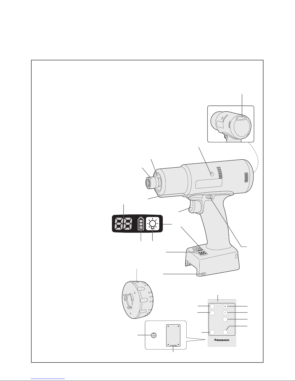
FUNCTIONAL DESCRIPTION
FUNKTIONSBESCHREIBUNG
DESCRIPTION DES FONCTIONS
DESCRIZIONE DELLE FUNZIONI
FUNCTIEBESCHRIJVING
DESCRIPCIÓN FUNCIONAL
FUNKTIONSBESKRIVELSE
FUNKTIONSBESKRIVNING
FUNKSJONSBESKRIVELSE
TOIMINTAKUVAUS
OPIS FUNKCJI
İŞLEVSEL AÇIKLAMA
Remote control, clutch setting handle and battery are not included.
Fernbedienung, Kupplungssteller
und Akku werden nicht mitgeliefert.
La télécommande, la poignée de
réglage de l'embrayage et la batterie
ne sont pas incluses.
Telecomando, manopola per la
frizione e batteria non sono in dotazione.
Afstandsbediening, koppelingafstellingshandgreep en accu zijn niet
inbegrepen.
El control remoto, el ajuste de
embrague y la batería no están
incluidos.
Fjernbetjening, koblingsindstillingsgreb og akku medfølger ikke.
Fjärrkontroll, kopplingsinställningshandtag och batteri medföljer ej.
Fjernkontroll, kløtsjinnstillingshåndtak og batteri er ikke inkludert.
Kaukosäädin, kytkimen asetuskahva
ja paristo eivät kuulu varusteisiin.
Zestaw nie zawiera zdalnego
sterowania, uchwytu do ustawienia
sprzęgła ani akumulatora.
Uzaktan kumanda, kavrama ayarı
kolu ve pil dahil değildir.
(D)
(I)(J)
(K)
(A)
(E)
(F)
(G)
(H)
(L)
(M)
(C)
(B)
EYFA31
A
B
C D
(O)
(P)
(N)
(R)
(U)
(T)
(S)
(W)
(V)
(Q)
(X)

-
3
-
(A)
6.35 mm hex quick connect chuck
6,35-mm-Sechskant-Schnellspannfutter
Mandrin de connexion rapide hexagonal 6,35 mm
Mandrino 6,35 mm per collegamento rapido hex
6,35 mm hex-klauwplaat voor snel aansluiten
Mandril hexagonal de conexión rápida de 6,35 mm
6,35 mm hex hurtigtilslutningspatron
Snabbchuck 6,35 mm sexkantshylsa
6,35 mm hexkjok for rask tilkobling
6,35 mm:n hex-pikaliitinistukka
6,35 mm sześciokątny uchwyt
6,35 mm altıgen hızlı bağlantılı başlık
(B)
Clutch shutter
Kupplungsverschluss
Volet d'embrayage
Coperchio frizione
Koppelingssluiter
Cierre del embrague
Koblingslukker
Kopplingsslutare
Kløtsjlukker
Kytkimen suljin
Przysłona sprzęgła
Kavrama sürgüsü
(C)
Hole for tool hanger
Loch für Werkzeugaufhänger
Trou pour dispositif de suspension de l'outil
Foro per il gancio
Gat voor ophangen van het gereedschap
Oricio para el colgador de la herramienta
Hul til værktøjsophængning
Hål för verktygshängare
Hull for verktøyopphenger
Reikä työkalun pidikkeelle
Otwór do powieszenia narzędzia
Alet askısı deliği
(D)
Tightening conrmation lamp
Anzugsbestätigungslampe
Témoin de conrmation de serrage
Spia conferma serraggio
Bevestigingslampje aanhaaltoestand
Lámpara de conrmación de apriete
Lampe til bekræftelse af stramning
Lampa för bekräftad åtdragning
Strammebekreftelseslampe
Kiristyksen varmistusvalo
Lampka potwierdzenia dokręcenia
Sıkma onay lambası
(E)
Forward/Reverse lever
Rechts-/Linkslauf-Umschalthebel
Levier d’inversion marche avant/marche arrière
Leva di avanzamento/inversione
Vooruit/achteruithendel
Palanca de avance/marcha atrás
Greb til forlæns/baglæns retning
Riktningsomkopplare
Forover-/bakoverspak
Eteenpäin-/taaksepäinvipu
Dźwignia biegu do przodu/wstecznego
İleri/geri kolu
(F)
Alignment mark
Ausrichtmarkierungen
Marques d’alignement
Marcature allineamento
Uitlijnmarkering
Marcas de alineacións
Flugtemærker
Anpassningsmärken
Tilpasningsmerke
Sovitusmerkki
Znak ustawczy
Hizalama işareti
(G)
Remote control receiver
Fernbedienungsempfänger
Récepteur de la télécommande
Ricevitore telecomando
Ontvanger afstandsbediening
Receptor de control remoto
Fjernbetjeningsmodtager
Fjärrstyrningsgivare
Fjernkontrollmottaker
Kaukosäätimen vastaanotin
Odbiornik zdalnego sterowania
Uzaktan kumanda alıcısı
(H)
Control panel
Anzeigefeld
Panneau de commande
Pannello di controllo
Bedieningspaneel
Panel de control
Kontrolpanel
Kontrollpanel
Kontrollpanel
Säätöpaneeli
Panel sterowania
Kontrol paneli
(I)
LED light on/off button
LED-Leuchten-Ein/Aus-Taste
Bouton Marche/Arrêt de la lumière DEL
Tasto di accensione e spegnimento della luce LED
Aan/uit-toets LED-lampje
Botón encendido/apagado de luz LED
Tænd/sluk-knap til LED-lys
Strömbrytare för LED-ljus
LED-lys på/av-knapp
LED-valon kytkin/katkaisupainike
Przycisk włączania/wyłączania diody LED
LED ışık açma/kapama düğmesi
(J)
Battery indication lamp
Akku-Anzeigelampe
Témoin indicateur de la batterie
Spia livello batteria
Accu-indicatielampje
Lámpara de indicadora de la batería
Akku-indikatorlampe
Batteriindikator
Batteriindikasjonslampe
Akun merkkivalo
Wskaźnik poziomu mocy akumulatora
Pil gösterge lambası

-
4
-
(K)
Display
Anzeige
Afchage
Display
Display
Visor
Display
Indikeringsfönster
Display
Näyttö
Wyświetlacz
Ekran
(L)
Variable speed control trigger
Elektronikschalter mit variabler Drehzahlregelung
Gâchette de commande de vitesse
Grilletto di controllo velocità variabile
Variabele snelheidregelingsschakelaar
Disparador del control de velocidad variable
Kontroludløser for variabel hastighed
Avtryckare med variabel varvtalsreglering
Trinnløs hovedbryter
Nopeudensäätökytkin
Zapadka kontroli prędkości obrotowej
Değişken hız kontrol tetiği
(M)
LED light
LED-Leuchte
Lumière DEL
Luce LED
LED-lampje
Luz LED
LED-lys
LED-ljus
LED-lys
LED-valo
Dioda LED
LED ışık
(N)
Remote control
Fernbedienung
Télécommande
Telecomando
Afstandsbediening
Control remoto
Fjernbetjening
Fjärrkontroll
Fjernkontroll
Kaukosäädin
Zdalne sterowanie
Uzaktan kumanda
(O)
+ button
Taste +
Bouton +
Tasto +
+-toets
Botón +
+ knap
Knapp +
+ knapp
+ painike
Przycisk +
+ düğmesi
(P)
− button
Taste −
Bouton −
Tasto −
−-toets
Botón −
− knap
Knapp −
− knapp
− painike
Przycisk −
− düğmesi
(Q)
OK button
Taste OK
Bouton OK
Tasto OK
OK-toets
Botón OK
OK-knap
Bekräftelseknapp
OK-knapp
OK-painike
Przycisk OK
Tamam düğmesi
(R)
D button
Taste D
Bouton D
Tasto D
D-toets
Botón D
D-knap
D-knapp
D-knapp
D-painike
Przycisk D
D düğmesi
(S)
C button
Taste C
Bouton C
Tasto C
C-toets
Botón C
C-knap
C-knapp
C-knapp
C-painike
Przycisk C
C düğmesi
(T)
B button
Taste B
Bouton B
Tasto B
B-toets
Botón B
B-knap
B-knapp
B-knapp
B-painike
Przycisk B
B düğmesi

-
5
-
(U)
A button
Taste A
Bouton A
Tasto A
A-toets
Botón A
A-knap
A-knapp
A-knapp
A-painike
Przycisk A
A düğmesi
(V)
Holder
Halter
Support
Supporto
Houder
Retenedor
Holder
Hållare
Holder
Pidin
Uchwyt
Tutucu
(W)
Battery
Akku
Batterie
Batteria
Accu
Batería
Akku
Batteri
Batteri
Akku
Akumulator
Pil
(X)
Clutch setting handle
Kupplungssteller
Poignée de réglage de l'embrayage
Manopola per l'impostazione della frizione
Koppelinginstellingshandgreep
Empuñadura de ajuste de embrague
Koblingsindstillingsgreb
Kopplingsinställningshandtag
Kløtsjinnstillingshåndtak
Kytkimen asetuskahva
Uchwyt ustawiania sprzęgła
Kavrama ayarı kolu
-
6
-
Illustrations/Abbildungen/Illustrations/Illustrazioni/Afbeeldingen/Imágenes/
Illustrationer/Illustrationer/Illustrasjoner/Kuvat/Ilustracje/Resimler
1 2 3 4
Approx. 50 cm
A
p
p
r
o
x
.
6
0
°
A
p
p
r
o
x
.
6
0
°
5
8
9
7
Control Panel
Anzeigefeld
Panneau de
commande
Pannello di
controllo
Bedieningspaneel
Panel de control
Kontrolpanel
Kontrollpanel
Kontrollpanel
Säätöpaneeli
Panel sterowania
Kontrol paneli
Approx. 50 cm
ca. 50 cm
Environ 50 cm
Circa 50 cm
Ongeveer 50 cm
Aprox. 50 cm
Ca. 50 cm
Ca 50 cm
Ca. 50 cm
Noin 50 cm
Ok. 50 cm
Yaklaşık 50 cm
Approx. 60°
ca. 60°
Environ 60°
Circa 60°
Ongeveer 60°
Aprox. 60°
Ca. 60°
Ca 60°
Ca. 60°
Noin 60°
Ok. 60°
Yaklaşık 60°
Battery indication lamp
Akku-Anzeigelampe
Témoin indicateur de la
batterie
Spia livello batteria
Accu-indicatielampje
Lámpara de indicadora
de la batería
Akku-indikatorlampe
Batteriindikator
Batteriindikasjonslampe
Akun merkkivalo
Wskaźnik poziomu
mocy akumulatora
Pil gösterge lambası
LED light on/off button
LED-Leuchten-Ein/Aus-
Taste
Bouton Marche/Arrêt de la
lumière DEL
Tasto di accensione e
spegnimento della luce
LED
Aan/uit-toets LED-lampje
Botón encendido/apagado
de luz LED
Tænd/sluk-knap til LED-
lys
Strömbrytare för LED-ljus
LED-lys på/av-knapp
LED-valon kytkin/
katkaisupainike
Przycisk włączania/
wyłączania diody LED
LED ışık açma/kapama
düğmesi
6
-
7
-
0
2
4
6
8
10
12
#1 #10 #30#20 #40 #50 #60
N m
EYFGA3
EYFGA2
EYFGA1
10
11 12
13
Torque setting level
Torque setting level
Drehmoment-Einstellungsstufe
Niveau de réglage du couple
Livello impostazione coppia
Instellingsniveau
aanhaalmoment
Nivel de ajuste del par de
torsión
Momentindstillingsniveau
Momentinställningsnivå
Momentinnstillingsnivå
Kiristysmomentin asetustaso
Ustawienie poziomu momentu
obrotowego
Tork ayar seviyesi
#20
#40
(1)
(2)
-
8
-
14
17
16
15
EYFA31
A
B
C D
Display
Anzeige
Afchage
Display
Display
Visor
Display
Indikeringsfönster
Display
Näyttö
Wyświetlacz
Ekran
Battery indication lamp
Akku-Anzeigelampe
Témoin indicateur de la batterie
Spia livello batteria
Accu-indicatielampje
Lámpara de indicadora de la batería
Akku-indikatorlampe
Batteriindikator
Batteriindikasjonslampe
Akun merkkivalo
Wskaźnik poziomu mocy akumulatora
Pil gösterge lambası
Control Panel
Anzeigefeld
Panneau de
commande
Pannello di
controllo
Bedieningspaneel
Panel de control
Kontrolpanel
Kontrollpanel
Kontrollpanel
Säätöpaneeli
Panel sterowania
Kontrol paneli
OK button
Taste OK
Bouton OK
Tasto OK
OK-toets
Botón OK
OK-knap
Bekräftelseknapp
OK-knapp
OK-painike
Przycisk OK
Tamam düğmesi
-
9 -
I
. INTENDED USE
This tool is a Cordless Screwdriver and can
be used to tighten bolts, nuts, and screws with
torque control. Additionally, the tool with the radio transmitter option can transmit an OK/NOK
signal to the Assembly Qualiers.
IMPROPER USE
The use of the tool other than INTENDED USE
is dangerous and must be avoided.
The tool must not be used for the purposes
such as the following;
• to mix paint or building materials,
• polishing, grinding, sharpening, engraving.
RESIDUAL RISK
Some residual risks remains even with proper
use of the tool such as the following;
• contact with the rotating bit
• contact with the sharp edges of material or
something.
Read “the Safety Instructions” booklet
and the following before use.
II
.
ADDITIONAL SAFETY
RULES
1
) Wear ear protectors when using the
tool for extended periods.
2) Be aware that this tool is always in an
operating condition, since it does not have
to be plugged into an electrical outlet.
3) Hold power tools by insulated gripping
surfaces when performing an operation
where the cutting tool may contact hidden wiring or its own cord.
Contact with a “live” wire will make exposed
metal parts of the tool “live” and shock the
operator.
4) Do NOT operate the Forward/Reverse
lever when the main switch is on. The battery will discharge rapidly and damage to
the unit may occur.
5) During charging, the charger may become
slightly warm. This is normal.
Do NOT charge the battery for a long period.
6) When storing or carrying the tool, set the
Forward/Reverse lever to the center position (switch lock).
7) Do not strain the tool by holding the speed
control trigger halfway (speed control
mode) so that the motor stops.
Symbol Meaning
V
Volts
Direct current
n
0
No load speed
… min
-1
Revolutions or
reciprocations per minutes
Ah
Electrical capacity of battery
pack
To reduce the risk of
injury, user must read and
understand instruction
manual.
Do not incinerate or heat
battery pack. Do not charge
or use under conditions of
high temperature. Do not ex-
pose to high temperatures.
Do not disassemble or
modify.
Do not expose to rain or
water.
III
. ASSEMBLY
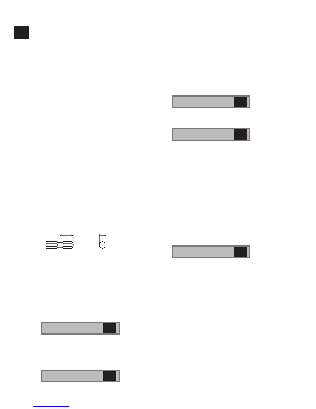
Attaching or Removing Bit
NOTE:
•
When attaching or removing a bit, disconnect battery pack from tool or place the
switch in the center position (switch lock).
1. Hold the collar of quick connect chuck and
pull it out from the tool.
2. Insert the bit into the chuck. Release the
collar.
3. The collar will return to its original position
when it is released.
4.
Pull the bit to make sure it does not come out.
5. To remove the bit, pull out the collar in the
same way.
-
10 -
EN EN
CAUTION:
• If the collar does not return to its origi
nal position or the bit comes out when
pulled on, the bit has not been properly
attached. Make sure the bit is properly
attached before use.
9 mm – 9.5 mm 6.35 mm
Attaching or Removing Battery Pack
1. To connect the battery pack:
Align the highlighted marker points and
attach battery pack.
• Slide the battery pack until it locks into
position.
See the illustration
1
2. To remove the battery pack:
• Push down the highlighted button and
slide the battery pack forward.
See the illustration
2
IV
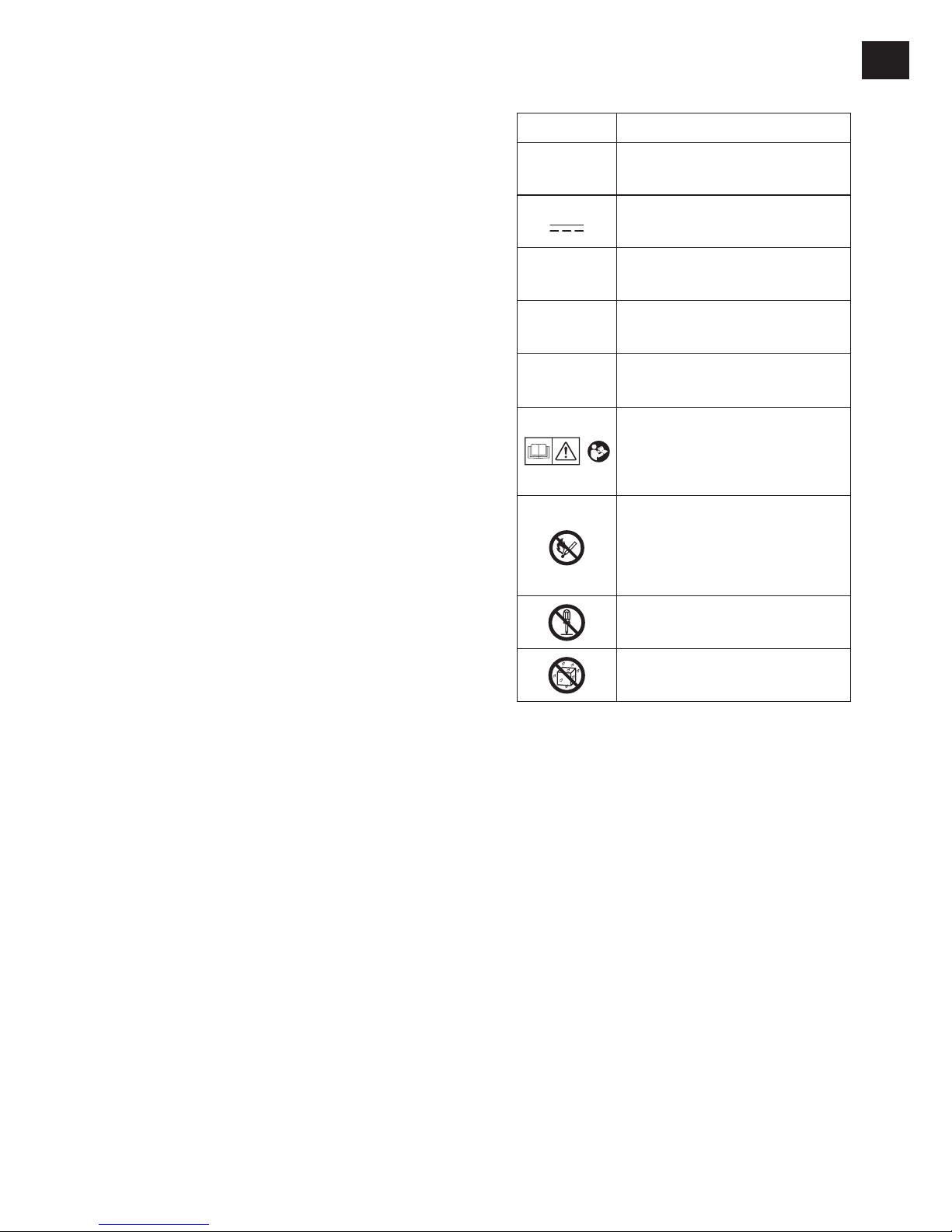
. OPERATION
Before Using the Remote
Control (Available as an
optional accessory)
Insert the battery
1. Pull out the battery holder.
1 Push in on the fastener as indicated by the
arrow.
2 Pull out the holder.
See the illustration
3
2. Insert the battery and push the holder
back in.
See the illustration
4
NOTE:
•
If the tool does not respond to the wireless remote control even when the remote
control is operated close to the tool, the
battery (CR2025) is dead. Replace it with
a new battery.
• The included battery is provided for sample use and may not last as long as commercially available batteries.
Wireless remote control range
See the illustration
5
The remote control should be operated within
approximately 50 cm and approximately 60°
vertically and horizontally of the perpendicular
relative to the infrared receiver on the tool.
• Under the following circumstances, you may
not be able to operate the tool, even within
this range.
• When an object between the remote con
-
trol’s transmitter and the tool’s receiver.
• When the remote control’s transmitter has
been exposed to light.
• When the remote control’s transmitter or
tool’s receiver are dirty.
[Main Body]
CAUTION:
•
If a tool holder is used with the
Panasonic EYF series assembly tools,
make sure the tool’s trigger switch
doesn’t hit the tool holder. It may run the
tool accidentally and result in battery
failure by unexpected battery discharge.
See the illustration
6
Forward / Reverse Rotation
Switch operation
See the illustration
7
1. Push the lever for forward or reverse
rotation. Check the direction of the lever
before using.
2. Depress the trigger switch slightly to start
the tool slowly.
3. Speed will increase by pressing the trig
ger. The tool stops working immediately
by releasing the trigger.
4. When done with an application, lock the
switch by centering the lever.
CAUTION:
• To prevent damage, do not use the for
-
ward/reverse lever when tool is in use.
-
11 -
• In order to prevent excessive increased
in temperature, do not operate the tool
continuously without interval after finishing a battery.
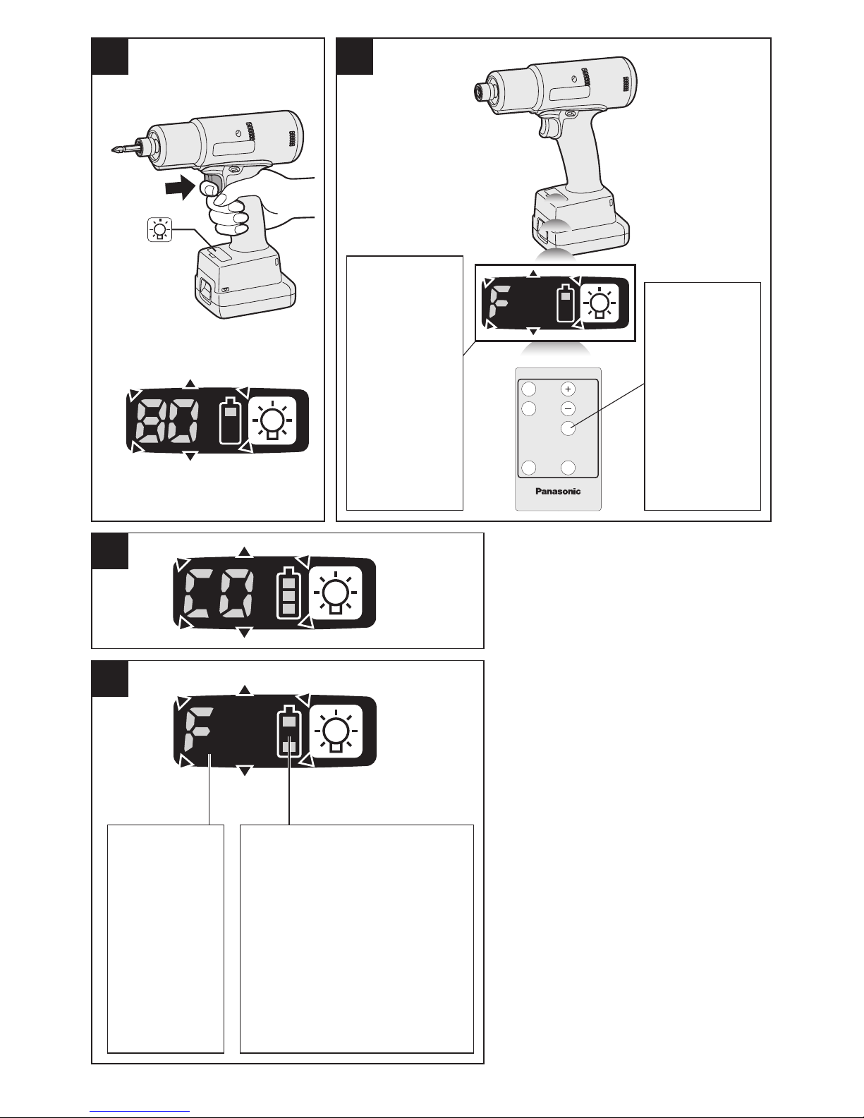
Tightening confirmation lamp
• The tightening confirmation lamp can be
used to check whether tightening has been
completed properly.
See the illustration
8
Tool status Lamp display
Tightening complete
(Normal clutch operation)
Green
(For approx. 2
seconds)
• Tightening not complete
• Tightening complete
without fullling the set
function conditions
Red
(For approx. 2
seconds)
The automatic poweroff function has been
activated.
Red
(For approx. 5
minutes)
NOTE
• The tightening configuration lamp will
not turn on in reverse rotation mode.
• The tightening configuration lamp turns
off when the tool restarts an application.
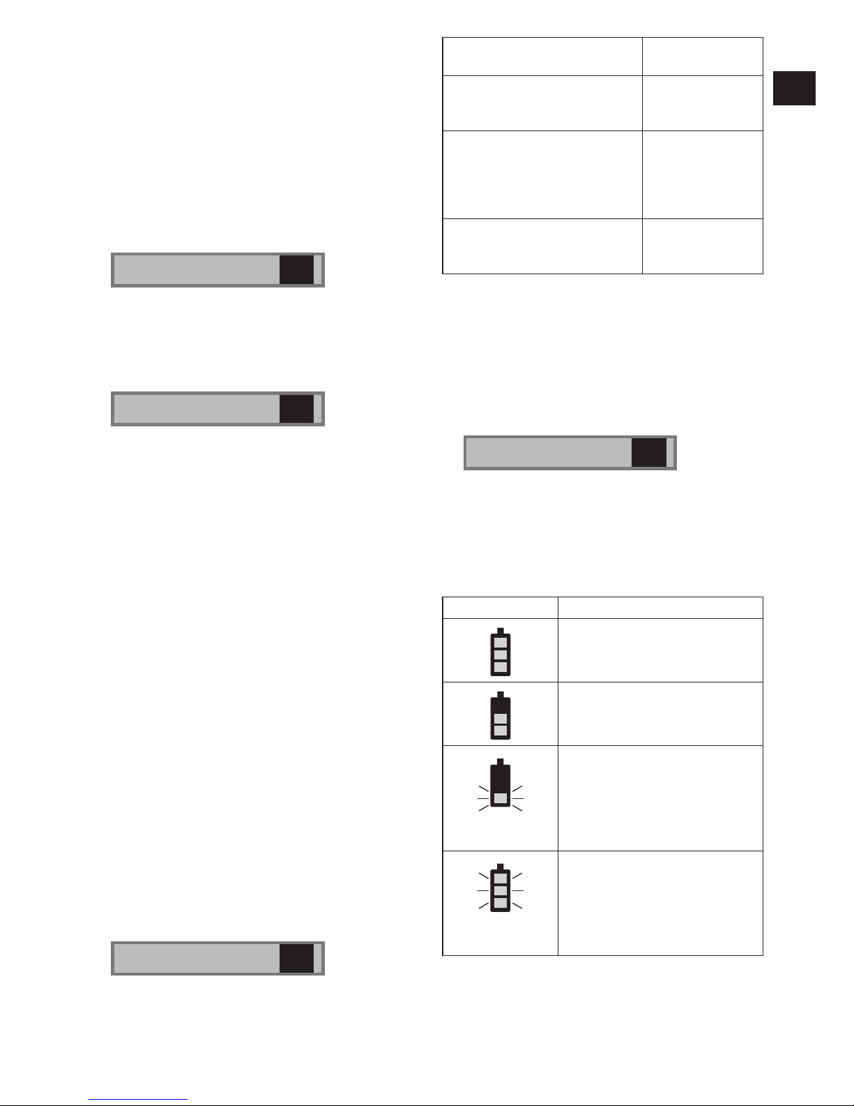
The battery indication lamp
See the illustration
9
• The battery indication lamp notifies user on
remaining battery power.
• Battery life varies slightly with ambient tem
-
perature and battery characteristics.
Indicator Battery status
Fully charged
Approx. 40% or less
remaining
Flashing
Flashing
Approx. 20% or less
remaining (indicates need
to recharge battery)
The battery pack will need
to be charged soon.
Flashing
No charge
The battery pack needs to
be charged.
(The tool’s automatic
power-off function will
activate at this stage.)
Automatic power-off function
• The automatic power-off function is designed
to prevent a loss of tightening torque due to
reduced battery voltage. Once it has been
activated, the tool will not operate until the
battery pack has been charged (or replaced
with a fresh unit), even if the trigger is
depressed.
NOTE:
• All 3 bars on the battery indication lamp
will flash when the automatic power-off
function is activated.
•
Be sure that the battery pack is fully
charged, otherwise the automatic poweroff function may not activate properly.
• The tool may power off automatically
under heavy work loads.
However the tool will be operational
again after the battery is removed and
reinstalled. The battery must have a
sufficient charge to re-enable the tool.
LED light
See the illustration
9
Press the button to turn on/off the LED
light.
NOTE:
• The light consumes very little power
and will not significantly affect battery
run time.
• The built-in LED light is designed for
temporary use, and may have less
brightness than a regular traditional
flashlight.
• LED light can be linked to trigger switch
operation by setting with a remote control. (See page 14.)
Caution: DO NOT STARE INTO BEAM.
Use of controls or adjustments or performance
of procedures other than those specied herein
may result in hazardous radiation exposure.
-
12 -
EN EN
Tightening Torque Setting
See the illustration
10
1.
Open the shutter, (1) in the illustration 10,
with the clutch setting handle, (2) in the illus
-
tration 10.
Engage the ribs on the main unit with the
ribs on the clutch setting handle (on the
short side) and turn clockwise.
See the illustration
11
2. Insert the 3 ribs on clutch setting handle
(on the long side) into the shutter holes.
User should insert the highlighted wider
rib into the highlighted hole.
To increase clutch torque, turn the clutch
setting handle clockwise. To decrease
clutch torque, turn the clutch setting handle counterclockwise.
See the illustration
12
3. Close the shutter with the clutch setting
handle (on the short side) by turning counterclockwise.
NOTE
• Be sure to close the shutter after setting
has been completed in order to prevent
dust from entering.
• Illustration
12
is an example of clutch
the getting at #20 and #40.
Tightening torque chart (reference
values)
See the illustration
13
• Refer to the tightening torque chart, in illustration 13, to select torque settings.
• The values in the chart are just for reference
and measured under the conditions defined
by Panasonic. During actual work, values
will vary based on operating conditions.
Measurement conditions
As dened by Panasonic
CAUTION:
• Do not use the tool without prior verifi
cation of its tightening torque setting to
avoid excessive or inadequate torque.
•
Always finish rundown with the tool’s trigger switch fully depressed. Otherwise, it
may affect torque accuracy.
Configuring Tool Settings
RPM adjustment setting
1. Turn off the control panel.
• If the control panel is on, remove and
then reinsert the battery pack.
2. Depress the switch while pushing the
button and then release both the button and the switch.
• After the LED light and tightening con
firmation lamp have illuminated and the
buzzer has rung, the control panel will
flash and change to configuration mode.
See the illustration
14
NOTE:
• The control panel will turn off if the tool
is not operated for a period of 5 minutes.
See the illustration
15
3. Press the and buttons to select the
clutch setting that is appropriate for the
work being performed.
17…77
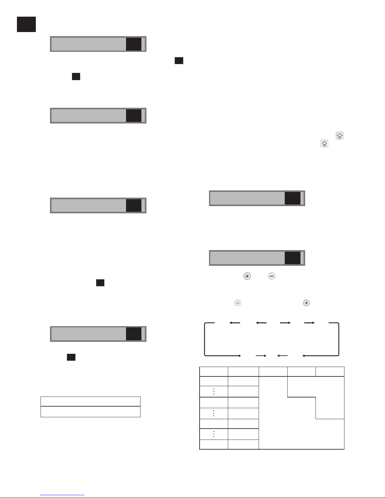
158079 1678
As the button
is pressed
As the button
is pressed
RPM GA1 GA2 GA3
80 800
Setting not
available
75 750
45 450
Setting
available
15 150
-
13 -
4. Press the OK button to accept the new
setting.
• The control panel will stop flashing and
light up.
CAUTION:
• You must press the OK button in order
for the selected setting to take effect.
• Be sure to verify the new value after
changing the setting. (See page 15.)
Auto downshift function
• In this function, the tool starts with high
speed tightening operation and then
automatically shifts to a lower speed, 300
RPM, at the timing pre-programmed by user.
This function increases the efficiency while
not damaging materials.
1. Set the tool to setting configuration mode.
(See page 12.)
2. Press the D button twice.
• The auto downshift function setting value
will be displayed.
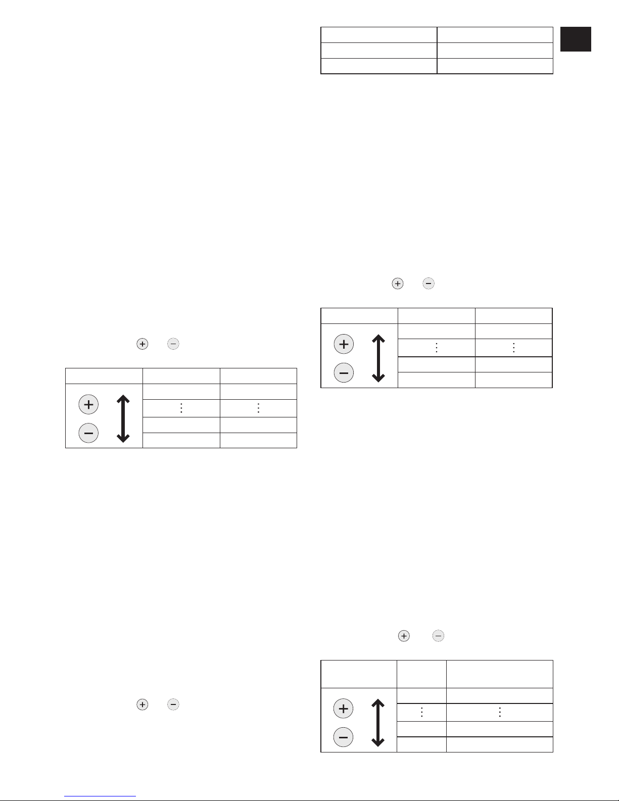
3. Press the
or buttons to change the
time as desired.
Operation Display Seconds
30 3 seconds
1 0.1 seconds
0 OFF
4. Press the OK button to accept the new
setting.
NOTE:
• The speed at the start of tightening
operation is set with the speed adjustment function.
Cross thread reduction function
• The tool runs in reverse approximately
360° before running forward to assist in
the alignment of the threads to help reduce
cross threads.
1. Set the tool to setting configuration mode.
(See page 12.)
2. Press the D button once.
• The cross thread reduction function set
-
ting value will be displayed.
3. Press the
or buttons to change the
setting to ON or OFF.
Display Function
R0 OFF
R1 ON
4. Press the OK button to accept the ON or
OFF setting.
Rundown error detecting function
• In this function alerts the users that if
tightening has ended in less time than the
pre-set time by user. This function can be
used to find out rundown errors such as
retightening and cross thread.
1. Set the tool to setting configuration mode.
(See page 12.)
2. Press the B button twice.
• The rundown error detecting function
setting value will be displayed.
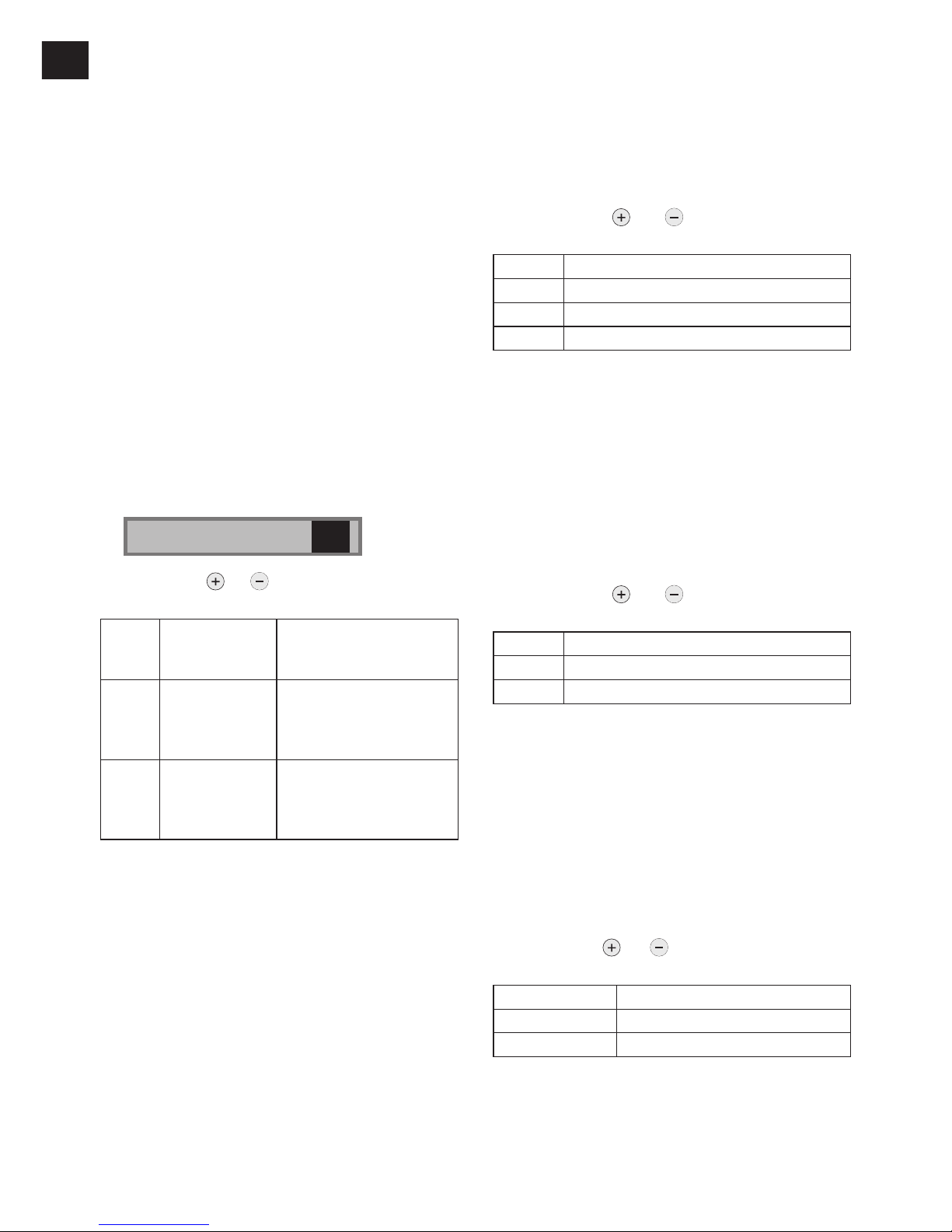
3. Press the
or buttons to change the
time as desired.
Operation Display Seconds
30 3 seconds
1 0.1 seconds
0 OFF
4. Press the OK button to accept the new
setting.
• When the cross thread reduction func
tion is ON, the set time will be counted
after the tool operates in reverse for
approximately 360°.
Maintenance interval alarm function
• In this function, the tool is locked once a set
number of tightening operations has been
programmed. This function can be used
to know the regular inspection timing, for
example.
1. Set the tool to setting configuration mode.
(See page 12.)
2. Press the C button twice.
• The setting value will be displayed.
3. Press the
or buttons to set the
desired value.
Operation Display
Number of tightening
operations
99 990,000
1 10,000
0 OFF
-
14 -
EN EN
4. Press the OK button to accept the new
setting.
NOTE:
• When the remaining number of tighten
ing operations is 10,000 or less, the
display will alternate between “Setting”
and “1.” When the remaining number
of tightening operations reaches 0, the
value “0” will flash on the display.
To reset the count to 0, initialize the tool
(see page 15).
• The maximum tightening operation
count value is 990,000. Operations in
excess of 990,000 will not be counted.
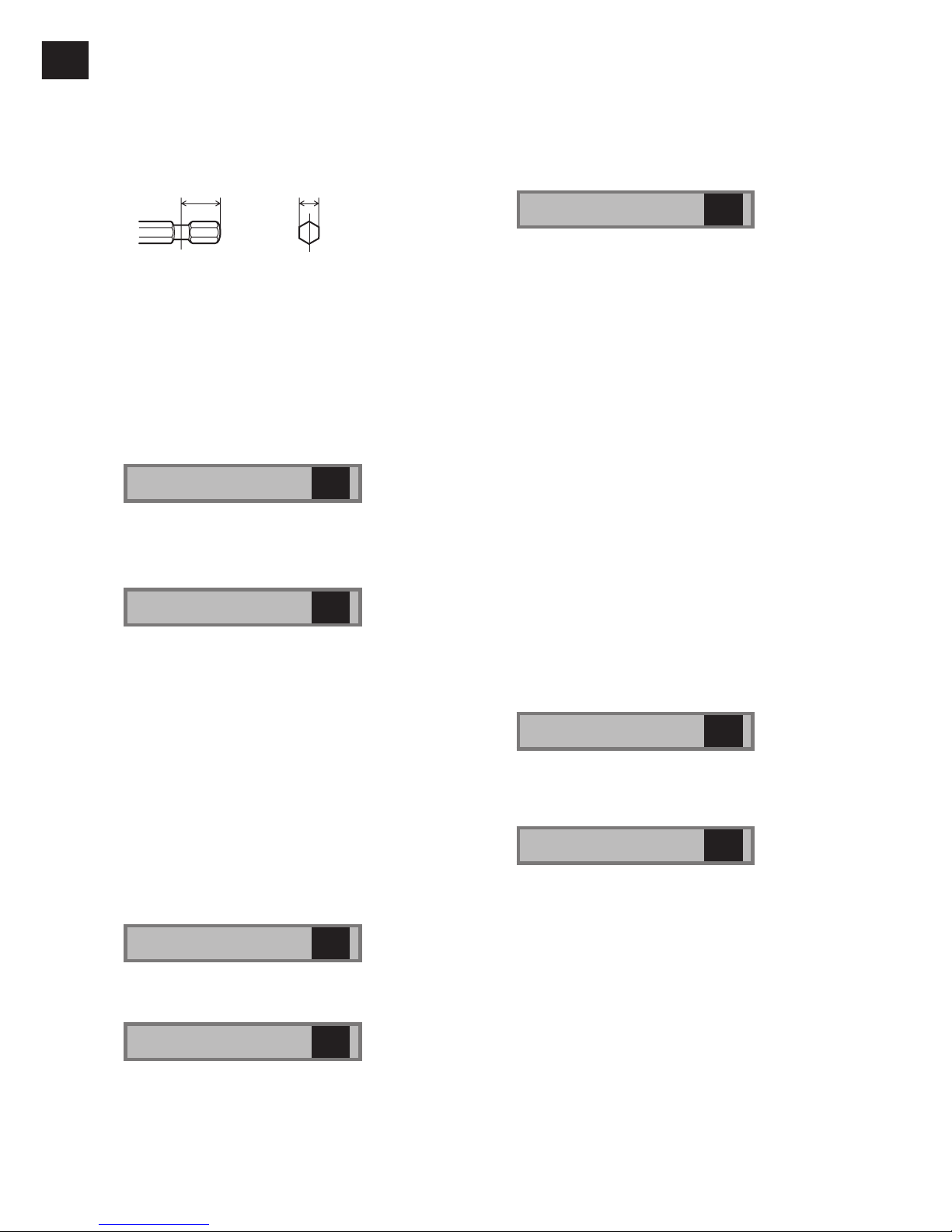
Radio signal range limitation function
on/off setting (EYFGA1AR, EYFGA2AR,
EYFGA3AR)
1. Set the tool to setting configuration mode.
(See page 12.)
2. Press the C button three times.
• Radio signal range limitation function
on/off setting value will be displayed.
See the illustration
16
3. Press the or buttons to set radio signal range limitation function on/off.
Display
Radio signal
range limitation
function mode
Status
C0 OFF
Tool is operational in the
absence of communications with the Assembly
Qualier.
C1 ON
Tool is not operational
in the absence of communications with the As-
sembly Qualier.
4. Press the OK button to accept the new
setting.
NOTE:
• For more information about how to register
the tool and Assembly Qualifier, see the
Assembly Qualifier instruction manual.
Buzzer setting
• You can select from three buzzer modes.
1. Set the tool to setting configuration mode.
(See page 12.)
2. Press the A button once.
• The current setting value will be dis
-
played.
3. Press the
or buttons to set the
desired value.
Display Function
b0 No buzzer
b1
Buzzer accompanying green indicator
b2 Buzzer accompanying red indicator
4. Press the OK button to accept the new
setting.
LED light setting
• You can select from two LED light modes.
1. Set the tool to setting configuration mode.
(See page 12.)
2. Press the B button once.
• The current setting value will be dis
-
played.
3. Press the
or buttons to set the
desired LED mode.
Display Function
L1 Linked to LED light button
L2
Linked to trigger switch operation
4. Press the OK button to accept the new
setting.
Speed control function
• The speed (RPM) can be changed with the
amount of depression of the trigger.
1. Set the tool to setting configuration mode.
(See page 12.)
2. Press the B button three times.
• The setting value will be displayed.
3. Press the
or buttons to change the
setting to ON or OFF.
Operation Function
P0 Speed control ON
P1 Speed control OFF
4.
Press the OK button to accept the new setting.
-
15 -
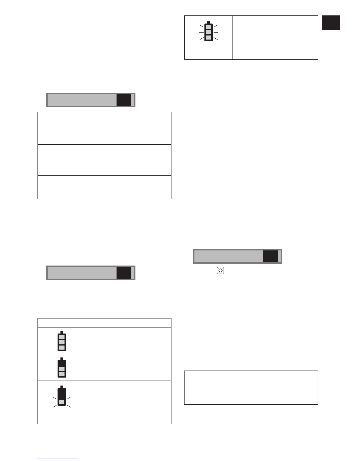
Initializing all settings
• This section explains how to revert all tool
settings to their default values at the time of
shipment from the factory.
• The error display will be turned off.
1. Set the tool to setting configuration mode.
(See page 12.)
2. Press the C button.
• The control panel will begin flashing.
Display: The letter “F” ashes on and off.
Battery indication lamp: The upper and
lower bars of the battery ash on and off.
See the illustration
17
3. Press the OK button to accept the select-
ed setting.
• The control panel will stop flashing and
light up.
Default settings (Original/Factory settings)
• Speed adjustment function
→ GA1: 80 GA2: 75 GA3: 45
• Auto downshift function → 0
• Cross thread reduction function → R0
• Rundown error detecting function → 0
• Maintenance interval alarm function
→ 0
• Radio signal range limitation function
→ C0
• Buzzer setting → b0
• LED light setting → L1
• Speed control setting → P0
Checking tool settings
• When the tool stops, the current setting
value will be displayed for approximately 2
seconds.
• The setting status cannot be checked while
the tool panel is off. Depress the trigger
switch once to turn on the panel.
Checking the status of the speed
adjustment and buzzer settings
1. Press the A button.
• The RPM and buzzer setting values will
be displayed (in that order).
Example: If the RPM is set to 500 min
-1
and the buzzer is set to sound at the
green indicator,
“50” → “b1”
Checking the status of the LED light
and rundown error detecting function and speed control function settings
1. Press the B button.
• The LED light and tightening time and
speed control setting will be displayed
(in that order).
Example: If the LED light mode is set to
L1 and the tightening time is set to 20
and speed control is set to ON,
“L1” → “20” → P0
Checking the status of the radio signal range limitation function and
maintenance interval alarm function
settings
1. Press the C button.
• The range limitation function and num
ber of tightening operations settings
will be displayed along with the current
count value (in that order).
NOTE:
• If you depress the switch while a setting
is being displayed, the control panel will
revert to the speed adjustment setting
display.
Checking the tool circuits and the
status of the cross thread reduction
function and auto downshift function settings
1. Press the D button.
• The tool circuits and cross thread reduc
tion function and auto downshift function
settings will be displayed (in that order).
Example: “H3” → “R1” → “10”
Display Tool circuit
H1 EYFGA1
H2 EYFGA2
H3 EYFGA3
NOTE:
• When other tools are in the area which
are not set, they may accidentally
receive a signal when setting the tool
by remote control.
Set the tool in another room if possible
or keep a fair distance to avoid this situation.
-
16 -
EN EN
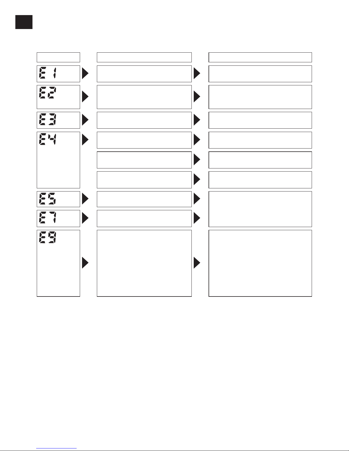
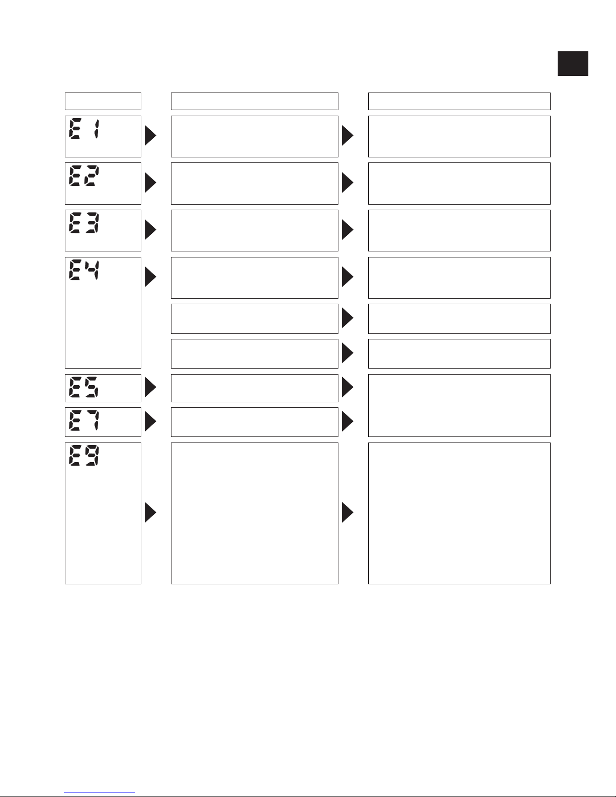
Error Display
In the event of a tool or battery pack malfunction, the control panel will display an error message.
Please check the tool or battery pack as described in the following chart before having them
serviced.
Display Likely cause Corrective action
Setting error Re-initialize the tool using the
remote control. (See page 15.)
The battery pack is too hot. Stop work and allow the battery
pack to cool before resuming use
of the tool.
The tool is too hot to operate. Stop work and allow the tool to
cool before resuming use.
The contacts that connect the
battery pack and tool are dirty.
Remove any dirt.
The battery pack has not been
properly inserted into the tool.
Insert the battery pack rmly into
the tool.
The pins on either the tool or
battery pack have worn down.
Replace the battery pack.
Motor failure, etc. Stop using the tool immediately.
Tool circuit malfunction, failure,
etc.
The tool is unable to communicate with the Assembly Quali-
er while the radio signal range
limitation function is on.
• Verify that the tool has been
properly registered to the Assembly Qualifier.
•
Verify that the Assembly Qualifier’s group setting has been configured correctly.
•
Improve the reception state, for
example by moving the Assembly Qualifier closer to the tool.
-
17 -
[Battery Pack]
For appropriate use of Liion battery pack
• For optimum battery life, store the Li-ion battery pack following use without charging it.
• When charging the battery pack, confirm
that the terminals on the battery charger
are free of foreign substances such as dust
and water etc. Clean the terminals before
charging the battery pack if any foreign substances are found on the terminals.
The life of the battery pack terminals may be
affected by foreign substances such as dust
and water etc. during operation.
• When battery pack is not in use, keep it
away from other metal objects like: paper
clips, coins, keys, nails, screws, or other
small metal objects that can make a connection from one terminal to another.
Shorting the battery terminals together may
cause sparks, burns or a fire.
•
When operating the battery pack, make sure
the work place is well ventilated.
•
When the battery pack is removed from the
main body of the tool, replace the battery
pack cover immediately in order to prevent
dust or dirt from contaminating the battery
terminals and causing a short circuit.
Battery pack life and recycling
The rechargeable batteries have a limited life.
If the operation time becomes extremely short
after recharging, replace the battery pack with
a new one.
For environmental protection and recycling of
materials, be sure that it is disposed of at an
ofcially assigned location, if there is one in
your country.
[Battery Charger]
The recommended charg-
ing process
Read the operating manual for Panasonic battery charger for the battery pack before charging.
Charge the battery at a temperature of 5°C to
40°C.
The battery pack cannot be charged at a
temperature of less than 5°C. If the temperature
of the battery pack is less than 5°C, keep the
battery pack for an hour in a location where
the temperature is 5°C or warmer before
charging.
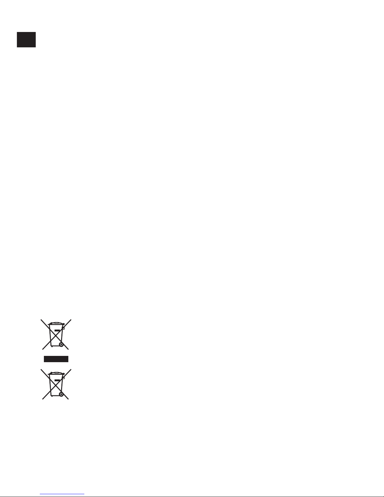
Information for Users on Collection and Disposal of Old Equip-
ment and used Batteries
These symbols on the products, packaging, and/or accompanying documents mean
that used electrical and electronic products and batteries should not be mixed with
general household waste.
For proper treatment, recovery and recycling of old products and used batteries, please
take them to applicable collection points, in accordance with your national legislation
and the Directives 2012/19/EC and 2006/66/EC.
By disposing of these products and batteries correctly, you will help to save valuable
resources and prevent any potential negative effects on human health and the
environment which could otherwise arise from inappropriate waste handling.
For more information about collection and recycling of old products and batteries,
please contact your local municipality, your waste disposal service or the point of sale
where you purchased the items.
Penalties may be applicable for incorrect disposal of this waste, in accordance with
national legislation.
For business users in the European Union
If you wish to discard electrical and electronic equipment, please contact your dealer or
supplier for further information.
-
18 -
EN EN
[Information on Disposal outside the European Union]
These symbols are only valid in the European Union. If you wish to discard these items,
please contact your local authorities or dealer and ask for the correct method of disposal.
V.
SPECIFICATIONS
NOTE:
Weight indication
Greater than or equal to 1kg : indicated by 0.05kg.
Less than 1kg : indicated by 0.01kg.
MAIN UNIT
Model
EYFGA1 EYFGA2 EYFGA3
A AR A AR A AR
Motor 14.4 V DC
Chuck size
Single-ended 9-9.5 mm
Double-ended 12 mm
No load speed (Stage) 0-800 (80) 0-750 (75) 0-450 (45)
Torque adjustment range
2-5.5 N·m
(0.20-0.56 kgf·m)
5-8 N·m
(0.51-0.82 kgf·m)
5-10 N·m
(0.51-1.02 kgf·m)
Number of torque setting levels60(In approx. 0.08 N·m
increments)
60
(In approx. 0.08 N·m
increments)
60
(In approx. 0.13 N·m
increments)
Overall length 199 mm
Weight (with battery pack: EYFB41)
1.25 kg 1.3 kg
Weight (with battery pack: EYFB42)
1.5 kg 1.5 kg
CAUTION:
Always check the tool’s tightening torque before use.
Improper tool operation may result in excessive or inadequate tightening.
NOTE:
Number of torque setting levels
Though the torque setting level of clutch handle may exceed 60 levels, please set the level up
to 60 levels.
BATTERY PACK (not included with shipment)
Model EYFB41 EYFB42
Storage battery Li-ion battery
Battery voltage 14.4 V DC (3.6 V/4 cells) 14.4 V DC (3.6 V/8 cells)
BATTERY CHARGER (not included with shipment)
Model EY0L82
Rating See the rating plate on the bottom of the charger.
Weight 0.93 kg
Charging time
EYFB41
Usable: 35 min.
Full: 40 min.
EYFB42
Usable: 50 min.
Full: 60 min.

-
19 -
Remote control (not included with shipment)
Model EYFA31
Battery voltage 3 V DC
Dimensions 54 mm × 86 mm × 10 mm
Weight (with battery) Approximately 30 g
Assembly Qualifier (not included with shipment)
Model EYFR02
Rating See the rating plate on the bottom of the Assembly Qualier.
Dimensions 120 mm × 260 mm × 70 mm
Weight 1.1 kg
Radio Information
Indoor/Urban Range 100 ft./30 m
Outdoor RF line-of-sight range 300 ft./100 m
Transmit Power 1 mW (0 dBm)
Assembly Qualier Sensitivity -92 dBm (1% packet error)
Channel Frequencies:
Channel 1 2.410 GHz Channel 5 2.430 GHz Channel 9 2.450 GHz
Channel 2 2.415 GHz
Channel 6 2.435 GHz Channel 10 2.455 GHz
Channel 3 2.420 GHz Channel 7 2.440 GHz Channel 11 2.460 GHz
Channel 4 2.425 GHz Channel 8 2.445 GHz Channel 12 2.465 GHz
VI.
MAINTENANCE
Use only a dry, soft cloth for wiping the unit. Do not use a damp cloth, thinner, benzine, or other
volatile solvents for cleaning.
VII
. ACCESSORIES
Charger
• EY0L82
Battery pack
• EYFB41
• EYFB42
Remote control
• EYFA31
Protector for tool
• EYFA05-A (Blue)
• EYFA05-Y (Yellow)
• EYFA05-H (Gray)
Protector for battery
• EYFA04-H
• EYFA06-H
Assembly Qualier
• EYFR02
Clutch setting handle
• EYFA32
Tool hanger
• EYFA40
CAUTION:
Tool hanger is for balancer use only.
Excessive force or impact might break it and
the main unit might fall off.
-
20 -
EN EN
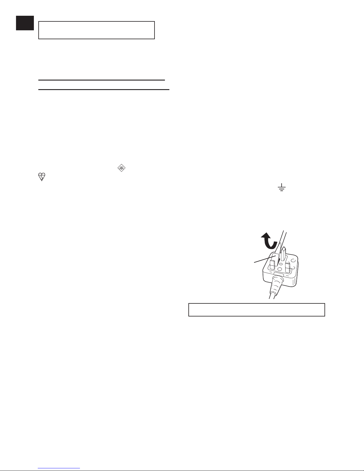
ONLY FOR U. K.
VIII
.
ELECTRICAL PLUG
INFORMATION
FOR YOUR SAFETY PLEASE READ
THE FOLLOWING TEXT CAREFULLY
This appliance is supplied with a moulded
three pin mains plug for your safety and
convenience.
A 5 amp fuse is tted in this plug.
Should the fuse need to be replaced please
ensure that the replacement fuse has a rating of 5 amp and that it is approved by ASTA
or BSI to BS1362.
Check for the ASTA mark or the BSI mark
on the body of the fuse.
If the plug contains a removable fuse cover
you must ensure that it is retted when the
fuse is replaced.
If you lose the fuse cover the plug must not
be used until a replacement cover is obtained.
A replacement fuse cover can be purchased
from your local Panasonic Dealer.
IF THE FITTED MOULDED PLUG IS UNSUITABLE FOR THE SOCKET OUTLET IN
YOUR HOME THEN THE FUSE SHOULD
BE REMOVED AND THE PLUG CUT OFF
AND DISPOSED OF SAFELY.
THERE IS A DANGER OF SEVERE ELECTRICAL SHOCK IF THE CUT OFF PLUG
IS INSERTED INTO ANY 13 AMP SOCKET.
If a new plug is to be tted please observe
the wiring code as shown below.
If in any doubt please consult a qualied
electrician.
IMPORTANT:
The wires in this mains lead are coloured in accordance with the following
code:
Blue: Neutral
Brown: Live
As the colours of the wire in the mains lead
of this appliance may not correspond with
the coloured markings identifying the terminals in your plug, proceed as follows.
The wire which is coloured BLUE must be
connected to the terminal in the plug which
is marked with the letter N or coloured
BLACK.
The wire which is coloured BROWN must be
connected to the terminal in the plug which is
marked with the letter L or coloured RED.
Under no circumstances should either of
these wires be connected to the earth terminal of the three pin plug, marked with the
letter E or the Earth Symbol .
How to replace the fuse: Open the fuse
compartment with a screwdriver and replace
the fuse and fuse cover if it is removable.
Fuse Cover
This apparatus was produced to BS800.
-
21 -
I
. VERWENDUNGS-
ZWECK
Dieses Werkzeug ist ein Akku-Schrauber. Es
kann zum Anziehen von Bolzen, Muttern und
Schrauben mit Drehmomentregelung verwendet werden. Außerdem kann das mit der Funksender-Option ausgestattete Werkzeug ein
OK/NOK-Signal zu den Assembly Qualiers
übertragen.
FALSCHER GEBRAUCH
Zweckentfremdeter gebrauch des Werkzeugs
ist gefährlich und muss vermieden werden.
Das Werkzeug darf nicht für folgende Zwecke
verwendet werden:
• Mischen von Lackfarben oder Baumaterial,
• Polieren, Schleifen, Schärfen, Gravieren.
RESTRISIKO
Einige Restrisiken wie die folgenden bleiben
selbst bei sachgemäßem Gebrauch des Werkzeugs bestehen:
• Kontakt mit dem rotierenden Einsatz
• Kontakt mit scharfen Kanten des Materials
oder dergleichen.
Lesen Sie vor der Benutzung dieses Gerätes das separate Handbuch “Sicherheitshinweise” und Folgendes durch.
II
.
ZUSÄTZLICHE
SICHERHEITSREGELN
1) Tragen Sie geeignete Gehörschüt-
zer, wenn das Werkzeug längere Zeit
benutzt wird.
2) Denken Sie daran, dass das Werkzeug
ständig betriebsbereit ist, da es nicht an
eine Steckdose angeschlossen werden
muss.
3)
Halten Sie Elektrowerkzeuge nur an den
isolierten Griffflächen, wenn Sie Arbeiten ausführen, bei denen die Gefahr
besteht, dass verborgene Kabel oder
das eigene Kabel kontaktiert werden.
Bei Kontakt mit einem stromführenden
Kabel werden die freiliegenden Metallteile
des Werkzeugs ebenfalls stromführend,
so dass der Benutzer einen elektrischen
Schlag erleiden kann.
4) Betätigen Sie den Rechts-/LinkslaufUmschalthebel NICHT, wenn der Hauptschalter eingeschaltet ist. Der Akku entlädt
sich sonst schnell, und das Gerät kann
beschädigt werden.
5) Während des Ladevorgangs kann sich das
Ladegerät geringfügig erwärmen. Dies ist
normal.
Laden Sie den Akku NICHT über eine län
-
gere Zeitspanne auf.
6) Stellen Sie den Rechts-/Linkslau fUmschalthebel zum Lagern oder Tragen
des Werkzeugs auf die Mittelstellung
(Schaltersperre).
7) Belasten Sie das Werkzeug nicht, indem
Sie den Elektronikschalter halb gedrückt
halten (Drehzahlregelmodus), sodass der
Motor stehen bleibt.
Symbol Bedeutung
V
Volt
Gleichstrom
n
0
Drehzahl ohne Last
… min
-1
Drehzahl oder Hubzahl pro
Minute
Ah
Akkukapazität in Ampere-
stunden
Um die Verletzungsgefahr
zu verringern, muss
jeder Benutzer die
Gebrauchsanleitung lesen
und verstehen.
Unterlassen Sie Verbrennen
oder Erhitzen des Akkus.
Unterlassen Sie Laden oder
Benutzen des Akkus bei
hohen Temperaturen. Nicht
hohen Temperaturen aus-
setzen.
Nicht zerlegen oder abän-
dern.
Nicht Regen oder Wasser
aussetzen.
-
22 -
DE DE
III
. MONTAGE
Anbringen oder Abnehmen des Einsatzes
HINWEIS:
• Trennen Sie vor dem Anbringen oder
Abnehmen eines Einsatzes den Akku
vom Werkzeug ab, oder stellen Sie den
Elektronikschalter auf die Mittelstellung
(Schaltersperre).
1. Die Hülse des Schnellspannfutters halten
und aus dem Werkzeug herausziehen.
2. Den Einsatz in das Spannfutter einsetzen.
Die Hülse loslassen.
3. Die Hülse springt auf ihre Ausgangsstel
-
lung zurück, wenn sie losgelassen wird.
4. Am Einsatz ziehen, um sicherzustellen,
dass er nicht abgezogen werden kann.
5. Zum Abnehmen des Einsatzes die Hülse
auf die gleiche Weise herausziehen.
VORSICHT:
• Falls die Hülse nicht auf ihre Ausgangs
stellung zurückkehrt oder der Einsatz
sich löst, wenn an ihm gezogen wird, ist
der Einsatz nicht ordnungsgemäß eingesetzt. Stellen Sie vor Gebrauch sicher,
dass der Einsatz ordnungsgemäß befestigt ist.
9 mm – 9,5 mm 6,35 mm
Anbringen oder Abnehmen des Akkus
1. Zum Anschließen des Akkus:
Die hervorgehobenen Markierungspunkte
ausrichten, und den Akku anbringen.
• Verschieben Sie den Akku, bis er einra
stet.
Siehe die Abbildung
1
2. Zum Entfernen des Akkus:
• Den hervorgehobenen Knopf nach unten
drücken, und den Akku nach vorn schieben.
Siehe die Abbildung
2
IV
. BETRIEB
Vor Benutzung der Fernbedienung (als Sonderzu-
behör erhältlich)
Batterie einsetzen
1. Den Batteriehalter herausziehen.
1 Die Raste in Pfeilrichtung hineindrücken.
2 Den Halter herausziehen.
Siehe die Abbildung
3
2. Die Batterie einlegen, und den Halter wieder einschieben.
Siehe die Abbildung
4
HINWEIS:
• Falls das Werkzeug nicht auf die drahtlo
se Fernbedienung reagiert, selbst wenn
die Fernbedienung nahe am Werkzeug
betätigt wird, ist die Batterie (CR2025)
erschöpft. Ersetzen Sie die Batterie durch
eine neue.
• Die mitgelieferte Batterie ist für Probe
betrieb vorgesehen und hält möglicherweise nicht so lange wie eine im Handel
erhältliche Batterie.
Reichweite der drahtlosen Fernbedienung
Siehe die Abbildung
5
Die Fernbedienung sollte innerhalb von etwa
50 cm und 60° vertikal und horizontal zur
Senkrechten relativ zum Infrarotempfänger
des Werkzeugs betätigt werden.
• Unter den folgenden Umständen lässt sich
das Werkzeug selbst innerhalb dieses
Bereichs eventuell nicht bedienen.
• Wenn sich ein Gegenstand zwischen dem
Geber der Fernbedienung und dem Empfänger des Werkzeugs befindet.
• Wenn der Geber der Fernbedienung Licht
ausgesetzt war.
• Wenn der Geber der Fernbedienung
oder der Empfänger des Werkzeugs verschmutzt ist.
-
23 -
[Hauptteil]
VORSICHT:
• Falls Sie einen Werkzeughalter mit den
Montagewerkzeugen der Panasonic
EYF-Serie benutzen, vergewissern
Sie sich, dass der Elektronikschalter
des Werkzeugs nicht gegen den Werkzeughalter stößt. Anderenfalls kann das
Werkzeug versehentlich eingeschaltet werden, was zu Akkuausfall durch
unerwartete Entladung führt.
Siehe die Abbildung
6
Umschalten und Betätigung des Rechts-/Linkslauf-Umschalthebels
Siehe die Abbildung
7
1. Den Hebel für Rechts- oder Linksdrehung
drücken. Die Richtung des Hebels vor
Gebrauch überprüfen.
2. Den Elektronikschalter leicht drücken, um
das Werkzeug langsam zu starten.
3. Die Drehzahl nimmt zu, je stärker der
Elektronikschalter gedrückt wird. Durch
Loslassen des Elektronikschalters wird
das Werkzeug sofort angehalten.
4. Nach dem Gebrauch den Hebel auf die
Mittelstellung zurückstellen, um den Schalter zu sperren.
VORSICHT:
• Um Beschädigung zu verhindern,
betätigen Sie den Rechts-/LinkslaufUmschalthebel nicht, während das
Werkzeug benutzt wird.
• Um übermäßigen Temperaturanstieg zu
vermeiden, sollte das Werkzeug nach
Erschöpfung des Akkus nicht mit einem
anderen ohne Pause weiter betrieben
werden.
Anzugsbestätigungslampe
• Anhand der Anzugsbestätigungslampe kann
festgestellt werden, ob der Anzugsvorgang
korrekt abgeschlossen worden ist.
Siehe die Abbildung
8
Werkzeugstatus
Lampenan-
zeige
Anziehen beendet
(Normaler
Kupplungsbetrieb)
Grün
(Für ca. 2
Sekunden)
• Anziehen unvollständig
• Anziehen beendet, ohne
die eingestellten Funktionsbedingungen zu
erfüllen
Rot
(Für ca. 2
Sekunden)
Die Abschaltautomatik ist
aktiviert worden.
Rot
(Für ca. 5
Minuten)
HINWEIS
• Die Anzugsbestätigungslampe leuchtet
nicht im Linkslaufmodus auf.
• Die Anzugsbestätigungslampe erlischt,
wenn das Werkzeug wieder benutzt
wird.
Akku-Anzeigelampe
Siehe die Abbildung
9
• Anhand der Akku-Anzeigelampe können Sie
den Ladezustand des Akkus feststellen.
• Die Nutzungsdauer des Akkus unterliegt je
nach der Umgebungstemperatur und den
Akku-Eigenschaften geringen Schwankungen.
Anzeige Akkustatus
Voll aufgeladen
ca. 40% oder weniger
Restladung
Blinkt
Blinkt
ca. 20% oder weniger
Restladung (Akku muss
aufgeladen werden)
Der Akku muss bald aufgeladen werden.
Blinkt
Keine Ladung
Der Akku muss aufgeladen
werden.
(In diesem Stadium wird
die Abschaltautomatik des
Werkzeugs aktiviert.)
-
24 -
DE DE
Abschaltautomatik
• Die Abschaltautomatik dient dazu, ein mangelhaftes Anzugsmoment durch reduzierte Akkuspannung zu verhüten. Wenn die
Funktion einmal aktiviert worden ist, lässt
sich das Werkzeug nicht benutzen, bis der
Akku aufgeladen (oder durch einen frischen
ersetzt) worden ist, selbst wenn der Elektronikschalter gedrückt wird.
HINWEIS:
• Alle 3 Balken der Akku-Anzeigelampe
blinken, wenn die Abschaltautomatik
aktiviert wird.
• Vergewissern Sie sich, dass der Akku
voll aufgeladen ist. Anderenfalls wird
die Abschaltautomatik u. U. nicht korrekt aktiviert.
• Unter schweren Arbeitslasten kann sich
das Werkzeug automatisch ausschalten.
Das Werkzeug wird jedoch wieder
betriebsbereit, nachdem der Akku
abgenommen und wieder angebracht
worden ist. Der Akku muss ausreichend
aufgeladen sein, um das Werkzeug zu
reaktivieren.
LED-Leuchte
Siehe die Abbildung
9
Durch Drücken der Taste wird die LEDLeuchte ein- und ausgeschaltet.
VORSICHT:
• Die Leuchte verbraucht sehr wenig
Strom und hat kaum Einfluss auf die
Akku-Nutzungsdauer.
• Die eingebaute LED-Leuchte ist nur
für kurzzeitigen Einsatz ausgelegt und
leuchtet u. U. nicht so hell wie eine
reguläre Taschenlampe.
• Die LED-Leuchte kann durch Einstel
lung über Fernbedienung mit der Elektronikschalter-Betätigung gekoppelt
werden. (Siehe Seite 27.)
Vorsicht: NICHT IN DEN LICHTSTRAHL BLICKEN.
Die Benutzung von Bedienelementen oder Einstellungen, oder die Durchführung von Vorgängen, die hier nicht beschrieben sind, kann zu
gefährlicher Strahlungsfreisetzung führen.
Einstellen des Anzugsmoments
Siehe die Abbildung
10
1. Den Verschluss, (1) in Abbildung 10, mit
dem Kupplungssteller, (2) in Abbildung
10
,
öffnen.
Die Rippen an der Haupteinheit mit den
Rippen am Kupplungssteller (auf der kurzen Seite) in Eingriff bringen und im Uhrzeigersinn drehen.
Siehe die Abbildung
11
2. Die 3 Rippen am Kupplungssteller (auf
der langen Seite) in die Verschlusslöcher
einführen.
Der Benutzer sollte die hervorgehobene
breitere Rippe in die hervorgehobene Öffnung einführen.
Zum Erhöhen des Kupplungsdrehmo
ments den Kupplungssteller im Uhrzeigersinn drehen. Zum Verringern des Kupplungsdrehmoments den Kupplungssteller
entgegen dem Uhrzeigersinn drehen.
Siehe die Abbildung
12
3. Den Verschluss mit dem Kupplungssteller
(auf der kurzen Seite) durch Drehen entgegen dem Uhrzeigersinn schließen.
HINWEIS:
• Schließen Sie den Verschluss nach
Abschluss der Einstellung unbedingt,
um Eindringen von Staub zu verhindern.
• Abbildung
12
zeigt als Beispiel die
Kupplungs-Einstellung auf #20 und
#40.
Anzugsmomentdiagramm (Bezugs-
werte)
Siehe die Abbildung
13
• Nehmen Sie auf das Anzugsmomentdiagramm in Abbildung 13 Bezug, um die Drehmoment-Einstellungen auszuwählen.
• Die Werte im Diagramm sind lediglich
Bezugswerte, die unter den von Panasonic festgelegten Bedingungen gemessen
wurden. Während der eigentlichen Arbeit
schwanken die Werte je nach den Betriebsbedingungen.
-
25 -
Messbedingungen
Von Panasonic deniert
VORSICHT:
• Benutzen Sie das Werkzeug nicht,
ohne vorher seine Anzugsmoment-Einstellung überprüft zu haben, um übermäßiges oder unzureichendes Anzugsmoment zu vermeiden.
• Beenden Sie den Ablauf immer mit
voll gedrücktem Elektronikschalter
des Werkzeugs. Anderenfalls kann die
Anzugsgenauigkeit beeinträchtigt werden.
Konfigurieren der Werkzeugeinstellungen
Drehzahl-Einstellung
1. Das Anzeigefeld ausschalten.
• Falls das Anzeigefeld eingeschaltet ist,
den Akku entnehmen und wieder einsetzen.
2. Den Schalter bei gleichzeitigem Drücken
der Taste hineindrücken, und dann die
Taste und den Schalter loslassen.
• Nachdem die LED-Leuchte und die
Anzugsbestätigungslampe aufgeleuchtet
haben und der Summer ertönt ist, blinkt
das Anzeigefeld und schaltet auf den
Konfigurationsmodus um.
Siehe die Abbildung
14
HINWEIS:
• Das Anzeigefeld schaltet sich aus,
wenn das Werkzeug 5 Minuten lang
nicht benutzt wird.
Siehe die Abbildung
15
3. Drücken Sie die Tasten und , um die
Kupplungseinstellung zu wählen, die für
die anstehende Arbeit geeignet ist.
17…77
158079 1678
Wenn Taste
gedrückt wird
Wenn Taste
gedrückt wird
Drehzahl GA1 GA2 GA3
80 800
Einstellung nicht
verfügbar
75 750
45 450
Einstellung
verfügbar
15 150
4. Drücken Sie die Taste OK, um die neue
Einstellung zu akzeptieren.
• Das Anzeigefeld hört auf zu blinken und
leuchtet auf.
VORSICHT:
• Sie müssen die Taste OK drücken,
damit die gewählte Einstellung wirksam
wird.
• Bestätigen Sie den neuen Wert nach
einer Änderung der Einstellung. (Siehe
Seite 28.)
Drehzahlsenkungsautomatik
• Bei Aktivierung dieser Funktion startet das
Werkzeug den Anzugsvorgang mit hoher
Drehzahl und schaltet dann zu dem vom
Benutzer vorprogrammierten Zeitpunkt automatisch auf eine niedrigere Drehzahl von
300 U/min um. Diese Funktion erhöht die
Effizienz, ohne das Material zu beschädigen.
1. Stellen Sie das Werkzeug auf den Konfi
-
gurationsmodus ein. (Siehe Seite 25.)
2. Drücken Sie die Taste D zweimal.
• Der Einstellwert der Drehzahlsenkungs
-
automatik wird angezeigt.
3. Drücken Sie die Tasten
oder , um die
Zeit wunschgemäß zu ändern.
Bedienung Anzeige Sekunden
30 3 Sekunden
1 0,1 Sekunden
0 AUS
4. Drücken Sie die Taste OK, um die neue
Einstellung zu akzeptieren.
HINWEIS:
• Die Drehzahl am Anfang des Anzugs
vorgangs wird mit der Drehzahleinstellfunktion eingestellt.
-
26 -
DE DE
Gewindeüberschneidungsreduzierung
• Das Werkzeug dreht sich um etwa 360°
rückwärts, bevor es vorwärts läuft, um die
Gewindeausrichtung zu unterstützen und
zur Reduzierung von Gewindeüberschneidung beizutragen.
1. Stellen Sie das Werkzeug auf den Konfi
-
gurationsmodus ein. (Siehe Seite 25.)
2. Drücken Sie die Taste D einmal.
• Der Einstellwert der Gewindeüber
-
schneidungsreduzierung wird angezeigt.
3. Drücken Sie die Tasten
oder , um die
Einstellung auf EIN oder AUS zu ändern.
Anzeige Funktion
R0 AUS
R1 EIN
4. Drücken Sie die Taste OK, um die Einstel
-
lung EIN oder AUS zu akzeptieren.
Ablauffehlererkennung
• Bei Aktivierung dieser Funktion wird der
Benutzer gewarnt, wenn der Anzugsvorgang schneller als die vom Benutzer voreingestellte Zeit beendet wurde. Mithilfe dieser Funktion können Ablauffehler, wie z. B.
Nachziehen und Gewindeüberschneidung,
festgestellt werden.
1. Stellen Sie das Werkzeug auf den Konfi
-
gurationsmodus ein. (Siehe Seite 25.)
2. Drücken Sie die Taste B zweimal.
• Der Einstellwert der Ablauffehlererken
-
nung wird angezeigt.
3. Drücken Sie die Tasten
oder , um die
Zeit wunschgemäß zu ändern.
Bedienung Anzeige Sekunden
30 3 Sekunden
1 0,1 Sekunden
0 AUS
4. Drücken Sie die Taste OK, um die neue
Einstellung zu akzeptieren.
• Wenn die Gewindeüberschneidungsre
duzierung aktiviert ist, wird die eingestellte Zeit gezählt, nachdem das Werkzeug eine Rückwärtsdrehung von etwa
360° ausgeführt hat.
Wartungsintervall-Alarmfunktion
• Diese Funktion sperrt das Werkzeug, nachdem eine vorprogrammierte Anzahl von
Anzugsvorgängen durchgeführt worden ist.
Diese Funktion kann beispielsweise verwendet werden, um den Zeitpunkt für die
reguläre Inspektion festzustellen.
1. Stellen Sie das Werkzeug auf den Konfi
-
gurationsmodus ein. (Siehe Seite 25.)
2. Drücken Sie die Taste C zweimal.
• Der Einstellwert wird angezeigt.
3. Drücken Sie die Tasten
oder , um
den gewünschten Wert einzustellen.
Bedienung Anzeige
Anzahl der Anzugs-
vorgänge
99 990.000
1 10.000
0 AUS
4. Drücken Sie die Taste OK, um die neue
Einstellung zu akzeptieren.
HINWEIS:
•
Wenn die Anzahl der verbleibenden
Anzugsvorgänge 10.000 oder weniger
beträgt, wechselt die Anzeige zwischen
“Setting” und “1”. Wenn die Anzahl der
verbleibenden Anzugsvorgänge 0 erreicht,
blinkt die Zahl “0” auf dem Display.
Um den Zähler auf 0 zurückzusetzen,
initialisieren Sie das Werkzeug (siehe
Seite 27).
• Der maximale Anzugsvorgang-Zäh
-
lerwert ist 990.000. Vorgänge über
990.000 hinaus werden nicht gezählt.
Ein/Aus-Einstellung für Funksignal-Reichweitenbegrenzung
(EYFGA1AR, EYFGA2AR, EYFGA3AR)
1. Stellen Sie das Werkzeug auf den Konfi
-
gurationsmodus ein. (Siehe Seite 25.)
2. Drücken Sie die Taste C dreimal.
• Der Ein/Aus-Einstellwert für FunksignalReichweitenbegrenzung wird angezeigt.
Siehe die Abbildung
16
3. Drücken Sie die Tasten oder , um die
Funksignal-Reichweitenbegrenzung ein/auszuschalten.
-
27 -
Anzeige
Funksignal-
Reichweiten-
begrenzungs-
modus
Status
C0 AUS
Das Werkzeug ist bei
fehlender Kommunikation mit dem Assembly
Qualier betriebsfähig.
C1 EIN
Das Werkzeug ist bei
fehlender Kommunikation mit dem Assembly
Qualier nicht betriebsfähig.
4. Drücken Sie die Taste OK, um die neue
Einstellung zu akzeptieren.
HINWEIS:
• Weitere Informationen dazu, wie Sie
das Werkzeug und den Assembly
Qualifier registrieren, finden Sie in der
Gebrauchsanleitung des Assembly
Qualifier.
Summereinstellung
• Drei Summermodi stehen zur Auswahl.
1. Stellen Sie das Werkzeug auf den Konfi
-
gurationsmodus ein. (Siehe Seite 25.)
2. Drücken Sie die Taste A einmal.
• Der aktuelle Einstellwert wird angezeigt.
3. Drücken Sie die Tasten
oder , um
den gewünschten Wert einzustellen.
Anzeige Funktion
b0 Kein Summer
b1
Summer und grüne Anzeige
b2 Summer und rote Anzeige
4. Drücken Sie die Taste OK, um die neue
Einstellung zu akzeptieren.
Einstellung der LED-Leuchte
• Zwei LED-Leuchten-Modi stehen zur Aus-
wahl.
1. Stellen Sie das Werkzeug auf den Konfi
-
gurationsmodus ein. (Siehe Seite 25.)
2. Drücken Sie die Taste B einmal.
• Der aktuelle Einstellwert wird angezeigt.
3. Drücken Sie die Tasten
oder , um
den gewünschten LED-Leuchten-Modus
einzustellen.
Anzeige Funktion
L1 Mit LED-Leuchten-Taste gekoppelt
L2
Mit Elektronikschalter-Betätigung
gekoppelt
4. Drücken Sie die Taste OK, um die neue
Einstellung zu akzeptieren.
Drehzahlregelung
• Die Drehzahl (min-1) kann mit dem Betäti-
gungsbetrag des Elektronikschalters reguliert werden.
1. Stellen Sie das Werkzeug auf den Konfi
-
gurationsmodus ein. (Siehe Seite 25.)
2. Drücken Sie die Taste B dreimal.
• Der Einstellwert wird angezeigt.
3. Drücken Sie die Tasten
oder , um die
Einstellung auf EIN oder AUS zu ändern.
Bedienung Funktion
P0 Drehzahlregelung EIN
P1 Drehzahlregelung AUS
4. Drücken Sie die Taste OK, um die neue
Einstellung zu akzeptieren.
Initialisieren aller Einstellungen
• Dieser Abschnitt erläutert das Verfahren zur
Rückstellung aller Werkzeugeinstellungen
auf die Werksvorgaben vor dem Versand.
• Die Fehleranzeige wird ausgeschaltet.
1. Stellen Sie das Werkzeug auf den Konfi
-
gurationsmodus ein. (Siehe Seite 25.)
2. Drücken Sie die Taste C.
• Das Anzeigefeld beginnt zu blinken.
Anzeige: Der Buchstabe “F” blinkt.
Akku-Anzeigelampe: Der obere und untere Balken der Akkuanzeige blinken.
Siehe die Abbildung
17
3. Drücken Sie die Taste OK, um die gewählte Einstellung zu akzeptieren.
• Das Anzeigefeld hört auf zu blinken und
leuchtet auf.
Standardeinstellungen (Original-/Werkseinstellungen)
• Drehzahleinstellfunktion
→ GA1: 80 GA2: 75 GA3: 45
• Drehzahlsenkungsautomatik → 0
• Gewindeüberschneidungsreduzierung
→ R0
• Ablauffehlererkennung → 0
• Wartungsintervall-Alarmfunktion → 0
• Funksignal-Reichweitenbegrenzung
→ C0
• Summereinstellung → b0
• LED-Leuchten-Einstellung → L1
• Drehzahlregelungs-Einstellung → P0

-
28 -
DE DE
Überprüfen der Werkzeugeinstellungen
• Wenn das Werkzeug stoppt, wird der aktuelle Einstellwert etwa 2 Sekunden lang ange
-
zeigt.
• Der Einstellungsstatus kann nicht bei aus
geschaltetem Anzeigefeld überprüft werden.
Drücken Sie den Elektronikschalter kurz
hinein, um das Anzeigefeld einzuschalten.
Überprüfen des Zustands der Drehzahl- und Summereinstellungen
1. Drücken Sie die Taste A.
• Die Einstellwerte für Drehzahl und Sum
-
mer werden angezeigt (in dieser Reihenfolge).
Beispiel: Wenn die Drehzahl auf 500
min-1 und der Summer auf Signalabgabe
bei grüner Anzeige eingestellt ist,
“50” → “b1”
Überprüfen der Einstellungen der
LED-Leuchte, der Ablauffehlererkennung und der Drehzahlregelung
1. Drücken Sie die Taste B.
•
Die Einstellungen der LED-Leuchte, der
Anzugszeit und der Drehzahlregelung
werden angezeigt (in dieser Reihenfolge).
Beispiel: Wenn der LED-Leuchten-Modus
auf L1, die Anzugszeit auf 20 und die
Drehzahlregelung auf EIN eingestellt ist,
“L1” → “20” → P0
Überprüfen der Einstellungen der Funksignal-Reichweitenbegrenzung und der
Wartungsintervall-Alarmfunktion
1. Drücken Sie die Taste C.
• Die Einstellungen der Funksignal-Reich
-
weitenbegrenzung und der Anzahl der
Anzugsvorgänge werden zusammen mit
dem aktuellen Zählerwert angezeigt (in
dieser Reihenfolge).
HINWEIS:
• Wenn Sie den Schalter betätigen, wäh
-
rend eine Einstellung angezeigt wird,
schaltet das Anzeigefeld auf die Anzeige der Drehzahleinstellung um.
Überprüfen der Einstellungen der
Werkzeugschaltungen, der Gewindeüberschneidungsreduzierung und
der Drehzahlsenkungsautomatik
1. Drücken Sie die Taste D.
• Die Einstellungen der Werkzeugschal
tungen, der Gewindeüberschneidungsreduzierung und der Drehzahlsenkungsautomatik werden angezeigt (in dieser
Reihenfolge).
Beispiel: “H3” → “R1” → “10”
Anzeige Werkzeugschaltung
H1 EYFGA1
H2 EYFGA2
H3 EYFGA3
HINWEIS:
• Wenn Sie das Werkzeug per Fern
-
bedienung einstellen, kann es versehentlich ein Signal von einem anderen
Werkzeug empfangen, falls sich eines
in der Nähe befindet.
Stellen Sie das Werkzeug soweit mög
-
lich in einem anderen Raum ein, oder
halten Sie ausreichenden Abstand, um
diese Situation zu vermeiden.
-
29 -
Fehleranzeige
Im Falle einer Funktionsstörung des Werkzeugs oder des Akkus zeigt das Anzeigefeld eine Fehlermeldung an. Bitte überprüfen Sie das Werkzeug oder den Akku gemäß der Beschreibung in der
folgenden Tabelle, bevor Sie den Kundendienst anrufen.
Anzeige Wahrscheinliche Ursache Abhilfemaßnahme
Einstellungsfehler Das Werkzeug mithilfe der Fern-
bedienung neu initialisieren.
(Siehe Seite 27.)
Der Akku ist zu heiß. Die Arbeit abbrechen und den
Akku abkühlen lassen, bevor das
Werkzeug weiter benutzt wird.
Das Werkzeug ist zu heiß für
den Betrieb.
Die Arbeit abbrechen und das
Werkzeug abkühlen lassen, bevor
es weiter benutzt wird.
Die Verbindungskontakte zwischen Akku und Werkzeug sind
verschmutzt.
Etwaigen Schmutz entfernen.
Der Akku ist nicht richtig in das
Werkzeug eingesetzt.
Den Akku fest in das Werkzeug
einschieben.
Die Stifte an Werkzeug oder
Akku sind abgenutzt.
Den Akku auswechseln.
Motorausfall usw. Die Benutzung des Werkzeugs
sofort abbrechen.
Funktionsstörung, Ausfall der
Werkzeugschaltung usw.
Während die Funksignal-Reichweitenbegrenzung aktiviert ist,
ist das Werkzeug nicht in der
Lage, Verbindung mit dem As-
sembly Qualier aufzunehmen.
• Prüfen Sie, ob das Werkzeug
korrekt im Assembly Qualifier
registriert worden ist.
• Prüfen Sie, ob die Gruppenein
stellung des Assembly Qualifier
korrekt konfiguriert worden ist.
• Verbessern Sie den Empfangs
zustand, indem Sie beispielsweise den Abstand zwischen dem
Assembly Qualifier und dem
Werkzeug verringern.
-
30 -
DE DE
Informationen für Benutzer zur Sammlung und Entsorgung von
Altgeräten und verbrauchten Akkus
Diese Symbole auf den Produkten, Verpackungen und/oder Begleitdokumenten
bedeuten, dass benutzte elektrische und elektronische Produkte und Batterien nicht
in den allgemeinen Hausmüll gegeben werden sollen.
Um sachgerechte Behandlung, Wiederherstellung und Recycling von Altprodukten
und verbrauchten Akkus zu gewährleisten, bringen Sie diese bitte gemäß der nationalen Gesetzgebung und den Direktiven 2012/19/EG und 2006/66/EG zu den zutref
-
fenden Sammelstellen.
Durch ordnungsgemäße Entsorgung dieser Produkte und Akkus tragen Sie dazu bei,
wertvolle Rohstoffe wiederzugewinnen und potentielle negative Auswirkungen auf die
Gesundheit und die Umwelt zu verhüten, die sonst aus einer unsachgemäßen Entsorgung entstehen könnten.
Um mehr Informationen über das Sammeln und Recycling von ausgedienten Produkten und verbrauchten Akkus zu erhalten, wenden Sie sich bitte an Ihre Kommunalverwaltung, Ihre Müllabfuhr oder den Händler, bei dem Sie die Produkte gekauft haben.
Die unsachgemäße Entsorgung dieser Abfallprodukte kann gemäß der nationalen
Gesetzgebung strafbar sein.
Für geschäftliche Nutzer in der Europäischen Union
Wenn Sie elektrische oder elektronische Geräte entsorgen möchten, wenden Sie sich für
genauere Informationen bitte an Ihren Händler oder Lieferanten.
[Akku]
Für richtigen Gebrauch
des Li-Ion-Akkus
• Um maximale Lebensdauer zu erzielen,
lagern Sie den Li-Ionen-Akku nach dem
Gebrauch, ohne ihn aufzuladen.
• Stellen Sie vor dem Laden des Akkus sicher,
dass die Kontakte am Ladegerät frei von
Fremdstoffen, wie z. B. Staub und Wasser, sind. Reinigen Sie die Kontakte vor
dem Laden des Akkus, falls irgend welche
Fremdstoffe auf den Kontakten vorhanden
sind.
Die Lebensdauer der Akkukontakte kann
durch Anhaften von Fremdstoffen, wie z.
B. Staub und Wasser usw., während des
Betriebs beeinträchtigt werden.
• Wenn Sie den Akku nicht benutzen, hal
ten Sie ihn von Metallgegenständen fern:
Büroklammern, Münzen, Schlüssel, Nägel,
Schrauben oder andere kleine Metallgegenstände können die Kontakte kurzschließen.
Das Kurzschließen der Akkukontakte kann
Funken, Verbrennungen oder einen Brand
verursachen.
• Sorgen Sie bei Benutzung des Akkus für
ausreichende Belüftung des Arbeitsplatzes.
• Wenn Sie den Akku von der Hauptein
heit des Werkzeugs abnehmen, bringen
Sie sofort die Akkuabdeckung an, um zu
verhindern, dass Staub oder Schmutz die
Akkukontakte verunreinigen und einen Kurzschluss verursachen.
Lebensdauer und Recycling
des Akkus
Der Akku hat nur eine begrenzte Lebensdauer. Wenn auch nach einer ordnungsgemäßen
Ladung die Betriebszeit extrem kurz ist, muss
der Akku durch einen neuen ersetzt werden.
Um die Umwelt zu schützen und MaterialRecycling sicherzustellen, entsorgen Sie den
Akku über eine offiziell beauftragte Sammelstelle, sofern eine solche in Ihrem Land vorhanden ist.
[Ladegerät]
Empfohlener Ladevorgang
Lesen Sie die Gebrauchsanleitung des Panasonic Ladegerätes durch, bevor Sie den Akku
auaden.
Laden Sie den Akku bei einer Temperatur von
5°C bis 40°C.
Der Akku kann nicht bei Temperaturen unter
5°C geladen werden. Liegt die Temperatur des
Akkus unter 5°C, lassen Sie den Akku eine
Stunde lang an einem Ort liegen, der eine
Temperatur von 5°C oder höher hat, bevor Sie
ihn auaden.
 Loading...