

Page 1
Cordless Drill & Driver
Akku-Bohrschrauber
Perceuse et tournevis sur batterile
Trapano e cacciavite senza lo
Draadloze boor en schroevedraaier
Taladro y destornillador sin cable eléctrico
Ledningsfri bor og skrutrækker
Laddningsbar borr/skruvdragare
Oppladbar drill og skrutrekker
Ladattava porakone/ruuvinväännin
Аккумуляторная дрель-шуруповерт
Аккумуляторний дриль-шуруповерт
Model No: EY7410
Before operating this unit, please read these instructions completely and save this manual for future use.
Vor Inbetriebnahme des Gerätes, die Betriebsanleitung bitte grüdlich durchlesen und diese Broschüre zum späteren Nachschlagen sorgfältig aufbewahren.
Lire entièrement les instructions suivantes avant de faire fonctionner l’appareil et conserver ce mode d’emploi à des fins de consultation ultérieure.
Prima di usare questa unità, leggere completamente queste istruzioni e conservare il manuale per usi futuri.
Lees deze gebruiksaanwijzing aandachtig door voor u het apparaat in gebruik neemt en bewaar de gebruiksaanwijzing voor eventuele naslag.
Antes de usar este aparato por primera vez, lea todas las instrucciones de este manual y guarde el manual para poderlo consultar en el futuro.
Gennemlæs denne betjeningsvejledning før brugen og gem den til fremtidig brug.
Läs igenom hela bruksanvisningen innan strålkastaren tas i bruk. Spara bruksanvisningen för senere användning.
Før enheten tas i bruk, vennligst les disse alle anvisningene og oppbevar deretter bruksanvisningen for senere bruk.
Lue ohjeet huolella ennen laitteen käyttöönottoa ja säilytä tämä käyttöohje tallessa tulevaa tarvetta varten.
Перед эксплуатацией данного устройства, пожалуйста, полностью прочтите данную инструкцию и сохраните данное руководство для использования в будущем.
Перед екплуатацiєю даного пристрою, будь ласка, повнiстю прочитайте дану iнструкцiю i збережiть даний посiбник для використання у майбутньому.
Operating Instructions
Bedienungsanleitung
Instructions d'utilisation
Istruzioni per l’uso
Gebruiksaanwijzing
Manual de instrucciones
Brugsvejledning
Driftsföreskrifter
Bruksanvisning
Käyttöohjeet
Инструкция по эксплуатации
Iнструкцiя з експлуатації
EY7410(EU).indb 1 2006/07/19 17:27:36
Page 2
-
2 -
Index/Hinweise/Index/Indice/Index/Indice/Indeks/Index/Indeks/Hakemisto
/
Индекс/Індекс
English: Page 5 Dansk: Side 0
Deutsch: Seite 0 Svenska: Sid 0
Français: Page 0 Norsk: Side 0
Italiano: Pagina 0 Suomi: Sivu 0
Nederlands: Badzijde 0 Русский Страница 0
Español: Página 0 Українська Сторiнка 0
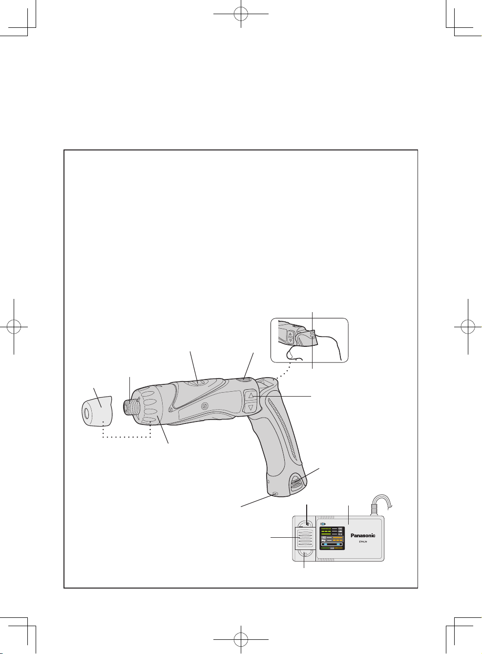
FUNCTIONAL DESCRIPTION
FUNKTIONSBESCHREIBUNG
DESCRIPTION DES FONCTIONS
DESCRIZIONE DELLE FUNZIONI
FUNCTIEBESCHRIJVING
DESCRIPCIÓN FUNCIONAL
BESKRIVELSE AF FUNKTIONERNE
FUNKTIONSBESKRIVNING
FUNKSJONSBESKRIVELSE
TOIMINTAKUVAUS
ФУНКЦИОНАЛЬНОЕ ОПИСАНИЕ
ФУНКЦIОНАЛЬНИЙ ОПИС
(A)
(F)
(D)
(B)
(C)
(G)
(H)
(I)
(J)
(N)
(M)
(L)
(K)
(E)
EY7410(EU).indb 2 2006/07/19 17:27:38
Page 3
-
3 -
(A)
Speed selector switch
Bereichsschalter
Sélecteur de vitesse de rotation
Selettore di velocità
Snelheidskeuzeschakelaar
Conmutador selector de velocidad
Hastighedsvælgeromskifter
Varvtals omkopplare
Gearvekger høy/lav
Nopeusalueen valitsin
RU
Ukr
(B)
Main switch lock
DE
FR
IT
NL
ES
DK
SE
NO
FI
RU
Ukr
(C)
Main switch
DE
FR
IT
NL
ES
DK
SE
NO
FI
RU
Ukr
(D)
Battery pack
Akkupack
Batterie
Pacco batteria
Accu
Bloque de pilas
Batteri
Batteri
Batteri-pakke
Akku
RU
Ukr
(E)
LED light
DE
FR
IT
NL
ES
DK
SE
NO
FI
RU
Ukr
(F)
Clutch handle
DE
FR
IT
NL
ES
DK
SE
NO
FI
RU
Uk
(G)
Clutch lock cover
DE
FR
IT
NL
ES
DK
SE
NO
FI
RU
Ukr
(H)
Hexagonal bit chuck
DE
FR
IT
NL
ES
DK
SE
NO
FI
RU
Ukr
EY7410(EU).indb 3 2006/07/19 17:27:39
Page 4
-
4 -
(I)
Battery low warning lamp
DE
FR
IT
NL
ES
DK
SE
NO
FI
RU
Ukr
(J)
LED light on/off button
DE
FR
IT
NL
ES
DK
SE
NO
FI
RU
Ukr
(K)
Battery charger (EY0L10)
Ladegerät (EY0L10)
Chargeur de batterie (EY0L10)
Carica-batterie (EY0L10)
Batterijlader (EY0L10)
Cargador de la batería (EY0L10)
Batterioplader (EY0L10)
Batteriladdare (EY0L10)
Batterilader (EY0L10)
Akkulaturi (EY0L10)
RU (EY0L10)
Ukr (EY0L10)
(L)
Ni-Cd battery pack dock
DE
FR
IT
NL
ES
DK
SE
NO
FI
RU
Ukr
(M)
Battery dock cover
DE
FR
IT
NL
ES
DK
SE
NO
FI
RU
Ukr
(N)
Li-ion battery pack dock
DE
FR
IT
NL
ES
DK
SE
NO
FI
RU
Ukr
EY7410(EU).indb 4 2006/07/19 17:27:40
Page 5
-
5 -
Read the Safety Instructions booklet and
the following before using.
I
. ADDITIONAL
SAFETY RULES
1) Wear ear protectors when using
the tool for extended periods.
Prolonged exposure to high inten
-
sity noise can cause hearing loss.
2) Be aware that this tool is always in
an operating condition, since it does
not have to be plugged into an electrical outlet.
3) When drilling into walls, floors, etc.,
“live” electrical wires may be encountered. DO NOT TOUCH THE CHUCK
OR ANY FRONT METAL PARTS OF
THE TOOL! Hold the tool only by the
plastic handle to prevent electric shock
in case you drill into a “live” wire.
4) If the bit becomes jammed, immedi
ately turn the main switch off to prevent an overload which can damage
the battery pack or motor.
Use reverse motion to loosen jammed
bits.
5) During charging, the charger may
become slightly warm. This is normal. Do not leave the battery in
the charger for more than 24 hours
after charging is completed.
[Tool and battery charger]
Symbol Meaning
V
Volts
Direct current
n
0
No load speed
…/min
Revolutions or reciprocations per
minutes
Ah
Electrical capacity of battery pack
[Battery charger]
Read the operating instructions
before use.
For outdoor use only.
II
. ASSEMBLY &
OPERATION
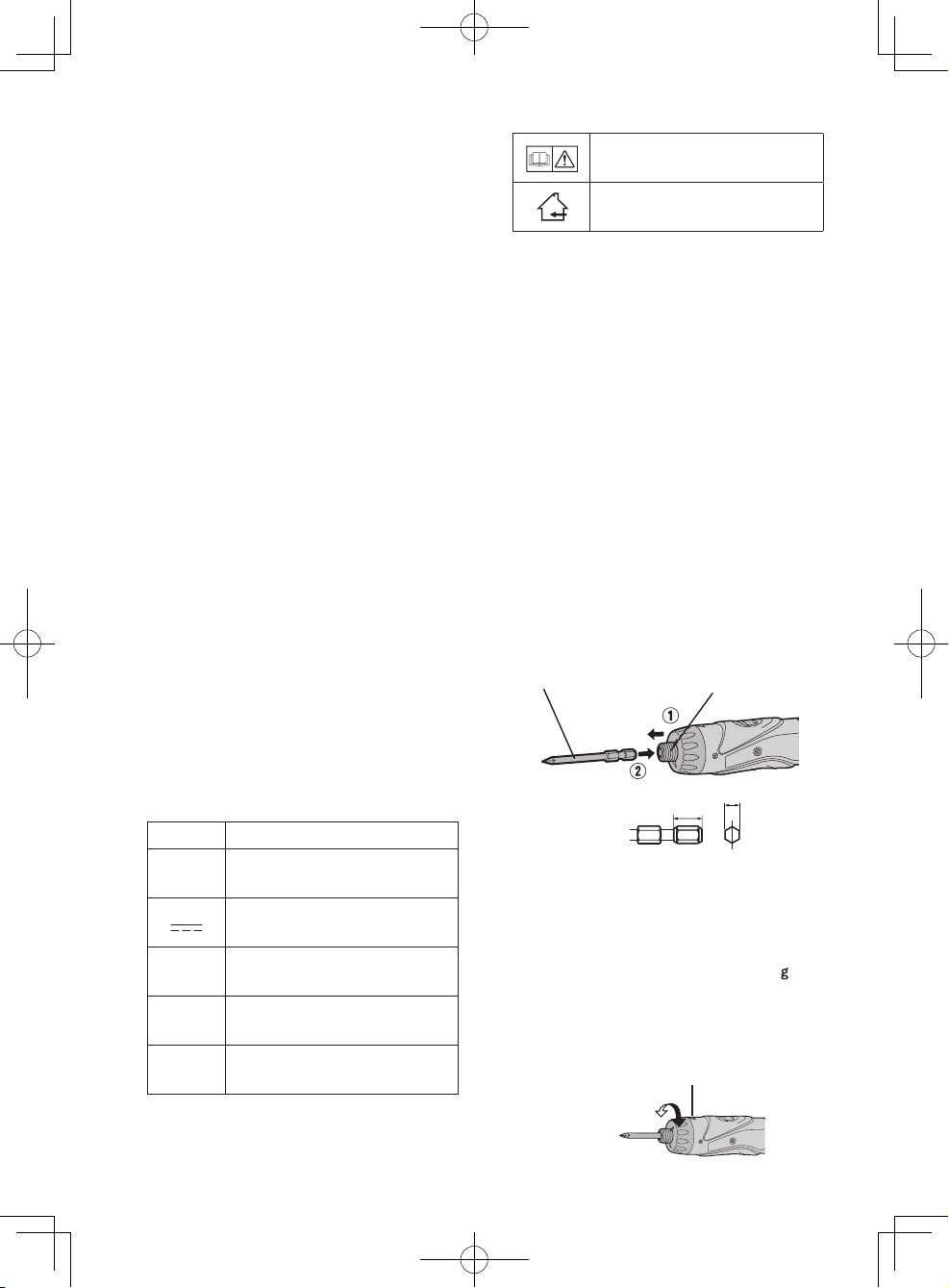
Hexagonal Bit Chuck
1. Attaching the bits
NOTE:
When attaching or removing drill
bits, disconnect the battery pack
from the tool and switch the lock
button into the lock position.
1. Hold the collar of the chuck and pull it.
2. Insert the bit into the chuck.
3. The collar will return to its original
position when it is released.
4. Pull the bit to make sure it does not
come out.
5. To remove the bit, pull back on the
collar in the same way.
Bit
Hexagonal bit chuck
9.5 mm (3/8") - 13 mm (00") 6.35 mm (1/4")
Clutch Handle
(Clutch Torque Setting)
Adjust the torque to one of the 21 possible settings to the job. There is an
interval of about 0.13 N·m (1.3 k
f-cm
or 1.1 in-lbs) between steps.
CAUTION:
Test the setting before actual operation.
Set the scale at this line.
EY7410(EU).indb 5 2006/07/19 17:27:42
Page 6

-
6 -
Reference for Adjusting Torque
Scale Torque Use
1
Approx: 0.29 N·m
(3.0 kgf-cm or 2.6 in-lbs)
For driving
screws
5
Approx: 0.82 N·m
(8.4 kgf-cm or 7.3 in-lbs)
9
Approx: 1.35 N·m
(13.8 kgf-cm or 12.0 in-lbs)
13
Approx: 1.88 N·m
(19.2 kgf-cm or 16.6 in-lbs)
17
Approx: 2.41 N·m
(24.6 kgf-cm or 21.3 in-lbs)
21
Approx: 2.94 N·m
(30.0 kgf-cm or 26.0 in-lbs)
Approx: 4.4 N·m
(45.0 kgf-cm or 39.0 in-lbs)
For powerful driving
screws and
drilling
● When using at high speeds, set the
scale at 10 or below. (Operation
stops at the maximum torque of 1.5
N·m (15 kgf-cm) when the scale is
higher.)
● The auto shut-off function may become inoperable at use at higher
scales when battery power drops.
Recharge the battery in that case.
NOTE:
The chart is only a reference. The
torque setting may differ by materials, types of screws, etc. Please test
it at your own conditions before use.
Battery Low Warning Lamp
<Battery low warning lamp>
Off
(normal
operation)
Flashing
(No charge)
Battery
protection
feature active
Excessive (complete) discharging of
Li-ion batteries shortens their service
life dramatically. The driver includes a
battery protection feature designed to
prevent excessive discharging of the
battery pack.
●The battery protection feature acti
-
vates immediately before the bat-
tery loses its charge, causing the
battery low warning lamp to flash.
●If you notice the battery low warn-
ing lamp flashing, charge the battery pack immediately.
Clutch Lock Cover
The clutch lock cover allows you to
lock the clutch at the selected graduation.
Attaching the cover
1. Select the torque required to move
the clutch.
2. Attach the clutch lock cover.
●Al ign the tri angle mark on the
cover with the graduation selection mark on the drill and attach.
Triangle mark Graduation selection
mark
Removing the cover
1. Grip the clutch lock cover with your
fingers on the mark and the bottom of the cover and remove.
●It will be difficult to remove the
clutch lock cover from the drill if
you push on the side of the cover
while pulling it off.
Using the LED Light
Use the LED li ght on job s in da rk
locations such as attics to illuminate
your workspace.
CAUTION
●TheLEDlightisintendedforuseas
a supplemental light source. Do not
useitasaashlight.
Doing so may result in accident or
injury.
EY7410(EU).indb 6 2006/07/19 17:27:45
Page 7

-
7 -
●Do not look at the light or shine it
directly into your eyes.
Continuous exposure to the LED
light may damage your eyes.
1. Pres s to toggle the light on
and off.
●To use the light immediately after
attaching the battery pack or after
the drill has not been used for 5
minutes or more, operate the drill
briefly.
●The light will automatically turn
off if the drill is not used for 5
minutes.
●The light uses an extremely small
amount of current. Using the light
ha s a negl i g ible eff e ct on t he
operational capacity of the drill.
● The LED is incapable of lighting
the tip of the bit when the drill is
usedinthestraightconguration.
Bit-locking Function
With the switch at off and the bit locked in place, the tool can be used as a
manual screw-driver - up to 14.7 N·m
(150 kgf-cm, 130 in-lbs).
There will be a little play in the driving
shaft, but this is not a malfunction.
Main Switch (ON/OFF)
Push the upper half of the switch for
forward rotation, or the lower half for
reverse rotation.
Forward
Forward
Reverse
Reverse
Speed Selector Switch
To suit the application of this tool, two
different rotational speeds are available. Depending upon use, either the
high or low speed should be selected.
HIGH
LOW
Speed selection Torque
LOW 200 /min (rpm) High
HIGH 600 /min (rpm) Low
CAUTION:
• Check speed selector switch before
use.
• Do not operate the speed selector
switch while the main switch is on
(switch is in the ON position).
Main Switch Lock
After use, set the main switch lock at
the lock position to prevent accidental
operation.
EY7410(EU).indb 7 2006/07/19 17:27:48
Page 8

-
8 -
Main switch lock
Lock
Battery Pack (EY9L10)
CAUTION:
1. Remove the battery pack away from
the tool.
2. Charge the battery pack using the
battery charger.
3. After charging has been completed,
remove the battery pack from the
charger and connect it to the tool.
Disconnect the charger from the
power source when not in use.
Battery Pack Life
The rechargeable batteries have a
limited life. If operation time becomes
ex t r emely shor t after recharging ,
replace the battery pack with a new
one.
NOTE:
Use under extremely hot or cold
conditions wi ll reduce operating
capacity per charge.
[Battery Pack]
For Appropriate use of Bat-
tery pack
Li-ion Battery pack (EY9L10)
•
For optimum battery life, do not charge
your lithium ion battery pack before
storing it following use of the driver.
• The ambient temperature range is
between 0°C (32°F) and 40°C (104°F).
If the battery pack is used when the
ba ttery tempe r ature is below 0°C
(32°F), the tool may fail to function
properly. In that case, charge the battery until charging is completed for
appropriate functioning of the battery.
• When battery pack is not in use,
keep it away from other metal objects
like: paper clips, coins, keys, nails,
screws, or other small metal objects
that can make a connection from one
terminal to another.
Shorting the battery terminals togeth
-
er may cause sparks, burns or a fire.
•
When operating th e battery pa ck,
make sure the work place is well ventilated.
Battery Pack Life
The r e chargeable batteries have
a limited life. If the operation time
be co me s ex tr em el y sh o r t af t e r
recharging, replace the battery pack
with a new one.
Battery Recycling
ATTENTION:
For environmental protection and
recycling of mate r i a l s , b e s u r e
that it is disposed of at an officially
assigned location, if there is one in
your country.
[Battery Charger]
Charging
Li-ion Battery Pack
NOTE:
Your battery pack is not fully charged at the time of purchase. Be sure
to charge the battery before use.
Battery charger (EY0L10)
1. Plug the charger into the AC outlet.
NOTE:
Sparks may be produced when the
plug is inserted into the AC power
supply, but this is not a problem in
terms of safety.
EY7410(EU).indb 8 2006/07/19 17:27:49
Page 9

-
9 -
2. Slide the battery dock cover back to
allow insertion of the lithium ion battery pack.
●Ve r ify t h at t h e cov e r is lo c k ed
securely in place.
3. Insert the battery pack firmly into the
charger.
To AC
outlet
4. During charging, the charging lamp
will be lit.
When charging is completed, an internal electronic switch will automatically
be triggered to prevent overcharging.
• Charging will not start if the battery
pack is warm (for example, immediately after heavy-duty operation).
The orange standby lamp will be lit
until the battery cools down.
Charging will then begin automati
-
cally.
5.
The charge lamp (green) will flash
slowly once the battery is approximately 80% charged.
6.
When ch a r g ing is co m p l eted, th e
charging lamp will start flashing quickly
in green color.
7. When in any of the conditions that
ba ttery pac k is too cool , cha rging
takes longer to fully charge the battery
pack than the standard charging time.
Even when the battery is fully charged,
it will have approximately 50% of the
power of a fully charged battery at
normal operating temperature.
8. If the power lamp does not light immediately after the charger is plugged
in, or if after the standard charging
time the lamp does not go off, consult
an authorized dealer.
9. If a fully charged battery pack is inserted int o the ch arger ag ain, the
charging lamp lights up. After several
minutes, the charging lamp may flash
quickl y to in dicate the char ging is
completed.
Ni-Cd Battery Pack
NOTE:
When you charge the battery pack
for the first time, or after prolonged
storage, c h a r g e it for about 24
hours to bring the battery up to full
capacity.
Battery charger (EY0L10)
1. Plug the charger into the AC outlet.
NOTE:
Sparks may be produced when the
plug is inserted into the AC power
supply, but this is not a problem in
terms of safety.
2. Slide the battery dock cover back to
allow insertion of the Ni-Cd battery
pack.
●Verifythatthecoverislockedsecurely
in place.
3. Insert the battery pack firmly into the
charger.
To AC
outlet
4.
During charging, the charging lamp will
be lit.
When charging is completed, an internal electronic switch will automatically
be triggered to prevent overcharging.
• Charging will not start if the battery
pack is warm (for example, immediately after heavy-duty operation).
The orange standby lamp will be
li t until the batte r y cools down.
Charging will then begin automatically.
5. When c h a rging is com p l e t e d, the
charging lamp will start flashing quickly in green color.
6. If the power lamp does not light im
mediately after the charger is plugged
in, or if after the standard charging
EY7410(EU).indb 9 2006/07/19 17:27:50
Page 10

-
10 -
time the lamp does not go off, consult
an authorized dealer.
7. If a fully charged battery pack is inserted int o the ch arger ag ain, the
charging lamp lights up. After several
minutes, the charging lamp may flash
quickl y to in dicate the char ging is
completed.
NOTE:
• When a cold battery (of about 0°C
or less) is to be charged in a warm
room, leave the battery in the room
for at least one hour and charge
it when it has warmed up to room
temperature. (Failing to do so may
result in less than a full charge.)
•
Cool down the charger when charging
more than two battery packs consecutively.
• Do not insert your fingers into contact hole, when holding charger or
any other occasions.
CAUTION:
To prevent the risk of fire or damage
to the battery charger.
• Do not use power source from an
engine generator.
• Do not cover vent holes o n the
charger and the battery pack.
• Unplug the charger wh en not in
use.
LAMP INDICATIONS
Orange Flashing
Both Orange and
Green Flashing Quickly
Green Lit
Green Flashing Quickly
Green Flashing
Green Lit
Orange Lit
Information on Disposal for Users of Waste Electrical &
Electronic Equipment (Private Households)
This symbol on the products and/or accompanying documents
means that used electrical and electronic products should not be
mixed with general household waste.
Fo r pr o per t reatme nt, rec overy and recycl ing, please take
these products to designated collection points, where they will
be accepted on a free of charge basis. Alternatively, in some
countries you may be able to return your products to your local
retailer upon the purchase of an equivalent new product.
Disposing of this product correctly will help to save valuable
resources and prevent any potential negative effects on human health and the
environment which could otherwise arise from inappropriate waste handling.
Charger is plugged into the AC outlet.
Ready to charge.
Charging is completed. (Full charge. Li-ion only)
Battery is approximately 80% charged. (Usable charge.
Li-ion only)
Now charging
Battery pack is cool.
The battery pack is being charged slowly to reduce the load
on the battery.
Battery pack is warm. Charging will begin when temperature of battery pack drops.
If the temperature of the battery pack is –10°C or less, the
charginglampwillalsostartashing.Chargingwillbeginwhen
the temperature of the battery pack goes up (Li-ion only).
Charging is not possible. Clogged with dust or malfunction
of the battery pack.
EY7410(EU).indb 10 2006/07/19 17:27:52
Page 11

-
11 -
Please contact your local authority for further details of your nearest designated
collection point.
Penalties may be applicable for incorrect disposal of this waste, in accordance with
national legislation.
For Business Users in the European Union
If you wish to discard electrical and electronic equipment, please contact your
dealer or supplier for further information.
Information on Disposal in Other Countries Outside the European Union
This symbol is only valid in the European Union.
If you wish to discard this product, please contact your local authorities or dealer
and ask for the correct method of disposal.
III
. MAINTENANCE
Use only a dry, soft cloth for wiping the unit. Do not use a damp cloth, thinner, benzine, or other volatile solvents for cleaning.
IV
. ACCESSORIES
Use only bits suitable for size of drill’s chuck.
V
. SPECIFICATIONS
MAIN UNIT
Model EY7410
Capacity
Screw driving
Machine screw M2.5 - M5
Wood screw ø 3.8 x 38 mm (5/32" x 1-29/64")
Drilling For metal ø 5 mm (13/64") spc t = 1.6 mm
Motor 3.6 V DC
No load speed
LOW: 200 rpm
HIGH: 600 rpm
Maximum torque
LOW: 4.4 N·m (45 k
gf-cm, 39 in-lbs)
HIGH: 1.5 N·m (15 kgf-cm, 13 in-lbs)
Maximum clutch torque 3.0 N·m (30 kgf-cm. 26 in-lbs)
Overall length 276 mm (10-55/64")
Weight (with battery pack) 0.5 kg (1.1 lbs)
EY7410(EU).indb 11 2006/07/19 17:27:52
Page 12

-
12 -
BATTERY PACK
Model EY9L10
Storage battery Li-ion Battery
Battery voltage 3.6 V DC (3.6 V x 1 cell)
BATTERY CHARGER
Model EY0L10
Weight 0.6 kg (1.3 lbs)
Electrical rating See the name plate on the bottom of the charger.
Charging time
2.4 V 3.6 V
1.2 Ah
EY9021
15 min.
EY9025
15 min.
1.5 Ah
EY9L10
Usable: 15 min.
Full: 30 min.
NOTE:
• For applicable battery packs to this charger, see the label on the charger or the
latest general catalog.
The instruction label on the battery packs also shows the applicable charger.
EY7410(EU).indb 12 2006/07/19 17:27:53
Page 13

-
13 -
ONLY FOR U. K.
VI
.
ELECTRICAL PLUG
INFORMATION
FOR YOUR SAFETY PLEASE READ
THE FOLLOWING TEXT CAREFULLY
This appliance is supplied with a moulded
three pin mains plug for your safety and
convenience.
A3ampfuseisttedinthisplug.
Should the fuse need to be replaced please
ensure that the replacement fuse has a
rating of 3 amp and that it is approved by
ASTA or BSI to BS1362.
Check for the ASTA mark or the BSI
mark on the body of the fuse.
If the plug contains a removable fuse cover
youmustensurethatitisrettedwhen the
fuse is replaced.
If you lose the fuse cover the plug must
not be used until a replacement cover is
obtained.
A re p l ac em en t f u s e co v e r c a n b e
pu r c h ased from your loca l Panas o n i c
Dealer.
IF THE FITTED MOUL D E D PL U G IS
UNSUITABLE FOR THE SOCKET OUTLET
I N YO U R HO M E TH E N TH E FU S E
SHOULD BE REMOVED AND THE PLUG
CUT OFF AND DISPOSED OF SAFELY.
TH E RE IS A D A N G ER OF SE VE R E
ELECTRICAL SHOCK IF THE CUT OFF
PLUG IS INSERTED INTO ANY 13 AMP
SOCKET.
Ifa newplugisto bettedpleaseobserve
the wiring code as shown below.
If in any doubt please consult a qualified
electrician.
IMPORTANT:
The wires in this mains lead are
colour e d i n a c cordan c e w i t h the
following code:
Blue: Neutral
Brown: Live
As the colours of the wire in the mains
lead of this appliance may not correspond
with the coloured markings identifying the
terminals in your plug, proceed as follows.
The wire which is coloured BLUE must be
connected to the terminal in the plug which
is marked with the letter N or coloured
BLACK.
The wire which is coloured BROWN must
be connected to the terminal in the plug
which is marked with the letter L or coloured
RED.
Un der no circum stances should eith er
of these wires be connected to the earth
terminal of the three pin plug, marked with
the letter E or the Earth Symbol .
How to replace the fuse: Open the fuse
compar t m e n t wit h a screw d r i v e r an d
replace the fu se and f use cover if it is
removable.
Fuse Cover
This apparatus was produced to BS800.
EY7410(EU).indb 13 2006/07/19 17:27:54
Page 14

Matsushita Electric Works, Ltd.
Osaka, Japan
No.1 EN. GR. FR. IT. ND. ES. DN. SW. NR. FN. RUS. Uk
EY971074101 H1808 Printed in Japan
EY7410(EU).indb 14 2006/07/19 17:27:54
 Loading...