

Panasonic EY7202 User Manual
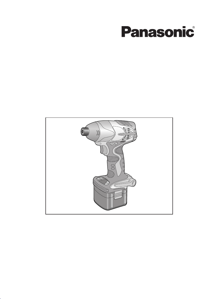
Cordless Impact Driver
Perceuse à impact sans fil
Destornillador de impacto inalámbrico
Operating Instructions
Instructions d'utilisation
Manual de instrucciones
Model No : EY7202
IMPORTANT
This manual contains safety information. Read manual completely before first using this product and save this
manual for future use.
IMPORTANT
Ce mode d’emploi contient des informations sur la sécurité. Lisez-le en entier avant d’utiliser le produit et
conservez-le pour référence.
IMPORTANTE
Este manual contiene información de seguridad. Lea completamente este manual antes de utilizar por primera
vez este producto, y guárdelo para poder consultarlo en el futuro.

Index/Index/Indice
English: Page 3
Français: Page 15
Español: Página 29
FUNCTIONAL DESCRIPTION
DESCRIPTION DES FONCTIONS
DESCRIPCIÓN FUNCIONAL
A B
N
M
L
I
H
JK
G
Fig. 1
C
D
E
O
F
6.35 mm (1/4”) hex quick connect chuck
A
Nose protector Protection du bec Protector del morro
B
Forward/Reverse lever
C
Belt hook lock lever
D
Belt hook Crochet de ceinture Gancho del cinturón
E
Battery pack release button Bouton de libération de batterie autonome Botón de liberación de batería
F
Battery pack (EY9201) Batterie autonome (EY9201) Batería (EY9201)
G
Bit holder (inside of the body) Porte-mèche (intérieur du corps)
H
Control panel Panneau de commande Panel de control
I
Impact power mode button
J
Digital clutch setting button
K
One-shot impact button
L
Variable speed control trigger Gâchette de commande de vitesse
M
LED light Lumière DEL Luz indicadora
N
Battery charger (EY0110) Chargeur de batterie (EY0110) Cargador de baterías (EY0110)
O
Mandrin de connexion rapide hexagonal de 6,35 mm (1/4")
Levier d’inversion marche avant/marche arrière
Levier de verrouillage du crochet de ceinture
Bouton de mode de puissance d'impact Botón de modo de potencia de impacto
Bouton de réglage d’embrayage numérique
Bouton d'impact à une seule percussion
-
2 -
Mandril hexagonal de conexión rápida de 6,35 mm (1/4")
Palanca de avance/marcha atrás
Palanca de bloqueo del gancho de cinturón
Soporte de broca (en el interior del cuerpo)
Botón de ajuste de embrague digital
Botón de impacto de un disparo
Disparador del control de velocidad variable

I. GENERAL SAFETY
RULES
WARNING! Read all instructions
Failure to follow all instructions listed below
may result in electric shock, fire and/or
serious injury. The term "power tool" in all
of the warnings listed below refers to your
mains operated (corded) power tool and
battery operated (cordless) power tool.
SAVE THESE INSTRUCTIONS
Work Area Safety
1) Keep work area clean and well lit.
Cluttered and dark areas invite accidents.
2)
Do not operate power tools in explosive
atmospheres, such as in the presence
of flammable liquids, gases or dust.
Power tools create sparks which may
ignite the dust or fumes.
3) Keep children and bystanders away
while operating a power tool.
Distractions can cause you to lose control.
Electrical Safety
1) Power tool plugs must match the outlet.
Never modify the plug in any way. Do
not use any adapter plugs with earthed
(grounded) power tools.
Unmodified plugs and matching outlets will
reduce risk of electric shock.
2) Avoid body contact with earthed or
grounded surfaces such as pipes, radi
ators, ranges and refrigerators.
There is an increased risk of electric shock
if your body is earthed or grounded.
3) Do not expose power tools to rain or
wet conditions.
Water entering a power tool will increase
the risk of electric shock.
4) Do not abuse the cord. Never use the
cord for carrying, pulling or unplugging
the power tool. Keep cord away from
heat, oil, sharp edges or moving parts.
Damaged or entangled cords increase the
risk of electric shock.
5)
When operating a power tool outdoors, use
an extension cord suitable for outdoor use.
Use of a cord suitable for outdoor use
reduces the risk of electric shock.
Personal safety
1)
Stay alert, watch what you are doing
and use common sense when operating
a power tool. Do not use a power tool
while you are tired or under the influ
ence of drugs, alcohol or medication.
-
-
A moment of inattention while operating
power tools may result in personal injury.
2) Use safety equipment. Always wear eye
protection.
Safety equipment such as dust mask,
non-skid safety shoes, hard hat, or hear
ing protection used for appropriate condi
tions will reduce personal injuries.
3)
Avoid accidental starting. Ensure the switch
is in the off position before plugging in.
Carrying power tools with your finger on
the switch or plugging in the power tools
that have the switch on invites accidents.
4) Remove any adjusting key or wrench
before turning the power tool on.
A wrench or a key left attached to a rotat
ing part of the power tool may result in
personal injury.
5) Do not overreach. Keep proper footing
and balance at all times.
This enables better control of the power
tool in unexpected situations.
6)
Dress properly. Do not wear loose clothing or jewellery. Keep your hair, clothing
and gloves away from moving parts.
Loose clothes, jewellery or long hair can
be caught in moving parts.
7) If devices are provided for the connec-
tion of dust extraction and collection
facilities, ensure these are connected
and properly used.
Use of these devices can reduce dust
related hazards.
Power tool use and care
1) Do not force the power tool. Use the
correct power tool for your application.
The correct power tool will do the job better
and safer at the rate for which it was designed.
2) Do not use the power tool if the switch
does not turn it on and off.
Any power tool that cannot be controlled
with the switch is dangerous and must be
repaired.
3) Disconnect the plug from the power
source and/or the battery pack from the
power tool before making any adjust
ments, changing accessories, or stor
ing power tools.
Such preventive safety measures reduce
the risk of starting the power tool acci
dentally.
4) Store idle power tools out of the reach
of children and do not allow persons
unfamiliar with the power tool or these
instructions to operate the power tool.
Power tools are dangerous in the hands of
untrained users.
-
-
-
-
-
-
-
3 -
-
4 -
5)
Maintain power tools. Check for misalignment or binding of moving parts, breakage
of parts and any other condition that may
affect the power tools operation. If damaged,
have the power tool repaired before use.
Many accidents are caused by poorly
maintained power tools.
6) Keep cutting tools sharp and clean.
Properly maintained cutting tools with sharp
cutting edges are less likely to bind and are
easier to control.
7) Use the power tool, accessories and
tool bits etc. in accordance with these
instructions and in the manner intend
ed for the particular type of power tool,
taking into account the working condi
tions and the work to be performed.
Use of the power tool for operations different
from those intended could result in a haz
ardous situation.
Battery tool use and care
1) Ensure the switch is in the off position
before inserting battery pack.
Inserting battery pack into power tools that
have the switch on invites accidents.
2) Recharge only with the charger specified by the manufacturer.
A charger that is suitable for one type of
battery pack may create a risk of fire when
used with another battery pack.
3) Use power tools only with specifically
designated battery packs.
Use of any other battery packs may create
a risk of injury and fire.
4) When battery pack is not in use, keep it
away from other metal objects like paper
clips, coins, keys, nails, screws, or other
small metal objects that can make a con
nection from one terminal to another.
Shorting the battery terminals together
may cause burns, or a fire.
5)
Under abusive conditions, liquid may be
ejected from battery; avoid contact. If contact
accidentally occurs, flush with water. If liquid
contacts eyes, additionally seek medical help.
Liquid ejected from the battery may cause
irritation or burns.
Service
1) Have your power tool serviced by a
qualified repair person using only iden
tical replacement parts.
This will ensure that the safety of power
tool is maintained.
WARNING
To reduce the risk of injury, user must
read instruction manual.
II. SPECIFIC SAFETY
RULES
1) Hold tool by insulated gripping surfaces when performing an operation
where the cutting tool may contact hid
den wiring.
Contact with a “live” wire will make
exposed metal parts of the tool “live”and
shock the operator.
2) Wear ear protectors when using the
-
-
-
-
-
tool for extended periods.
Prolonged exposure to high intensity noise
can cause hearing loss.
3)
Be aware that this tool is always in an
operating condition, it does not have to be
plugged into an electrical outlet.
4)
Do not operate the Forward/Reverse
lever when the Variable speed control
trigger is on.
The battery will discharge rapidly and
damage to the unit may occur.
5) If the bit becomes jammed, immediately
turn the Variable speed control trigger
off to prevent an overload which can
damage the battery pack or motor. Use
reverse motion to loosen jammed bits.
6) When storing or carrying the tool, set
the Forward/Reverse lever to the center
(switch lock) position.
7) Do not strain the tool by holding the
speed control trigger halfway (speed
control mode) so that the motor stops.
8)
During charging, the charger may
become slightly warm. This is normal. Do
not charge the battery for a long period.
Symbol Meaning
V
n
0
…/min
→
(Toward Chuck)
→
(Toward Motor)
reciprocation per minutes
Volts
Direct current
No load speed
Revolutions or
Forward rotation
Reverse rotation
-
-
5 -
WARNING!
Some dust created by power sanding, sawing, grinding, drilling, and other construction
activities contains chemicals known to the
State of California to cause cancer, birth
defects or other reproductive harm. Some
examples of these chemicals are:
• Lead from lead-based paints
• Crystalline silica from bricks and cement
and other masonry products
• Arsenic and chromium from chemicallytreated lumber.
To reduce your exposure to these chemicals: work in a well ventilated area, and
work with approved safety equipment, such
as dust masks that are specially designed
to filter out microscopic particles.
III. FOR
BATTERY CHARGER
& BATTERY PACK
Important Safety Instructions
1) SAVE THESE INSTRUCTIONS
ual contains important safety and operating
instructions for battery charger EY0110.
2) Before using battery charger, read all
instructions and cautionary markings on
battery charger, battery pack, and product
using battery pack.
3) CAUTION charge only Panasonic Battery Pack as
shown in last page.
Other types of batteries may burst causing
personal injury and damage.
4) Do not expose charger and battery pack to
rain or snow.
5) To reduce risk of damaging the electric
plug and cord, pull by plug rather than
cord when disconnecting charger.
6) Make sure cord is located so that it will not
be stepped on, tripped over, or otherwise
subjected to damage or stress.
7) An extension cord should not be used
unless absolutely necessary.
Use of improper extension cord could result
in a risk of fire and electric shock. If exten
sion cord must be used, make sure that:
a.
pins on plug of extension cord are the
same number, size and shape as those of
plug on charger.
b. extension cord is properly wired and in
good electrical condition.
c. wire size is large enough for ampere
rating of charger as specified below.
To reduce the risk of injury,
-This man-
RECOMMENDED MINIMUM AWG SIZE OF
AC Input Rating. Amperes
Equal to or
greater than
0 2 18 18 18 16
8) Do not operate charger with damaged
9) Do not operate charger if it has received
10)Do not disassemble charger; take it to a
11)To reduce the risk of electric shock, unplug
12)The charger and battery pack are specif-
13)Do not attempt to charge the battery pack
14)Do not attempt to disassemble the battery
15)Do not store the tool and battery pack in loca-
16)Do not charge battery pack when the tem-
17)Do not incinerate the battery pack. It can
18)Avoid dangerous environment. Do not use
19)The charger is designed to operate on stan-
20)Do not abuse cord. Never carry charger by
-
21)Charge the battery pack in a well ventilated
22)Use of an attachment not recommended
EXTENSION CORDS FOR
BATTERY CHARGERS
But less
than
cord or plug-replace them immediately.
a sharp blow, been dropped, or otherwise
damaged in any way; take it to a qualified
service personnel.
qualified service personnel when service
or repair is required. Incorrect reassembly
may result in a risk of electric shock or fire.
charger from outlet before attempting any
maintenance or cleaning.
ically designed to work together. Do not
attempt to charge any other cordless tool
or battery pack with this charger.
with any other charger.
pack housing.
tions where the temperature may reach or
exceed 50°C (122°F) (such as a metal tool
shed, or a car in the summer), which can
lead to deterioration of the storage battery.
perature is BELOW 0°C (32°F) or ABOVE
40°C (104°F). This is very important in
order to maintain optimal condition of the
battery pack.
explode in a fire.
charger in damp or wet locations.
dard household electrical power only. Do not
attempt to use it on any other voltage!
cord or yank it to disconnect from outlet. Keep
cord away from heat, oil and sharp edges.
place, do not cover the charger and battery
pack with a cloth, etc., while charging.
may result in a risk of fire, electric shock,
or personal injury.
AWG Size of Cord
Length of Cord,
Feet
25 50 100 150
-
6 -
23
) Do not short the battery pack. A battery
short can cause a large current flow, over
heating and create the risk of fire or per
sonal injury.
24)NOTE: If the supply cord of this appliance
is damaged, it must only be replaced by a
repair shop authorized by the manufacturer,
because special purpose tools are required.
25)TO REDUCE THE RISK OF ELECTRIC
SHOCK, THIS APPLIANCE HAS A POLAR
IZED PLUG (ONE BLADE IS WIDER THAN
THE OTHER).
This plug will fit in a polarized outlet only one
way. If the plug does not fit fully in the outlet,
reverse the plug. If it still does not fit, contact
a qualified electrician to install the proper
outlet. Do not change the plug in any way.
IV. ASSEMBLY
Attaching or removing bit
NOTE:
•
When attaching or removing a bit, disconnect battery pack from tool or place the
switch in the center position (switch lock).
1. Hold the collar of quick connect chuck and
pull it against the driver.
2. Insert the bit into the chuck.
3. The collar will return to its original position
when it is released.
4.
Pull the bit to make sure it does not come out.
5. To remove the bit, pull back on the collar
in the same way.
CAUTION:
•
If the collar does not return to its original
position or the bit comes out when pulled on,
the bit has not been properly attached. Make
sure the bit is properly attached before use.
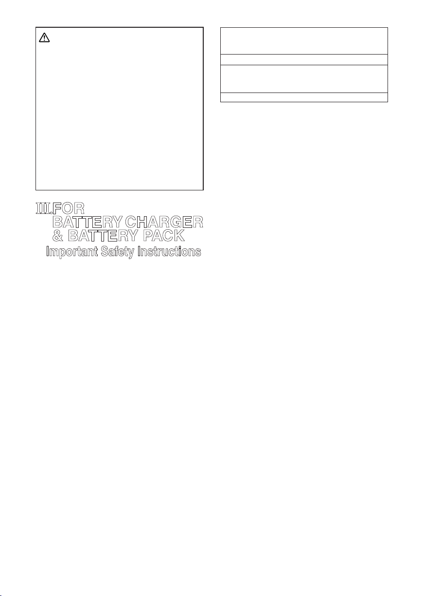
Use 6.35mm (1/4”) hexagonal bits.
To ensure proper securement of the bit, use
only hexagonal bits with 9.5mm (3/8”) detent.
6.35mm (1/4”)
Attaching or removing
battery pack
1. To connect the battery pack:
Insert the battery pack. It snaps into place
to indicate proper connection.
2. To remove the battery pack:
Press the two buttons on the sides of the
battery pack. Slide the battery pack out of
the tool body.
9.5mm (3/8”)
V. OPERATION
-
Switch and Forward / Reverse
lever Operation
CAUTION:
•
To prevent damage, do not
operate Forward/Reverse
-
(Forward, Lock, Reverse)
Forward Rotation Switch
Operation
1. Push the lever for forward rotation.
2.
Depress the trigger switch slightly to start the
tool slowly.
3. The speed increases with the amount of
depression of the trigger for efficient tight
ening of screws. The brake operates and
the bit stops immediately when the trigger
is released.
4. After use, set the lever to its center position (switch lock).
Reverse Rotation Switch
Operation
1.
Push the lever for reverse rotation. Check
direction of rotation before use.
2.
Depress the trigger switch slightly to start the
tool slowly.
3. After use, set the lever to its center position (switch lock).
CAUTION:
• To eliminate excessive temperature
increase of the tool surface, do not oper
ate the tool continuously using two or
more battery packs. Tool needs cool off
time before switching to another pack.
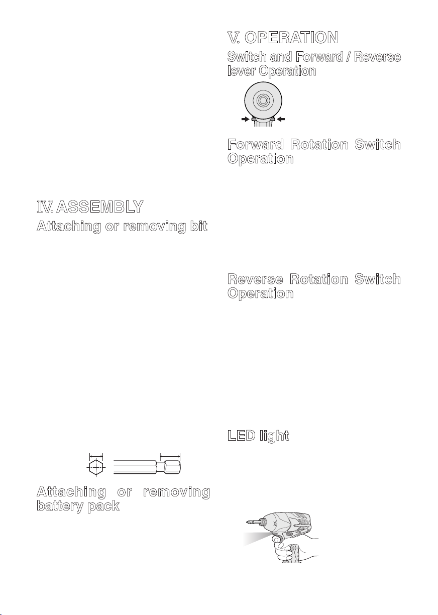
LED light
CAUTION:
• The built-in LED light is designed to illuminate the small work area temporarily.
• Do not use it as a substitute for a
regular flashlight, since it does not have
enough brightness.
lever until the bit comes to
a complete stop.
Depress the trigger
switch, then LED
light turns on. When
the trigger switch is
released, the light
turns off automati
cally.
-
the
-
-

-
7 -
The light illuminates with very low current, and it does not adversely affect the
performance of the driver during use or its
battery capacity.
How to use the belt hook
WARNING!
• Be sure to attach the belt hook securely
to the main unit with the screw firmly
fastened. When the belt hook is not firmly
attached to the main unit, the hook may
depart and the main unit may fall.
This may result in an accident or injury.
• Periodically check screw for tightness. If
found to be loose, tighten firmly.
• Be sure to attach the belt hook firmly and
securely onto a waist belt or other belt.
Pay attention to the unit not slipping off
from the belt.
This may result in an accident or injury.
• When the main unit is held by the belt
hook, avoid jumping or running with it.
Doing so may cause the hook to slip and
the main unit may fall.
This may result in an accident or injury.
• When the belt hook is not used, be sure
to return it to the storing position. The belt
hook may catch on something.
This may result in an accident or injury.
• When the unit is hooked onto the waist
belt by the belt hook, do not attach driver
bits to the unit.
A sharp edge object, such as a drill bit,
may cause injury or an accident.
To set the belt hook angle
position
1. Slide the belt hook lock lever 1 and hold
it to unlock the belt hook.
2. Pull the belt hook from
storing position 2 and
set it as desired angle.
3.
Release the belt hook
lock lever to
angle of belt hook.
4.
Make sure the belt hook is firmly locked
3
. Also make sure the belt hook is firmly
locked into position.
• The belt hook cannot
be locked in this position. Firmly lock it into
position before use.
To return the belt hook to the storing position,
lock the
2
1
3
Follow step 1. and 2. above, then lower the
belt hook.
To secure the lock, follow 3 and 4 above.
To change the belt hook
location side
The belt hook can be attached to either
side of the unit.
1. Set the belt hook at storing position.
2. Loosen the screw turning it counterclockwise, using a coin or a flat blade
screw driver.
3.
Take out the belt hook and insert into the
other side of the slot on the main unit.
4. Fasten the screw firmly, turning it clockwise.
The belt hook can be taken out from the
main unit only when it is at storing position.
Additional Power Control
Functions
Quick Reference for Features and Functions
Impact power mode select:A(See p.8.)
→
This unit is equipped with impact power
mode button.By pressing impact power
mode button, soft
impact mode and hard impact mode can
be selected (3 settings).
∗
Please use this together with digital
clutch setting.
Digital clutch : B (See p.9.)
→
This unit is equipped with the digital clutch
function.
The driver rotation will stop when the set
clutch load is reached.
∗
Please use this together with impact
power mode select.
This digital clutch is not intended for
controlling the accuracy of the fastening torque.
Example application not to be used;
impact mode, medium
C
AB

-
8 -
To control the shut-off torque used to
tighten screws and bolts for manufacturing and assembly.
Do not use the digital clutch when
tightening screws with a low tightening torque into materials, such as thin
plastic.
Example application not to be used;
When tightening screws into lightweight
steel sheet which thickness is 0.8 mm
or less.
When tightening screws into soft surface
materials, such as interior finishing
materials.
One-shot impact function :
→
Set the one-shot impact function to
tighten screws slightly to adjust the
screw head flush to the material surface.
Select the clutch setting to match the
application. This is used when readjust
ing is continuously required.
The driver automatically rotates approx-
imately half round and stops each time
the trigger switch is depressed. (For bolts,
it stops after approximately 5 impacts.)
Within 1 sec. after the trigger switch is
released once, if it is depressed again,
the one-shot impact function will auto
matically operate.
Indication lights on the control panel
The indication lights will go off in the
following cases.
• The driver is not operated for 5 min.
• When the battery is replaced.
Depressing the trigger switch again, then
indication lights go on in the previous
condition.
C
Main recommended applications
and setting guidelines.(see p.13.)
Be sure to set the impact power mode
and digital clutch to match the material
and screws being used for the application.
Adjust the settings from low to high
while checking them to settle on a final
setting for impact power mode select
and for digital clutch setting.
When driving screws into wood, use
the screws of less than 90 mm long and
avoid knots of wood materials.
∗
One-shot impact function requires the
impact power mode select and digital
clutch settings.
Impact Power Mode Select
Selecting the impact power among 3
modes (Hard, Medium, Soft).
Press the impact power mode button to
set it. The mode changes to hard, medium,
or soft each time the button is pressed. To
use automatic mode shifting, press the
button for a period (0.6 sec. or more). It
is recommended that the impact power
mode select be used together with the
digital clutch setting and one-shot impact
function.
The driver is preset to “hard” impact mode
-
setting when shipped from the manufacturer.
Impact power mode button
Recommended work guideline table
When maximum power is required in each
impact mode, set the clutch to the “F” mode.
Impact
Power mode
Display
-
H
Approx.
2,800R.P.M.(Max.
M
Approx.
2,500R.P.M.(Max.
S
Approx.
2,000R.P.M.(Max.
Recommended Application
For hard impact power mode.
Fastening long wood screws.
Tightening bolts when installing devices, etc.
)
For medium impact power mode.
Fastening small diameter
screws into hard materials.
Driving machine screws when
installing devices.
)
For soft impact power mode.
Installing gypsum board.
Installing soft metal window
ame.
Installing interior nishings.
)
One-Shot Impact Function
This function helps adjust the screw head
flush to the material surface.
The driver rotates half round∗ and auto-
matically stops each time the trigger
switch is depressed while tightening a
screw. The driver will give impact about
5 times and automatically stop while
tightening a bolt even though the trigger
switch is depressed. The one-shot impact
function is also available in reverse rota
tion. The impact force is set by the impact
power mode select and digital clutch set
tings.
-
-

-
9 -
NOTE:
∗ The one-shot impact function operates
after impact. Over-tightening may occur
when tightening screws into soft materials as the tool does not impact.
Using the one-shot impact function
When the trigger switch is released
and it is depressed fully within
1 sec., one-shot impact function operate. Then
impact LED light will blink.
Wait at least 1 sec. after
trigger is released, not
to operate the one-shot
impact function.
Keeping the bit head to the screw head to use
this function.
When the screw is sticking up quite a ways,
increase the clutch setting.
the one-shot
Using the one-shot impact function
continuously
Refer to the guideline table (See p.13.) and
check the application. Press the impact power
mode button () to select the setting. Select
the digital clutch setting () that matches the
application. To set the one-shot impact function, press the button () then light () turns
on. Depress the trigger switch fully to adjust
the screw tightening until the one-shot impact
function operates. The amount of screw fastening rotation by one-shot impact will differ
depending on the impact power mode and
digital clutch settings. To turn off the one-shot
impact function, press the button () once
more then light () turns off.
Digital Clutch
The digital clutch automatically stops the
driver rotation when the load is reached
to the select setting. Depress the trigger
switch fully to tighten the screws until the
digital clutch operates. If the screw head
is not flush to the material surface, release
the trigger switch and then within 1 sec.
depress it again. This will operate the oneshot impact function.
To select digital clutch setting.
Refer to the guideline table and check the
application. (See p.13.)
Press the impact power mode button to set
the impact power mode. (See p.8.)
Press the digital clutch setting buttons and
select the setting to match the application.
The digital clutch setting increases each
time (+) button is pressed.
The setting decreases
each time (-) button is
pressed.
Digital clutch setting range
Setting is available from 1 to 16 stages to
match the application.
Keep pressing the and
button 0.6 sec or more
will automatically shift the
Full power
setting to “F”. (Digital clutch
is turned off in the each
impact power mode.)
Turn off the digital clutch.
Press the digital clutch
setting button to change
the setting to “F.”
NOTE:
When selecting the digital clutch set-
ting, first start at a low setting and a soft
impact mode. Then gradually select to
higher settings. Try on a scrap piece of
the material to determine the best setting beforehand. Too high setting could
result in over-tightening of the screws.
Keep the trigger switch fully depressed
while tightening one screw to operate
the digital clutch. Do not release the trigger switch until digital clutch operates.
The clutch setting remains the same
when the driver is changed from forward to reverse rotation while the clutch
is set. To drive in reverse at full power,
change the clutch setting display to “F”
and turn off the digital clutch.
The driver is preset to “F” full power
(digital clutch is off) and the one-shot
impact function is off when shipped
from the manufacture.
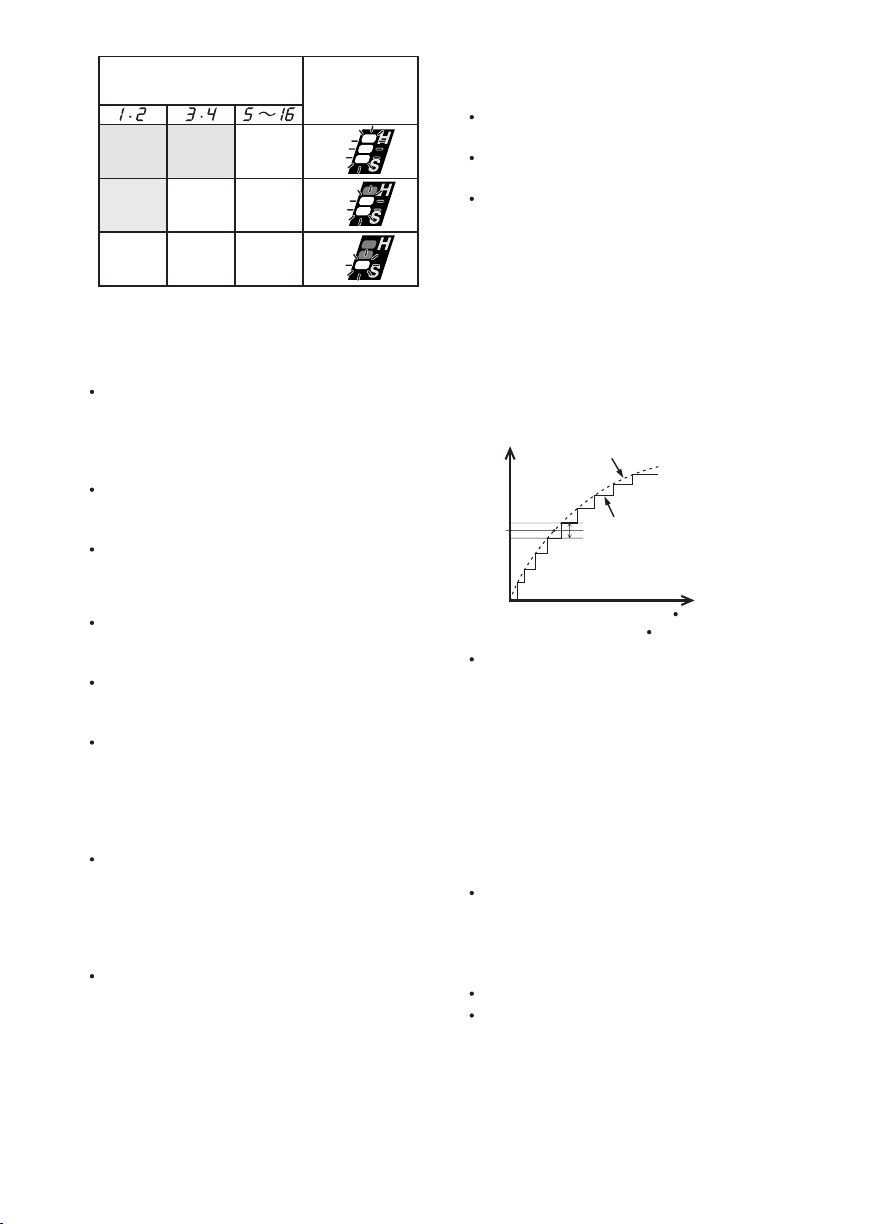
CAUTION:
When the clutch is set to 1 or 2 stage, the
impact power mode is automatically set
at “Soft” impact mode regardless of the
impact power mode select display setting.
When the clutch is set to 3 or 4 stage,
the impact powermode is automatically
set at “Medium” impact mode even in
the “Hard” impact mode display setting.
-
10 -
Clutch setting and
operating impact force
Soft Medium Hard
Soft Medium Medium
Soft Soft Soft
Impact
Power Mode
Display
H
M
S
Important remarks when using
the digital clutch and one shot
impact functions
The digital clutch setting could be used
only as a guideline. The suitable setting
will vary depending on the hardness of
the material, the force being applied to the
tool, and the type of screw.
Uneven material hardness could result in
less-tightening or over-tightening depend
ing on the position on the material.
If the battery pack capacity is low, the
driver might not fully tighten the screws.
Usage
When driving screws into wood, use the
screws of less than 90 mm long and avoid
knots of wood materials.
Be sure to set the impact power mode
and digital clutch to match the material
and screws being used.
When selecting the digital clutch settings,
start from low to high stage while check
ing the setting (on a scrap piece of the
material) to determine the best setting.
Too high setting could result in over-tight
ening of the screws.
Depress the trigger switch fully when
using the digital clutch and/or one-shot
impact function during one period of oper
ation. Using low speed by trigger switch
could result in a discrepancy in work
results.
When using the digital clutch, depress the
trigger switch fully until the digital clutch
operates. Do not release the switch until
the rotation stops. Releasing the switch
to stop rotation before finishing tighten
ing a screw could result in not being fully
tightened. (If this happens, start from the
beginning of fastening.)
Applications not recommended
for these functions
Tightening screws into easily breakable
materials, such as thin plastics.
Tightening screws into lightweight steel
sheet which thickness is 0.8 mm or less.
Tightening TEKS screws into soft surface
materials, such as interior finishing materials.
Reason: The impact function is a
mechanical sideway impact. The tight
ening torque increases instantly step by
step when the hammer impacts. There
fore, fastening torque of impact driver is
not generally increased as a drill driver.
(The accuracy also varies depending on
the material.)
Impact torque curve
Tightening torque (load)
Drill driver torque increase.
-
Setting value
To control the tightening torque for screws
and bolts during factory manufacturing
and assembly.
Reason: The digital clutch uses a sen-
sor and microcomputer to deduce the load
-
-
-
-
from the number of motor rotation between
impacts and then stop the rotation when
the load reaches to the set clutch load.
To deduce this load requires at least 4 or
5 impacts, This is not suitable for materi
als which requires a low tightening load, as
impact may not occur 4 or 5 times.
The digital clutch cannot operate accurately when the connecting surface material is
soft and the fixing base sheet is hard.
Example applications for which it cannot
be used;
Attaching gypsum board on hard wood.
Tightening screws with different lengths,
diameters, thread pitches, etc., even if
they are the same type of screw.
Impact torque curve
Tightening time
Number of impacts
-
-
-
-
11 -
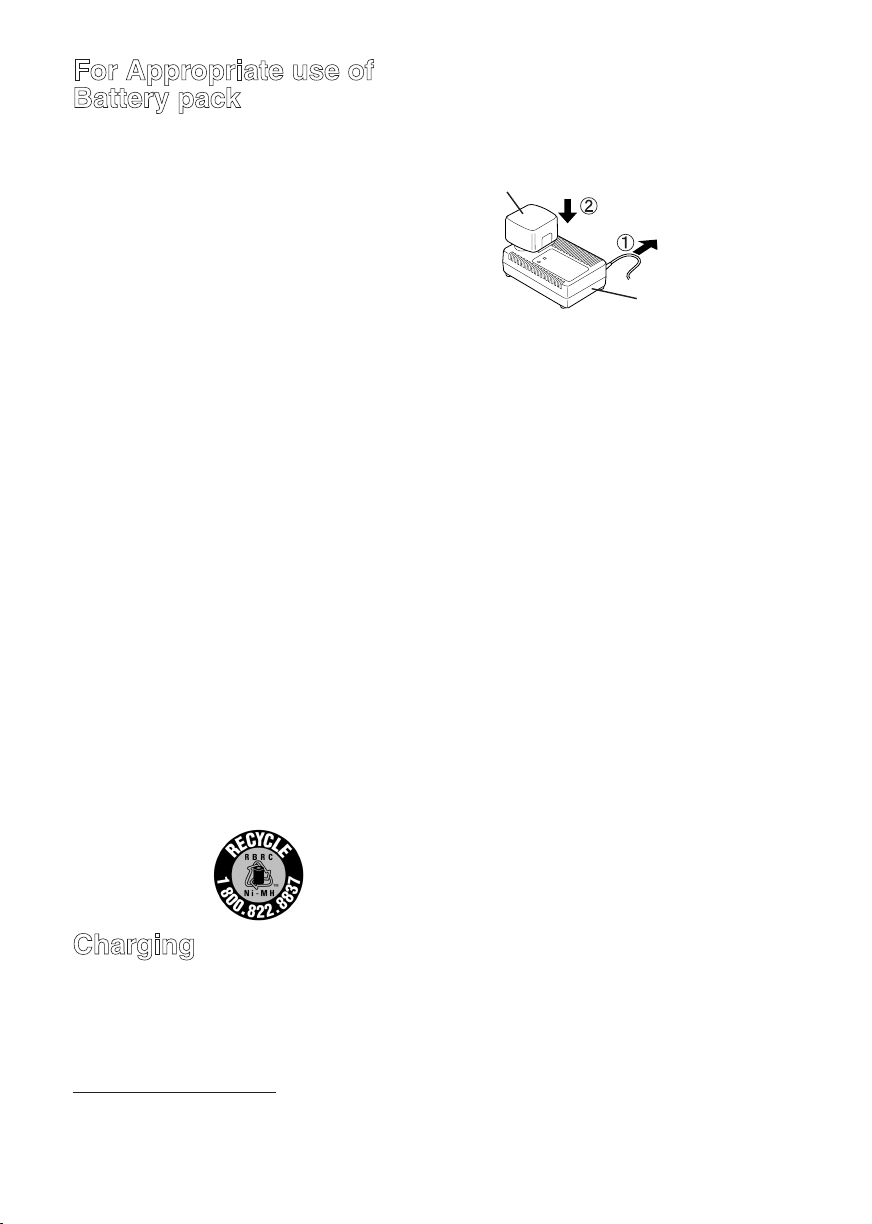
For Appropriate use of
Battery pack
Ni-MH Battery pack (EY9201)
• Charge the Ni-MH battery fully before
storage in order to ensure a longer ser
vice life.
• The ambient temperature range is
between 0°C (32°F) and 40°C (104°F).
If the battery pack is used when the bat-
tery temperature is below 0°C (32°F), the
tool may fail to function properly. In that
case, charge the battery until charging is
completed for appropriate functioning of
the battery.
• When battery pack is not in use, keep it
away from other metal objects like: paper
clips, coins, keys, nails, screws, or other
small metal objects that can make a con
nection from one terminal to another.
Shorting the battery terminals together
may cause sparks, burns or a fire.
• When operating with a Ni-MH battery pack,
make sure the place is well-ventilated.
Battery Pack Life
The rechargeable batteries have a limited life. If the operation time becomes
extremely short after recharging, replace
the battery pack with a new one.
Battery Recycling
ATTENTION:
FOR Ni-MH Battery Packs, EY9201
A nickel metal hydride battery that is
recyclable powers the product you have
purchased.
Please call 1-800-8-BATTERY for informa
tion on how to recycle this battery.
NOTE:
Sparks may be produced when the plug
is inserted into the AC power supply, but
this is not a problem in terms of safety.
2.
Insert the battery pack firmly into the charger.
-
-
-
Battery pack
To AC
outlet
3.
During charging, the charging lamp will be lit.
When charging is completed, an internal
electronic switch will automatically be trig
gered to prevent overcharging.
• Charging will not start if the battery
pack is warm (for example, immediately
after heavy-duty operation).
The orange standby lamp will be lit until
the battery cools down. Charging will
then begin automatically.
4. When charging is completed, the charging lamp will start flashing quickly in green
color.
5. When in any of the conditions that battery
pack is too cool, or the batter y pack
has not been used for a long time, the
charging lamp is lit. In this case charging
takes longer to fully charge the battery
pack, than the standard charging time.
• If a fully charged battery pack is inserted into the charger again, the charging
lamp lights up. After several minutes,
the charging lamp may flash quickly to
indicate the charging is completed.
6.
If the charging lamp does not light
ately after the charger is plugged in, or if
after the standard charging time the lamp
does not go off, consult an authorized
dealer.
Battery charger
-
immedi-
Charging
NOTE:
When you charge the battery pack for
the first time, or after prolonged storage,
charge it for about 24 hours to bring the
battery up to full capacity.
Battery charger (EY0110)
1. Plug the charger into the AC outlet.
NOTE:
• When charging a cool battery pack
(below 5°C (41°F)) in a warm place,
leave the battery pack at the place and
wait for more than one hour to warm up
the battery to the level of the ambient
temperature. Otherwise battery pack
may not be fully charged.
•
Cool down the charger when charging
more than two battery packs consecutively.
• Do not insert your fingers into contact
hole, when holding charger or any other
occasions.

-
12 -
CAUTION:
0.5 1 1.5 2 32.5
M12
M10
M8
Tightening time (Sec.)
Tightening torque
M8.M10.M12 x 25mm Standard bolt
(Bolt size : Millimeters)
N ⋅ m
(kgf-cm)
19.6
(200)
39.2
(400)
58.8
(600)
78.5
(800)
98.1
(1000)
M8.M10.M12 x 25mm High tensile bolt
0.5 1 1.5 2 32.5
M12
M10
M8
Tightening time (Sec.)
Tightening torque
19.6
(200)
39.2
(400)
58.8
(600)
78.5
(800)
98.1
(1000)
117.6
(1200)
N ⋅ m
(k
gf-cm)
Explanation of the strength type
6.8
Bolt yield point
(80% of tenslie strength)
48
k�f/mm2(68,000psi)
Bolt tensile strength 60
k�f/mm
2
(85,000psi)
To prevent the risk of fire or damage to
the battery charger.
• Do not use power source from an
engine generator.
• Do not cover vent holes on the charger
and the battery pack.
• Unplug the charger when not in use.
VI. LAMP INDICATIONS
Red Flashing
Red Lit
Green Flashing quickly
Orange Lit
Orange Flashing
Charger is plugged into the AC outlet.
Ready to charge.
Now charging
Charging is completed.
Battery pack is warm. Charging will begin
when temperature of battery pack drops.
Charging is not possible. Clogged with
dust or malfunction of the battery pack.
Bolt Tightening Conditions
VII. MAINTENANCE
Use only a dry, soft cloth for wiping the unit.
Do not use a damp cloth, thinner, benzine,
or other volatile solvents for cleaning.
VIII
. TIGHTENING TORQUE
The power required for tightening a bolt
will vary, according to bolt material and
size, as well as the material being bolted.
Choose the length of tightening time
accordingly.
Reference values are provided below.
(They may vary according to tightening conditions.)
Factors Affecting Tightening
Torque
The tightening torque is affected by a wide
variety of factors including the followings.
After tightening, always check the torque
with a torque wrench.
1) Voltage
When the battery pack becomes nearly
discharged, the voltage decreases and the
tightening torque drops.
Bolt
Nut
Washer
Steel plate
thickness10mm(3/8")
Washer
Spring washer
Tightening conditions
• The following bolts are used.
Standard bolts: Strength type 6.8
High tensile type 12.9

-
13 -
2) Tightening time
Longer tightening time results in increased
tightening torque. Excessive tightening,
however, adds no value and reduces the
life of the tool.
3) Different bolt diameters
The size of the bolt diameter affects the
tightening torque.
Generally, as the bolt diameter increases,
tightening torque rises.
4) Tightening conditions
Tightening torque will vary, even with the
same bolt, according to grade, length, and
torque coefficient (the fixed coefficient indicated by the manufacturer upon production).
Tightening torque will vary , even with
the same bolting material (e.g. steel),
according to the surface finish.
Torque is greatly reduced when the bolt
and nut start turning together.
5) Socket play
Torque is lowered as the six-sided configuration of the socket of the wrong size is
used to tighten a bolt.
6) Switch (Variable speed control trigger)
Torque is lowered if the unit is used with
the switch not fully pulled out.
7) Effect of Connecting Adaptor
The tightening torque will be lowered
through the use of a universal joint or a
connecting adaptor.
IX. ACCESSORIES
Use only bits suitable for size of chuck.
X. APPENDIX
MAXIMUM RECOMMENDED CAPACITIES
Model
Screw
driving
Bolt fastening
Wood screw
Self-drilling screw
3.5 - 9.5 mm (1/8" - 3/8")
Standard bolt : M6 - M12
High tensile bolt
GUIDELINE TABLE
Impact
Fixing material
(thickness)
2
4" Material 2
Plywood
12 mm (1/2")
Gypsum board
12 mm (1/2")
SPC
1.2 mm (1/16")
4" Material 2
2
NOTE:
• When screwing TEKS screws into hard materials, use the lighter digital clutch’s setting to
avoid slippage which may chip or damage the screw. For the final tightening, use the oneshot impact function.
• Depending on the type of screw or the hardness of the material, the screw may not be completely flush with the surface. When working with cabinet boards or other more decorative
materials where screws need to sit flush on the surface, use the lighter digital clutch’s setting
to avoid damaging the material, and then finish using the one-shot impact function.
Base material
4" Material
2
4" Material
2
4" Material
SPC
1.2 mm (1/16")
4" Material
Screw
(Size)
Drywall screw
4.2
75
(3/16"
3")
Drywall screw
3.8
28
(1/8"
1-1/4")
Drywall screw
3.8
28
(1/8"
1-1/4")
Self-drilling screw
1.3
4
1/2")
(3/16"
Coach screw
50
9
1-15/16")
(3/8"
power
mode
H M S
EY7202
3.5 - 6 mm (1/8" - 1/4")
: M6 - M10
Clutch setting stage reference
1 2 3 4 5 6 7 8 9
10 11 12 13 14 15 16

XI. SPECIFICATIONS
MAIN UNIT
Model EY7202
Motor DC Motor 12 V
soft mode 0 - 2000 /min
No load speed
Maximum torque 120 Nm (1220 k
Impact per minute
Overall length 167 mm (6-9/16")
Weight (with battery pack : EY9201) 1.85 k
BATTERY PACK (EY9201 is included with shipment. )
Model EY9201 EY9200
Battery voltage 12 V DC (1.2 V × 10 cells)
Storage Battery Ni-MH Battery Ni-Cd Battery
Capacity 3.5 Ah 3.0 Ah 2.0 Ah 1.7 Ah 1.2 Ah
BATTERY CHARGER
Model EY0110
Rating See the rating plate on the bottom of the charger.
Weight 0.78 k
Charging time 55 minutes (EY9201)
NOTE:
• Do not charge “Y” type Ni-Cd battery packs.
• For applicable battery packs to this charger, see the label on the charger or the latest gen-
eral catalog.
The instruction label on the battery packs also shows the applicable charger.
mediun mode 0 - 2450 /min
hard mode 0 - 2600 /min
f-cm, 1060 in-lbs.)
soft mode 0 - 2000 /min
mediun mode 0 - 2500 /min
hard mode 0 - 2800 /min
(4.1 lbs)
EY9106, EY9107
EY9101
(1.72 lbs)
EY9001, EY9006
-
14 -
 Loading...