

Page 1

Operating Instructions
Functional Manual
DIGITAL LINK Switcher
Model No.
ET-YFB200G
Commercial Use
Thank you for purchasing this Panasonic product.
■Before operating this product, please read the instructions carefully and save this manual
for future use.
■Before using this product, be sure to read “Read this rst!” (
pages 4 to 9).
ENGLISH
TQBH0389
Page 2

Contents
Contents
Read this rst! 4
Chapter 1 Preparation
Precautions for use 13
Cautions when transporting
Cautions when installing
DIGITAL LINK
Early Warning Software
Disposal
Accessories
Optional accessories
About your device
Main body
13
13
14
14
14
15
16
17
17
Chapter 2 Getting Started
Setting up 21
Mounting on a rack
Placing on a desk or a shelf
Connecting
Before connecting
Connecting example: Image input device and
audio device
Connecting example: Computers
Connecting example: Image display device
21
21
23
23
24
25
25
Chapter 3 Basic Operations
Turning on/off the device 31
Connecting the AC adapter
Turning on the power of the DIGITAL LINK
Switcher
Turning off the power of the DIGITAL LINK
Switcher
Turning on/off the power of the display
Before turning off/on the power of the display
Turning on the power of the display
Turning off the power of the display
Checking the image
Selecting the image to display
Operating with the remote control
Switching the input
Displaying the on-screen menu (main menu)
31
32
32
33
33
34
34
35
35
36
36
36
[INPUT SELECT] menu 42
Switching the input
[PICTURE] menu
[SYSTEM SELECTOR]
[CLAMP POSITION]
[DIGITAL CINEMA REALITY]
[POSITION] menu
[SHIFT]
[CLOCK PHASE]
[OVER SCAN]
[ASPECT]
[INPUT RESOLUTION]
[LANGUAGE] menu
Changing the display language
[OPTION] menu
[ON-SCREEN SETTING]
[COMPUTER IN]
[HDMI IN]
[DIGITAL LINK OUT]
[DVI-D OUT]
[CLOSED CAPTION SETTING] (only when
[BACK COLOR]
[NO SIGNAL SLEEP]
[AUDIO SETTING]
[AUTO SETUP]
[BACKUP INPUT SETTING]
[RS-232C]
[NETWORK]
[STATUS]
[INITIALIZE]
45
46
51
NTSC or 480i YC
59
62
42
43
43
45
45
46
48
49
49
53
54
signal is input) 55
BCR
56
56
56
58
61
63
Chapter 5 Network control function
Network connection 65
Connection example
Setting of the device
Setting of the computer
Using the web control function
Accessing from the web browser
Using the browser remote control
Displaying the browser remote control
Description of items
65
66
75
43
44
46
48
49
58
66
67
67
74
74
Chapter 4 Settings
Menu navigation 39
Navigating through the menu
Main menu
Sub-menu
39
40
40
Chapter 6 Appendix
Maintenance 77
Before maintenance
Maintenance
Troubleshooting
Frequently Asked Questions
77
78
2 - ENGLISH
77
79
Page 3

Contents
Technical information
PJLink protocol
Control commands via LAN
<SERIAL IN> terminal
<REMOTE IN> terminal
Compatible signals
Specications
Dimensions
Index
80
80
81
84
88
89
92
95
97
ENGLISH - 3
Page 4

Read this rst!
Read this rst!
WARNING: THIS APPARATUS MUST BE EARTHED.
WARNING:
1. Remove the plug from the mains socket when this unit is not in use for a prolonged period of time.
2. To prevent electric shock, do not remove cover. No user serviceable parts inside. Refer servicing to qualied
service personnel.
3. Do not remove the earthing pin on the mains plug. This apparatus is equipped with a three prong
earthingtype mains plug. This plug will only t an earthing-type mains socket. This is a safety feature. If you
are unable to insert the plug into the mains socket, contact an electrician. Do not defeat the purpose of the
earthing plug.
CAUTION: To assure continued compliance, follow the attached installation instructions, which include
using the provided power cord and shielded interface cables when connecting to computer or
peripheral device. If you use serial port to connect PC for external control of projector, you must
use a commercial RS-232C serial interface cable with ferrite core. Any unauthorized changes or
modications to this equipment will void the user’s authority to operate.
WARNING: TO REDUCE THE RISK OF FIRE OR ELECTRIC SHOCK, DONOT EXPOSE THIS PRODUCT
TO RAIN OR MOISTURE.
Power Supply: This equipment is designed to operate on 100 V - 240 V, 50 Hz/60 Hz AC, house current only.
CAUTION: The AC power cord (for USA) which is supplied with the equipment as an accessory can only be
used for power supplies up to 125 V. If you need to use higher voltages than this, you will need
to obtain a separate 250 V power cord. If you use the accessory cord in such situations, re may
result.
CAUTION (USA and Canada)
This equipment is equipped with a three-pin grounding-type power plug. Do not
remove the grounding pin on the power plug. This plug will only t a grounding-type
power outlet. This is a safety feature. If you are unable to insert the plug into the
outlet, contact an electrician. Do not defeat the purpose of the grounding plug.
Do not remove
WARNING (USA and Canada)
fNot for use in a computer room as dened in the Standard for the Protection of Electronic Computer/Data
Processing Equipment, ANSI/NFPA 75.
fFor permanently connected equipment, a readily accessible disconnect device shall be incorporated in the
building installation wiring.
fFor pluggable equipment, the socket-outlet shall be installed near the equipment and shall be easily
accessible.
NOTIFICATION (Canada)
This class A digital apparatus complies with Canadian ICES-003.
4 - ENGLISH
Page 5

Read this rst!
FCC NOTICE (USA)
Declaration of Conformity
Model Number: ET-YFB200G
Trade Name: Panasonic
Responsible Party: Panasonic Corporation of North America
Address: Two Riverfront Plaza, Newark, NJ 07102-5490
General Contact: http://www.panasonic.com/support
Projector Contact: http://panasonic.net/avc/projector/
This device complies with Part 15 of the FCC Rules.
Operation is subject to the following two conditions:
(1) This device may not cause harmful interference, and (2) this device must accept any interference received,
including interference that may cause undesired operation.
To assure continued compliance, follow the attached installation instructions and do not make any unauthorized
modications.
Caution:
This equipment has been tested and found to comply with the limits for a Class A digital device, pursuant to Part
15 of the FCC Rules. These limits are designed to provide reasonable protection against harmful interference
when the equipment is operated in a commercial environment. This equipment generates, uses and can radiate
radio frequency energy and, if not installed and used in accordance with the instructions, may cause harmful
interference to radio communications. However, there is no guarantee that interference will not occur in a
particular installation. If this equipment does cause harmful interference to radio or television reception, which
can be determined by turning the equipment off and on, the user is encouraged to try to correct the interference
by one or more of the following measures:
fReorient or relocate the receiving antenna.
fIncrease the separation between the equipment and receiver.
fConnect the equipment into an outlet on a circuit different from that to which the receiver is connected.
fConsult the dealer or an experienced radio/TV technician for help.
FCC Warning:
To assure continued compliance, follow the attached installation instructions and use only shielded interface
cables when connecting to computer and/or peripheral devices. Any changes or modications not expressly
approved by Panasonic Corp. of North America could void the user’s authority to operate this device.
ENGLISH - 5
Page 6

Read this rst!
IMPORTANT: THE MOULDED PLUG (U.K. only)
FOR YOUR SAFETY, PLEASE READ THE FOLLOWING TEXT CAREFULLY.
This appliance is supplied with a moulded three pin mains plug for your safety and convenience. A 13 amp fuse
is tted in this plug. Should the fuse need to be replaced, please ensure that the replacement fuse has a rating
of 13 amps and that it is approved by ASTA or BSI to BS1362.
Check for the ASTA mark
or the BSI mark on the body of the fuse.
If the plug contains a removable fuse cover, you must ensure that it is retted when the fuse is replaced. If you
lose the fuse cover, the plug must not be used until a replacement cover is obtained. A replacement fuse cover
can be purchased from an Authorised Service Center.
If the tted moulded plug is unsuitable for the mains socket in your home, then the fuse should be
removed and the plug cut off and disposed of safely. There is a danger of severe electrical shock if the
cut off plug is inserted into any 13 amp socket.
If a new plug is to be tted, please observe the wiring code as shown below.
If in any doubt, please consult a qualied electrician.
WARNING: THIS APPLIANCE MUST BE EARTHED.
IMPORTANT: The wires in this mains lead are coloured in accordance with the following code:
Green - and - Yellow: Earth
Blue: Neutral
Brown: Live
As the colours of the wire in the mains lead of this appliance may not correspond with the coloured markings
identifying the terminals in your plug, proceed as follows.
The wire which is coloured GREEN - AND - YELLOW must be connected to the terminal in the
plug which is marked with the letter E or by the Earth symbol
or coloured GREEN or GREEN -
AND - YELLOW.
The wire which is coloured BLUE must be connected to the terminal in the plug which is marked
with the letter N or coloured BLACK.
The wire which is coloured BROWN must be connected to the terminal in the plug which is marked
with the letter L or coloured RED.
How to replace the fuse: Open the fuse compartment with a screwdriver and replace the fuse.
N
L
ASA
Importer’s name and address within the European Union
Panasonic Marketing Europe GmbH
Panasonic Testing Centre
Winsbergring 15, 22525 Hamburg, Germany
6 - ENGLISH
Page 7

Read this rst!
WARNING:
rPOWER
The wall outlet or the circuit breaker shall be installed near the equipment and shall be easily accessible
when problems occur. If the following problems occur, cut off the power supply immediately.
Continued use of the device in these conditions will result in re or electric shock.
fIf foreign objects or water get inside the device, cut off the power supply.
fIf the device is dropped and the AC adapter is damaged, cut off the power supply.
fIf you notice smoke, strange smells or noise coming from the device, or notice the device is overheating, cut
off the power supply.
Please contact an Authorized Service Center for repairs, and do not attempt to repair the device yourself.
During a thunderstorm, do not touch the device, power cord, power plug, power connector or AC
adapter.
Failure to observe this will result in electric shocks.
Do not do anything that might damage the power cord, power plug, power connector or AC adapter.
If the power cord is used while damaged, electric shocks, short-circuits or re will result.
fDo not damage the power cord, make any modications to it, place it near any hot objects, bend it
excessively, twist it, pull it, place heavy objects on top of it or wrap it into a bundle.
Ask an Authorized Service Center to carry out any repairs to the power cord or AC adapter that might be
necessary.
Completely insert the power plug into the wall outlet, the power connector into the AC adapter terminal,
and the AC adapter plug into the device terminal.
If the plug is not inserted correctly, electric shocks or overheating will result.
fDo not use plugs which are damaged or wall outlets which are coming loose from the wall.
Do not use anything other than the provided AC adapter or power cord.
Please note that not using the provided power cord or AC adapter may result in re or electric shocks caused
by a short circuit or overheating.
Clean the power plug regularly to prevent it from becoming covered in dust.
Failure to observe this will cause a re. If dust builds up on the power plug, the resulting humidity can damage
the insulation.
fPull the power plug out from the wall outlet and wipe it with a dry cloth regularly.
fWhen not using the device for an extended period of time, disconnect the power plug from the wall outlet.
Do not handle the power cord, power plug, power connector or AC adapter with wet hands.
Failure to observe this will result in electric shocks.
Do not overload the wall outlet.
If the power supply is overloaded (ex., by using too many adapters), overheating may occur and re will result.
ENGLISH - 7
Page 8

Read this rst!
WARNING:
rON USE/INSTALLATION
Do not place the device on soft materials such as carpets or sponge mats.
Doing so will cause the device to overheat, which can cause burns, re or damage to the device.
Do not set up the device in humid or dusty places or in places where the device may come into contact
with oily smoke or steam, ex. a bathroom.
Using the device under such conditions will result in re or electrical shock.
Do not block the exhaust ports or cover them with cloth, paper, etc.
Doing so will cause the device to overheat, which can cause re or damage to the device.
fSet the device in a location where the intake ports and exhaust ports at the top and sides of the device will
not be blocked.
Do not handle the device for extended lengths of time.
Parts of the device and/or AC adapter may become hot and cause low temperature burns* if handled for an
extended length of time.
* Persons who suffer from blood complications (such as vascular diseases, diabetes, poor/restricted circulation)
or with poor skin sensitivity (the elderly) are especially susceptible to low temperature burns.
Never attempt to remodel or disassemble the device.
High voltages can cause re or electric shocks.
fFor any inspection, adjustment and repair work, please contact an Authorized Service Center.
Do not allow metal objects, ammable objects, or liquids to enter inside of the device. Do not allow the
device to get wet.
Doing so may cause short circuits or overheating, and result in re, electric shock, or malfunction of the device.
fDo not place containers of liquid or metal objects near the device.
fIf liquid enters inside of the device, consult your dealer.
fParticular attention must be paid to children.
rACCESSORIES
Keep accessories (screws, feet, and AC adapter securing bracket) out of the reach of small children.
Accidentally swallowing them can cause physical harm.
fIf you believe that parts have been swallowed, seek medical advice immediately.
8 - ENGLISH
Page 9

Read this rst!
CAUTION:
rPOWER
When disconnecting the power cord, be sure to hold the power plug and power connector.
If the power cord itself is pulled, the lead will become damaged, and re, short-circuits or serious electric shocks
will result.
When not using the device for an extended period of time, disconnect the power plug from the wall
outlet.
Failure to do so may result in re or electric shock.
Disconnect the power plug from the wall outlet before carrying out any cleaning of the device.
Failure to do so may result in electric shock.
rON USE/INSTALLATION
Do not place heavy objects on top of the device.
Failure to observe this will cause the device to become unbalanced and fall, which could result in damage or
injury. The device will be damaged or deformed.
Do not put your weight on this device.
You could fall or the device could break, and injury will result.
fBe especially careful not to let young children stand or sit on the device.
Do not install this device in a place which is not strong enough to take its full weight or on top of a
surface which is sloped or unstable.
Failure to observe this will cause the device to fall down or tip over the device, and severe injury or damage
could result.
Do not place the device in extremely hot locations.
Doing so will cause the outer casing or internal components to deteriorate, or result in re.
fTake particular care in locations exposed to direct sunlight or near stoves.
Always disconnect all cables before moving the device.
Moving the device with cables still attached can damage the cables, which will cause re or electric shocks to
occur.
rACCESSORIES
Do not subject the AC adapter to strong impact.
The adapter being dropped, or suffering any other strong impact may cause a short circuit, re or electric shock.
fAsk an Authorized Service Center to carry out repairs to the AC adapter.
ENGLISH - 9
Page 10

rTrademarks
f Windows, Windows Vista, and Internet Explorer are registered trademarks or trademarks of Microsoft
Corporation in the United States and other countries.
f Mac, Mac OS, OS X, and Safari are trademarks of Apple Inc., registered in the United States and other
countries.
TM
f PJLink
regions.
f HDMI, the HDMI Logo, and High-Denition Multimedia Interface are trademarks or registered trademarks of
HDMI Licensing LLC in the United States and other countries.
f HDBaseT
f Adobe and Adobe Reader are trademarks or registered trademarks of Adobe Systems Inc., in the United States
and/or other countries.
f Some of the fonts used in the on-screen menu are Ricoh bitmap fonts, which are manufactured and sold by
Ricoh Company, Ltd.
f All other names, company names, and product names mentioned in this manual are trademarks or registered
trademarks of their respective owners.
Please note that the
is a registered trademark or pending trademark in Japan, the United States, and other countries and
TM
is a trademark of HDBaseT Alliance.
®
and TM symbols are not specied in this manual.
rIllustrations in this manual
f Illustrations of the DIGITAL LINK Switcher or the screen may be different from the actual product.
rReference pages
f Reference pages in this manual are indicated as (x page 00).
rTerm
f In this manual, the “EIA standard rack” is referred to as the “Rack”.
10 - ENGLISH
Page 11

Features of the device
Long-distance transmission with one cable
▶ This device is supporting the communication method “DIGITAL LINK”, which has added
TM
functions unique to Panasonic based on the communication standard “HDBaseT
formulated by HDBaseT Alliance, and it can send image, audio, Ethernet, and serial control
signals through one twisted pair cable of CAT5e or higher. By connecting to the DIGITAL
TM
LINK or the HDBaseT
perform long-distance transmission up to 100 m (328'1").
▶ This device is also supporting the “long reach”, which is the communication method unique
to Panasonic that can extend the transmission distance with the equipment connected with
the DIGITAL LINK, and transmission up to 150 m (492'1") is possible when connecting with
a display that can perform the long reach communication. However, the image that can be
transmitted is restricted to resolution of 1080/60p (dot clock 148.5 MHz) or less.
compliant display (projector or at panel display) or receiver, it can
”
Various operation methods
▶ In addition to operating with the control panel of this device and the remote control of the
display connected with the DIGITAL LINK, setting, adjustment, and status check can be
performed by accessing this device from a computer connected to the network.
▶ Turning off/on the power of the display connected with the DIGITAL LINK can be performed
by the control panel of this device or the web browser.
Supporting output to multiple displays
▶ In addition to 2 sets of output in the DIGITAL LINK, this device also supports the DVI-D
output. Furthermore, it is possible to output video and audio signals with the DIGITAL LINK
to 3 or more displays by performing cascade connection (multiple device connection) of this
device. However, the misalignment of the displayed image or the played back audio may be
obvious when the number of displays connected in cascade increases.
ENGLISH - 11
Page 12

Chapter 1 Preparation
This chapter describes things you need to know or check before using this device.
12 - ENGLISH
Page 13

Chapter 1 Preparation — Precautions for use
Precautions for use
Cautions when transporting
f When transporting this device, avoid excessive vibration and impacts. Failure to do so may cause damage to
internal components and result in malfunctions.
Cautions when installing
rDo not set up the device outdoors.
The device is designed for indoor use only.
rDo not set up the device in the following locations.
f Places where vibration and impacts occur such as in a car or vehicle: Doing so may cause damage to internal
components or malfunction.
f Location close to sea or location where corrosive gas occurs: It may affect the life of the parts or malfunction.
f Near high-voltage power lines or near motors: Doing so may interfere with the operation of the device.
rDo not install the device at elevations of 2 700 m (8 858') or higher above sea level.
Doing so may shorten the life of the components and result in malfunctions.
rDo not block the air intake port or the air exhaust port of the device, or use in a
condition that will disrupt the air intake/exhaust.
Doing so may cause damage to internal components and result in malfunctions.
The operating environment temperature of the device should be between 0 °C (32 °F) and 40 °C (104 °F) when
using it at elevations lower than 1 400 m (4 593') above sea level, and between 0 °C (32 °F) and 35 °C (95 °F)
when using it at elevations between 1 400 m (4 593') and 2 700 m (8 858') above sea level.
rAlways install the device with the bottom side down.
Failure to do so may shorten the life of the internal components and result in malfunctions.
rWhen installing the device at a place, where electric statistic occurs often, take a
sufcient anti-static measure before start using.
f When the device is used at a location, where static electricity occurs often, such as on a carpet,
communications of the DIGITAL LINK and the wired LAN are disconnected more often.
In that case, remove static electricity and the noise source that may cause problems with an antistatic mat.
f In rare cases, the LAN connection is disabled due to static electricity or noise.
In that case, turn off the power of the device and the connected devices once and then turn on the power again.
rAsk a qualied technician or your dealer for wiring work of the cable for DIGITAL
LINK.
If the work is not properly conducted, the cable transmission characteristics do not meet, and the images and
sounds may be interrupted or become unstable.
rThe device may not work properly due to strong radio wave from the broadcast
station or the radio.
Install away from a facility or equipment that will generate strong radio wave. Or, sheathe the LAN cable
connected to the <DIGITAL LINK OUT 1> terminal and the <DIGITAL LINK OUT 2> terminal with a metal foil or
metal tubing that is grounded at both ends.
ENGLISH - 13
Page 14

Chapter 1 Preparation — Precautions for use
DIGITAL LINK
“DIGITAL LINK” is a technology to transmit the video, audio, Ethernet, and serial control signals using a twisted
pair cable by adding unique functions by Panasonic to the HDBaseTTM communication standard formulated by
HDBaseT Alliance. This device is used by connecting to the DIGITAL LINK compatible display (projector or at
panel display) or the twisted-pair-cable transmitter of other manufacturers based on the HDBaseTTM standard
(receivers such as the “XTP Receiver” of Extron Electronics).
This device also supports the “long reach” communication method. “Long reach” is a communication method to
extend the transmission distance to the device that is connected with the DIGITAL LINK connection. The normal
transmission distance with the DIGITAL LINK connection is maximum 100 m (328'1"), but when the display
connected with DIGITAL LINK connection is compatible with the “long reach” communication, the transmission
distance will be maximum 150 m (492'1"). However, the image that can be transmitted is restricted to resolution of
1080/60p (dot clock 148.5 MHz) or less.
For information about the DIGITAL LINK compatible display, the twisted-pair-cable transmitters (receivers) of
other manufacturers that the operation has been veried with this device, and the twisted-pair-cable transmitters
(receivers) of other manufacturers that are compatible with the long-distance transmission, visit the Panasonic
website ((http://panasonic.net/avc/projector/) or (http://panasonic.net/prodisplays/)). Note that the conrmation
of operation for devices of other manufacturers has been performed only with the items set by Panasonic
Corporation, and not all the operations have been veried. For operation or performance problems caused by the
devices of other manufacturers, contact the respective manufacturer.
Early Warning Software
“Early Warning Software” is the software to monitor the condition of the display (projector or at panel display)
and other peripherals in the intranet, and notify the malfunction of these devices and detect the prediction
of occurrence of malfunction. Also, maintenance can be performed in advance, because this software gives
notication of approximate time to replace consumables of the display, to clean each part of the display, and to
replace the components of the display.
The status display of the input and output, and monitoring of the built-in fan are supported for the device.
The number of the displays registered to monitor will differ depending on the type of the license.
Maximum of 2048 displays can be registered free of charge for 90 days after the installation to the computer.
Download the software from the Panasonic website ((http://panasonic.net/avc/projector/pass/) or (http://
panasonic.net/prodisplays/pass)). It is necessary to register and login to PASS
*1 PASS: Panasonic Professional Display and Projector Technical Support Website
For details, visit the Panasonic website ((http://panasonic.net/avc/projector/pass/) or (http://panasonic.net/prodisplays/pass)).
*1
to download.
Disposal
To dispose of the product, ask your local authorities or dealer for correct methods of disposal.
14 - ENGLISH
Page 15

Chapter 1 Preparation — Precautions for use
Accessories
Make sure that the following accessories are provided with your device. Numbers enclosed in < > show the
number of accessories.
AC adapter <1>
(CF-AA6373AM3)
Power cord <3>
(K2CG3YY00152)
(K2CM3YY00034)
(K2CT3YY00066)
CD-ROM <1>
(TXFQB02VMB2)
Rack mounting bracket <2>
(TKZX5287)
Foot <4>
(TBLX3014)
Screw (M3x6) <7>
(XSB3+6FJK)
(For attaching the AC adapter securing bracket <1>)
(For attaching the rack mounting brackets <6>)
Screw (M3x4) <4>
(XSB3+4FJ)
(For attaching the feet)
Plug for 3-pin 3.5 mm detachable terminal block
<1>
(K4AA03B00024)
AC adapter securing bracket <1>
(TENC5824)
Attention
f After unpacking the device, discard the power cord cap and packaging material properly.
f Do not use the supplied AC adapter and power cord on any other equipment other than this device.
f Three types of power cords are supplied with this device. The shapes of outlets and power-supply voltage differ depending
on the country or region. Use the appropriate power cord that ts into the outlet you use.
f For missing accessories, consult your dealer.
f Store small parts in an appropriate manner, and keep them away from small children.
Note
f The model numbers of accessories are subject to change without prior notice.
ENGLISH - 15
Page 16

Chapter 1 Preparation — Precautions for use
Contents of the supplied CD-ROM
The content of the supplied CD-ROM is as follows.
Instruction (PDF) Operating Instructions – Functional Manual
Optional accessories
Optional accessories
(product name)
D-SUB - S Video conversion
cable
Early Warning Software
(Basic license/3-year
license)
*1 The symbol at the end of the model number will differ depending on the type of the license.
ET-ADSV
ET-SWA100 Series
*1
Model No.
Note
f The model number of the optional accessories is subject to change without notice.
16 - ENGLISH
Page 17

Chapter 1 Preparation — About your device
About your device
Main body
Front
Rear
Bottom
Side
1 2 4
65 24
3
3
Top
7
7
1 Control panel (x page 18)
2 Rack mounting bracket mounting screw holes
(x page 21)
These are used when mounting the device to a rack.
3 (These screw holes are not used.)
4 Air intake ports
84
5 AC adapter securing bracket mounting screw hole
(x page 31)
6 Connecting terminals (x page 19)
7 Feet mounting screw holes (x page 21)
These are used when placing the device on a desk, etc.
8 Air exhaust ports
ENGLISH - 17
Page 18

r Control panel
Chapter 1 Preparation — About your device
4 6 72 3 51 8 9 10
1 Power indicator <POWER>
Lights in green when the power of the device is on. Lights off
when the power is turned off.
2 <POWER> button
Turns the power off (
3 Display device indicator <DISPLAY DEVICE>
Lights in green when the power of the display (projector or
at panel display) connected with the DIGITAL LINK is turned
on. Lights off when the display is in standby mode or when a
display is not connected.
4 <DISPLAY DEVICE v/b 1> button/<DISPLAY DEVICE v/b 2>
button
Switches the display (projector or at panel display) connected
with the DIGITAL LINK from standby mode to power-on
condition. Or, switches from power-on condition to standby
mode.
v: Standby
b: Power on
) or turns it on ( ).
5 Input terminal indicator
Lights in green when it is selected.
6 <HDMI 1> button/<HDMI 2> button
Switches the input to HDMI 1/HDMI 2.
7 <COMPUTER 1> button/<COMPUTER 2> button
Switches the input to computer 1/computer 2.
8 <VIDEO> button
Switches the input to VIDEO.
9 <MENU> button
Displays the main menu.
10 asqw buttons/<RETURN> button/<ENTER> button
Used to operate the menu screen.
18 - ENGLISH
Page 19

r Connecting terminals
Chapter 1 Preparation — About your device
1 2 43
9 128
1 <REMOTE IN> terminal
This is a terminal to remotely operate the device via the external
control circuit.
2 <SERIAL IN> terminal
This is a terminal to externally control the device and the display
(projector or at panel display) connected with the DIGITAL
LINK. This is used by connecting to the RS-232C compatible
terminal of the computer with the supplied Plug for 3-pin 3.5 mm
detachable terminal block. (x page 84)
3 <DVI-D OUT> terminal
This is a terminal to output the video and audio signals.
Only the video signal is output when a display (projector or at
panel display) or an LCD monitor is connected.
Audio signal can also be output when the device is connected in
cascade (multiple device connection). (x page 54)
4 <AUDIO OUT> terminal
This is a terminal to output the sound signal that is input to the
device.
5 <AUDIO IN 1> terminal/<AUDIO IN 2> terminal/<AUDIO IN
3> terminal
This is a terminal to input the sound signals.
10 11
5
6 <COMPUTER 1 IN> terminal
This is a terminal to input RGB signal, Y/C signal, or YC
YPBPR signal from a computer.
7 <COMPUTER 2 IN> terminal
This is a terminal to input the RGB signal from the computer or
the YC
8 <DC IN> terminal
Connects the supplied AC adapter.
9 <LAN> terminal
This is a terminal to connect to the network.
The display (projector or at screen display) connected by the
DIGITAL LINK can be controlled from the computer connected
to this terminal.
10 <DIGITAL LINK OUT 1> terminal/<DIGITAL LINK OUT 2>
terminal
Connects to the DIGITAL LINK compatible display (projector or
at panel display) or the twisted-pair-cable transmitter (receiver)
of other manufacturers based on the HDBaseT
11 <HDMI 1 IN> terminal/<HDMI 2 IN> terminal
This is a terminal to input HDMI signals.
12 <VIDEO IN> terminal
This is a terminal to input video signals.
/YPBPR signals.
BCR
: This symbol indicates the polarity of this terminal.
7
6
BCR
TM
standard.
/
Attention
f Wire the LAN cable, which is directly connected to this device, only indoors.
ENGLISH - 19
Page 20

Chapter 2 Getting Started
This chapter describes things you need to do before using this device, such as the setup and connections.
20 - ENGLISH
Page 21

Chapter 2 Getting Started — Setting up
Setting up
Mounting on a rack
This device can be mounted on the EIA standard (ANSI/EIA-310-D) compliant rack.
Rack mounting brackets
Rack mounting bracket
mounting screw holes (3
locations each on either sides)
1) Attach the supplied rack mounting brackets.
f Align the supplied rack mounting brackets to either sides of the device and secure them tightly with 6
supplied screws (M3x6).
2) Mount the device to the rack.
f Mount the device in the method specied by the rack using the rack mounting screws supplied with the rack
or specied by the rack.
f Securely mount to the rack using the rack mounting screws (4).
Attention
f Always turn off the power when mounting the device to the rack.
f While mounting, be careful not to slip the device.
f Be sure to x the cables connected to the connecting terminals and the supplied AC adapter nearby such as the supports of the rack to
avoid the cable and AC adapter weights directly applied to the device.
f Be sure that the temperature inside the rack on which the device is mounted does not exceed 40 °C (104 °F).
f When mounting the device to the rack, leave a gap of 1 U (44.45 mm (1-3/4")) between the device and the upper bank.
f Install the device as far as possible from the equipment with excessive heat emission (such as power amplier) by installing in lower
position, etc. If the equipment with excessive heat emission is to be installed one above the other by necessity, install with a space of 1 U
(44.45 mm (1-3/4")) or more.
f Do not block the air intake port or the air exhaust port of the device, or use in a condition that will disrupt the air intake/exhaust.
Placing on a desk or a shelf
Feet
1) Mount the supplied feet to the device.
f Secure the supplied feet tightly to 4 locations on bottom of the device using the 4 supplied screws (M3x4).
ENGLISH - 21
Page 22

Chapter 2 Getting Started — Setting up
Attention
f When placing the device on a desk or on a shelf, always use the feet. When buttons on the control panel are pressed, the device may slip
and cause a aw on the table or the shelf.
f Always turn off the power when attaching the feet to the device.
f When inverting the device, pay close attention not to drop or tumble.
f Place the device without applying excessive force, so the buttons, indicators, and connecting terminals do not get damaged.
f Pay attention to tips of the screws at the bottom side of the device, for not to get hurt.
f Be careful that the weights of the cables and the AC adapter connected to the connecting terminals are not applied on the device.
f Be sure that the operating environment temperature does not exceed 40 °C (104 °F) when placing the device inside a shelf.
f When using the device, leave a space of 3 cm (1-3/16") or more on both sides of the device, and a space of 4.5 cm (1-25/32") or more on
top of the device.
f When using the device, do not block the air exhaust port by placing objects on top of the device.
22 - ENGLISH
Page 23

Chapter 2 Getting Started — Connecting
Connecting
Before connecting
f Before connecting, carefully read the Operating Instructions of the equipment to be connected.
f Turn off the power of all devices before connecting cables.
f Take note of the following points before connecting the cables. Failure to do so may result in malfunctions.
g When connecting the cable to this device or to the equipment to be connected with this device, touch a metal
object around you to discharge the static from your body before holding the cable.
g Do not use unnecessarily long cable when connecting this device and the display (projector or at panel
display). Longer the cable is, easier to be inuenced by a noise. If the cable is used in a winding condition, it
becomes an antenna, which more easily gets inuenced by a noise.
g When connecting cables, connect GND rst, then insert the connecting terminal of the connecting equipment
in a straight manner.
f If connecting cables necessary for the system connection are not supplied with the connecting equipment as
accessories or not available as an option, prepare cables that are compatible with the connecting equipment.
f If video signals from video equipment contain too much jitter, the images on the screen may wobble. In this
case, a time base corrector (TBC) must be connected.
f Signals that can be connected to this device are video signal, Y/C signal, YC
signal (synchronization signal is TTL level), and HDMI signal.
f Some computer models are not compatible with this device.
f For details of the video signal supported by this device, refer to “Compatible signals” (x page 89).
/YPBPR signal, analog RGB
BCR
<COMPUTER 1 IN> terminal pin assignments and signal names
Outside view Pin No. Signal name Pin No. Signal name
(1)(5)
(10) (6)
(11)(15)
(1) R/P
(2) G/Y/Y (10) GND
(3) B/P
(4) ― (12) DDC data
(5) GND (13) HD/SYNC
(6) GND (14) VD
(7) GND (15) DDC clock
(8) GND
/C (9) ―
R
B
<COMPUTER 2 IN> terminal pin assignments and signal names
Outside view Pin No. Signal name Pin No. Signal name
(1)(5)
(10) (6)
(11)(15)
(1) R/P
(2) G/Y (10) GND
(3) B/P
(4) ― (12) DDC data
(5) GND (13) HD/SYNC
(6) GND (14) VD
(7) GND (15) DDC clock
(8) GND
R
B
(11) GND
(9) ―
(11) GND
ENGLISH - 23
Page 24

Chapter 2 Getting Started — Connecting
<HDMI 1 IN> terminal/<HDMI 2 IN> terminal pin assignment and signal name
Outside view Pin No. Signal name Pin No. Signal name
(1) T.M.D.S data 2+ (11) T.M.D.S clock shield
Odd-numbered pins of (1) to (19)
(1)(19)
(2)(18)
Even-numbered pins of (2) to (18)
(2) T.M.D.S data 2 shield (12) T.M.D.S clock
(3) T.M.D.S data 2
(4) T.M.D.S data 1+ (14) —
(5) T.M.D.S data 1 shield (15) SCL
(6) T.M.D.S data 1
(7) T.M.D.S data 0+ (17)
(8) T.M.D.S data 0 shield (18) +5 V
(9) T.M.D.S data 0
(10) T.M.D.S clock+
-
-
-
(13) CEC
(16) SDA
(19) Hot plug detection
<DVI-D OUT> terminal pin assignments and signal names
Outside view Pin No. Signal name Pin No. Signal name
(9)
(1) T.M.D.S data 2
(2) T.M.D.S data 2+ (14) +5 V
(3) T.M.D.S data 2/4 shield (15) GND
(8)(1)
(16)
(24)(17)
(4) — (16) Hot plug detection
(5) — (17) T.M.D.S data 0
(6) DDC clock (18) T.M.D.S data 0+
(7) DDC data (19) T.M.D.S data 0/5 shield
(8) — (20) —
(9) T.M.D.S data 1
(10) T.M.D.S clock 1+ (22) T.M.D.S clock shield
(11) T.M.D.S data 1/3 shield (23) T.M.D.S clock+
(12) — (24) T.M.D.S clock
-
-
(13) —
(21) —
-
DDC/CEC
GND
-
-
Connecting example: Image input device and audio device
VCR
Audio device
D-SUB - S Video conversion cable
(optional accessory (Model No.:
ET-ADSV))
HDMI cable (commercially available)
S-video cable (commercially
available)
24 - ENGLISH
Blu-ray disc player
DVD player
Page 25
Chapter 2 Getting Started — Connecting
Note
f For an HDMI cable, use an HDMI High Speed cable that conforms to HDMI standards. If a cable that does not conform to HDMI standards
is used, images may be interrupted or may not be displayed.
f The <HDMI 1 IN> terminal/<HDMI 2 IN> terminal of this device can be connected to the equipment with the DVI-D terminal by using the
HDMI/DVI conversion cable. However, this may not properly function as no image is output on some equipment.
f To input the Y/C signal to the <COMPUTER 1 IN> terminal using the optional D-SUB - S Video conversion cable (Model No.: ET-ADSV), go
to the [OPTION] menu → [COMPUTER IN] and set [COMPUTER 1 INPUT SETTING] to [Y/C]. (x page 49)
The <COMPUTER 2 IN> terminal does not support input of Y/C signal.
f To automatically adjust the resolution of the image input device connected to the <HDMI 2 IN> terminal to the resolution of the display
(projector or at panel display) connected to the <DIGITAL LINK OUT 1> terminal or the <DIGITAL LINK OUT 2> terminal, go to the
[OPTION] menu → [HDMI IN] and set [HDMI 2 EDID MODE] to [COPY]. (x page 51)
f It may not operate properly, such as audio does not output, if the setting in the [OPTION] menu → [AUDIO SETTING] → [AUDIO IN
SELECT] is incorrect.
f This device does not support VIERA Link (HDMI).
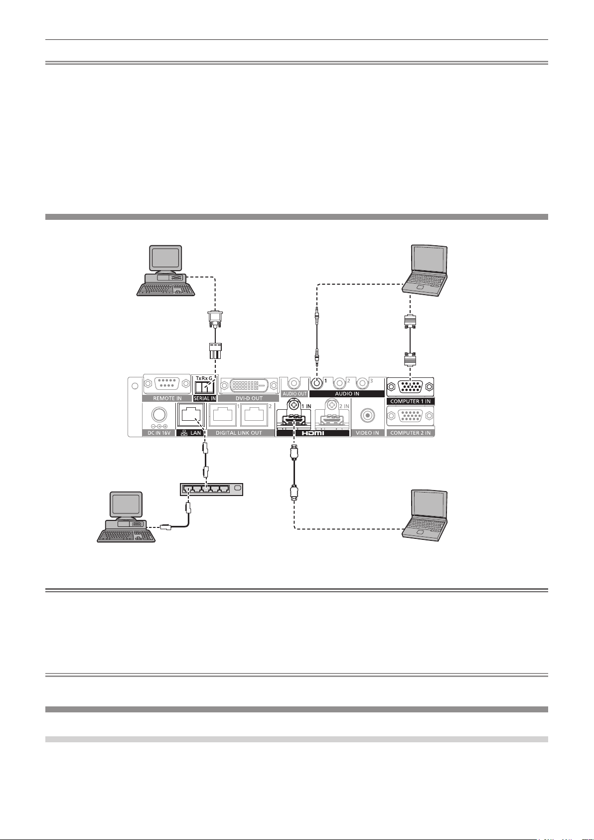
Connecting example: Computers
Control computer
Plug for 3-pin 3.5 mm detachable terminal
*1
block
Computer
Computer cable (commercially
available)
HDMI cable (commercially available)
Hub
Control computer
*1 Controls this device and the display (projector or at panel display) main body.
*1
Computer
Attention
f When connecting this device to a computer or an external device, use the power cord supplied with each device and commercially available
shielded cables.
f Since the <LAN> terminal is very close to the <REMOTE IN> terminal or the <SERIAL IN> terminal, it may be difcult to remove the cable
connected to the <LAN> terminal when a cable is connected to the <REMOTE IN> terminal or the <SERIAL IN> terminal. When removing
the cable connected to the <LAN> terminal, remove the cable connected to the <REMOTE IN> terminal or the <SERIAL IN> terminal in
advance.
Note
f To connect to the <SERIAL IN> terminal, refer to “<SERIAL IN> terminal” (x page 84).
Connecting example: Image display device
When connecting to the DIGITAL LINK compatible display
The DIGITAL LINK compatible display (projector or at panel display) can be connected to the <DIGITAL
LINK OUT 1> terminal and the <DIGITAL LINK OUT 2> terminal of this device. Two displays regardless of the
model can be connected to the <DIGITAL LINK OUT 1> terminal and the <DIGITAL LINK OUT 2> terminal
simultaneously, but the display connected to the <DIGITAL LINK OUT 1> terminal will take priority.
ENGLISH - 25
Page 26

Chapter 2 Getting Started — Connecting
f Operation of this device by the remote control of the display
For details, refer to “Operating with the remote control” (x page 36).
f Displaying the on-screen menu (main menu) of this device by the menu operation on the display main body
For details, refer to “Operating with the remote control” (x page 36).
f Display that becomes a copy source of the EDID (extended display identication data)
For details, refer to “Setting [COMPUTER 2 EDID MODE]” (x page 50) and [HDMI IN] (x page 51).
f Display to become target to automatically match the output resolution
For details, refer to [DIGITAL LINK OUT] (x page 53).
DIGITAL LINK compatible projector
DIGITAL LINK compatible flat panel display
Attention
f Do not use a hub to connect this device with the DIGITAL LINK compatible display (projector or at panel display).
f Ask a qualied technician or your dealer for wiring work of the cable for DIGITAL LINK. The image or audio may be interrupted or disrupted
by not achieving the cable transmission characteristics due to defective work.
f Use the cable conforming to following conditions as the LAN cable between this device and the DIGITAL LINK compatible display (projector
or at panel display).
g Compatible to the CAT5e or a higher standard
g Shield type (including the connector)
g Straight wire connection
g Single wire
f Conrm that the cable specication satises the characteristics of CAT5e or higher by using a cable tester or a cable analyzer when laying
the cable.
When a relay connector is used in the middle, measure in a condition that the relay connector is included.
f To reduce the effect of a noise, install and use the cable between this device and the DIGITAL LINK compatible display (projector or at
panel display) unwound and stretched out.
f Do not pull the cable with a strong force. Moreover, do not bend or fold forcedly.
f Do not bind with other cables, especially the power cable, and keep as much distance from other parallely set cables.
f When connecting with the DIGITAL LINK compatible display (projector or at panel display), open the DIGITAL LINK status menu of these
displays after the cable is laid out, and conrm that the signal quality is -12 dB or less.
f Since the <DVI-D OUT> terminal is very close to the <DIGITAL LINK OUT 1> terminal/<DIGITAL LINK OUT 2> terminal, removing of the
cable connected to the <DIGITAL LINK OUT 1> terminal/<DIGITAL LINK OUT 2> terminal may be difcult when cable is connected to the
<DVI-D OUT> terminal. When removing the cable connected to the <DIGITAL LINK OUT 1> terminal/<DIGITAL LINK OUT 2>, remove the
cable connected to the <DVI-D OUT> terminal.
Note
f Maximum transferable distance is normally 100 m (328'1"). If the display (projector or at panel display) to be connected is supporting the
long reach communication method, it can transfer up to 150 m (492'1"). If the distance exceeds this, image or audio may be interrupted
or error may occur in the LAN communication. Note that the usage exceeding the maximum transferable distance is not covered by the
Panasonic support. Depending on the display to be connected, there may be limit in the signal or the distance that the display can receive.
For details, refer to the Operating Instructions of the display in use.
26 - ENGLISH
Page 27

Chapter 2 Getting Started — Connecting
When performing cascade connection for this device
By connecting the devices with cascade connection (multiple device connection) using the HDMI/DVI conversion
cable, video signal can be output to 3 or more DIGITAL LINK compatible displays (projector or at panel display).
DIGITAL LINK compatible projector
DIGITAL LINK compatible flat panel display
DIGITAL LINK compatible projector
HDMI cable (commercially available)
DIGITAL LINK compatible projector
Blu-ray disc player
Note
f Audio signal can also be output from the <DVI-D OUT> terminal when the device is connected in cascade. Set the [OPTION] menu →
[DVI-D OUT] to [CASCADE]. (x page 54)
f Only the video and audio signals can be received on the display connected to the <DIGITAL LINK OUT 1> terminal/<DIGITAL LINK OUT 2>
terminal of the device that is connected in cascade. Ethernet and serial control signals can only be sent/received via the display connected
to the original cascade connection (rst layer).
f When playing back the same image or the image with audio on multiple displays simultaneously by connecting this device in cascade, the
misalignment of the displayed image or the played back audio may be obvious depending on the viewing or listening position.
Misalignment of the audio can be avoided by using the audio output of one of the connected displays, or output the audio using the <AUDIO
OUT> terminal of one of the device.
General guideline of the misalignment of the image and audio per 1 frame of image when 1 device is added while using 2 or more devices
connected is as follows.
Image Audio
Analog signal 0.5 frames 0.07 frames
Digital signal 0.5 frames 1.2 frames
When connecting to non-DIGITAL LINK compatible display
The non-DIGITAL LINK compatible image display device and this device can be connected in following method.
f Directly connect to the <DVI-D OUT> terminal of the device.
f Connect to the <DIGITAL LINK OUT 1> terminal or the <DIGITAL LINK OUT 2> terminal of the device via
twisted-pair-cable transmitter (receiver) of other manufacturers.
ENGLISH - 27
Page 28

Chapter 2 Getting Started — Connecting
Connecting to the <DVI-D OUT> terminal
Even if it is a non-DIGITAL LINK compatible display (projector or at panel display) or other image display device
such as LCD monitor, image can be displayed by connecting to the <DVI-D OUT> terminal of the device if it is an
image display device supporting the HDMI connection or the DVI-D connection.
LCD monitor
Note
f The <DVI-D OUT> terminal can connect to the HDMI and DVI-D compliant devices. However, this may not properly display as no image is
output on some devices.
Using a twisted-pair-cable transmitter of other manufacturers
When connecting with a Panasonic non-DIGITAL LINK compatible display (projector or at panel display), use a
TM
twisted-pair-cable transmitter (receiver) of other manufacturers based on the HDBaseT
Non-DIGITAL LINK compatible projector
Twisted-pair-cable transmitter
(receiver) of other
manufacturers
*1 Name of the DIGITAL LINK terminal may differ depending on the manufacturer.
*1
HDMI cable (commercially available)
standard.
Attention
f When connecting a display (projector or at panel display) using a twisted-pair-cable transmitter (receiver) of other manufacturers based on
HDBaseTTM standard, do not use another twisted-pair-cable transmitter (receiver) between the original twisted-pair-cable transmitter of other
manufacturers and the display. The image or the audio may be interrupted or disrupted.
f Do not use a hub between this device and the twisted-pair-cable transmitter (receiver).
f Ask a qualied technician or your dealer for wiring work of the cable for DIGITAL LINK. If the work is not properly conducted, the cable
transmission characteristics do not meet, and the images and sounds may be interrupted or become unstable.
f Use the cable conforming to following conditions as the LAN cable between this device and the twisted-pair-cable transmitter (receiver).
g Compatible with CAT5e or higher
g Shielded type (including connectors)
g Straight-through
g Single wire
f Conrm that the cable specication satises the characteristics of CAT5e or higher by using a cable tester or a cable analyzer when laying
the cable.
When a relay connector is used, include it in the measurement.
f To reduce the effect of a noise, install and use the cable between this device and the twisted-pair-cable transmitter (receiver) unwound and
stretched out.
f Do not pull cables forcefully. In addition, do not bend or fold cables unnecessarily.
f Do not bind with other cables, especially the power cable, and keep as much distance from other parallely set cables.
f Since the <DVI-D OUT> terminal is very close to the <DIGITAL LINK OUT 1> terminal/<DIGITAL LINK OUT 2> terminal, removing of the
cable connected to the <DIGITAL LINK OUT 1> terminal/<DIGITAL LINK OUT 2> terminal may be difcult when cable is connected to the
<DVI-D OUT> terminal. When removing the cable connected to the <DIGITAL LINK OUT 1> terminal/<DIGITAL LINK OUT 2>, remove the
cable connected to the <DVI-D OUT> terminal.
28 - ENGLISH
Page 29

Chapter 2 Getting Started — Connecting
Note
f Maximum transferable distance is normally 100 m (328'1"). If the twisted-pair-cable transmitter (receiver) to be connected is supporting the
long reach communication method, it can transfer up to 150 m (492'1"). If the distance exceeds this, image or audio may be interrupted
or error may occur in the LAN communication. Note that the usage exceeding the maximum transferable distance is not covered by the
Panasonic support. Depending on the twisted-pair-cable transmitter (receiver) to be connected, there may be limit in the signal or the
distance that can be received. For details, refer to the Operating Instructions of the twisted-pair-cable transmitter (receiver) in use.
f Following functions cannot be used when the device is connected to non-DIGITAL LINK compatible display (projector or at panel display)
via the twisted-pair-cable transmitter (receiver) based on the HDBaseTTM standard.
g Operation of this device by the remote control of the display
g No signal sleep function
f For information about the twisted-pair-cable transmitters (receivers) of other manufacturers that the operation has been veried with this
device, visit the Panasonic website ((http://panasonic.net/avc/projector/) or (http://panasonic.net/prodisplays/)). Note that the conrmation
of operation for devices of other manufacturers has been performed only with the items set by Panasonic Corporation, and not all the
operations have been veried. For operation or performance problems caused by the devices of other manufacturers, contact the respective
manufacturer.
ENGLISH - 29
Page 30

Chapter 3 Basic Operations
This chapter describes basic operations to start with.
30 - ENGLISH
Page 31

Chapter 3 Basic Operations — Turning on/off the device
Turning on/off the device
Connecting the AC adapter
Conrm that the <POWER> button of the device is in the <OFF> condition before connecting the AC adapter and
the power cord.
For detailed handing of the AC adapter and the power cord, refer to “Read this rst!” (x page 4).
Attaching procedure
<DC IN> terminal
ii)
i)
Fig. 1
i)
(a)
When the plug is connected in horizontal
direction
ii)
When the plug is connected in horizontal
direction
i)
(a)
When the plug is connected in vertical
direction
Fig. 2
ii)
When the plug is connected in vertical
direction
Fig. 3
1) Securely insert the connector of the power cord into the AC adapter, and then securely insert the plug
of the AC adapter into the <DC IN> terminal at the connecting terminal section. (Fig. 1)
2) Attach the supplied AC adapter securing bracket to the device.
i) Hook the tabs (a) of the AC adapter securing bracket to the holes on the bottom of the device (2 locations).
(Fig. 2)
f Turn the plug of the AC adapter vertically or horizontally in accordance to the installation condition.
ii) Attach the bracket so that the plug of the AC adapter is covered, and secure with 1 supplied screw (M3x6).
(Fig. 3)
f Securely tighten the screw.
ENGLISH - 31
Page 32

Chapter 3 Basic Operations — Turning on/off the device
Attention
f Do not attach the power cord and the AC adapter with the front side of the device down.
f Be sure to x the cables connected to the device and the supplied AC adapter nearby such as the legs of the desk to avoid the cable and
AC adapter weights directly applied to the device.
Removing procedure
i)
ii)
Fig. 2Fig. 1
1) Confirm that the <POWER> button of the device is in the <OFF> condition, and then disconnect from
the outlet holding on the power plug.
2) Remove the AC adapter securing bracket. (Fig. 1)
i) Remove the screw securing the AC adapter securing bracket.
ii) Remove the AC adapter securing bracket.
3) Hold the plug of the AC adapter and disconnect from the <DC IN> terminal. (Fig. 2)
Turning on the power of the DIGITAL LINK Switcher
Conrm the connection of the external device before turning on the power.
Power indicator <POWER>
<POWER> button
1) Connect the power plug to an outlet.
2) Press the <POWER> button to turn on the power.
f The power indicator <POWER> will light up.
Note
f When an audio system is used by connecting to the <AUDIO OUT> terminal, a noise may sound from the external audio system when the
power of the device is turned off/on. In this case, turn off/on the device with the sound system turned off.
f If the power indicator <POWER> or the input terminal indicator is blinking, consult your dealer.
Turning off the power of the DIGITAL LINK Switcher
1) Press the <POWER> button to turn off the power.
f The power indicator <POWER> will turn off.
Note
f When an audio system is used by connecting to the <AUDIO OUT> terminal, a noise may sound from the external audio system when the
power of the device is turned off/on. In this case, turn off/on the device with the sound system turned off.
32 - ENGLISH
Page 33

Chapter 3 Basic Operations — Turning on/off the power of the display
Turning on/off the power of the display
The power of the display (projector or at panel display) connected to the <DIGITAL LINK OUT 1> terminal or the
<DIGITAL LINK OUT 2> terminal of the device can be turned off/on with the <DISPLAY DEVICE v/b 1> button or
the <DISPLAY DEVICE v/b 2> button in the control panel of the device.
f The display (projector or at panel display) connected to the <DIGITAL LINK OUT 1> terminal can be operated
with the <DISPLAY DEVICE v/b 1> button. Also, the display connected to the <DIGITAL LINK OUT 2> terminal
can be operated with the <DISPLAY DEVICE v/b 2> button.
Display device indicator <DISPLAY DEVICE>
<DISPLAY DEVICE v/b 1> button/<DISPLAY DEVICE v/b 2> button
Before turning off/on the power of the display
Checking the status of the device
Turn on the power of the device before operating the <DISPLAY DEVICE v/b 1> button/<DISPLAY DEVICE v/b
2> button. (x page 32)
To turn off/on the power of the display, set [(IN)PARITY] of the [OPTION] menu → [RS-232C] (x page 59) to
following.
f To turn off/on the power of the projector
Set in accordance to the parity condition of the serial input terminal of the projector.
f To turn off/on the power of the at panel display
Set to [NONE].
f To turn off/on the power of both the projector and the at panel display
Set to [NONE].
Also set the parity condition of the serial input terminal of the projector to “NONE”.
Checking the display status
The target display is required to be in following conditions to turn off/on the power of the display with the
<DISPLAY DEVICE v/b 1> button/<DISPLAY DEVICE v/b 2> button. For details, refer to the Operating
Instructions of the display in use.
r To turn on the power of the display
f To turn on the power of the projector
g Projector is in standby mode.
g Network function is enabled even when the projector is in standby mode.
g Communication method of DIGITAL LINK is enabled.
g Control for the response is enabled when the “ID ALL” command is received.
f To turn on the power of the at panel display
g Flat panel display is in standby mode.
g Control with the DIGITAL LINK terminal or the LAN terminal is enabled.
g RS-232C communication via the twisted-pair-cable transmitter is enabled.
g Control for the response is enabled when the “ID ALL” command is received.
r To turn off the power of the display
f To turn off the power of the projector
g Power of the projector is turned on (projecting mode).
g Communication method of DIGITAL LINK is enabled.
g Control for the response is enabled when the “ID ALL” command is received.
f To turn off the power of the at panel display
ENGLISH - 33
Page 34

Chapter 3 Basic Operations — Turning on/off the power of the display
g Power of the at panel display is turned on.
g Control with the DIGITAL LINK terminal or the LAN terminal is enabled.
g RS-232C communication via the twisted-pair-cable transmitter is enabled.
g Control for the response is enabled when the “ID ALL” command is received.
Turning on the power of the display
This is the operation to switch the power of the display (projector or at panel display) from standby mode to
power-on condition.
1) Press and hold the <DISPLAY DEVICE v/b 1> button or the <DISPLAY DEVICE v/b 2> button for 3
seconds or longer, and then release the button.
f The power of the display connected to the <DIGITAL LINK OUT 1> terminal or the <DIGITAL LINK OUT 2>
terminal is turned on. The display device indicator <DISPLAY DEVICE> of the corresponding side will light
up after a while.
Note
f It may take up to 30 seconds until the display device indicator <DISPLAY DEVICE> turns on when the power is turned on at the display
main body.
f Press and hold the <DISPLAY DEVICE v/b 1> button or the <DISPLAY DEVICE v/b 2> button for 3 seconds or longer, and release the
button after the display device indicator <DISPLAY DEVICE> is blinking. This button operation will be invalid when the time holding the
button is less than 3 seconds.
f Depending on the status of the connected display, the power of the display cannot be turned off/on with the operation from this device.
Turning off the power of the display
This is the operation to switch the power of the display (projector or at panel display) from power-on condition to
standby mode.
1) Press and hold the <DISPLAY DEVICE v/b 1> button or the <DISPLAY DEVICE v/b 2> button for 3
seconds or longer, and then release the button.
f The power of the display connected to the <DIGITAL LINK OUT 1> terminal or the <DIGITAL LINK OUT 2>
terminal is turned off and go into standby mode. The display device indicator <DISPLAY DEVICE> of the
corresponding side will turn off.
Note
f Press and hold the <DISPLAY DEVICE v/b 1> button or the <DISPLAY DEVICE v/b 2> button for 3 seconds or longer, and release the
button after the display device indicator <DISPLAY DEVICE> is blinking. This button operation will be invalid when the time holding the
button is less than 3 seconds.
f The power of the display connected to the <DIGITAL LINK OUT 1> terminal or the <DIGITAL LINK OUT 2> terminal is not turned off in
conjunction even when the power of this device is turned off. Turn off the power of the display before turning off the power of this device.
f Depending on the status of the connected display, the power of the display cannot be turned off/on with the operation from this device.
34 - ENGLISH
Page 35

Chapter 3 Basic Operations — Checking the image
Checking the image
Conrm the connection of the external equipment (x page 23), connection of the AC adapter (x page 31),
and then turn on the power. (x page 32)
Select an image, and conrm that the selected image is projected from the projector or displayed on the at panel
display.
Selecting the image to display
1) Turn on the power of the image display device and other equipment.
f Conrm that the power of the equipment, such as the projector, at panel display, Blu-ray disc player,
connected to this device is turned on.
2) Select the DIGITAL LINK input with the input selection button on the remote control of the display
(projector or flat panel display), or the input selection button on the display main body.
f Input of the display switches to DIGITAL LINK, and the [INPUT SELECT] menu of this device is displayed.
DIGITAL LINK SWITCHERET-YFB200
INPUT SELECT
PICTURE
POSITION
HDMI 1
HDMI 2
COMPUTER 1
COMPUTER 2
VIDEO
LANGUAGE
OPTION
3) Press the input selection button (<HDMI 1>, <HDMI 2>, <COMPUTER 1>, <COMPUTER 2>, <VIDEO>)
on the control panel.
f The image of the signal being input in the selected terminal is projected or displayed.
f When the DIGITAL LINK compatible display is connected to this device, input of this device can be
switched using the remote control of the display. For details, refer to “Operating with the remote control”
(x page 36).
Attention
f Images may not be displayed properly depending on the external device, or Blu-ray disc or DVD to be played. Set the [PICTURE] menu →
[SYSTEM SELECTOR].
Note
f The on-screen display language is set to English when the power is turned on for the rst time after purchase, or when [USER DATA] in the
[OPTION] menu → [INITIALIZE] is executed.
The display language can be selected from English, German, French, Spanish, and Japanese in the [LANGUAGE] menu.
f It may take approximately 1 minute until the image is projected or displayed depending on the connection environment (signal quality) of the
DIGITAL LINK.
ENGLISH - 35
Page 36

Chapter 3 Basic Operations — Operating with the remote control
Operating with the remote control
This device can be operated with the remote control of the display when the display (projector or at panel
display) is connected to the <DIGITAL LINK OUT 1> terminal/<DIGITAL LINK OUT 2> terminal. Depending on the
remote control, it may not have some buttons or operations may be different.
f The operation may not be possible when the remote control signal receiver of the connected display is under
strong light, such as uorescent lamp. Use it in a place distant from the light source.
f When DIGITAL LINK compatible displays are connected to both <DIGITAL LINK OUT 1> terminal and <DIGITAL
LINK OUT 2> terminal of the device, operation of the device is possible only with the remote control of the
display connected to the <DIGITAL LINK OUT 1> terminal.
Switching the input
Switch the input with the [INPUT SELECT] menu of this device.
ET-YFB200 DIGITAL LINK SWITCHER
INPUT SELECT
HDMI 1
HDMI 2
COMPUTER 1
COMPUTER 2
VIDEO
Switching the input when projector is used
1) Press the DIGITAL LINK button on the remote control.
f Input of the projector will switch to DIGITAL LINK, and the [INPUT SELECT] menu of this device is
displayed.
2) Press as on the remote control to select the input, and press the ENTER button.
f This operation can be also performed by using the DIGITAL LINK button on the remote control. The input is
switched every time the button is pressed.
Switching the input when at panel display is used
It is necessary to assign the input switch to the number button with the function setting of the at panel display
when the remote control of the at panel display is used for the operation.
1) Press the number button of the remote control where the DIGITAL LINK is assigned.
f Input of the at panel display will switch to DIGITAL LINK, and the [INPUT SELECT] menu of this device is
displayed.
2) Press as on the remote control to select the input, and press the ENTER button.
Displaying the on-screen menu (main menu)
Display the on-screen menu (main menu).
DIGITAL LINK SWITCHERET-YFB200
INPUT SELECT
PICTURE
POSITION
HDMI 1
HDMI 2
COMPUTER 1
COMPUTER 2
VIDEO
36 - ENGLISH
LANGUAGE
OPTION
Page 37

Chapter 3 Basic Operations — Operating with the remote control
How to display the on-screen menu (main menu) when the projector is used
1) Press the DIGITAL LINK button on the remote control.
f The [INPUT SELECT] menu of this device is displayed.
2) Press the MENU button or the RETURN button on the remote control.
f On-screen menu (main menu) is displayed.
How to display the on-screen menu (main menu) when the at panel display is used
It is necessary to assign the input switch to the number button with the function setting of the at panel display
main unit when the remote control of the at panel display is used for the operation.
1) Press the number button of the remote control where the DIGITAL LINK is assigned.
f The [INPUT SELECT] menu of this device is displayed.
2) Press the RETURN button on the remote control.
f On-screen menu (main menu) is displayed.
Note
f The on-screen menu (main menu) of this device can be displayed by the menu operation of the display (projector or at panel display)
connected to the <DIGITAL LINK OUT 1> terminal/<DIGITAL LINK OUT 2> terminal of this device. The operation will differ depending on the
model of the display, so refer to the Operating Instruction of the display in use. When displays are connected to both <DIGITAL LINK OUT
1> terminal and the <DIGITAL LINK OUT 2> terminal, displaying of the on-screen menu (main menu) of this device is possible only with the
menu operation of the display connected to the <DIGITAL LINK OUT 1> terminal.
For the operation procedure, refer to the Operating Instructions of the display in use.
f Depending on the model of the display (projector or at panel display) in use, the MENU button or the RETURN button may not be present
on the remote control.
f For detailed operating method of the on-screen menu (main menu) of this device, refer to “Menu navigation” (x page 39).
ENGLISH - 37
Page 38

Chapter 4 Settings
This chapter describes the settings and adjustments you can make using the on-screen menu.
38 - ENGLISH
Page 39

Chapter 4 Settings — Menu navigation
Menu navigation
The on-screen menu (menu screen) is used to perform various settings and adjustments of this device.
Navigating through the menu
Operating procedure
button
1) Press the <MENU> button on the control panel.
f The main menu screen is displayed.
DIGITAL LINK SWITCHERET-YFB200
INPUT SELECT
PICTURE
POSITION
LANGUAGE
HDMI 1
HDMI 2
COMPUTER 1
COMPUTER 2
VIDEO
OPTION
f Operation is possible with the remote control depending on the connected DIGITAL LINK compatible
display (projector or at panel display). For details, refer to “Operating with the remote control”
(x page 36).
2) Press as to select an item from the main menu item.
f The selected item is highlighted in yellow.
f The sub-menu items of the selected main menu are displayed on the right side.
ET-YFB200 DIGITAL LINK SWITCHER
INPUT SELECT
LANGUAGE
PICTURE
POSITION
OPTION
SYSTEM SELECTOR
CLAMP POSITION
DIGITAL CINEMA REALITY
AUTO
+24
3) Press the <ENTER> button.
f The sub-menu items become selectable.
4) Press as to select a sub-menu item, and press qw to change or adjust settings.
f For some items, press qw to display an individual adjustment screen with a bar scale as shown below.
CLAMP POSITION
+24
f A screen to set the detailed setting is displayed by pressing the <ENTER> button for the item with item
name only.
Note
f It returns to the menu screen 1 level higher when the <RETURN> button or the <MENU> button is pressed while the menu screen is
displayed.
f Depending on the model of the display (projector or at panel display) in use, the MENU button or the RETURN button may not be present
on the remote control.
f Some items cannot be adjusted or some functions cannot be used depending on the signal that is input to the device. The menu items that
cannot be adjusted or used are shown in gray characters, and they cannot be selected.
f Some items can be adjusted even if signals are not input.
f Individual adjustment screen is cleared automatically if no operation is performed for approximately 5 seconds.
f For menu items, refer to “Main menu” (x page 40) and “Sub-menu” (x page 40).
ENGLISH - 39
Page 40

Chapter 4 Settings — Menu navigation
f When 3D signal is output from the device, the menu of the device is not displayed. To change the setting of the device, input the 2D signal
or operate without inputting any signal.
f When 3D signal is output from the device, all the setting items in the [PICTURE] menu and the [POSITION] menu are disabled.
f The cursor color depends on the setting in the [OPTION] menu → [ON-SCREEN SETTING] → [OSD DESIGN]. The selected item is
displayed with the yellow cursor by default.
f When the [OPTION] menu → [ON-SCREEN SETTING] → [OSD OUTPUT] is set to [DVI-D/DIGITAL LINK], the menu screen (OSD) is
not displayed on any image display device screen connected to the <DVI-D OUT> terminal or the <DIGITAL LINK OUT 2> terminal if the
connection status is as follows. Operate after turning on the power of the image display device connected to the <DIGITAL LINK OUT 1>
terminal.
g Displays (projector or at panel display) are connected to both the <DIGITAL LINK OUT 1> terminal and the <DIGITAL LINK OUT 2>
terminal.
g Display connected to the <DIGITAL LINK OUT 1> terminal is in standby mode.
If the display connected to the <DIGITAL LINK OUT 1> terminal cannot be turned on due to defect, etc., press and hold the <MENU>
button on the control panel of this device for 3 seconds or longer. The menu screen is forcefully output to the output image of all the output
terminal.
Resetting adjusted values to the factory default
If there is the DEFAULT button on the remote control, the values set and adjusted in the menu item will return to
the factory setting when this button is pressed.
1) Press the DEFAULT button on the remote control.
f The operation varies depending on the displayed screen.
g When the sub-menu screen is displayed
The displayed sub-menu items are restored to the factory default settings.
g When the individual adjustment screen is displayed
Only items during adjustment are restored to the factory default settings.
CLAMP POSITION
+24
Note
f The DEFAULT button may not be present on the remote control depending on the display (projector or at panel display) in use.
f Returning all the values set and adjusted in the menu item is performed with [OPTION] menu → [INITIALIZE] (x page 63).
f The mark above the bar scale in the individual adjustment screen indicates the factory default setting. The position of this mark varies
depending on the selected input signals.
Factory setting
+10
Current adjustment value
Main menu
The following items are in the main menu.
When a main menu item is selected, the screen changes to a sub-menu selection screen.
Main menu item Page
[INPUT SELECT] 40
[PICTURE] 41
[POSITION] 41
[LANGUAGE] 41
[OPTION] 41
Sub-menu
The sub-menu of the selected main menu item is displayed, and you can set and adjust items in the sub-menu.
[INPUT SELECT]
Details (x page 42)
40 - ENGLISH
Page 41

Chapter 4 Settings — Menu navigation
[PICTURE]
Sub-menu item Factory default Page
[SYSTEM SELECTOR] [AUTO] 43
[CLAMP POSITION] [24]
[DIGITAL CINEMA REALITY] [AUTO] 44
*1 Depends on the signal input.
*1
Note
f The factory default settings may vary depending on the picture mode.
f Displaying of sub-menu items and factory default values differ depending on the selected input terminal.
[POSITION]
Sub-menu item Factory default Page
[SHIFT] [0] 45
[CLOCK PHASE] [0] 45
[OVER SCAN] [0]
[ASPECT] [AUTO]
[INPUT RESOLUTION] ― 46
*1
*1
43
46
46
*1 Depends on the signal input.
Note
f Displaying of sub-menu items and factory default values differ depending on the selected input terminal.
[LANGUAGE]
Details (x page 48)
[OPTION]
Sub-menu item Factory default Page
[ON-SCREEN SETTING] ― 49
[COMPUTER IN] ― 49
[HDMI IN] ― 51
[DIGITAL LINK OUT] ― 53
[DVI-D OUT] ― 54
[CLOSED CAPTION SETTING] [OFF] 55
[BACK COLOR] [BLUE] 56
[NO SIGNAL SLEEP] [10MIN.] 56
[AUDIO SETTING] ― 56
[AUTO SETUP] ― 58
[BACKUP INPUT SETTING] [OFF] 58
[RS-232C] ― 59
[NETWORK] ― 61
[STATUS] ― 62
[INITIALIZE] ― 63
ENGLISH - 41
Page 42

Chapter 4 Settings — [INPUT SELECT] menu
[INPUT SELECT] menu
Select [INPUT SELECT] from the main menu in the menu screen, and display the sub-menu.
Refer to “Navigating through the menu” (x page 39) for the operation of the menu screen.
Switching the input
An input terminal for the image can be selected.
f Press as to select the input, and press the <ENTER> button.
[HDMI 1] Switches the input to HDMI 1.
[HDMI 2] Switches the input to HDMI 2.
[COMPUTER 1] Switches the input to COMPUTER 1.
[COMPUTER 2] Switches the input to COMPUTER 2.
[VIDEO] Switches the input to VIDEO.
Note
f When the power of the device is turned on, the input selected at the last time of use is enabled.
f The input is set to [COMPUTER 1] in the factory default setting, or when [USER DATA] in [INITIALIZE] (x page 63) is executed.
42 - ENGLISH
Page 43

Chapter 4 Settings — [PICTURE] menu
[PICTURE] menu
Select [PICTURE] from the main menu, and select the item from the sub-menu.
Refer to “Navigating through the menu” (x page 39) for the operation of the menu screen.
f After selecting the item, press asqw to adjust.
Note
f All the setting items in the [PICTURE] menu are disabled when 3D signal is output from the device.
[SYSTEM SELECTOR]
This device will automatically detect the input signal, but you can set the system method manually when an
unstable signal is input. Set the system method matching the input signal.
1) Press as to select [SYSTEM SELECTOR].
2) Press qw or the <ENTER> button.
f The [SYSTEM SELECTOR] individual adjustment screen is displayed.
3) Press qw to switch system method.
f The system method that can be selected will differ depending on the input signal.
Terminals System method
Select [AUTO], [NTSC], [NTSC4.43], [PAL], [PAL-M], [PAL-N], [SECAM], or [PAL60].
<VIDEO IN> terminal
<COMPUTER 1 IN>
terminal, <COMPUTER 2
IN> terminal
<HDMI 1 IN> terminal,
<HDMI 2 IN> terminal
Set to [AUTO] normally. (Setting [AUTO] will automatically select [NTSC], [NTSC4.43], [PAL], [PAL-M],
[PAL-N], [SECAM], or [PAL60].)
Switch the setting to the signal method for the TV used. The NTSC signal method is used in Japan.
480i, 576i, 576p signal Select from [AUTO], [RGB], or [YC
VGA60, 480p signal Select from [AUTO], [VGA60], [480p], or [480p RGB].
Moving image signal
other than above
480i, 576i, 480p, 576p
signal
Moving image signal
other than above
Select from [AUTO], [RGB], or [YP
Select from [AUTO], [RGB], or [YC
Select from [AUTO], [RGB], or [YP
BCR
BPR
BCR
BPR
].
].
].
].
Note
f For the compatible signals, refer to “Compatible signals” (x page 89).
f This may not function properly for some external devices that are connected.
[CLAMP POSITION]
Adjust the optimal point when the black part of the image is blunt or it has turned green.
1) Press as to select [CLAMP POSITION].
2) Press qw or the <ENTER> button.
f The [CLAMP POSITION] individual adjustment screen is displayed.
3) Press qw to adjust.
Condition Indication of optimal value Range
When the black part is
blunt
When the black part is
green
Note
f Setting value of the [CLAMP POSITION] is reected to all the video signals output from the <DVI-D OUT> terminal and the <DIGITAL
LINK OUT 1> terminal/<DIGITAL LINK OUT 2> terminal. Make adjustment on the image display device connected to each terminal when
individual adjustment for each output terminal is required.
f [CLAMP POSITION] can be adjusted only when a signal is input to the <COMPUTER 1 IN> terminal or the <COMPUTER 2 IN> terminal.
Also, [CLAMP POSITION] can be adjusted when a signal is input to the <COMPUTER 1 IN> terminal and only when the [COMPUTER 1
INPUT SETTING] is set to [RGB/YPBPR] in the [OPTION] menu → [COMPUTER IN] (x page 49).
f Adjustment may not be possible depending on the signal.
The point where bluntness of the black part improves the most is the optimal
value.
The point where the green part becomes black, and the bluntness has
improved is the optimal value.
1 - 255
ENGLISH - 43
Page 44

Chapter 4 Settings — [PICTURE] menu
[DIGITAL CINEMA REALITY]
The vertical resolution is further raised with the cinema process to enhance the picture quality when 576i signal is
input to PAL (or SECAM), and 480i, 1080/50i, or 1080/60i signal is input to NTSC.
1) Press as to select [DIGITAL CINEMA REALITY].
2) Press qw or the <ENTER> button.
f The [DIGITAL CINEMA REALITY] individual adjustment screen is displayed.
3) Press qw to switch items.
f The item is switched every time the button is pressed.
[AUTO] It will automatically detect and performs cinema process.
[OFF] It will not perform cinema process.
[30p FIXED]
[25p FIXED]
During 480i or 1080/60i signal
input
During 576i or 1080/50i signal
input
It will become forced cinema process (2:2 pulldown).
44 - ENGLISH
Page 45

Chapter 4 Settings — [POSITION] menu
[POSITION] menu
Select [POSITION] from the main menu, and select the item from the sub-menu.
Refer to “Navigating through the menu” (x page 39) for the operation of the menu screen.
f After selecting the item, press asqw to adjust.
f Setting value of each item in the [POSITION] is reected to all the video signals output from the <DVI-D OUT>
terminal and the <DIGITAL LINK OUT 1> terminal/<DIGITAL LINK OUT 2> terminal. Make adjustment on
the image display device connected to each terminal when individual adjustment for each output terminal is
required.
Note
f All the setting items in the [POSITION] menu are disabled when 3D signal is output from the device.
[SHIFT]
Adjusts the projected or displayed image position.
f When using a projector, conrm that the relative position of the projector and the screen is correctly installed
before adjusting the image position.
1) Press as to select [SHIFT].
2) Press the <ENTER> button.
f The [SHIFT] individual adjustment screen is displayed.
3) Press asqw to adjust the position.
Orientation Operation Adjustment
Press a.
Vertical (up and down)
adjustment
Press s.
Press w.
Horizontal (right and left)
adjustment
Press q.
The image position moves up.
The image position moves down.
The image position moves to the right.
The image position moves to the left.
[CLOCK PHASE]
Adjust the setting to achieve an optimal image when a ickering or smearing edge appears on the image.
1) Press as to select [CLOCK PHASE].
2) Press qw or the <ENTER> button.
f The [CLOCK PHASE] individual adjustment screen is displayed.
3) Press qw to adjust.
f Adjustment value will change between [0] and [+31]. Adjust so that the amount of interference is at a
minimum.
Note
f Optimal value may not be achieved if the output from the input computer is unstable.
ENGLISH - 45
Page 46

Chapter 4 Settings — [POSITION] menu
f Optimal value may not be achieved when there is a shift in the total dot numbers.
f [CLOCK PHASE] can be adjusted only when the signal is input to the <COMPUTER 1 IN> terminal or the <COMPUTER 2 IN> terminal.
However, [CLOCK PHASE] cannot be selected when Y/C signal, YCBCR signal (480i, 576i), or analog RGB signal (480i, 576i) is input.
f [CLOCK PHASE] cannot be adjusted when video signal or HDMI signal is input.
[OVER SCAN]
f Only when video signal, Y/C signal, YCBCR/YPBPR signal, analog RGB signal (moving image), or HDMI signal
(moving image) is input
Adjust the setting when character or image at the edge of the projected or displayed image is cropped.
1) Press as to select [OVER SCAN].
2) Press qw or the <ENTER> button.
f The [OVER SCAN] individual adjustment screen is displayed.
3) Press qw to adjust.
f Adjustment value is between [0] and [+10].
[ASPECT]
Switch the aspect ratio of the image output from the <DIGITAL LINK OUT 1> terminal, the <DIGITAL LINK OUT
2> terminal, or the <DVI-D OUT> terminal.
1) Press as to select [ASPECT].
2) Press qw or the <ENTER> button.
f The [ASPECT] individual adjustment screen is displayed.
3) Press qw to switch items.
f The item is switched every time the button is pressed.
Aspect mode Description
*1
[AUTO]
[NORMAL]
[WIDE]
*4
[S16:9]
[H FIT]
[V FIT]
[FULL] Outputs the image using all the display valid region of the connected image display device.
[NATIVE] Displays the image in the resolution of the input signals without changing.
*1 Only when video signal (NTSC), Y/C signal (NTSC), YCBCR signal (480i) are input.
*2 Standard signal is a signal with an aspect ratio of 4:3 or 5:4.
*3 Wide signal is a signal with an aspect ratio of 16:10, 16:9, or 15:9.
*4 Only when the wide signal is input.
Recognizes the video ID (VID) embedded in the video signal, and outputs the image by automatically
switching to 4:3 or 16:9 image size.
Maintains the aspect ratio of the input signal and outputs the image so that it is not cropped.
Outputs the image using all the vertical display valid region of the connected image display device
when the standard signal
display valid region of the connected image display device when the wide signal*3 is input.
Outputs the image by converting the aspect ratio to 16:9 or 15:9 when the standard signal
Outputs without changing the aspect ratio of the input when the wide signal*3 is input.
Outputs the image matching 4:3 image size maintaining the aspect ratio when the wide signal*3 is
input.
Outputs the image using all the horizontal display valid region of the connected image display device
maintaining the aspect ratio of the input signal.
Outputs the image using all the vertical display valid region of the connected image display device
maintaining the aspect ratio of the input signal.
*2
is input. Outputs the image using all of either the horizontal or the vertical
*2
is input.
Note
f The image that is actually displayed may not change depending on the input signal even when the [ASPECT] setting is changed.
f The image may look different from the original image when the aspect ratio is set to different one as the one for input signal. Taking care of
this point when setting [ASPECT].
f The copyright of the original copyright owner protected by the copyright laws may be violated when an image is compressed or expanded
using the device at cafe, hotel, etc., for a commercial purpose or public presentation. Take caution when using the function of the device
such as aspect adjustment.
f Part of the peripheral image may not display or be distorted when a conventional (normal) 4:3 image that is not a wide image is projected or
displayed in a wide screen. View the original image respecting the intention of the creator in 4:3 image.
[INPUT RESOLUTION]
Adjust the setting to achieve an optimal image when a ickering or smearing edge appears on the image.
1) Press as to select [INPUT RESOLUTION].
46 - ENGLISH
Page 47

Chapter 4 Settings — [POSITION] menu
2) Press the <ENTER> button.
f The [INPUT RESOLUTION] individual adjustment screen is displayed.
3) Press as to select [TOTAL DOTS], [DISPLAY DOTS], [TOTAL LINES], or [DISPLAY LINES], and press
qw to adjust each item.
f Values corresponding to the input signal are displayed automatically for each item. Increase or decrease
the displayed values and adjust to the optimal condition viewing the screen when there is a vertical banding
or missing in the screen.
Note
f Previously mentioned vertical banding will not occur with all white signal input.
f The image may be disrupted while performing the adjustment, but it is not a malfunction.
f [INPUT RESOLUTION] can be adjusted only when the analog RGB signal is input to the <COMPUTER 1 IN> terminal or the <COMPUTER
2 IN> terminal. Adjustment is not possible when the Y/C signal is input.
f Adjustment may not be possible depending on the signal.
ENGLISH - 47
Page 48

Chapter 4 Settings — [LANGUAGE] menu
[LANGUAGE] menu
On the menu screen, select [LANGUAGE] from the main menu, and display the sub-menu.
Refer to “Navigating through the menu” (x page 39) for the operation of the menu screen.
Changing the display language
Select the language of the on-screen display.
f Press as to select a language, and press the <ENTER> button.
ET-YFB200 DIGITAL LINK SWITCHER
INPUT SELECT
PICTURE
POSITION
LANGUAGE
OPTION
f Various menus, settings, adjustment screens, control button names, etc., are displayed in the selected
language.
f It can be switched to English, German, French, Spanish, or Japanese.
ENGLISH
DEUTSCH
FRANÇAIS
ESPAÑOL
日本語
Note
f The on-screen display language is set to English in the factory default setting, or when [USER DATA] in the [OPTION] menu → [INITIALIZE]
(x page 63) is executed.
48 - ENGLISH
Page 49

Chapter 4 Settings — [OPTION] menu
[OPTION] menu
Select [OPTION] from the main menu, and select the item from the sub-menu.
Refer to “Navigating through the menu” (x page 39) for the operation of the menu screen.
f After selecting the item, press asqw to adjust.
[ON-SCREEN SETTING]
Set the on-screen display.
Setting [OSD DESIGN]
Set the color of the menu screen (OSD).
1) Press as to select [ON-SCREEN SETTING].
2) Press the <ENTER> button.
f The [ON-SCREEN SETTING] screen is displayed.
3) Press as to select [OSD DESIGN].
4) Press qw to switch the item.
f The item is switched every time the button is pressed.
[TYPE1] Sets to blue.
[TYPE2] Sets to black.
Setting [OSD OUTPUT]
Set the terminal to output the menu screen (OSD).
1) Press as to select [ON-SCREEN SETTING].
2) Press the <ENTER> button.
f The [ON-SCREEN SETTING] screen is displayed.
3) Press as to select [OSD OUTPUT].
4) Press qw to switch items.
f The item is switched every time the button is pressed.
[DVI-D/DIGITAL LINK]
[DVI-D] The menu screen (OSD) is displayed only in the output image from the <DVI-D OUT> terminal.
Note
f When the [OSD OUTPUT] is set to [DVI-D/DIGITAL LINK], the menu screen (OSD) is not displayed on any image display device screen
connected to the <DVI-D OUT> terminal or the <DIGITAL LINK OUT 2> terminal if the connection status is as follows. Operate after turning
on the power of the image display device connected to the <DIGITAL LINK OUT 1> terminal.
g Displays (projector or at panel display) are connected to both the <DIGITAL LINK OUT 1> terminal and the <DIGITAL LINK OUT 2>
terminal.
g Display connected to the <DIGITAL LINK OUT 1> terminal is in standby mode.
If the display connected to the <DIGITAL LINK OUT 1> terminal cannot be turned on due to defect, etc., press and hold the <MENU>
button on the control panel of this device for 3 seconds or longer. The menu screen is forcefully output to the output image of all the output
terminal.
f The menu screen (OSD) is not displayed when the 3D signal is output from the device.
The menu screen (OSD) is displayed in the output image from the <DVI-D OUT> terminal, the
<DIGITAL LINK OUT 1> terminal, and the <DIGITAL LINK OUT 2> terminal.
[COMPUTER IN]
Change the setting if the correct image is not displayed when the Y/C signal is input to the device, or when
connected to an external device using the <COMPUTER 1 IN> terminal and the <COMPUTER 2 IN> terminal.
Setting [COMPUTER 1 INPUT SETTING]
Set in accordance to the signal input to the <COMPUTER 1 IN> terminal.
1) Press as to select [COMPUTER IN].
ENGLISH - 49
Page 50

Chapter 4 Settings — [OPTION] menu
2) Press the <ENTER> button.
f The [COMPUTER IN] screen is displayed.
3) Press as to select [COMPUTER 1 INPUT SETTING].
4) Press qw to switch items.
f The item is switched every time the button is pressed.
[RGB/YPBPR]
[Y/C] Select to input the Y/C signal to the <COMPUTER 1 IN> terminal.
Select this when the RGB signal or the YC
terminal.
/YPBPR signal is input to the <COMPUTER 1 IN>
BCR
Note
f When the Y/C signal is to be input to the <COMPUTER 1 IN> terminal, use the optional D-SUB - S Video conversion cable (Model No.:
ET-ADSV).
Switching the slice level of the input synchronization signal
Set in accordance to the signal input to the <COMPUTER 1 IN> terminal and the <COMPUTER 2 IN> terminal.
1) Press as to select [COMPUTER IN].
2) Press the <ENTER> button.
f The [COMPUTER IN] screen is displayed.
3) Press as to select [SYNC SLICE LEVEL].
4) Press qw to switch items.
f The item is switched every time the button is pressed.
[LOW] Sets the slice level to [LOW].
[HIGH] Sets the slice level to [HIGH].
Setting [COMPUTER 2 EDID MODE]
Set the EDID (extended display identication data) of the computer 2 input.
1) Press as to select [COMPUTER IN].
2) Press the <ENTER> button.
f The [COMPUTER IN] screen is displayed.
3) Press as to select [COMPUTER 2 EDID MODE].
4) Press qw to switch items.
f The item is switched every time the button is pressed.
[DEFAULT] This is the default setting.
[COPY]
[USER] Sets the [RESOLUTION] and [VERTICAL SCAN FREQUENCY] items to EDID.
f When [DEFAULT] or [COPY] is selected, advance to Step 13).
5) Press as to select [RESOLUTION].
6) Press the <ENTER> button.
f The [RESOLUTION] screen is displayed.
7) Press as to select [RESOLUTION].
f Select [1024x768p], [1280x720p], [1280x768p], [1280x800p], [1280x1024p], [1366x768p], [1400x1050p],
[1440x900p], [1600x900p], [1600x1200p], [1680x1050p], [1920x1080p], [1920x1080i], or [1920x1200p].
Changes the EDID in accordance with the display (projector or at panel display) connected to the
<DIGITAL LINK OUT 1> terminal or the <DIGITAL LINK OUT 2> terminal.
8) Press the <ENTER> button.
50 - ENGLISH
Page 51

Chapter 4 Settings — [OPTION] menu
9) Press the <RETURN> button.
f The screen returns to the [COMPUTER IN] screen.
10) Press as to select [VERTICAL SCAN FREQUENCY].
11) Press the <ENTER> button.
f The [VERTICAL SCAN FREQUENCY] screen is displayed.
12) Press as to select [VERTICAL SCAN FREQUENCY].
f When [1920x1080p] is selected for [RESOLUTION], select [60Hz], [50Hz], [30Hz], [25Hz], or [24Hz].
f Select [60Hz], [50Hz], or [48Hz] when [1920x1080i] is selected for [RESOLUTION].
f Select [60Hz] or [50Hz] when anything other than [1920x1080p] or [1920x1080i] is selected for
[RESOLUTION].
13) Press the <ENTER> button.
14) Press the <RETURN> button.
f The screen returns to the [COMPUTER IN] screen.
15) Press as to select [STORE], and press the <ENTER> button.
Note
f [COMPLETE] is displayed when the setting is correctly saved, and [INCOMPLETE] is displayed when the setting was not saved.
f The changed settings are displayed in the [RESOLUTION] and [VERTICAL SCAN FREQUENCY] of [EDID STATUS].
f When displays (projector or at panel display) are connected to both the <DIGITAL LINK OUT 1> terminal and the <DIGITAL LINK OUT 2>
terminal of the device, and [COMPUTER 2 EDID MODE] is set to [COPY], EDID is changed in accordance with the display connected to the
<DIGITAL LINK OUT 1> terminal.
f Setting cannot be saved even if [COMPUTER 2 EDID MODE] is set to [COPY] while a display (projector or at panel display) with a
resolution not listed in “Compatible signals” (x page 89) is connected.
f To set [COMPUTER 2 EDID MODE] to [USER], set [RESOLUTION] and [VERTICAL SCAN FREQUENCY] combination referring to
“Compatible signals” (x page 89). Setting cannot be saved when it is set with the combination not listed in “Compatible signals”.
f Setting of the resolution and vertical scanning frequency may also be necessary on the computer or image input device in use.
f It may be necessary to reboot the computer, the image input device, or this device after setting.
f It may not be able to output the image in the set resolution or vertical scanning frequency depending on the computer or the image input
device in use.
f The setting of EDID for the computer 1 input cannot be changed.
[HDMI IN]
Set the EDID (extended display identication data) of the HDMI 2 input. Switch the setting when correct image is
not displayed when it is connected to the external device using the <HDMI 2 IN> terminal.
1) Press as to select [HDMI IN].
2) Press the <ENTER> button.
f The [HDMI IN] screen is displayed.
3) Press as to select [HDMI 2 EDID MODE].
4) Press qw to switch items.
f The item is switched every time the button is pressed.
[DEFAULT] This is the default setting.
[COPY]
[USER] Sets the [RESOLUTION] and [VERTICAL SCAN FREQUENCY] items to EDID.
f When [DEFAULT] or [COPY] is selected, advance to Step 13).
5) Press as to select [RESOLUTION].
6) Press the <ENTER> button.
f The [RESOLUTION] screen is displayed.
Changes the EDID in accordance with the display (projector or at panel display) connected to the
<DIGITAL LINK OUT 1> terminal or the <DIGITAL LINK OUT 2> terminal.
7) Press as to select [RESOLUTION].
f Select [1024x768p], [1280x720p], [1280x768p], [1280x800p], [1280x1024p], [1366x768p], [1400x1050p],
[1440x900p], [1600x900p], [1600x1200p], [1680x1050p], [1920x1080p], [1920x1080i], or [1920x1200p].
ENGLISH - 51
Page 52

Chapter 4 Settings — [OPTION] menu
8) Press the <ENTER> button.
9) Press the <RETURN> button.
f The screen returns to the [HDMI IN] screen.
10) Press as to select [VERTICAL SCAN FREQUENCY].
11) Press the <ENTER> button.
f The [VERTICAL SCAN FREQUENCY] screen is displayed.
12) Press as to select [VERTICAL SCAN FREQUENCY].
f When [1920x1080p] is selected for [RESOLUTION], select [60Hz], [50Hz], [30Hz], [25Hz], or [24Hz].
f Select [60Hz], [50Hz], or [48Hz] when [1920x1080i] is selected for [RESOLUTION].
f Select [60Hz] or [50Hz] when anything other than [1920x1080p] or [1920x1080i] is selected for
[RESOLUTION].
13) Press the <ENTER> button.
14) Press the <RETURN> button.
f The screen returns to the [HDMI IN] screen.
15) Press as to select [STORE], and press the <ENTER> button.
Note
f [COMPLETE] is displayed when the setting is correctly saved, and [INCOMPLETE] is displayed when the setting was not saved.
f The changed settings are displayed in the [RESOLUTION] and [VERTICAL SCAN FREQUENCY] of [EDID STATUS].
f When displays (projector or at panel display) are connected to both the <DIGITAL LINK OUT 1> terminal and the <DIGITAL LINK OUT
2> terminal of the device, and [HDMI 2 EDID MODE] is set to [COPY], EDID is changed in accordance with the display connected to the
<DIGITAL LINK OUT 1> terminal.
f Setting cannot be saved even if [HDMI 2 EDID MODE] is set to [COPY] while a display (projector or at panel display) with a resolution not
listed in “Compatible signals” (x page 89) is connected.
f To set [HDMI 2 EDID MODE] to [USER], set [RESOLUTION] and [VERTICAL SCAN FREQUENCY] combination referring to “Compatible
signals” (x page 89). Setting cannot be saved when it is set with the combination not listed in “Compatible signals”.
f Setting of the resolution and vertical scanning frequency may also be necessary on the computer or image input device in use.
f It may be necessary to reboot the computer, the image input device, or this device after setting.
f It may not be able to output the image in the set resolution or vertical scanning frequency depending on the computer or the image input
device in use.
f The setting of EDID for the HDMI 1 input cannot be changed.
52 - ENGLISH
Page 53

Chapter 4 Settings — [OPTION] menu
[DIGITAL LINK OUT]
Perform the setting of the output signal from the <DIGITAL LINK OUT 1> terminal and the <DIGITAL LINK OUT 2>
terminal.
1) Press as to select [DIGITAL LINK OUT].
2) Press the <ENTER> button.
f The [DIGITAL LINK OUT] screen is displayed.
3) Press as to select [FRAME LOCK].
4) Press qw to switch items.
f The item is switched every time the button is pressed.
[OFF] Disables [FRAME LOCK].
Synchronizes the output signal from the <DIGITAL LINK OUT 1> terminal and the <DIGITAL LINK
OUT 2> terminal with the vertical scanning frequency when a moving image signal is input, preventing
the image from being jumpy due to frame jump.
The output resolution is automatically set by the input signal.
f Image is output with the same resolution as the input signal when 720p signal/1080p signal is input.
720p signal: 720/60p, 720/50p
1080p signal: 1080/24p, 1080/25p, 1080/30p, 1080/60p, 1080/50p
[ON]
f Image is output with the resolution of 1 920 x 1 080 dots when a video signal other than the 720p
signal/1080p signal is input.
Target signal: NTSC/NTSC4.43/PAL-M/PAL60, PAL/PAL-N/SECAM, 480i, 576i, 480p, 576p,
1080/60i, 1080/50i
f Image is output by automatically adjusting to the resolution of the display (projector or at panel
display) connected to the <DIGITAL LINK OUT 1> terminal or the <DIGITAL LINK OUT 2> terminal
when a still image signal is input. However, if the resolution of the display cannot be determined,
the image is output in resolution of 1 920 x 1 080 dots.
f When [OFF] is selected, advance to Step 5).
5) Press as to select [OUTPUT RESOLUTION].
6) Press the <ENTER> button.
f The [OUTPUT RESOLUTION] screen is displayed.
7) Press as to switch items.
f The item is switched every time the button is pressed.
[AUTO]
[1920x1200] Outputs the image in 1 920 x 1 200 dots.
[1920x1080] Outputs the image in 1 920 x 1 080 dots.
[1400x1050] Outputs the image in 1 400 x 1 050 dots.
[1366x768] Outputs the image in 1 366 x 768 dots.
[1280x800] Outputs the image in 1 280 x 800 dots.
[1024x768] Outputs the image in 1 024 x 768 dots.
Outputs the image by automatically adjusting to the resolution of the display (projector or at panel
display) connected to the <DIGITAL LINK OUT 1> terminal or the <DIGITAL LINK OUT 2> terminal.
Note
f Image may not display depending on the connected image display device when [OUTPUT RESOLUTION] is set to anything other than
[AUTO]. In such case, press the <RETURN> button on the control panel 4 times, and then press the <ENTER> button and the <RETURN>
button simultaneously to forcefully change [OUTPUT RESOLUTION] to [AUTO] for both [DIGITAL LINK OUT] and [DVI-D OUT].
f Image is output with appropriate resolution and tone for the connected display when [FRAME LOCK] is set to [ON], but it may take some
time for the image to be output at the time of switching the input or switching the signal.
f To output the 3D signal, set [FRAME LOCK] to [ON]. 3D signal is not output when set to [OFF].
f [OUTPUT RESOLUTION] cannot be set when [FRAME LOCK] is set to [ON].
f When the displays are connected to both the <DIGITAL LINK OUT 1> terminal and the <DIGITAL LINK OUT 2> terminal, and [FRAME
LOCK] is set to [ON] to input the still image signal, the image is output matching the resolution of the display connected to the <DIGITAL
LINK OUT 1> terminal.
f When the displays (projector or at panel display) are connected to both the <DIGITAL LINK OUT 1> terminal and the <DIGITAL LINK
OUT 2> terminal of the device and [OUTPUT RESOLUTION] is set to [AUTO], the image is output matching the resolution of the display
connected to the <DIGITAL LINK OUT 1> terminal.
f When [FRAME LOCK] is set to [ON], the [OPTION] menu → [BACKUP INPUT SETTING] (x page 58) cannot be set.
ENGLISH - 53
Page 54

Chapter 4 Settings — [OPTION] menu
[DVI-D OUT]
Perform the setting of the output signal from the <DVI-D OUT> terminal.
1) Press as to select [DVI-D OUT].
2) Press the <ENTER> button.
f The [DVI-D OUT] screen is displayed.
3) Press as to select [FRAME LOCK].
4) Press qw to switch items.
f The item is switched every time the button is pressed.
[OFF] Disables [FRAME LOCK].
Synchronizes the output signal from the <DVI-D OUT> terminal with the vertical scanning frequency
when a moving image signal is input, preventing the image from being jumpy due to frame jump.
The output resolution is automatically set by the input signal.
f Image is output with the same resolution as the input signal when 720p signal/1080p signal is input.
720p signal: 720/60p, 720/50p
1080p signal: 1080/24p, 1080/25p, 1080/30p, 1080/60p, 1080/50p
[ON]
f Image is output with the resolution of 1 920 x 1 080 dots when a moving image signal other than
the 720p signal/1080p signal is input.
Target signal: NTSC/NTSC4.43/PAL-M/PAL60, PAL/PAL-N/SECAM, 480i, 576i, 480p, 576p,
1080/60i, 1080/50i
f Image is output by automatically adjusting to the resolution of the image display device connected
to the <DVI-D OUT> terminal when a still image signal is input. However, if the resolution of the
image display device cannot be determined, the image is output in resolution of 1 920 x 1 080 dots.
f When [OFF] is selected, advance to Step 5).
5) Press as to select [OUTPUT RESOLUTION].
6) Press the <ENTER> button.
f The [OUTPUT RESOLUTION] screen is displayed.
7) Press as to switch items.
f The item is switched every time the button is pressed.
[AUTO]
[1920x1200] Outputs the image in 1 920 x 1 200 dots.
[1920x1080] Outputs the image in 1 920 x 1 080 dots.
[1400x1050] Outputs the image in 1 400 x 1 050 dots.
[1366x768] Outputs the image in 1 366 x 768 dots.
[1280x800] Outputs the image in 1 280 x 800 dots.
[1024x768] Outputs the image in 1 024 x 768 dots.
Outputs the image by automatically adjusting to the resolution of the image display device connected
to the <DVI-D OUT> terminal.
Note
f Image may not be displayed depending on the connected image display device when [OUTPUT RESOLUTION] is set to anything other than
[AUTO]. In such case, press the <RETURN> button on the control panel 4 times, and then press the <ENTER> button and the <RETURN>
button simultaneously to forcefully change [OUTPUT RESOLUTION] to [AUTO] for both [DVI-D OUT] and [DIGITAL LINK OUT].
f Image is output with appropriate resolution and tone for the connected image display device when [FRAME LOCK] is set to [ON], but it may
take some time for the image to be output at the time of switching the input or switching the signal.
f [OUTPUT RESOLUTION] cannot be set when [FRAME LOCK] is set to [ON].
f The <DVI-D OUT> terminal does not support the output of 3D signal.
f When [FRAME LOCK] is set to [ON], the [OPTION] menu → [BACKUP INPUT SETTING] (x page 58) cannot be set.
Setting the audio output for cascade connection
Set the audio signal output from the <DVI-D OUT> terminal when cascade connection (multiple device
connection) is performed with the device.
The [CASCADE] setting is enabled when [AUDIO OUT SELECT] is set to [DIGITAL LINK].
1) Press as to select [DVI-D OUT].
54 - ENGLISH
Page 55

Chapter 4 Settings — [OPTION] menu
2) Press the <ENTER> button.
f The [DVI-D OUT] screen is displayed.
3) Press as to select [CASCADE].
4) Press qw to switch items.
f The item is switched every time the button is pressed.
[OFF] Does not output the audio signal from the <DVI-D OUT> terminal.
[ON] Outputs the audio signal superimposed on the video signal from the <DVI-D OUT> terminal.
Note
f When [CASCADE] is set to [ON], the audio from the audio input set in [AUDIO IN SELECT] is output. For details, refer to [AUDIO SETTING]
(x page 56).
f When playing back the same image with audio on multiple displays (projector or at panel display) simultaneously by connecting this device
in cascade, the misalignment of the played back audio may be obvious depending on the viewing or listening position. For details, refer to
“When performing cascade connection for this device” (x page 27).
[CLOSED CAPTION SETTING] (only when NTSC or 480i YCBCR signal is input)
Set closed captions.
Selecting to display the closed caption
1) Press as to select [CLOSED CAPTION SETTING].
2) Press the <ENTER> button.
f The [CLOSED CAPTION SETTING] screen is displayed.
3) Press as to select [CLOSED CAPTION].
4) Press qw to switch items.
f The item is switched every time the button is pressed.
[OFF] Hides closed captions.
[ON] Displays closed captions.
Setting the closed caption mode
1) Press as to select [CLOSED CAPTION SETTING].
2) Press the <ENTER> button.
f The [CLOSED CAPTION SETTING] screen is displayed.
3) Press as to select [MODE].
f When [CLOSED CAPTION] is set to [OFF], [MODE] cannot be selected.
4) Press qw to switch items.
f The item is switched every time the button is pressed.
[CC1] Displays CC1 data.
[CC2] Displays CC2 data.
[CC3] Displays CC3 data.
[CC4] Displays CC4 data.
Note
f Closed caption is a function that displays text information of video signals mainly used in North America. Captions may not be displayed
depending on the connected devices or contents being played back.
f [CLOSED CAPTION SETTING] can be selected only when NTSC, 480i YCBCR signal is input.
f Closed captions are not displayed when the menu screen is displayed.
ENGLISH - 55
Page 56

Chapter 4 Settings — [OPTION] menu
[BACK COLOR]
The color of the output image when the video signal is not input in the selected input terminal is set.
1) Press as to select [BACK COLOR].
2) Press qw to switch the item.
f The item is switched every time the button is pressed.
[BLUE] Outputs a video signal with blue on full area.
[BLACK] Outputs a video signal with black on full area.
[NO SIGNAL SLEEP]
This is a function to automatically stop the output of a signal from the <DIGITAL LINK OUT 1> terminal/<DIGITAL
LINK OUT 2> terminal and the <DVI-D OUT> terminal when no video signal is input into the selected input
terminal continuously. The time until the signal output is stopped can be set.
By enabling this function, the power consumption of this device can be reduced, and the power save function of
the connected image display device can also be utilized.
1) Press as to select [NO SIGNAL SLEEP].
2) Press qw to switch the item.
f The item is switched every time the button is pressed.
[10MIN.] Stops output of the signal when no signal is input for 10 minutes.
[20MIN.] Stops output of the signal when no signal is input for 20 minutes.
[30MIN.] Stops output of the signal when no signal is input for 30 minutes.
[OFF] Disables [NO SIGNAL SLEEP].
Note
f The signal output is resumed in following cases.
g When a video signal is input to the selected input terminal while the signal is stopped.
g When the button on the control panel is operated.
g When the operation to display the on-screen menu of the device is performed.
f To transfer the user logo to the projector by using the Logo Transfer Software, turn this function to [OFF] before transferring. When the
output is stopped for longer than the set time, the communication will be shut down and the user logo may not be transferred properly.
f Regardless of the setting of [NO SIGNAL SLEEP], output of the audio corresponding to the input will stop when the video signal for the
selected input terminal stops.
[AUDIO SETTING]
Set the details of the sound function.
Adjusting volume
Adjust the volume output from the <AUDIO OUT> terminal.
1) Press as to select [AUDIO SETTING].
2) Press the <ENTER> button.
f The [AUDIO SETTING] screen is displayed.
3) Press as to select [VOLUME].
4) Press qw to adjust the level.
Operation Adjustment Range
Press w.
Press q.
Increases the volume.
Decreases the volume.
Note
f When [AUDIO OUT SELECT] is set to [OFF] or [DIGITAL LINK], [VOLUME] cannot be adjusted.
56 - ENGLISH
0 - 63
Page 57

Chapter 4 Settings — [OPTION] menu
Adjusting the audio balance
Adjust the balance of the audio output from the <AUDIO OUT> terminal.
1) Press as to select [AUDIO SETTING].
2) Press the <ENTER> button.
f The [AUDIO SETTING] screen is displayed.
3) Press as to select [BALANCE].
4) Press qw to adjust the level.
Operation Adjustment Range
Press w.
Press q.
Increases the volume for right side.
Increases the volume for left side.
Note
f When [AUDIO OUT SELECT] is set to [OFF] or [DIGITAL LINK], [BALANCE] cannot be adjusted.
Setting the output of audio
Set the terminal to output the audio signal.
L16 - R16
1) Press as to select [AUDIO SETTING].
2) Press the <ENTER> button.
f The [AUDIO SETTING] screen is displayed.
3) Press as to select [AUDIO OUT SELECT].
4) Press qw to switch items.
f The item is switched every time the button is pressed.
[DIGITAL LINK]
[AUDIO OUT] Outputs the audio signal from the <AUDIO OUT> terminal.
[OFF] Does not output the audio signal.
Outputs the audio signal from the <DIGITAL LINK OUT 1> terminal and the <DIGITAL LINK OUT 2>
terminal.
Note
f The audio signal cannot be output from both the <DIGITAL LINK OUT 1> terminal/<DIGITAL LINK OUT 2> terminal and the <AUDIO OUT>
terminal.
Setting the source of audio
Set the audio input for each video input terminal.
1) Press as to select [AUDIO SETTING].
2) Press the <ENTER> button.
f The [AUDIO SETTING] screen is displayed.
3) Press as to select [AUDIO IN SELECT].
4) Press the <ENTER> button.
f The [AUDIO IN SELECT] screen is displayed.
5) Press as to select the audio input.
f Select from [HDMI 1], [HDMI 2], [COMPUTER 1], [COMPUTER 2], or [VIDEO].
6) Press qw to switch items.
f The item is switched every time the button is pressed.
Outputs the audio from the <HDMI 1 IN> terminal when a video signal is input to the selected input
[HDMI 1 AUDIO IN]
terminal.
f This is displayed only when [HDMI 1] is selected in Step 5).
ENGLISH - 57
Page 58

Chapter 4 Settings — [OPTION] menu
Outputs the audio from the <HDMI 2 IN> terminal when a video signal is input to the selected input
[HDMI 2 AUDIO IN]
[AUDIO IN 1]
[AUDIO IN 2]
[AUDIO IN 3]
[OFF] Does not output the audio.
terminal.
f This is displayed only when [HDMI 2] is selected in Step 5).
Outputs the audio from the <AUDIO IN 1> terminal when a video signal is input to the selected input
terminal.
Outputs the audio from the <AUDIO IN 2> terminal when a video signal is input to the selected input
terminal.
Outputs the audio from the <AUDIO IN 3> terminal when a video signal is input to the selected input
terminal.
Note
f Audio is output only when a video signal is input to the selected input terminal.
[AUTO SETUP]
Set the operation of the automatic setup function.
When the automatic setup function is operated, image position, clock phase, or resolution when the analog RGB
signal that is constructed with dots such as the computer signal is input, or the image position when the HDMI
signal is input is automatically adjusted.
1) Press as to select [AUTO SETUP].
2) Press the <ENTER> button.
f The [AUTO SETUP] screen is displayed.
3) Press as to select [AUTO SETUP SETTING].
4) Press qw to switch the item.
f The item is switched every time the button is pressed.
[MANUAL] Manually operates the automatic setup function.
[AUTO] Automatically operates the automatic setup function when the input signal is switched.
f When [MANUAL] is selected, advance to Step 5).
5) Press as to select [AUTO SETUP], and press the <ENTER> button.
f Automatic setup function will operate.
Note
f This function operates only when analog RGB signal (still image) or HDMI signal (still image and moving image) is input.
f When the automatic setup function is to be operated by setting [MANUAL], it is recommended to input an image with bright white border at
the edges and include black and white characters that are high in contrast. Image such as photograph or computer graphic with halftone is
not appropriate.
[BACKUP INPUT SETTING]
Set the backup function to automatically switch the signal from the backup input when input signal is disrupted.
1) Press as to select [BACKUP INPUT SETTING].
2) Press the <ENTER> button.
f The [BACKUP INPUT SETTING] screen is displayed.
3) Press as to select [BACKUP INPUT MODE].
4) Press qw to switch items.
f The item is switched every time the button is pressed.
[OFF] Disables the backup function.
Enables the backup function and switches to the secondary input automatically when the input signal
[1]
for primary input is disrupted.
Primary input is xed to the <HDMI 1 IN> terminal, and the secondary input is xed to the <HDMI 2
IN> terminal.
58 - ENGLISH
Page 59

Chapter 4 Settings — [OPTION] menu
Enables the backup function and switches to the secondary input automatically when the input signal
[2]
for primary input is disrupted.
Primary input is xed to the <HDMI 2 IN> terminal, and the secondary input is xed to the <HDMI 1
IN> terminal.
Note
f To switch to the backup input (secondary input) signal using the backup function, fullling of the following 3 conditions are required to use
the function.
g Set [BACKUP INPUT MODE] to [1] or [2].
g Input the same signal to the primary and secondary inputs.
g Select primary input.
f When the input is automatically switched to the secondary input with the backup function, the current input (secondary input) will be
maintained even when the primary input signal is restored.
f [BACKUP INPUT SETTING] cannot be set when the [OPTION] menu → [DIGITAL LINK OUT] (x page 53) → [FRAME LOCK] is set to
[ON], or when the [OPTION] menu → [DVI-D OUT] (x page 54) → [FRAME LOCK] is set to [ON]. The backup operation is not performed.
[RS-232C]
Set the ID number of the device, and communication condition of the <SERIAL IN> terminal and the <DIGITAL
LINK OUT 1> terminal/<DIGITAL LINK OUT 2> terminal.
For the connection example of the display (projector or at panel display), communication cable specication, and
control command, refer to “<SERIAL IN> terminal” (x page 84).
Setting [ID]
Set the ID number of the device.
When the system is made up of multiple devices, such as connecting the display (projector or at panel display)
via the <DIGITAL LINK OUT 1> terminal/<DIGITAL LINK OUT 2> terminal of this device, controlling with each ID
number from a single computer is possible by setting individual/shared ID number.
1) Press as to select [RS-232C].
2) Press the <ENTER> button.
f The [RS-232C] screen is displayed.
3) Press as to select [ID].
4) Press qw to switch items.
f The item is switched every time the button is pressed.
[1] - [6] Select the ID number.
Setting [(IN)BAUDRATE]
Sets the communication speed of the <SERIAL IN> terminal.
1) Press as to select [RS-232C].
2) Press the <ENTER> button.
f The [RS-232C] screen is displayed.
3) Press as to select [(IN)BAUDRATE].
4) Press qw to switch items.
f The item is switched every time the button is pressed.
[9600]
Select the appropriate speed.[19200]
[38400]
Setting [(IN)PARITY]
Set the parity of the <SERIAL IN> terminal.
1) Press as to select [RS-232C].
ENGLISH - 59
Page 60

Chapter 4 Settings — [OPTION] menu
2) Press the <ENTER> button.
f The [RS-232C] screen is displayed.
3) Press as to select [(IN)PARITY].
4) Press qw to switch items.
f The item is switched every time the button is pressed.
[NONE]
Sets the condition of parity.[EVEN]
[ODD]
Setting [(OUT)PARITY]
Set the communication condition for the <DIGITAL LINK OUT 1> terminal and the <DIGITAL LINK OUT 2>
terminal.
1) Press as to select [RS-232C].
2) Press the <ENTER> button.
f The [RS-232C] screen is displayed.
3) Press as to select [(OUT)PARITY].
4) Press qw to switch items.
f The item is switched every time the button is pressed.
[NONE]
Select the parity condition.[EVEN]
[ODD]
Note
f The parity settings for the <DIGITAL LINK OUT 1> terminal and the <DIGITAL LINK OUT 2> terminal are shared. Also check the
communication condition (parity setting) of the serial terminal for the display connecting to each terminal.
Setting [RESPONSE(ID ALL)]
Set the response of this device when the “ID ALL” command is received.
1) Press as to select [RS-232C].
2) Press the <ENTER> button.
f The [RS-232C] screen is displayed.
3) Press as to select [RESPONSE(ID ALL)].
4) Press qw to switch items.
f The item is switched every time the button is pressed.
[OFF] Does not return the response when the “ID ALL” command is received.
[ON] Returns the response when the “ID ALL” command is received.
Setting [CONTROL(ID ALL)]
Set the control of this device when the “ID ALL” command is received.
1) Press as to select [RS-232C].
2) Press the <ENTER> button.
f The [RS-232C] screen is displayed.
3) Press as to select [CONTROL(ID ALL)].
4) Press qw to switch items.
f The item is switched every time the button is pressed.
60 - ENGLISH
Page 61

Chapter 4 Settings — [OPTION] menu
[DISABLE] Does not control the device by command when the “ID ALL” command is received.
[ENABLE] Controls the device by command when the “ID ALL” command is received.
Setting [GROUP]
Set the group of this device. Control of the device by command is performed when the ID designation in the
command matches.
When the system is made up of multiple devices, such as connecting the display (projector or at panel display)
via the <DIGITAL LINK OUT 1> terminal/<DIGITAL LINK OUT 2> terminal of this device, devices in the same
group can be controlled simultaneously.
1) Press as to select [RS-232C].
2) Press the <ENTER> button.
f The [RS-232C] screen is displayed.
3) Press as to select [GROUP].
4) Press qw to switch items.
f The item is switched every time the button is pressed.
[A] - [Z] Select the group.
Setting [RESPONSE(GROUP)]
Set the control of this device when the “ID GROUP” command is received.
1) Press as to select [RS-232C].
2) Press the <ENTER> button.
f The [RS-232C] screen is displayed.
3) Press as to select [RESPONSE(GROUP)].
4) Press qw to switch items.
f The item is switched every time the button is pressed.
[ON] Returns the response when the “ID GROUP” command is received.
[OFF] Does not return the response when the “ID GROUP” command is received.
[NETWORK]
Perform the setting of the network function.
Setting [NETWORK SETUP]
Perform the initial setting of the network before using the network function.
1) Press as to select [NETWORK].
2) Press the <ENTER> button.
f The [NETWORK] screen is displayed.
3) Press as to select [NETWORK SETUP].
4) Press the <ENTER> button.
f The [NETWORK SETUP] screen is displayed.
5) Press as to select each item, and change the setting following the instruction of the menu.
[ON]
[DHCP]
[OFF]
[IP ADDRESS] Enter the IP address when a DHCP server is not used.
Automatically acquires an IP address when a DHCP server exists in
the network connected by the <LAN> terminal of this device.
Perform the [IP ADDRESS], the [SUBNET MASK], and the
[DEFAULT GATEWAY] settings when a DHCP server does not exist
in the network connected by the <LAN> terminal of this device.
ENGLISH - 61
Page 62

Chapter 4 Settings — [OPTION] menu
[SUBNET MASK] Enter the subnet mask when a DHCP server is not used.
[DEFAULT GATEWAY] Enter the default gateway address when a DHCP server is not used.
[STORE] Saves the current network setting.
6) Press as to select [STORE], and press the <ENTER> button.
Note
f If a DHCP server is to be used, conrm that the DHCP server is running.
f Check with the network administrator for the IP address, subnet mask, and default gateway.
Setting [NETWORK CONTROL]
Set the control method of the network.
1) Press as to select [NETWORK].
2) Press the <ENTER> button.
f The [NETWORK] screen is displayed.
3) Press as to select [NETWORK CONTROL].
4) Press the <ENTER> button.
f The [NETWORK CONTROL] screen is displayed.
5) Press as to select each item, and press qw to change the setting.
To use the web control, and to use the browser remote control, set to [ON].
[WEB CONTROL]
[PJLink CONTROL] Set to [ON] to control with the PJLink protocol.
[COMMAND CONTROL]
[COMMAND PORT] Sets the port number to use with the command control.
[STORE] Saves the current network control setting.
For details, refer to “Using the web control function” (x page 67), “Using the browser remote
control” (x page 74).
Set to [ON] to control with control command format (x page 87) of the <SERIAL IN> terminal.
For details, refer to “Control commands via LAN” (x page 81).
6) Press as to select [STORE], and press the <ENTER> button.
Displaying [NETWORK STATUS]
Display the network status of the device.
1) Press as to select [NETWORK].
2) Press the <ENTER> button.
f The [NETWORK] screen is displayed.
3) Press as to select [NETWORK STATUS].
4) Press the <ENTER> button.
f The [NETWORK STATUS] screen is displayed.
[DHCP] Displays the usage status of the DHCP server.
[IP ADDRESS] Displays [IP ADDRESS].
[SUBNET MASK] Displays [SUBNET MASK].
[DEFAULT GATEWAY] Displays [DEFAULT GATEWAY].
[DNS1] Displays the address of the preferred DNS server.
[DNS2] Displays the address of the alternate DNS server.
[MAC ADDRESS] Displays [MAC ADDRESS].
[STATUS]
Display the status of the device.
1) Press as to select [STATUS].
62 - ENGLISH
Page 63

2) Press the <ENTER> button.
f The [STATUS] screen is displayed.
Chapter 4 Settings — [OPTION] menu
[INPUT SIGNAL]
[OUTPUT SIGNAL]
[SERIAL NUMBER] [ET-YFB200] Displays the serial number of the device.
[NAME] Displays the input signal name.
[FREQUENCY] Displays the frequency of the input signal.
[NAME] Displays the output signal name.
[FREQUENCY] Displays the frequency of the output signal.
[INITIALIZE]
Return various setting values to their factory default settings.
After executing this operation, turn off and then turn on the <POWER> button of the device.
1) Press as to select [INITIALIZE].
2) Press the <ENTER> button.
f The [INITIALIZE] screen is displayed.
3) Press as to select the item to initialize.
[USER DATA] Returns various setting values to their factory default settings except [NETWORK SETUP].
[NETWORK] Returns [NETWORK SETUP] to the factory setting.
4) Press the <ENTER> button.
f A message [To do the initialization, the unit will need to be turned off.] is displayed.
5) Press qw to select [OK], and press the <ENTER> button.
f [Please turn off the DIGITAL LINK switcher, then turn it back on again.] is displayed.
6) Press the <POWER> button to turn off the power.
7) Press the <POWER> button again to turn on the power.
f All input terminal indicators will light up during the initialization. Wait until all input terminal indicators other
than the selected input terminal turn off.
For the details regarding input terminal indicator, refer to “Control panel” (x page 18).
Note
f Input is set to COMPUTER 1 when [USER DATA] is executed.
ENGLISH - 63
Page 64

Chapter 5 Network control
function
This chapter describes the network control function.
64 - ENGLISH
Page 65

Chapter 5 Network control function — Network connection
Network connection
This device is equipped with a network function, and following are possible by connecting with a computer.
f Web control
Setting, adjustment, and status display of this device are possible by accessing this device from a computer. For
details, refer to “Using the web control function” (x page 67).
f Browser remote control
This device can be operated with the operation panel displayed on the web browser. For details, refer to “Using
the browser remote control” (x page 74).
f PJLink
Operation or status query of this device is possible from the computer using the PJLink protocol. For details,
refer to “PJLink protocol” (x page 80).
f Command control
Operation or status query of this device is possible from the computer using the control command. For details,
refer to “Control commands via LAN” (x page 81).
This device is equipped with a function to send the Ethernet signal via LAN cable together with video and audio
signals to the DIGITAL LINK compatible display (projector or at panel display).
For details, refer to “DIGITAL LINK” (x page 14), “When performing cascade connection for this device”
(x page 27).
Note
f A web browser is required to use the web control function and the browser remote control. Conrm beforehand that the web browser can be
used.
OS Supported browser
Windows Internet Explorer 8.0/9.0/10.0/11.0
Mac OS Safari 6.0/7.0/8.0
f Illustration of the computer screen
The description in this document is using “Windows 7” as the OS, and “Internet Explorer 8.0” as the browser. The size or display of the
screen may differ depending on the OS, browser, or the type of the computer in use.
Connection example
Control computer
LAN cable (straight)
*1
DIGITAL LINK compatible projector
LAN cable (straight)LAN cable (straight)
Hub
*1 Controls this device and the display (projector or at panel display).
Attention
f Wire the LAN cable, which is directly connected to this device, only indoors.
f Do not use a hub to connect this device with the DIGITAL LINK compatible display (projector or at panel display).
f Ask a qualied technician or your dealer for wiring work of the cable for DIGITAL LINK. The image or audio may be interrupted or disrupted
by not achieving the cable transmission characteristics due to defective work.
f Use the cable conforming to following conditions as the LAN cable between this device and the DIGITAL LINK compatible display (projector
or at panel display).
g Conforming to the CAT5e or a higher standard
g Shielded type (including connectors)
g Straight wire
g Single wire
ENGLISH - 65
Page 66

Chapter 5 Network control function — Network connection
f Conrm that the cable specication satises the characteristics of CAT5e or higher by using a cable tester or a cable analyzer when laying
the cable.
When a relay connector is used, include it in the measurement.
f To reduce the effect of a noise, install and use the cable between this device and the DIGITAL LINK compatible display (projector or at
panel display) unwound and stretched out.
f Do not pull the cable with excessive force. Also, do not bend or fold the cable forcefully.
f Do not bind with other cables, especially the power cable, and keep as much distance from other parallely set cables.
f When connecting with the DIGITAL LINK compatible display (projector or at panel display), open the DIGITAL LINK status menu of these
displays after the cable is laid out, and conrm that the signal quality is -12 dB or less.
Note
f Maximum transferable distance is normally 100 m (328'1"). If the display (projector or at panel display) to be connected is supporting the
long reach communication method, it can transfer up to 150 m (492'1"). If the distance exceeds this, image or audio may be interrupted
or error may occur in the LAN communication. Note that the usage exceeding the maximum transferable distance is not covered by the
Panasonic support. Depending on the display to be connected, there may be limit in the signal or the distance that the display can receive.
For details, refer to the Operating Instructions of the display in use.
Setting of the device
1) Connect the device with a computer via LAN cable.
2) Turn on the power of the device.
3) Press the <MENU> button to open the [NETWORK] menu, and perform the [NETWORK SETUP]
setting.
f For details, refer to “Setting [NETWORK SETUP]” (x page 61).
Note
f To connect to an existing network, conrm with the network administrator rst.
f The factory default setting is as follows:
[DHCP] OFF
[IP ADDRESS] 192.168.0.10
[SUBNET MASK] 255.255.255.0
[DEFAULT GATEWAY] 192.168.0.1
[DNS1]/[DNS2] None
Setting of the computer
1) Turn on the power of the computer.
2) Follow the instruction of the network administrator to perform the network setting.
f If this device is in the factory setting condition, it can be used as is when the network settings on the
computer are set as follows.
[IP ADDRESS] 192.168.0.101
[SUBNET MASK] 255.255.255.0
[DEFAULT GATEWAY] 192.168.0.1
Note
f To connect the DIGITAL LINK compatible displays (projector or at panel display) to the <DIGITAL LINK OUT 1> terminal and the <DIGITAL
LINK OUT 2> terminal of this device and control them, it is necessary to congure the network settings of the displays. For details, refer to
the Operating Instructions of the display in use.
66 - ENGLISH
Page 67

Chapter 5 Network control function — Using the web control function
Using the web control function
Setting, adjustment, and status display of this device are possible by accessing this device from a computer.
Accessing from the web browser
1) Start up the web browser on the computer.
2) Enter the IP address set on this device in the URL entry field of the web browser.
3) Enter the user name and the password.
f The factory default setting is as follows: User name: user1 (user rights)/admin1 (administrator rights),
password: panasonic (lower case)
4) Click OK.
f The [Switcher status] screen is displayed.
Note
f To use the web control function, go to the [OPTION] menu of the device → [NETWORK] (x page 61) → [NETWORK CONTROL] and set
[WEB CONTROL] to [ON].
f Avoid performing setting or adjustment simultaneously by starting up multiple web browsers. Also, avoid performing setting or adjustment on
a single DIGITAL LINK Switcher from multiple computers.
f Change the password rst. (x page 72)
f The administrator rights allow use of all functions. With user rights, only the following functions can be used: [Switcher status]
(x page 68), [Network status] (x page 69), [Access error] (x page 69), [Switcher control] (x page 70), and [Change password]
(x page 72)
f Access will be locked for few minutes when an incorrect password is entered three times consecutively.
f Some items in the setting page of the web control use the Javascript function of the web browser. It may not be able to control correctly
when the web browser is set not to use this function.
f If the screen for the web control is not displayed, consult your network administrator.
f While updating the screen for the web control, the screen may appear white for a moment, but it is not a malfunction.
ENGLISH - 67
Page 68

Chapter 5 Network control function — Using the web control function
Description of items
1
2
3
4
5
1 Page tab
Click this item to switch pages.
2 [Status]
Click this item to display the status of this device.
3 [Switcher control]
Click this item to display the [Switcher control] page.
[Switcher status] page
Click [Status] → [Switcher status].
Display the status of this device for following items.
1
2
3
4 [Detailed set up]
Click this item to display the [Detailed set up] page.
5 [Change password]
Click this item to display the [Change password] page.
4
5
6
7
8
1 [SWITCHER TYPE]
Displays the type of the DIGITAL LINK Switcher.
2 [MAIN VERSION]
Displays the rmware version of the DIGITAL LINK Switcher.
3 [VOLUME]
Displays the status of the volume.
4 [SERIAL NUMBER]
Displays the serial number of the DIGITAL LINK Switcher.
5 [NETWORK VERSION]
Displays the rmware version of the network.
68 - ENGLISH
6 [REMOTE STATUS]
Displays the control status by the <REMOTE IN> terminal.
7 [INPUT SELECT]
Displays the status of the selected input.
8 [FAN STATUS]
Indicates the condition of the fan by [Good] (green), [Notice]
(orange), or [Service] (red). Also, indicates the actual rotation of
the fan against the target rotation by the value in percent and a
bar scale.
Consult your dealer when [Notice] or [Service] is displayed.
Page 69

Chapter 5 Network control function — Using the web control function
[Network status] page
Click [Status] → [Network status].
Display the current network setting information.
[Access error] page
Click [Status] → [Access error].
Error information of the Web server, such as access to a page that does not exist or access with illegal user name
or illegal password, is displayed.
Note
f Past 16 access/request error information are displayed in the [Access error] page. Part of the error information may not display when 17 or
more access/request errors have occurred at once.
f [Access error] will delete from the old information when the number of error information exceeds 16.
f Check [Access error] periodically.
ENGLISH - 69
Page 70

Chapter 5 Network control function — Using the web control function
[Switcher control] page
Click [Switcher control].
1
2
3
4
1 [INPUT SELECT]
Switches the input signal.
2 [VOLUME]
Adjusts the volume output from the <AUDIO OUT> terminal.
When the [OPTION] menu of the device → [AUDIO SETTING]
→ [AUDIO OUT SELECT] is set to [OFF] or [DIGITAL LINK],
[VOLUME] will not change. (x page 57)
3 [CLOSED CAPTION]
Switches the setting for the closed caption.
4 [POSITION]
Operates the items regarding the angle of image.
[Network cong] page
Click [Detailed set up] → [Network cong].
f Click [Network cong] to display the [CAUTION!] screen. Operate following the content of the message.
f Click the [Next] button to display current settings.
f Click the [Change] button to display the setting change screen.
1
2
3
4
5
6
7
1 [DHCP ON], [DHCP OFF]
To enable the DHCP client function, select [DHCP ON].
2 [IP ADDRESS]
Enter the IP address when a DHCP server is not used.
3 [SUBNET MASK]
Enter the subnet mask when a DHCP server is not used.
4 [DEFAULT GATEWAY]
Enter the default gateway address when a DHCP server is not
used.
5 [DNS1]
Enter the DNS1 server address.
Characters that can be used to enter the DNS1 server address
(primary):
Numbers (0 to 9), period (.)
(Ex.: 192.168.0.253)
6 [DNS2]
Enter the DNS2 server address.
Characters that can be used to enter the DNS2 server address
(secondary):
Numbers (0 to 9), period (.)
(Ex.: 192.168.0.254)
7 [Back], [Next]
Click the [Back] button to return to previous screen. Click the
[Next] button to display the screen to conrm the current setting.
Click the [Submit] button to update the setting.
Note
f The warning screen “Web page has expired” may be displayed when “back” or “next” function of the browser is used. In such a case,
70 - ENGLISH
Page 71

Chapter 5 Network control function — Using the web control function
subsequent operation is not guaranteed, so click [Network cong] again.
f The communication may be disconnected when the LAN setting is changed while connected with the LAN.
[Ping test] page
Conrm that the network is connected with the DNS server, etc.
Click [Detailed set up] → [Ping test].
1
2
3
4
1 [Input IP address]
Enter the IP address of the server to test.
2 [Submit]
Execute the connection test.
3 Display example of being able to connect
4 Display example of not being able to connect
[ECO management set up] page
Set the [NO SIGNAL SLEEP] function for the DIGITAL LINK Switcher.
Click [Detailed set up] → [ECO management set up].
1 [NO SIGNAL SLEEP]
Select the [NO SIGNAL SLEEP] setting.
2 [Submit]
Updates the setting.
1
2
Note
f For details for each setting item, refer to the [OPTION] menu of the DIGITAL LINK Switcher → [NO SIGNAL SLEEP] (x page 56).
ENGLISH - 71
Page 72

Chapter 5 Network control function — Using the web control function
[Change password] page
Click [Change password].
1
2
3
1 [Administrator]
Select to change the setting of [Administrator].
2 [User]
Select to change the setting of [User].
[Administrator]
1 [Account]
Displays the account to change.
2 [Current]
[User name]:
Enter the user name before change.
[Password]:
Enter the password before change.
3 [Next]
Displays the screen to change the password setting.
1
2
3
4
3 [New]
[User name]:
Enter a new user name. (Up to 16 characters in single byte)
[Password]:
Enter a new password. (Up to 16 characters in single byte)
[Password(Retype)]:
Enter the new password again.
4 [OK]
Determines the change of password.
72 - ENGLISH
Page 73

[User]
Chapter 5 Network control function — Using the web control function
1
2
3
1 [Account]
Displays the account to change.
2 [New]
[User name]:
Enter a new user name. (Up to 16 characters in single byte)
[Password]:
Enter a new password. (Up to 16 characters in single byte)
[Password(Retype)]:
Enter the new password again.
[Change password] (For user rights)
Only the password change is enabled with the user rights.
3 [OK]
Determines the change of password.
1
2
3
4
1 [Old Password]
Enter the current password.
2 [New Password]
Enter a new password. (Up to 16 characters in single byte)
3 [Password(Retype)]
Enter the new password again.
4 [OK]
Determines the change of password.
Note
f To change the account of the administrator, you must enter the [User name] and [Password] in [Current].
ENGLISH - 73
Page 74

Chapter 5 Network control function — Using the browser remote control
Using the browser remote control
This device can be operated with the operation panel displayed on the web browser.
To use the browser remote control, use a computer with screen resolution of XGA (1 024 x 768) or higher.
Displaying the browser remote control
1) Start up the web browser on the computer.
2) Enter “http://xxx.xxx.xxx.xxx/remote.htm” in the URL entry field of the web browser.
f xxx.xxx.xxx.xxx is the IP address set for this device.
3) Enter the user name and the password for the web control.
f The factory default setting is as follows: User name: user1 (user rights)/admin1 (administrator rights),
password: panasonic (lower case characters)
4) Click OK.
f The browser remote control screen (operation panel) is displayed.
Note
f To use the browser remote control, go the [OPTION] menu of the device → [NETWORK] (x page 61) and set [WEB CONTROL] to [ON].
f Avoid starting up multiple browser remote controls and performing operations simultaneously. Also, avoid performing operations on a single
DIGITAL LINK Switcher from multiple computers.
f Change the password rst. (x page 72)
f The operation that can be performed is same for the administrator rights and user rights.
f Access will be locked for few minutes when an incorrect password is entered three times consecutively.
f Some items on the browser remote control screen use the Javascript function of the web browser. It may not be able to control correctly
when the web browser is set not to use this function.
f If the browser remote control screen is not displayed, consult your network administrator.
f While updating the web control screen, the screen may appear white for a moment, but it is not a malfunction.
f Do not perform the operation on the device when operating the browser remote control.
f Do not perform the operation from the web control screen when operating the browser remote control.
f The screen display may become abnormal when “back” or “next” function of the web browser is used. In such a case, subsequent operation
is not guaranteed, so update the web browser to the latest status.
74 - ENGLISH
Page 75

Chapter 5 Network control function — Using the browser remote control
Description of items
1
2
3
1 Display device indicator
Displays the status of the power of the display (projector or
at panel display) connected to the <DIGITAL LINK OUT 1>
terminal/<DIGITAL LINK OUT 2> terminal.
It is displayed in green when the power of the display is turned
on. It is displayed in gray when the display is in standby mode
or when a display is not connected.
2 [DISPLAY DEVICE 1]
Turns off/on the power of the display (projector or at panel
display) connected to the <DIGITAL LINK OUT 1> terminal.
3 Input terminal indicator
Displays the selected input in green.
4 [DISPLAY DEVICE 2]
Turns off/on the power of the display (projector or at panel
display) connected to the <DIGITAL LINK OUT 2> terminal.
4
5
6
7
8
5 [INPUT SELECT]
Switches the input signal. Status of the select/deselect can be
conrmed at the indicator. Selected input is displayed in green
at the indicator.
6 [VOLUME]
Adjusts the volume output from the <AUDIO OUT> terminal.
Volume will increase by clicking [+], and volume will decrease
by clicking [
When the [OPTION] menu of this device → [AUDIO SETTING]
→ [AUDIO OUT SELECT] is set to [OFF] or [DIGITAL LINK],
[VOLUME] will not change. (x page 57)
7 [ASPECT]
Switches the aspect ratio of the image.
8 [AUTO SETUP]
Adjusts the screen display position automatically when the
image is input.
-
].
Note
f The display of the display device indicator/input terminal indicator of the browser remote control may be slower to reect the status than the
on/off timing of the display device indicator/input terminal indicator on the control panel.
ENGLISH - 75
Page 76

Chapter 6 Appendix
This chapter describes specications and after-sales service for the device.
76 - ENGLISH
Page 77

Chapter 6 Appendix — Maintenance
Maintenance
The air intake ports and the air exhaust ports at the top and sides of the device may get clogged with dirt or dust
after long period of usage. Clean the air intake ports/air exhaust ports periodically.
Before maintenance
f Always turn off the power before maintenance.
Maintenance
Wipe off dirt and dust on the outer case with a soft, dry cloth.
f When removing dirt and dust, do not drop them inside the device.
f If the dirt is persistent, soak the cloth with water and wring it thoroughly before wiping. Dry off the device with a
dry cloth.
f Do not use benzene, thinner, solvent such as alcohol, or kitchen detergent for cleaning. When these materials
are used for cleaning, ripping of the paint or discoloration may occur.
f When using chemically treated dust cloths, follow the instructions written on its packaging.
ENGLISH - 77
Page 78

Chapter 6 Appendix — Troubleshooting
Troubleshooting
Review the following points. For details, see the corresponding pages.
Problems Points to be checked Page
f Is the power plug rmly inserted into the outlet? ―
Power of the device does
not turn on.
Image is not output.
Color is pale or grayish.
Sound is not output.
Remote control does not
respond.
Buttons on the control
panel do not operate.
Image does not display
correctly.
Image from a computer
does not appear.
Image from the HDMI
compatible device does
not appear or it appears
jumbled.
Audio of the HDMI
compatible device is not
output.
f Is the power connector rmly inserted into the AC adapter? ―
f Is the AC adapter plug rmly inserted into the device? ―
f Is the outlet supplying electricity? ―
f Have the circuit breakers tripped? ―
f Are the video (output) device and the display (projector or at panel display)
correctly connected?
f Is the input of the display (projector or at panel display) set to DIGITAL LINK? 35
f Is the input selection setting correct? 36
f Is the external device that is connected to the device working properly? ―
f Isn’t the contact control enabled? 88
f If the power indicator <POWER> or the input terminal indicator is blinking, consult
your dealer.
f Is the display (projector or at panel display) connected to the device adjusted
correctly?
f Are the <AUDIO IN 1> terminal/<AUDIO IN 2> terminal/<AUDIO IN 3> terminal
correctly connected?
f Isn’t the sound volume set at a minimum? 56
f Check the settings of [AUDIO OUT SELECT] and [AUDIO IN SELECT] in [AUDIO
SETTING].
f Is the DIGITAL LINK compatible display (projector or at panel display) connected
to the <DIGITAL LINK OUT 1> terminal or the <DIGITAL LINK OUT 2> terminal?
f When DIGITAL LINK compatible displays are connected to both <DIGITAL LINK
OUT 1> terminal and <DIGITAL LINK OUT 2> terminal of the device, operation of
the device is possible only with the remote control of the display connected to the
<DIGITAL LINK OUT 1> terminal.
f Isn’t the contact control enabled? 88
f Is [SYSTEM SELECTOR] set correctly? 43
f Is there a problem with the video tape or other image sources? ―
f Is a signal which is not compatible with this device being input? 89
f Is the cable too long? (The D-Sub cable and the HDMI cable should be 10 m
(32'10") or shorter.)
f Is the external video output of the laptop computer set correctly? (Ex.: When the
“Fn” + “F3” keys are pressed simultaneously, the external output setting may be
switched. Since the method varies depending on the computer type, refer to the
user manual provided with your computer.)
f Is the HDMI cable connected securely? 24
f Turn the power of the device and the external device off and on. ―
f Is a signal which is not compatible with this device being input? 89
f Is the video display device compliant to HDCP used? ―
f Set the audio of the external device to the linear PCM. ―
f Check [AUDIO IN SELECT] in [AUDIO SETTING]. 57
f If the audio is not output with HDMI cable connection, use the <AUDIO IN 1>
terminal/<AUDIO IN 2> terminal/<AUDIO IN 3> terminal.
23
―
23
19
57
25
36
―
―
19
Attention
f If problems persist even after checking the preceding points, consult your dealer.
78 - ENGLISH
Page 79

Chapter 6 Appendix — Frequently Asked Questions
Frequently Asked Questions
Check the following.
Video is not displayed across the entire screen when HDMI signals are input from a computer.
Perform the following two steps.
f Adjust the aspect ratio of screens output by a computer to suit pixels (aspect ratio) of the display (projector or at panel display). (Ex.:
When the pixels of the display are 1 024 x 768 dots (4:3), set the resolution of the screen on the computer to 800 x 600 dots (4:3).)
f Set [ASPECT] to [FULL]. (x page 46)
ENGLISH - 79
Page 80

Chapter 6 Appendix — Technical information
Technical information
PJLink protocol
The network function of the device supports PJLink Class 1, and PJLink protocol can be used to perform setting
of this device and the display (projector or at panel display) and status query from a computer.
Connection
r When connecting to the DIGITAL LINK compatible display
Hub
*1 Controls the display (projector or at panel display).
r When connecting to non-DIGITAL LINK compatible display
Hub
Control computer
DIGITAL LINK compatible projector
DIGITAL LINK compatible projector
Control computer
*1
*1
Twisted-pair-cable transmitter
(receiver) of other
manufacturers
*1 Controls the display (projector or at panel display).
*2 Name of the DIGITAL LINK terminal may differ depending on the manufacturer.
*2
80 - ENGLISH
Non-DIGITAL LINK compatible projector
Page 81

Chapter 6 Appendix — Technical information
Control commands
These are the commands used to control this device with the PJLink protocol.
f The x in the table is arbitrary character.
Command Control Parameter/return string Remarks
INPT Input selection
INPT? Input selection query
INST? Input selection list query 11 12 21 31 32
INF1? Manufacturer name query Panasonic Returns manufacturer name.
INF2? Model name query YFB200G Returns model name.
INF0? Other information queries xxxxx
CLSS? Class information query 1 Returns the PJLink class.
ERST? Fan status query
11 COMPUTER 1
12 COMPUTER 2
21 VIDEO
31 HDMI 1
32 HDMI 2
Returns information such as version
number.
000000 Good
200000 Notice or Service
PJLink security authentication
The password used for the PJLink is the same as the password set in the web control.
To use without authentication, set the web control password to none.
f For specication regarding the PJLink, visit the Japan Business Machine and Information System Industries
Association website.
URL http://pjlink.jbmia.or.jp/english/
Control commands via LAN
When web control administrator rights password is set (Protect mode)
Connecting
1) Obtain the IP address and port number (Initial set value = 1024) of the display (projector or flat panel
display) and request a connection to the display.
f You can obtain both the IP address and the port number from the menu screen of the display main body.
IP address
Port number
2) Check the response from the display.
Data section Blank Mode Blank Random number section
Command
example
Data length 9 bytes 1 byte 1 byte 1 byte 8 bytes 1 byte
“NTCONTROL”
(ASCII string)
f Mode: 1 = Protect mode
f Example: Response during protect mode (random number section is undened value)
“NTCONTROL 1 23181e1e” (CR)
Obtain from the [OPTION] menu → [NETWORK] → [NETWORK STATUS]
Obtain from the [OPTION] menu → [NETWORK] → [NETWORK CONTROL] → [COMMAND PORT]
Termination
symbol
‘ ’
0x20
‘1’
0x31
‘ ’
0x20
“zzzzzzzz”
(ASCII code hexadecimal)
(CR)
0x0d
3) Generate a 32-byte hash value from the following data using MD5 algorithm.
f “xxxxxx:yyyyy:zzzzzzzz”
xxxxxx Administrator rights user name for the web control (default user name is “admin1”)
yyyyy Password of above administrator rights user (default password is “panasonic”)
zzzzzzzz 8-byte random number obtained in Step 2)
ENGLISH - 81
Page 82

Chapter 6 Appendix — Technical information
Command transmission method
Transmit using the following command formats.
r Transmitted data
Header Data section
Command
example
Data length 32 bytes 1 byte 1 byte Undened length 1 byte
Hash value
“Connecting” (x page 81)
‘0’
0x30
‘0’
0x30
Control command
(ASCII string)
Termination
symbol
(CR)
0x0d
f Example: Transmission of power supply status acquisition command (hash value is calculated from default user
name, password, and acquired random number)
“dbdd2dabd3d4d68c5dd970ec0c29fa6400QPW” (CR)
r Received data
Header Data section
Command
example
Data length 1 byte 1 byte Undened length 1 byte
‘0’
0x30
‘0’
0x30
Control command
(ASCII string)
f Example: The power of the device is turned on
“00001” (CR)
Termination
symbol
(CR)
0x0d
r Error response
String Details
“ERR1” Undened control command
“ERR2” Out of parameter range
Message
Data length 4 bytes ― 1 byte
“ERR3” Busy state or no-acceptable period
“ERR4” Timeout or no-acceptable period
“ERR5” Wrong data length
“ERRA” Password mismatch
Termination
symbol
(CR)
0x0d
When web control administrator rights password is not set (Non-protect mode)
Connecting
1) Obtain the IP address and port number (Initial set value = 1024) of the display (projector or flat panel
display) and request a connection to the display.
f You can obtain both the IP address and the port number from the menu screen of the display main body.
IP address
Port number
2) Check the response from the display.
Command
example
Data length 9 bytes 1 byte 1 byte 1 byte
“NTCONTROL”
f Mode: 0 = Non-protect mode
f Example: Response during non-protect mode
“NTCONTROL 0” (CR)
Obtain from the [OPTION] menu → [NETWORK] → [NETWORK STATUS]
Obtain from the [OPTION] menu → [NETWORK] → [NETWORK CONTROL] → [COMMAND PORT]
Data section Blank Mode
(ASCII string)
‘ ’
0x20
‘0’
0x30
Termination
symbol
(CR)
0x0d
82 - ENGLISH
Page 83

Chapter 6 Appendix — Technical information
Command transmission method
Transmit using the following command formats.
r Transmitted data
Header Data section
Command
example
Data length 1 byte 1 byte Undened length 1 byte
‘0’
0x30
‘0’
0x30
Control command
(ASCII string)
Termination
symbol
(CR)
0x0d
f Example: Transmission of power supply status acquisition command
“00QPW” (CR)
r Received data
Header Data section
Command
example
Data length 1 byte 1 byte Undened length 1 byte
‘0’
0x30
‘0’
0x30
Control command
(ASCII string)
f Example: The power of the device is in standby mode
“00000” (CR)
Termination
symbol
(CR)
0x0d
r Error response
String Details
“ERR1” Undened control command
“ERR2” Out of parameter range
Message
Data length 4 bytes ― 1 byte
“ERR3” Busy state or no-acceptable period
“ERR4” Timeout or no-acceptable period
“ERR5” Wrong data length
“ERRA” Password mismatch
Termination
symbol
(CR)
0x0d
ENGLISH - 83
Page 84

Chapter 6 Appendix — Technical information
<SERIAL IN> terminal
The <SERIAL IN> terminal on this device is a terminal to externally control the device and the display (projector
or at panel display) connected via the <DIGITAL LINK OUT 1> terminal/<DIGITAL LINK OUT 2> terminal. This is
used to be connected to the serial terminal (RS-232C compliant) of the control computer using the supplied Plug
for 3-pin 3.5 mm detachable terminal block.
It is necessary for the customer to prepare the communication cable. For the specication, refer to “Cable
specication” (x page 87).
Connection example
r When connecting to the DIGITAL LINK compatible display
Communication cable
Plug for 3-pin 3.5 mm detachable terminal
block
r When connecting to non-DIGITAL LINK compatible display
Communication cable
Plug for 3-pin 3.5 mm detachable terminal
block
Computer
DIGITAL LINK compatible projector
DIGITAL LINK compatible projector
Computer
D-Sub 9-pin (male)
D-Sub 9-pin
(female)
Twisted-pair-cable transmitter (receiver) of other
manufacturers
*1 Name of the DIGITAL LINK terminal may differ depending on the manufacturer.
*1
84 - ENGLISH
Non-DIGITAL LINK compatible projector
Page 85

Chapter 6 Appendix — Technical information
Pin assignments and signal names
3-pin 3.5 mm removable terminal
block
Outside view
Pin No. Signal name Details
(1) TXD Transmitted data
(2) RXD Received data
(1) (3)
(3) GND Earth
Communication conditions (Factory default)
Signal level RS-232C-compliant
Sync. method Asynchronous
Baud rate 9 600 bps
Parity None
Character length 8 bits
Stop bit 1 bit
X parameter None
S parameter None
Basic format
Transmission from the computer starts with STX, then the ID, command, parameter, and ETX are sent in this
order. Add parameters according to the details of control.
ID designate
ZZ, 01 - 06
(2 bytes)
Parameter (undefined length)
Colon (1 byte)
3 command characters (3 bytes)
Semi-colon (1 byte)
2 ID characters (2 bytes)
Start (1 byte)
End (1 byte)
Basic format (has subcommands)
Same as the basic format
Sub command (5 bytes)
Operation (1 byte)
“=” (Set the value specified using parameter)
*1 When transmitting a command which does not need a parameter, an operation (E) and parameter are not necessary.
Parameter (6 bytes)
Symbol “+” or “–” (1 byte) and setting value or adjustment value
(5 bytes)
*1
*1
ENGLISH - 85
Page 86

Chapter 6 Appendix — Technical information
Attention
f The response may be delayed or command may not be executed when a command is transmitted right after the power of the device is
turned on. Try sending or receiving any command after 30 seconds.
f When transmitting multiple commands, be sure to wait until 0.5 seconds has elapsed after receiving the response from the device before
sending the next command. When transmitting a command which does not need a parameter, a colon (:) is not necessary.
Note
f If a command cannot be executed, the “ER401” response is sent from the device to the computer.
f If an invalid parameter is sent, the “ER402” response is sent from the device to the computer.
f ID transmission in RS-232C supports ZZ (ALL) and 01 to 06.
f If a command is sent with a specied ID, a response will be sent to the computer only in the following cases.
g It matches the ID of the device
g ID is designated as ALL and [RESPONSE(ID ALL)] is set to [ON]
g ID is designated as GROUP and [RESPONSE(GROUP)] is set to [ON]
f Control of the device is performed only in the following cases when the command is sent with a specied ID.
g It matches the ID of the device
g ID is designated as ALL and [CONTROL(ID ALL)] is set to [ENABLE]
f STX and ETX are character codes. STX shown in hexadecimal is 02, and ETX shown in hexadecimal is 03.
Controlling multiple devices
Controlling all of the multiple devices
Perform following setting when multiple switchers and displays (projector or at panel display) are to be controlled
together by the RS-232C.
1) Set different ID for each device.
2) Set [RESPONSE(ID ALL)] to [ON] in a single device only.
3) Set [RESPONSE(ID ALL)] to [OFF] for devices other than one set in Step 2).
Controlling multiple devices in group unit
Perform following setting when multiple switchers and displays (projector or at panel display) are controlled in a
group unit with RS-232C.
1) Set different ID for each device.
2) Set [RESPONSE(GROUP)] to [ON] in a single device only.
3) Set [RESPONSE(GROUP)] to [OFF] for devices other than one set in Step 2).
Note
f The device cannot respond correctly when [RESPONSE(ID ALL)] is set to [ON] on two or more devices.
f The device cannot respond correctly when [RESPONSE(GROUP)] is set to [ON] on two or more devices in the same group.
f To set multiple groups, set [RESPONSE(ID ALL)] to [ON] only on a single device in each group.
86 - ENGLISH
Page 87

Chapter 6 Appendix — Technical information
Cable specication
Prepare a cable to connect the <SERIAL IN> terminal of this device and the serial terminal (RS-232C compliant)
of the control computer using the supplied Plug for 3-pin 3.5 mm detachable terminal block.
Creation of a cable when the serial terminal of the computer is D-Sub 9-pin (male) is described here as an
example. Purchase commercially available products for the D-Sub 9-pin (female) connector and lead wire
necessary for the creation.
f Applicable wire for Plug for 3-pin 3.5 mm detachable terminal block: Diameter of the wire is AWG28 to AWG14.
f Use the lead wire with wire diameter that is applicable for both the Plug for 3-pin 3.5 mm detachable terminal
block and the D-Sub 9-pin (female) connector (commercially available).
Screws
1
2
3
Computer
(DTE specification)
4
5
6
7
8
9
(1)
(5)
(6)
(9)
(Ex.) D-Sub 9-pin (female)
(Viewed from inside)
(1)
Plug for 3-pin 3.5 mm
detachable terminal
block
(3)
This device
(<SERIAL IN>
terminal)
6 mm (1/4") - 7 mm (9/32")
1
2
3
Fig. 1
Fig. 2
1) Insert lead wires into the supplied Plug for 3-pin 3.5 mm detachable terminal block. (Fig. 1)
f Stripping length of the tip of lead wire: 6 mm (1/4") to 7 mm (9/32").
f Loosen the screws of the Plug for 3-pin 3.5 mm detachable terminal block if it is difcult to insert the lead
wire.
2) Tighten the screws of the Plug for 3-pin 3.5 mm detachable terminal block securely with a screwdriver
and fix the lead wires. (Fig. 2)
f Applicable screwdriver: A athead screwdriver with tip width of 2.5 mm (3/32") or less and tip thickness of
0.4 mm (1/32")
3) Connect the other side of the lead wire to the corresponding pin of the D-Sub 9-pin (female)
connector (Fig. 1).
f Follow the method specied by the connector manufacturer for connecting to the D-Sub 9-pin (female)
connector.
Control commands
These are the commands used to control this device with a computer.
Command Control Parameter/return string Remarks
IIS Input signal selection VID
PC1
QIN Input signal query
PC2
HD1
HD2
VIDEO
COMPUTER 1
COMPUTER 2
HDMI 1
HDMI 2
ENGLISH - 87
Page 88

Chapter 6 Appendix — Technical information
Note
f For the control command of the display (projector or at panel display) connected to this device, refer to the Operating Instruction of the
display in use.
<REMOTE IN> terminal
By using the <REMOTE IN> terminal of the device, it is possible to remotely control (contact control) the device
from the control panel installed in different location when the remote control signal cannot reach the display
(projector or at panel display).
Normal control Contact control
Normal control/contact control
Installed location such as meeting room
Pin assignments and signal names
D-Sub 9-pin
Outside view
(1)(5)
(6)(9)
Pin No. Signal name Open (H) Short (L)
(1) GND ― GND
(2)
(3)
(4) HDMI 1 Other HDMI 1
(5) HDMI 2 Other HDMI 2
(6) COMPUTER 1 Other COMPUTER 1
(7) COMPUTER 2 Other COMPUTER 2
(8) VIDEO Other VIDEO
(9) Enable/disable Normal control
DISPLAY DEVICE v/b 1
DISPLAY DEVICE v/b 1
DISPLAY DEVICE v/b 2
DISPLAY DEVICE v/b 2
HDMI 1 COMPUTER 1
HDMI 2
VIDEO
Input selection
Remote control board in different location
STANDBY POWER ON
STANDBY POWER ON
COMPUTER 2
External contact
control
Attention
f When controlling, make sure to short-circuit pins (1) and (9).
Following buttons on this device become disabled when pins (1) and (9) are short-circuited.
RS-232C commands and network functions corresponding to these functions are also disabled.
g <HDMI 1> button, <HDMI 2> button, <COMPUTER 1> button, <COMPUTER 2> button, <VIDEO> button
f Depending on the status of the connected display (projector or at panel display), the power of the display may not be turned off/on with the
operation from this device.
88 - ENGLISH
Page 89

Chapter 6 Appendix — Technical information
Compatible signals
List of compatible signals (input)
The following are the video signals supported by the input of this device.
f Symbols that indicate formats are as follows.
g V: VIDEO, Y/C
g R: RGB
BCR
/YPBP
R
g Y: YC
g H: HDMI
Compatible signal
NTSC/NTSC4.43/
PAL-M/PAL60
PAL/PAL-N/SECAM 720 x 576i 15.6 50.0 ― V ― ―
525i (480i) 720 x 480i 15.7 59.9 13.5 R/Y ― ―
625i (576i) 720 x 576i 15.6 50.0 13.5 R/Y ― ―
525i (480i) 720 (1440) x 480i
625i (576i) 720 (1440) x 576i
525p (480p) 720 x 483 31.5 59.9 27.0 R/Y/H ―
625p (576p) 720 x 576 31.3 50.0 27.0 R/Y/H ―
750 (720)/60p 1 280 x 720 45.0 60.0 74.3 R/Y/H ―
750 (720)/50p 1 280 x 720 37.5 50.0 74.3 R/Y/H ―
1125 (1080)/60i
1125 (1080)/50i 1 920 x 1 080i 28.1 50.0 74.3 R/Y/H ―
1125 (1080)/24p 1 920 x 1 080 27.0 24.0 74.3 R/Y/H ―
1125 (1080)/24sF
1125 (1080)/25p 1 920 x 1 080 28.1 25.0 74.3 R/Y/H ― ―
1125 (1080)/30p 1 920 x 1 080 33.8 30.0 74.3 R/Y/H ― ―
1125 (1080)/60p 1 920 x 1 080 67.5 60.0 148.5 R/Y/H ―
1125 (1080)/50p 1 920 x 1 080 56.3 50.0 148.5 R/Y/H ―
VESA400
VGA480
SVGA
MAC16 832 x 624 49.7 74.6 57.3 R/H
XGA
MXGA
*5
*6
Resolution
(Dots)
720 x 480i 15.7 59.9 ― V ― ―
1 920 x 1 080i 33.8 60.0 74.3 R/Y/H ―
1 920 x 1 080i 27.0 48.0 74.3 R/Y/H ― ―
640 x 400 31.5 70.1 25.2 R/H ― ―
640 x 400 37.9 85.1 31.5 R/H ― ―
640 x 480 31.5 59.9 25.2 R/H
640 x 480 35.0 66.7 30.2 R/H ― ―
640 x 480 37.9 72.8 31.5 R/H
640 x 480 37.5 75.0 31.5 R/H
640 x 480 43.3 85.0 36.0 R/H ― ―
800 x 600 35.2 56.3 36.0 R/H
800 x 600 37.9 60.3 40.0 R/H
800 x 600 48.1 72.2 50.0 R/H
800 x 600 46.9 75.0 49.5 R/H
800 x 600 53.7 85.1 56.3 R/H ― ―
1 024 x 768 39.6 50.0 51.9 R/H ― ―
1 024 x 768 48.4 60.0 65.0 R/H
1 024 x 768 56.5 70.1 75.0 R/H
1 024 x 768 60.0 75.0 78.8 R/H
1 024 x 768 65.5 81.6 86.0 R/H ― ―
1 024 x 768 68.7 85.0 94.5 R/H ― ―
1 024 x 768 81.4 100.0 113.3 R/H ― ―
1 024 x 768 98.8 120.0 139.1 R/H
1 152 x 864 53.7 60.0 81.6 R/H ― ―
1 152 x 864 64.0 70.0 94.2 R/H ― ―
1 152 x 864 67.5 74.9 108.0 R/H ― ―
1 152 x 864 77.1 85.0 119.7 R/H ― ―
Scanning freq.
Horizontal
*4
*4
Vertical
(kHz)
15.7 59.9 27.0 H ― ―
15.6 50.0 27.0 H ― ―
(Hz)
Dot clock
freq.
(MHz)
Format
COMPUTER 1/
COMPUTER 2
Plug and play
*2
l l
l l
l l
l l
l l
l l
l l
l l
l l
l l
l l
l l
*1
HDMI 1/HDMI 2
*3
l
l
l
l
l
l
l
l
l
ENGLISH - 89
Page 90

Chapter 6 Appendix — Technical information
Compatible signal
Resolution
(Dots)
Scanning freq.
Horizontal
(kHz)
Vertical
(Hz)
Dot clock
freq.
(MHz)
MAC21 1 152 x 870 68.7 75.1 100.0 R/H
Format
COMPUTER 1/
COMPUTER 2
Plug and play
*2
l l
1 280 x 720 37.1 49.8 60.5 R/H ― ―
1280 x 720
1 280 x 720 44.8 59.9 74.5 R/H ― ―
1 280 x 720 76.3 100.0 131.8 R/H ― ―
1 280 x 720 92.6 120.0 161.6 R/H ― ―
1 280 x 768 39.6 49.9 65.3 R/H ― ―
1 280 x 768 47.8 59.9 79.5 R/H ― ―
*7
1280 x 768
1 280 x 768
47.4 60.0 68.3 R/H ― ―
1 280 x 768 60.3 74.9 102.3 R/H ― ―
1 280 x 768 68.6 84.8 117.5 R/H ― ―
1280 x 800
1 280 x 800 41.3 50.0 68.0 R/H ― ―
1 280 x 800 49.7 59.8 83.5 R/H ― ―
MSXGA 1 280 x 960 60.0 60.0 108.0 R/H ― ―
1 280 x 1 024 52.4 50.0 88.0 R/H ― ―
SXGA
1 280 x 1 024 64.0 60.0 108.0 R/H
1 280 x 1 024 72.3 66.3 125.0 R/H ― ―
1 280 x 1 024 78.2 72.0 135.1 R/H ― ―
1 280 x 1 024 80.0 75.0 135.0 R/H
l l
l l
1 280 x 1 024 91.1 85.0 157.5 R/H ― ―
1366 x 768
1 366 x 768 39.6 49.9 69.0 R/H ― ―
1 366 x 768 47.7 59.8 85.5 R/H ― ―
1 400 x 1 050 54.1 50.0 99.9 R/H ― ―
1 400 x 1 050 64.0 60.0 108.0 R/H ― ―
SXGA+
1 400 x 1 050 65.2 60.0 122.6 R/H ― ―
1 400 x 1 050 65.3 60.0 121.8 R/H
l l
1 400 x 1 050 78.8 72.0 149.3 R/H ― ―
1 400 x 1 050 82.2 75.0 155.9 R/H ― ―
WXGA+
1600 x 900
UXGA
WSXGA+
1 440 x 900 46.3 49.9 86.8 R/H ― ―
1 440 x 900 55.9 59.9 106.5 R/H ― ―
1 600 x 900 46.4 49.9 96.5 R/H ― ―
1 600 x 900 55.9 60.0 119.0 R/H
l l
1 600 x 1 200 61.8 49.9 131.5 R/H ― ―
1 600 x 1 200 75.0 60.0 162.0 R/H
l l
1 680 x 1 050 54.1 50.0 119.5 R/H ― ―
1 680 x 1 050 65.3 60.0 146.3 R/H ― ―
1 920 x 1 080 55.6 49.9 141.5 R/H ― ―
*7
1920 x 1080
1 920 x 1 080
1 920 x 1 080
66.6 59.9 138.5 R/H ― ―
*8
67.2 60.0 173.0 R ― ―
1 920 x 1 200 61.8 49.9 158.3 R/H ― ―
WUXGA
1 920 x 1 200
1 920 x 1 200
*7
74.0 60.0 154.0 R/H
*8
74.6 59.9 193.3 R ― ―
l l
*1
HDMI 1/HDMI 2
*3
*1 The signal with l in the Plug and play column is a signal that is described in the EDID (extended display identication data) of this device and the
display. Even if the signal does not have l in the Plug and play column, it can be input if there is a description in the Format column. The signal
without l in the Plug and play column may not be able to select the resolution on the computer even if this device or the display is supporting the
signal.
*2 This indicates that the plug and play is supported when the [OPTION] menu → [COMPUTER IN] → [COMPUTER 2 EDID MODE] is set to
[DEFAULT]. When [COPY] or [USER] is set, it will follow the EDID for the setting.
*3 This indicates that the plug and play is supported when the [OPTION] menu → [HDMI IN] → [HDMI 2 EDID MODE] is set to [DEFAULT]. When
[COPY] or [USER] is set, it will follow the EDID for the setting.
*4 Pixel-Repetition signal (dot clock frequency 27.0 MHz) only
*5 When 1125 (1035)/60i signal is input, it is displayed as 1125 (1080)/60i signal.
*6 Does not support the frame lock.
*7 VESA CVT-RB (Reduced Blanking) compliant
*8 The image is displayed by sampling the pixels with the image-processing circuit.
Note
f The “i” at the end of the resolution indicates an interlaced signal.
f When interlaced signals are connected, ickering may occur on the image.
f The image may not be displayed even for the compatible signal that is described if the video signal is recorded with a special format.
90 - ENGLISH
Page 91

Chapter 6 Appendix — Technical information
List of compatible signals (output)
The following are video signals supported by this device. The output resolution will differ depending on the input
signal, frame lock setting, and output resolution setting.
f Symbol that indicates format is as follows. The compatible signals for the <DIGITAL LINK OUT 1>
terminal/<DIGITAL LINK OUT 2> terminal and the <DVI-D OUT> terminal are the same.
g D: DIGITAL LINK, DVI-D
Scanning freq.
Compatible signal Resolution (dots)
750 (720)/60p 1 280 x 720 45.0 60.0 74.3 D
750 (720)/50p 1 280 x 720 37.5 50.0 74.3 D
1125 (1080)/24p 1 920 x 1 080 27.0 24.0 74.3 D
1125 (1080)/25p 1 920 x 1 080 28.1 25.0 74.3 D
1125 (1080)/30p 1 920 x 1 080 33.8 30.0 74.3 D
1125 (1080)/60p 1 920 x 1 080 67.5 60.0 148.5 D
1125 (1080)/50p 1 920 x 1 080 56.3 50.0 148.5 D
XGA 1 024 x 768 48.4 60.0 65.0 D
1280 x 800 1 280 x 800 49.7 59.8 83.5 D
1366 x 768 1 366 x 768 47.7 59.8 85.5 D
SXGA+ 1 400 x 1 050 65.2 60.0 122.6 D
WUXGA
*1 VESA CVT-RB (Reduced Blanking) compliant
*2 When the display (projector or at panel display) connected with the DIGITAL LINK is supporting the long reach communication method, it is not
supporting the output.
*1*2
1 920 x 1 200 74.0 60.0 154.0 D
Horizontal
(kHz)
Vertical
(Hz)
Dot clock freq.
(MHz)
Format
List of 3D compatible signals (input/output)
The following are 3D signals supported by this device (HDMI signal only). Output of 3D signal is supported only
by the <DIGITAL LINK OUT 1> terminal/<DIGITAL LINK OUT 2> terminal, and it is not supported by the <DVI-D
OUT> terminal.
f If 3D signal is input while the display (projector or at panel display) that does not support 3D is connected,
an icon notifying that it cannot output 3D image is displayed at the top right of the image, and the image
disappears. In this case, change the input signal to the 2D.
3D compatible signal
750 (720)/60p
750 (720)/50p
1125 (1080)/60i ―
1125 (1080)/50i ―
1125 (1080)/24p
1125 (1080)/60p ―
1125 (1080)/50p ―
*1 HDMI standard 3D Mandatory format signal.
Frame packing Side by side Top and bottom
*1
l
*1
l
*1
l
Format of 3D video signal
l l
l l
*1
l
*1
l
l l
l l
l l
*1
*1
―
―
*1
Note
f To output the 3D signal, go to the [OPTION] menu → [DIGITAL LINK OUT] (x page 53) and set [FRAME LOCK] to [ON]. The 3D signal is
not output when [OFF] is set.
ENGLISH - 91
Page 92

Chapter 6 Appendix — Specications
Specications
The specications of this device are as follows.
Power supply
(DC Input terminal)
Power consumption
AC adapter
Power cord length 2.0 m (78-3/4")
Dimensions
Weight
Operating
environment
*1 Accessories such as the power cord and mounting bracket are not included.
*2 When using the device at elevations between 1 400 m (4 593') and 2 700 m (8 858') above sea level, the operating environment temperature should
be between 0 °C (32 °F) and 35 °C (95 °F). The device cannot be used at elevations of 2 700 m (8 858') or higher above sea level.
Input AC 100 V - 240 V, 1.5 A - 0.8 A, 50 Hz - 60 Hz
Output DC 16 V, 3.75 A
Width 210 mm (8-9/32")
Height 44 mm (1-23/32")
Depth 250 mm (9-27/32") (excluding protrusion)
*1
Operating
environment
temperature
Operating
environment
humidity
16 V = (16 V Direct Current)
32 W (when power supply is “off”: 0.15 W)
(including the supplied AC adapter)
Approx. 1.3 k] (2.9 lbs.) (main body)
Approx. 0.2 k] (0.4 lbs.) (supplied AC adapter)
0 °C (32 °F) - 40 °C (104 °F)
*2
20 % - 80 % (no condensation)
92 - ENGLISH
Page 93

Chapter 6 Appendix — Specications
r Applicable scanning frequency
For details of the video signal supported by this device, refer to “Compatible signals” (x page 89).
Input
Output
Video signal
Y/C signal
RGB signal
/YPBPR
YC
BCR
signal
Horizontal 15.73 kHz, Vertical 59.94 Hz (NTSC/NTSC4.43/PAL-M/PAL60)
Horizontal 15.63 kHz, Vertical 50 Hz (PAL/PAL-N/SECAM)
Horizontal 15.6 kHz to 98.8 kHz, Vertical 24.0 Hz to 120.0 Hz
f Dot clock frequency: 13.5 MHz to 162.0 MHz
f 525i (480i)
Horizontal 15.73 kHz, Vertical 59.94 Hz
f 525p (480p)
Horizontal 31.47 kHz, Vertical 59.94 Hz
f 750 (720)/60p
Horizontal 45.0 kHz, Vertical 60 Hz
f 1125 (1080)/60i
Horizontal 33.75 kHz, Vertical 60 Hz
f 1125 (1080)/25p
Horizontal 28.13 kHz, Vertical 25 Hz
f 1125 (1080)/24sF
*1
Horizontal 27.0 kHz, Vertical 48 Hz
f 1125 (1080)/60p
Horizontal 67.5 kHz, Vertical 60 Hz
525i (480i)
*2
, 625i (576i)*2, 525p (480p), 625p (576p), 750 (720)/60p, 750 (720)/50p, 1125 (1080)/60i, 1125
f 625i (576i)
Horizontal 15.63 kHz, Vertical 50 Hz
f 625p (576p)
Horizontal 31.25 kHz, Vertical 50 Hz
f 750 (720)/50p
Horizontal 37.5 kHz, Vertical 50 Hz
f 1125 (1080)/50i
Horizontal 28.13 kHz, Vertical 50 Hz
f 1125 (1080)/24p
Horizontal 27.0 kHz, Vertical 24 Hz
f 1125 (1080)/30p
Horizontal 33.75 kHz, Vertical 30 Hz
f 1125 (1080)/50p
Horizontal 56.25 kHz, Vertical 50 Hz
(1080)/50i, 1125 (1080)/60p, 1125 (1080)/50p, 1125 (1080)/24p, 1125 (1080)/24sF*1, 1125 (1080)/25p,
HDMI signal
1125 (1080)/30p
f Displayable resolution: VGA (640 x 480) to WUXGA (1 920 x 1 200), VESA CVT-RB (Reduced Blanking)
compliant
f Dot clock frequency: 25.2 MHz to 162.0 MHz
f 720/60p (1 280 x 720)
Horizontal 45.0 kHz, Vertical 60.0 Hz
f 1080/24p (1 920 x 1 080)
Horizontal 27.0 kHz, Vertical 24.0 Hz
f 1080/30p (1 920 x 1 080)
Horizontal 33.8 kHz, Vertical 30.0 Hz
*3
f 1080/50p (1 920 x 1 080)
Horizontal 56.3 kHz, Vertical 50.0 Hz
f 1280 x 800 (1 280 x 800)
Horizontal 49.7 kHz, Vertical 59.8 Hz
f SXGA+ (1 400 x 1 050)
Horizontal 65.2 kHz, Vertical 60.0 Hz
f 720/50p (1 280 x 720)
Horizontal 37.5 kHz, Vertical 50.0 Hz
f 1080/25p (1 920 x 1 080)
Horizontal 28.1 kHz, Vertical 25.0 Hz
f 1080/60p (1 920 x 1 080)
Horizontal 67.5 kHz, Vertical 60.0 Hz
f XGA (1 024 x 768)
Horizontal 48.4 kHz, Vertical 60.0 Hz
f 1366 x 768 (1 366 x 768)
Horizontal 47.7 kHz, Vertical 59.8 Hz
f WUXGA (1 920 x 1 200)
*4*5
Horizontal 74.0 kHz, Vertical 60.0 Hz
f Dot clock frequency: 65.0 MHz to 154.0 MHz
*1 Does not support the frame lock.
*2 Pixel-Repetition signal (dot clock frequency 27.0 MHz) only
*3 The supported output signal for the <DIGITAL LINK OUT 1> terminal/<DIGITAL LINK OUT 2> terminal is same as the <DVI-D OUT> terminal.
However, output of 3D signal is supported only by the <DIGITAL LINK OUT 1> terminal/<DIGITAL LINK OUT 2> terminal, and it is not supported by
the <DVI-D OUT> terminal.
*4 VESA CVT-RB (Reduced Blanking) compliant
*5 When the display (projector or at panel display) connected with the DIGITAL LINK is supporting the long reach communication method, it is not
supporting the output.
ENGLISH - 93
Page 94

Chapter 6 Appendix — Specications
r Terminal
2 sets, high-density D-Sub 15 p (female)
RGB signal 0.7 V [p-p] 75 Ω (SYNC ON GREEN: 1.0 V [p-p] 75 Ω)
HD/SYNC TTL high impedance, automatic positive/negative
<COMPUTER 1 IN>
terminal/<COMPUTER 2 IN>
terminal
signal Y: 1.0 V [p-p] including synchronization signal, P
YP
BPR
Y/C signal
<VIDEO IN> terminal 1 set, Pin jack 1.0 V [p-p] 75 Ω
<HDMI 1 IN> terminal/<HDMI 2
IN> terminal
<SERIAL IN> terminal 1 set, 3-pin 3.5 mm detachable terminal block, for external control (RS-232C compliant)
<AUDIO IN 1>
terminal/<AUDIO IN 2>
terminal/<AUDIO IN 3>
terminal
<AUDIO OUT> terminal
<DVI-D OUT> terminal 1 set, DVI-D 24 p
<LAN> terminal 1 set, RJ-45, for network connection, PJLink compatible, 10Base-T/100Base-TX
<DIGITAL LINK OUT 1>
terminal/<DIGITAL LINK OUT
2> terminal
<REMOTE IN> terminal 1 set, D-Sub 9 p, for external control (contact control)
2 sets, HDMI 19 p, HDCP compatible, Deep Color compatible
Audio signal: Linear PCM (sampling frequency: 48 kHz/44.1 kHz/32 kHz)
3 sets, M3 stereo mini jack 0.5 V [rms], input impedance 22 kΩ or higher
1 set, M3 stereo mini jack (monitor output, stereo can be supported)
0 V [rms] to 2.0 V [rms] (variable), output impedance 2.2 kΩ or lower
2 sets, RJ-45, for DIGITAL LINK connection (HDBaseT
*1
VD TTL high impedance, automatic positive/negative
(HD/SYNC and VD do not support 3 value SYNC.)
Y: 1.0 V [p-p], C: 0.286 V [p-p] 75 Ω
polarity compatible
polarity compatible
TM
compliant)
: 0.7 V [p-p] 75 Ω
BPR
*1 Only the <COMPUTER 1 IN> terminal can input Y/C signal using the optional D-SUB - S Video conversion cable (Model No.: ET-ADSV).
94 - ENGLISH
Page 95

Dimensions
Unit: mm
Front
Chapter 6 Appendix — Dimensions
250 (9-27/32")
210 (8-9/32")
r When mounting a rack
44 (1-23/32")
Front
250 (9-27/32")
Front
10.3 (13/32")
7 (9/32")
127.5 (5-1/32")
210 (8-9/32") 127.5 (5-1/32")
(465 (18-5/16"))
482 (18-31/32")
31.8 (1-1/4")
44 (1-23/32")
Front
ENGLISH - 95
Page 96

Chapter 6 Appendix — Dimensions
r When placing on a desk or a shelf
Front
250 (9-27/32")
(52 (2-1/16"))
20 (25/32") 170 (6-11/16")
44 (1-23/32")
8 (8-5/16")
Front
37 (1-15/32")
197.2 (7-3/4")
96 - ENGLISH
Page 97

Index
Index
A
AC adapter 31
Accessories
[ASPECT]
<AUDIO IN 1> terminal
<AUDIO IN 2> terminal
<AUDIO IN 3> terminal
<AUDIO OUT> terminal
[AUDIO SETTING]
[AUTO SETUP]
B
[BACK COLOR] 56
[BACKUP INPUT SETTING]
Browser remote control
C
Cautions when installing 13
Cautions when transporting
CD-ROM
[CLAMP POSITION]
[CLOCK PHASE]
[CLOSED CAPTION SETTING]
Compatible signals
List of 3D compatible signals (input/output)
List of compatible signals (input)
List of compatible signals (output)
<COMPUTER 1> button
<COMPUTER 1 IN> terminal
<COMPUTER 2> button
<COMPUTER 2 IN> terminal
[COMPUTER IN]
Connecting the AC adapter
Connecting the power cord
Connection
D
<DC IN> terminal 19, 31
[DIGITAL CINEMA REALITY]
DIGITAL LINK
[DIGITAL LINK OUT]
<DIGITAL LINK OUT 1> terminal
<DIGITAL LINK OUT 2> terminal
Dimensions
<DISPLAY DEVICE 1> button
<DISPLAY DEVICE 2> button
Display device indicator
Display language
Disposal
[DVI-D OUT]
<DVI-D OUT> terminal
18, 33, 34
18, 33, 34
41, 48
Optional accessories
[OVER SCAN]
15
P
46
[PICTURE] 41, 43
19
[POSITION]
19
<POWER> button
19
Power cord
19
Power indicator
56
Precautions for use
58
R
Read this rst! 4
<REMOTE IN> terminal
58
Resetting to factory default
74
<RETURN> button
[RS-232C]
S
13
Selecting the image to display 35
16
<SERIAL IN> terminal
43
Setting up
45
[SHIFT]
55
Specications
[STATUS]
91
Switching the input
89
[SYSTEM SELECTOR]
91
18
T
19
Troubleshooting 78
18
Turning off the power
19
49
31
31
23
Display
Main body
Turning on the power
Display
Main body
V
<VIDEO> button 18
44
<VIDEO IN> terminal
14
53
W
19
Web control function 67
19
95
18
14
54
19
E
Early Warning Software 14
<ENTER> button
18
H
<HDMI 1> button 18
<HDMI 1 IN> terminal
<HDMI 2> button
<HDMI 2 IN> terminal
[HDMI IN]
19
18
19
51
I
[INITIALIZE] 63
[INPUT RESOLUTION]
[INPUT SELECT]
Input terminal indicator
46
40, 42
18
L
<LAN> terminal 19
M
Main body 17
Main menu
Maintenance
<MENU> button
Menu item
40
77
18, 39
40
N
Navigating through the menu 39
[NETWORK]
[NO SIGNAL SLEEP]
61
56
O
On-screen menu 39
[ON-SCREEN SETTING]
Operating with the remote control
[OPTION]
49
36
41, 49
16
46
41, 45
18, 32
31
18
13
19, 88
40
18
59, 84
19, 84
21
45
92
62
36
43
33, 34
32
33, 34
32
19
ENGLISH - 97
Page 98

Information on Disposal for Users of Waste Electrical & Electronic Equipment (private
households)
This symbol on the products and/or accompanying documents means that used electrical and
electronic products should not be mixed with general household waste.
For proper treatment, recovery and recycling, please take these products to designated
collection points, where they will be accepted on a free of charge basis. Alternatively, in some
countries you may be able to return your products to your local retailer upon the purchase of an
equivalent new product.
Disposing of this product correctly will help to save valuable resources and prevent any
potential negative effects on human health and the environment which could otherwise arise
from inappropriate waste handling. Please contact your local authority for further details of your
nearest designated collection point.
Penalties may be applicable for incorrect disposal of this waste, in accordance with national
legislation.
For business users in the European Union
If you wish to discard electrical and electronic equipment, please contact your dealer or supplier
for further information.
Information on Disposal in other Countries outside the European Union
This symbol is only valid in the European Union.
If you wish to discard this product, please contact your local authorities or dealer and ask for the
correct method of disposal.
Product Information (for Turkey only)
AEEE Yönetmeliğine Uygundur.
Eski Ekipman İşlenmesi.
Sadece geri dönüşüm sistemleri olan Avrupa Birliği ve ülkeleri için geçerlidir.
Ürünler, ambalaj ve/veya ekli belgeler üzerindeki bu semboller kullanılmış elektrik ve elektronik
ürünlerin genel ev atığı ile karıştırılmaması gerektiğini ifade eder.
Eski ürünlerin toplanması ve geri kazanılması için bu atıkları lütfen yasayla belirlenmiş olan
uygun toplama merkezlerine teslim ediniz.
Bu atıkların doğru işlenmesiyle, değerli kaynakların korunmasına ve insan sağlığı ve çevreye
olası negatif etkilerinin engellenmesine yardımcı olabilirsiniz.
Atıkların toplanması ve geri dönüşümü için detaylı bilgi için lütfen bağlı olduğunuz yerel
yönetimlerle iletişime geçiniz.
Atıkların atılmasıyla ilgili yanlış uygulamalar yasayla belirlenmiş olan cezalara sebebiyet verebilir.
Panasonic Corporation
Web Site : http://panasonic.net/avc/projector/
© Panasonic Corporation 2015
M0415AT0 -YI
 Loading...