

Panasonic ETYFB100G User Manual
Operating Instructions
Functional Manual
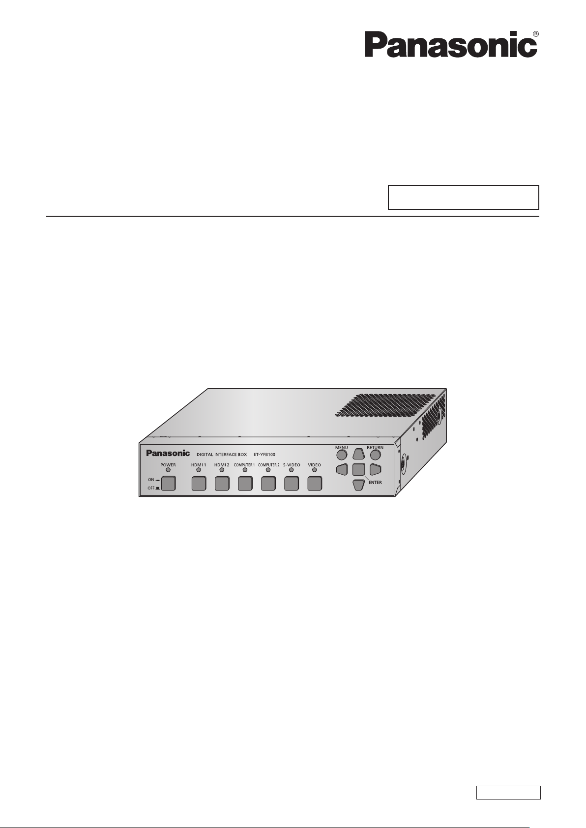
Digital Interface Box
Model No.
ET-YFB100G
Commercial Use
Thank you for purchasing this Panasonic product.
■This manual is intended for products manufactured from May 2013 and beyond.
■Before operating this product, please read the instructions carefully and save this manual
for future use.
■Before using this product, be sure to read “Read this rst!” (
pages 3 to 8).
ENGLISH
TQBH0279-2

Trademarks
• PJLinkTM is a trademark or pending trademark in Japan, the United States, and other countries and regions.
• HDMI, the HDMI Logo, and High-Denition Multimedia Interface are trademarks or registered trademarks of
HDMI Licensing LLC in the United States and other countries.
• VGA and XGA are trademarks of International Business Machines Corporation.
• SVGA is a registered trademark of the Video Electronics Standards Association.
• The font used in the on-screen displays is a Ricoh bitmap font, which is manufactured and sold by Ricoh
Company, Ltd.
• Other names, company names or product names used in these operating instructions are the trademarks or
registered trademarks of their respective holders.
Please note that the operating instructions do not include the ® and TM symbols.
Illustrations in these operating instructions
• Note that illustrations of the digital interface box and screens may differ from the ones you actually see.
Page references
• In these instructions, references to pages are indicated as: ( page 00).
Term
• In these instructions, the “Wireless remote control unit” supplied with the projector is referred to as the “Remote
control”.
• In these instructions, the “EIA standard rack” is referred to as the “Rack”.
2 - ENGLISH
Information
Read this rst!
WARNING: THIS APPARATUS MUST BE EARTHED.
WARNING: TO REDUCE THE RISK OF FIRE OR ELECTRIC SHOCK, DONOT EXPOSE THIS
PRODUCT TO RAIN OR MOISTURE.
WARNING:
1. Remove the plug from the mains socket when this unit is not in use for a prolonged period of time.
2. To prevent electric shock, do not remove cover. No user serviceable parts inside. Refer servicing to qualied
service personnel.
3. Do not remove the earthing pin on the mains plug. This apparatus is equipped with a three prong
earthingtype mains plug. This plug will only t an earthing-type mains socket. This is a safety feature. If you
are unable to insert the plug into the mains socket, contact an electrician. Do not defeat the purpose of the
earthing plug.
Power Supply: This equipment is designed to operate on 100 V - 240 V, 50 Hz/60 Hz AC, house current only.
CAUTION: The AC power cord (for USA) which is supplied with the equipment as an accessory can only
be used for power supplies up to 125 V. If you need to use higher voltages than this, you will
need to obtain a separate 250 V power cord. If you use the accessory cord in such situations,
re may result.
Read this rst!
CAUTION: To assure continued compliance, follow the attached installation instructions, which include
using the provided power cord and shielded interface cables when connecting to computer
or peripheral device. If you use serial port to connect PC for external control of projector, you
must use a commercial RS-232C serial interface cable with ferrite core. Any unauthorized
changes or modications to this equipment will void the user’s authority to operate.
CAUTION (USA and Canada)
CAUTION: This equipment is equipped with a three-pin grounding-type power
plug. Do not remove the grounding pin on the power plug. This plug
will only t a grounding-type power outlet. This is a safety feature. If
you are unable to insert the plug into the outlet, contact an electrician.
Do not defeat the purpose of the grounding plug.
Do not remove
WARNING (USA and Canada)
zNot for use in a computer room as dened in the Standard for the Protection of Electronic Computer/Data
Processing Equipment, ANSI/NFPA 75.
zFor permanently connected equipment, a readily accessible disconnect device shall be incorporated in the
building installation wiring.
zFor pluggable equipment, the socket-outlet shall be installed near the equipment and shall be easily
accessible.
ENGLISH - 3

Read this rst!
FCC NOTICE (USA)
Declaration of Conformity
Model Number: ET-YFB100G
Trade Name: Panasonic
Responsible Party: Panasonic Corporation of North America
Address: One Panasonic Way, Secaucus, NJ 07094
Telephone number: (877)803-8492
E-mail: projectorsupport@us.panasonic.com
This device complies with Part 15 of the FCC Rules.
Operation is subject to the following two conditions:
(1) This device may not cause harmful interference, and (2) this device must accept any interference received,
including interference that may cause undesired operation.
To assure continued compliance, follow the attached installation instructions and do not make any unauthorized
modications.
Caution:
This equipment has been tested and found to comply with the limits for a Class B digital device, pursuant
to Part 15 of the FCC Rules. These limits are designed to provide reasonable protection against harmful
interference in a residential installation. This equipment generates, uses and can radiate radio frequency
energy and, if not installed and used in accordance with the instructions, may cause harmful interference
to radio communications. However, there is no guarantee that interference will not occur in a particular
installation. If this equipment does cause harmful interference to radio or television reception, which can be
determined by turning the equipment off and on, the user is encouraged to try to correct the interference by
one or more of the following measures:
zReorient or relocate the receiving antenna.
zIncrease the separation between the equipment and receiver.
zConnect the equipment into an outlet on a circuit different from that to which the receiver is connected.
zConsult the dealer or an experienced radio/TV technician for help.
FCC Caution:
To assure continued compliance, follow the attached installation instructions and use only shielded interface
cables when connecting to computer and/or peripheral devices. Any changes or modications not expressly
approved by Panasonic Corp. of North America could void the user’s authority to operate this device.
NOTIFICATION (Canada)
This class B digital apparatus complies with Canadian ICES-003.
Product information (for Turkey only)
EEE Yönetmeliğine Uygundur.
EEE Complies with Directive of Turkey.
4 - ENGLISH
Read this rst!
IMPORTANT: THE MOULDED PLUG (U.K. only)
FOR YOUR SAFETY, PLEASE READ THE FOLLOWING TEXT CAREFULLY.
This appliance is supplied with a moulded three pin mains plug for your safety and convenience. A 13 amp fuse
is tted in this plug. Should the fuse need to be replaced, please ensure that the replacement fuse has a rating
of 13 amps and that it is approved by ASTA or BSI to BS1362.
Check for the ASTA mark
or the BSI mark on the body of the fuse.
If the plug contains a removable fuse cover, you must ensure that it is retted when the fuse is replaced. If you
lose the fuse cover, the plug must not be used until a replacement cover is obtained. A replacement fuse cover
can be purchased from an Authorised Service Center.
If the tted moulded plug is unsuitable for the mains socket in your home, then the fuse should be
removed and the plug cut off and disposed of safely. There is a danger of severe electrical shock if the
cut off plug is inserted into any 13 amp socket.
If a new plug is to be tted, please observe the wiring code as shown below.
If in any doubt, please consult a qualied electrician.
WARNING:
IMPORTANT:
THIS APPLIANCE MUST BE EARTHED.
The wires in this mains lead are coloured in accordance with the following code:
Green - and - Yellow: Earth
Blue: Neutral
Brown: Live
As the colours of the wire in the mains lead of this appliance may not correspond with the coloured markings
identifying the terminals in your plug, proceed as follows.
The wire which is coloured GREEN - AND - YELLOW must be connected to the terminal in the
plug which is marked with the letter E or by the Earth symbol
or coloured GREEN or GREEN -
AND - YELLOW.
The wire which is coloured BLUE must be connected to the terminal in the plug which is marked
with the letter N or coloured BLACK.
The wire which is coloured BROWN must be connected to the terminal in the plug which is
marked with the letter L or coloured RED.
How to replace the fuse: Open the fuse compartment with a screwdriver and replace the fuse.
BS1363/A
N
13A250V
HE-8
L
ASA
ENGLISH - 5

Read this rst!
WARNING:
POWER
The wall outlet or the circuit breaker shall be installed near the equipment and shall be easily
accessible when problems occur. If the following problems occur, cut off the power supply
immediately.
Continued use of the device in these conditions will result in re or electric shock.
zIf foreign objects or water get inside the device, cut off the power supply.
zIf the device is dropped and the AC adaptor is damaged, cut off the power supply.
zIf you notice smoke, strange smells or noise coming from the device, or notice the device is overheating,
cut off the power supply.
Please contact an Authorized Service Center for repairs, and do not attempt to repair the device yourself.
During a thunderstorm, do not touch the device, power cord, power plug, power connector or AC
adaptor.
Failure to observe this will result in electric shocks.
Do not do anything that might damage the power cord, power plug, power connector or AC adaptor.
If the power cord is used while damaged, electric shocks, short-circuits or re will result.
zDo not damage the power cord, make any modications to it, place it near any hot objects, bend it
excessively, twist it, pull it, place heavy objects on top of it or wrap it into a bundle.
Ask an Authorized Service Center to carry out any repairs to the power cord or AC adaptor that might be
necessary.
Completely insert the power plug into the wall outlet, the power connector into the AC adaptor terminal,
and the AC adaptor plug into the device terminal.
If the plug is not inserted correctly, electric shocks or overheating will result.
zDo not use plugs which are damaged or wall outlets which are coming loose from the wall.
Do not use anything other than the provided AC adaptor or power cord.
Please note that not using the provided power cord or AC adaptor may result in re or electric shocks caused
by a short circuit or overheating.
Clean the power plug regularly to prevent it from becoming covered in dust.
Failure to observe this will cause a re. If dust builds up on the power plug, the resulting humidity can damage
the insulation.
zPull the power plug out from the wall outlet and wipe it with a dry cloth regularly.
zWhen not using the device for an extended period of time, disconnect the power plug from the wall outlet.
Do not handle the power cord, power plug, power connector or AC adaptor with wet hands.
Failure to observe this will result in electric shocks.
Do not overload the wall outlet.
If the power supply is overloaded (ex., by using too many adaptors), overheating may occur and re will result.
6 - ENGLISH

Read this rst!
WARNING:
ON USE/INSTALLATION
Do not place the device on soft materials such as carpets or sponge mats.
Doing so will cause the device to overheat, which can cause burns, re or damage to the device.
Do not set up the device in humid or dusty places or in places where the device may come into contact
with oily smoke or steam, ex. a bathroom.
Using the device under such conditions will result in re or electrical shock.
Do not block the exhaust ports or cover them with cloth, paper, etc.
Doing so will cause the device to overheat, which can cause re or damage to the device.
zSet the device in a location where the top and side exhaust ports will not be blocked.
Do not handle the device for extended lengths of time.
Parts of the device and/or AC adaptor may become hot and cause low temperature burns* if handled for an
extended length of time.
* Persons who suffer from blood complications (such as vascular diseases, diabetes, poor/restricted
circulation) or with poor skin sensitivity (the elderly) are especially susceptible to low temperature burns.
Never attempt to remodel or disassemble the device.
High voltages can cause re or electric shocks.
zFor any inspection, adjustment and repair work, please contact an Authorized Service Center.
Do not allow metal objects, ammable objects, or liquids to enter inside of the device. Do not allow the
device to get wet.
Doing so may cause short circuits or overheating, and result in re, electric shock, or malfunction of the device.
zDo not place containers of liquid or metal objects near the device.
zIf liquid enters inside of the device, consult your dealer.
zParticular attention must be paid to children.
ACCESSORIES
Do not use the supplied power cord or AC adaptor with other devices.
Using the supplied power cord or AC adaptor with other devices may cause short circuits or overheating, and
result in electric shock or re.
Only use the provided AC adaptor and power cord when using this device.
Using an AC adaptor or power cord other than those provided may result in re.
Keep accessories (at-head Phillips screws, set legs, set leg screws, mounting bracket for securing
AC adaptor, mounting bracket screw for securing AC adaptor) out of the reach of small children.
Accidentally swallowing them can cause physical harm.
zIf you believe that parts have been swallowed, seek medical advice immediately.
ENGLISH - 7

Read this rst!
CAUTION:
POWER
When disconnecting the power cord, be sure to hold the power plug and power connector.
If the power cord itself is pulled, the lead will become damaged, and re, short-circuits or serious electric
shocks will result.
When not using the device for an extended period of time, disconnect the power plug from the wall
outlet.
Failure to do so may result in re or electric shock.
Disconnect the power plug from the wall outlet before carrying out any cleaning of the device.
Failure to do so may result in electric shock.
ON USE/INSTALLATION
Do not place heavy objects on top of the device.
Failure to observe this will cause the device to become unbalanced and fall, which could result in damage or
injury. The device will be damaged or deformed.
Do not put your weight on this device.
You could fall or the device could break, and injury will result.
zBe especially careful not to let young children stand or sit on the device.
Do not install this device in a place which is not strong enough to take its full weight or on top of a
surface which is sloped or unstable.
Failure to observe this will cause the device to fall down or tip over the device, and severe injury or damage
could result.
If installing the device to the underside of a table, be careful to choose a location where it will not be
susceptible to impact from legs, etc.
Mount screws being loosened may cause the device to fall down, which will lead to damage to or deformation
of the device.
zSecurely tighten the screws.
Do not place the device in extremely hot locations.
Doing so will cause the outer casing or internal components to deteriorate, or result in re.
zTake particular care in locations exposed to direct sunlight or near stoves.
Always disconnect all cables before moving the device.
Moving the device with cables still attached can damage the cables, which will cause re or electric shocks to
occur.
ACCESSORIES
Do not subject the AC adaptor to strong impact.
The adaptor being dropped, or suffering any other strong impact may cause a short circuit, re or electric
shock.
zAsk an Authorized Service Center to carry out repairs to the AC adaptor.
8 - ENGLISH
Quick StepsQuick Steps
Features of this productFeatures of this product
Easy setup and improved
For details, refer to the corresponding pages.
serviceability
Outputs the image, sound, ethernet, and
▶
serial control signals digitally by using
one cable with CAT5e or higher grade to
the projector
(328'11").
*1: Supported only when the interface box is connected to a
DIGITAL LINK compatible projector.
The light-weight and compact-size body
▶
is achieved that can be easily attached to
the rack or the underside of the tabletop of
the meeting desk.
*1
at a distance up to 100 m
User-friendly interface
Both the projector and the interface box
▶
can be operated by using the remote
control of the projector
interface box is installed at a separate
place from the viewing location, switching
the input signal and adjusting the image
are possible.
*1: Supported only when the interface box is connected to a
DIGITAL LINK compatible projector.
*1
. Even the
1. Set up the interface box.
( page 15)
2.
Connect the interface box
and the projector.
page 18)
(
3. Connect with other
devices.
( page 18)
4. Connect the AC adaptor.
( page 23)
Improvement of the
connectivity
Analog inputs as well as the HDMI terminal
▶
are converted and output digitally. Therefore,
transfer is possible without dropping the
picture quality.
5. Switch on the interface
box.
( page 24)
6. Select the input signal.
( page 25)
ENGLISH - 9

Contents
Be sure to read “Read this rst!”. (
pages
3 to 8)
Important Information
Read this rst! ............................................ 3
Precautions for use ................................... 11
Cautions when transporting ............................. 11
Cautions when installing .................................. 11
Disposal .......................................................... 11
Accessories ....................................................12
Preparation
About your interface box ..........................13
Main body .......................................................13
Getting Started
Setting up ...................................................15
Cautions when setting up the interface box .....15
Mounting on the rack .......................................15
Mounting to the underside of the tabletop of
the desk....................................................16
Mounting on the desk or the shelf .................... 17
Connections ..............................................18
Before connecting ...........................................18
Connecting example: Video and audio devices 19
Connecting example: Computers .....................20
Connecting to the DIGITAL LINK compatible
device ....................................................... 21
Basic Operation
[CLAMP POSITION] ........................................30
[DIGITAL CINEMA REALITY]...........................31
[POSITION] menu ..................................... 32
[SHIFT] ...........................................................32
[CLOCK PHASE] ............................................. 32
[OVER SCAN] ................................................. 32
[ASPECT] .......................................................33
[INPUT RESOLUTION] ....................................34
[LANGUAGE] menu .................................. 35
Changing the display language ........................35
[OPTION] menu ......................................... 36
[OSD DESIGN] ................................................ 36
[RGB SYNC TERMINAL]
(Only the RGB signal input) ....................... 36
[CLOSED CAPTION SETTING] ....................... 36
[BACK COLOR] ..............................................36
[SXGA MODE] ................................................37
[WIDE MODE] .................................................37
[NO SIGNAL SLEEP] ......................................37
[AUDIO SETTING] ..........................................38
[AUTO SETUP] ...............................................39
[OUTPUT RESOLUTION] ................................39
[STATUS] ........................................................40
[INITIALIZE ALL] .............................................40
Appendix
Maintenance...............................................41
Troubleshooting ....................................... 42
Frequently Asked Questions ................... 43
Switching on/off the interface box .......... 23
Connecting the AC adaptor .............................23
Switching on the interface box .........................24
Switching off the interface box .........................24
Checking the image .................................. 25
Select the input signal .....................................25
Remote control operation ........................ 26
Switching the input ..........................................26
Displaying the On-screen menu (main menu) ..26
Settings
On-screen menu navigation ..................... 27
Navigating through the menu ...........................27
Main menu ......................................................28
Sub-menu .......................................................28
[INPUT SELECT] menu ............................. 29
Switching the input ..........................................29
[PICTURE] menu ....................................... 30
[SYSTEM SELECTOR] ...................................30
Technical information ............................... 44
PJLink protocol ................................................ 44
<SERIAL IN> terminal .....................................45
<REMOTE IN> terminal ................................... 47
List of compatible signals .................................48
Corresponding 3D signals list ..........................49
Specications ........................................... 50
Dimensions ............................................... 52
Index ......................................................... 54
10 - ENGLISH

Precautions for use
Precautions for use
Cautions when transporting
zWhen transporting the interface box, avoid excessive vibration and impacts. Doing so may damage the internal
parts and result in malfunctions.
Cautions when installing
■Do not set up the interface box outdoors.
The interface box is designed for indoor use only.
■Do not set up the interface box in the following locations.
Places where vibration and impacts occur such as in a car or vehicle: Doing so may cause damage to
z
internal parts or malfunction.
Near lights (studio lamps, etc.) and other locations of great temperature uctuation (“Operating
z
environment” (
Near high-voltage power lines or near motors: Doing so may interfere with the operation of the interface
z
box.
■Always install the interface box with the bottom side down.
Doing so may shorten the life of the internal parts and result in malfunctions.
z
■When installing the interface box at a place, where electric statistic occurs
page 51)): doing so may result in malfunctions.
often, take a sufcient anti-static measure before start using.
When the interface box is used at a location, where static electricity occurs often, such as on a carpet,
z
communications of the DIGITAL LINK and the wired LAN are disconnected more often.
In that case, remove static electricity and the noise source that may cause problems with an antistatic mat,
and re-connect the DIGITAL LINK and the wired LAN.
In rare cases, the LAN connection is disabled due to static electricity or noise.
z
In that case, turn off the power of the interface box and the connected devices once and then re-turn on the
power. Connect the DIGITAL LINK and the LAN.
■The interface box may not work properly due to strong radiowave from the
broadcast station or the radio.
If there is any facility or equipment, which outputs strong radiowave, near the installation location, install
z
the interface box at a location sufciently far from the source of the radiowave. Or, wrap the LAN cable
connected to the <DIGITAL LINK> terminal by using a piece of metal foil or a metal pipe, of which is
grounded at both ends.
Disposal
To dispose of the product, ask your local authorities or dealer for correct methods of disposal.
ENGLISH - 11
Precautions for use
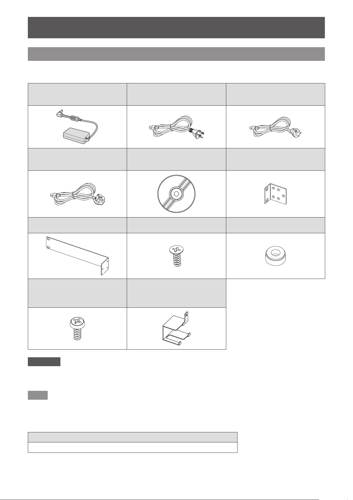
Accessories
Make sure that the following accessories are provided with your interface box. Numbers enclosed in < > show the
number of accessories.
AC adaptor <1>
(CF-AA6373AM1)
Power cord <1>
(For U.K.)
(K2CT3YY00066)
Rack mounting bracket <1>
(TKZX5278-1)
Power cord <1>
(For USA)
(K2CG3YY00152)
CD-ROM <1>
(TXFQB02VLC3)
Flat-head Phillips screw <6>
(XSS3+8FJK)
Power cord <1>
(For Europe)
(K2CM3YY00034)
Rack/table underside mounting
bracket <2>
(TKZX5277)
Set leg <4>
(TBLX3014)
Set leg screw <4>,
Mounting bracket screw for
securing AC adaptor <1>
(XSB3+6FJK)
Attention
zAfter unpacking the interface box, discard the power cord cap and packaging material properly.
zFor missing accessories, consult your dealer.
zStore small parts in an appropriate manner, and keep them away from small children.
Note
zThe model numbers of accessories and optional accessories are subject to change without notice.
Mounting bracket for securing AC
adaptor <1>
(TENC5824)
■Contents of the supplied CD-ROM
The contents of the supplied CD-ROM are as follows.
Instruction (PDF)
Operating Instructions - Functional Manual
z
12 - ENGLISH
About your interface box
About your interface box
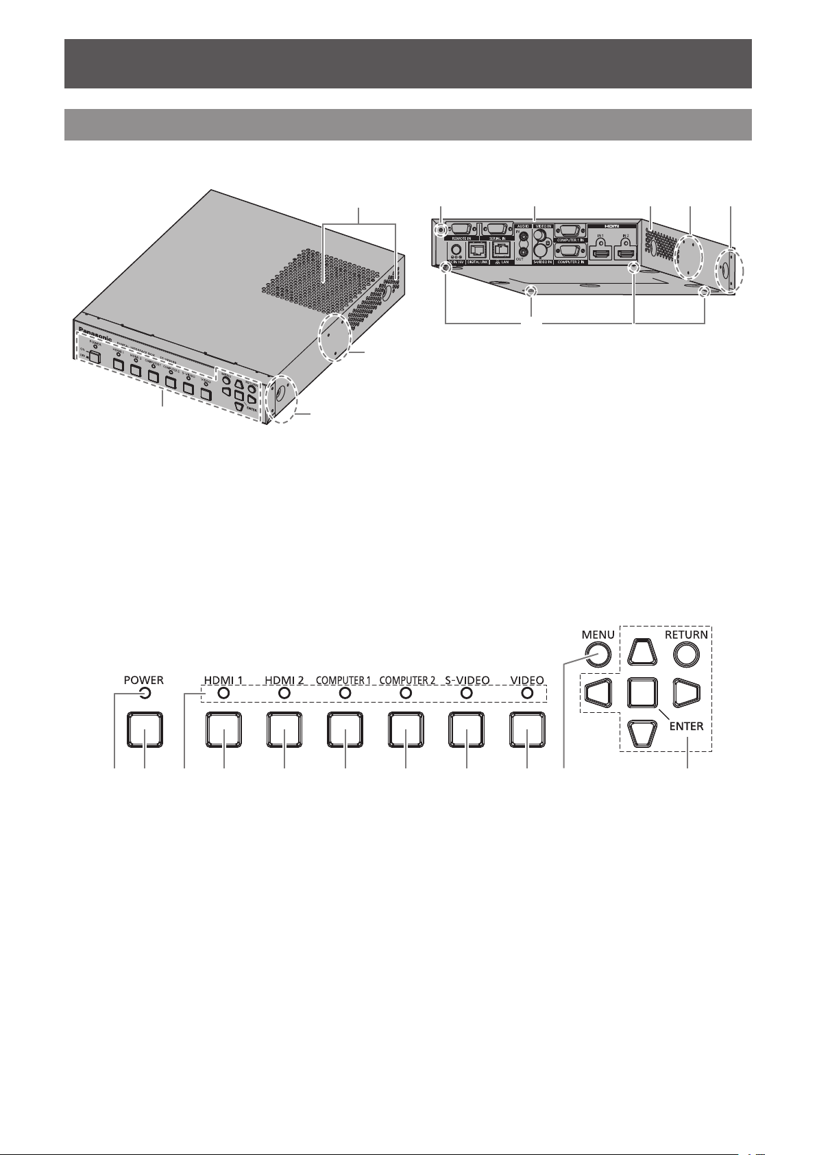
Main body
Front and lateral sides ■Rear and bottom sides
■
(4)
(7)
(3)
(3)(6) (4)(5)
(2)
(1)
(1) Control panel ( page 13)
(2) Rack mount screw hole
Screw holes for the xing bracket that is used to mount the
interface box to the rack.
(3) Table underside mount screw hole
Screw holes for the xing bracket that is used to mount the
interface box to the underside of the table.
(4) Exhaust port
Control panel
■
(4)(2) (3)(1) (5) (6) (7) (8) (9) (10) (11)
(1) Power indicator
Turns to green when the power is on. Lights off when the
power is turned off.
(2) <POWER> button
Turns on/off the power.
(3) Input terminal indicator
Turns to green when it is selected.
(4) <HDMI 1> button
Switches the input to HDMI 1.
(5) <HDMI 2> button
Switches the input to HDMI 2.
(2)
(5) Mounting bracket screw hole for securing AC
adaptor
(6) Connecting terminals (
(7) Set leg screw hole
Screw holes for xing the set legs that are used for
mounting the interface box on the desk.
(6) <COMPUTER 1> button
Switches the input to the computer 1.
(7) <COMPUTER 2> button
Switches the input to the computer 2.
(8) <S-VIDEO> button
Switches to S-VIDEO input.
(9) <VIDEO> button
Switches to VIDEO input.
(10) <MENU> button
Displays the main menu.
(11)
button
Used to operate the menu screen.
( page 23)
page 14)
selection button/<RETURN> button/<ENTER>
ENGLISH - 13

About your interface box
Connecting terminals
■
(1) (2) (4)(3)
(7) (11)(8) (9) (10)(6)
(1) <REMOTE IN> terminal
Terminal to remotely operate the interface box via the
external control circuit.
(2) <SERIAL IN> terminal
The RS-232C compatible terminal used for the external
control.
The projector connected by the DIGITAL LINK can be
externally controlled. Controlling the interface box is
disabled.
(3) <VIDEO IN> terminal
This is a terminal to input video signals.
(4) <S-VIDEO IN> terminal
This is a terminal to input S-video signals.
(5) <HDMI IN 1>/ <HDMI IN 2> terminal
This is a terminal to input HDMI signals.
(6) <DC IN> terminal
Connects the supplied AC adaptor.
(5)
(7) <DIGITAL LINK> terminal
Connects to the DIGITAL LINK
the preferred twisted-pair-cable receiver by using the cable
of CAT5e or the higher grade (
*1: DIGITAL LINK is the technique that transfers the
image, sound, ethernet, and serial control signals
via the twisted-pair-cable. The interface box can be
connected to the projector compatible to DIGITAL
LINK or the twisted-pair-cable receiver. For twistedpair-cable receivers of other manufacturers of which
the operation has been veried with the DIGITAL LINK
compatible projector and the digital interface box,
refer to Panasonic website (http://panasonic.net/avc/
projector/).
Note that the verication for devices of other
manufacturers has been made for the items
set by Panasonic Corporation, and not all the
operations have been veried. For operation or
performance problems caused by the devices of other
manufacturers, contact the respective manufacturers.
(8) <LAN> terminal
Terminal to connect to the network.
The projector connected by the DIGITAL LINK can be
controlled from the computer connected to this terminal.
(9) <AUDIO IN> terminal
Terminal to input the sound signals.
(10) <AUDIO OUT> terminal
Terminal to output the sound signal that is input to the
interface box.
(11) <COMPUTER 1 IN>/ <COMPUTER 2 IN> terminal
Terminal to input the RGB signal from the computer or the
/YPBPR signals.
YC
BCR
*1
compatible projector or
page 21).
Attention
zWire the LAN cable, which is directly connected to the interface box, only indoors.
14 - ENGLISH
Setting up
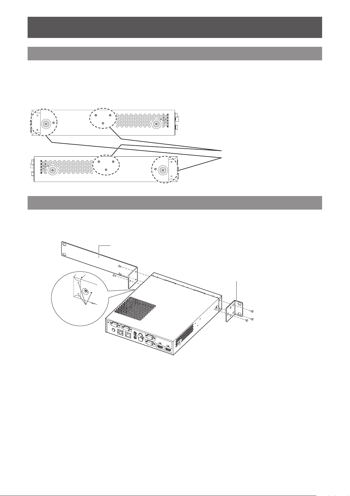
Setting up
Cautions when setting up the interface box
When mounting the interface box to a rack or a table underside, use the supplied rack/table underside
z
mounting bracket or the rack mounting bracket.
Use a torque screwdriver or torque wrench to tighten bolts to their specied tightening torques. Do not
z
use tools such as electric screwdrivers or impact screwdrivers. Tightening screws with over their specied
tightening torques will damage mount screw holes, failing to mount the interface box using brackets.
Right side
Supplied screws: Flat-head Phillips screw (M3)
Torque: 0.8 ± 0.2 N·m
Left side
Table underside mount screw hole
Rack mount screw hole
Mounting on the rack
1) Attach the supplied rack mounting bracket.
Fix the rack mounting bracket to the rack mount screw holes on both sides of the interface box with
z
supplied at-head Phillips screws (3 pcs). Securely tighten the screws.
Rack mounting bracket
Rack/table underside mounting bracket
Rack mount
screw hole
2) Attach the supplied rack/table underside mounting bracket.
Fix the rack mounting bracket to the rack mount screw holes on the both sides of the interface box with
z
supplied at-head Phillips screws (3 pcs).
ENGLISH - 15
Setting up
3) Fix to the rack by using the commercially available screws*1 (4 pcs).
*1: Use M5 or M6 screws for EIA standard rack.
Securely tighten the screws.
z
Attention
zDuring attachment, be careful that the interface box does not slip.
zBe sure to x the cables connected to the connecting terminals and the supplied AC adaptor nearby such as
the supports of the rack to avoid the cable and AC adaptor weights directly applied to the interface box.
zBe sure that the temperature inside of the rack, of which the interface box is mounted, does not exceed 40°C
(104°F).
zWhen mounting the interface box on the rack, leave 1 U (44.45 mm, 1.75") space at the upper side of the
interface box and be careful not to cover exhaust ports.
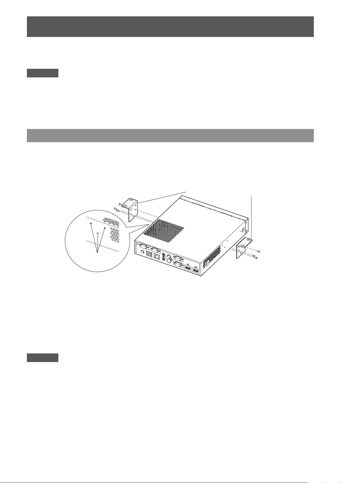
Mounting to the underside of the tabletop of the desk
1) Mount the supplied rack/table underside mounting bracket to the interface box (on
the left and right).
Mount the bracket to the table underside mount screw holes at the lateral side of the interface box with the
z
supplied at-head Phillips screws (3 pcs, each).
Be sure to tighten at the specied torque.
z
Rack/table underside mounting bracket
Table underside mount
screw hole
2) Attach the AC adaptor and a mounting bracket for securing AC adaptor.
For the attachment procedures, refer to “Connecting the AC adaptor” (
z
If the mounting bracket for securing AC adaptor is attached after the interface box is attached to the table
z
underside, excessive force may be applied to the mounting section on the table underside, which may
cause damage of the table or deformation of the interface box.
page 23).
3) Fix to the underside of the tabletop by using the commercially available screws or
wood screws (4 pcs).
Check that the tabletop is strong enough to bear the weight of the interface box.
z
Securely tighten the screws and the wood screws.
z
Attention
zWhen mounting the interface box to the underside of the tabletop of the desk, request the mounting operation
to the specialized engineer or to your dealer.
zIf the connecting terminals on the rear side become invisible when the interface box is attached to the table
underside, it is recommended to connect cables in advance before the interface box is attached to the table
underside.
zDuring attachment, be careful that the interface box does not slip. Failure to observe this may cause a aw on
the table.
zWhen mounting to the underside of the tabletop of the desk, do not mount at a position, where an operator’s
leg may collide. Mount screws being loosened may cause the device to fall down, which will lead to damage to
or deformation of the device.
zBe sure to x the cables connected to the connecting terminals and supplied AC adaptors nearby such as the
legs of the desk to avoid the cable and AC adaptor weights directly applied to the interface box.
zFor heat release, leave 3 cm (1.2") or wider space at both sides of the interface box.
zWhen using the interface box, do not place objects on the interface box. Be careful not to cover exhaust ports.
16 - ENGLISH
Setting up
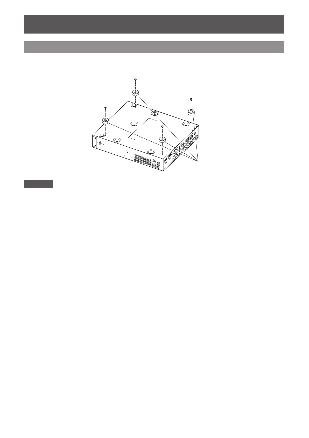
Mounting on the desk or the shelf
Mount the supplied set legs to the interface box.
Mount the legs to the set leg screw holes at the bottom side of the interface box with the supplied set leg
z
screws (4 pcs). Securely tighten the screws.
6HWOHJV
Attention
zWhen mounting the interface box on a table or on a shelf, always use the set legs. When buttons on the control
panel are pressed, the interface box may slip and cause a aw on the table or the shelf.
zWhen inverting the interface box, pay close attention not to drop or tumble.
zMount the interface box without applying excessive force, so the buttons, indicators, and connecting terminals
do not get damaged.
zPay attention to tips of the screws at the bottom side of the interface box, for not to get hurt.
zBe careful that the weights of the cables and the AC adaptors connected to the connecting terminals are not
applied on the interface box.
zWhen using the interface box, do not place objects on the interface box. Be careful not to cover exhaust ports.
For heat release, leave 3 cm (1.2") or wider space at both sides of the interface box.
ENGLISH - 17
 Loading...