

Page 1
Subject
Low Resistance Value Chip Resistor
Part No.
ERJM1W
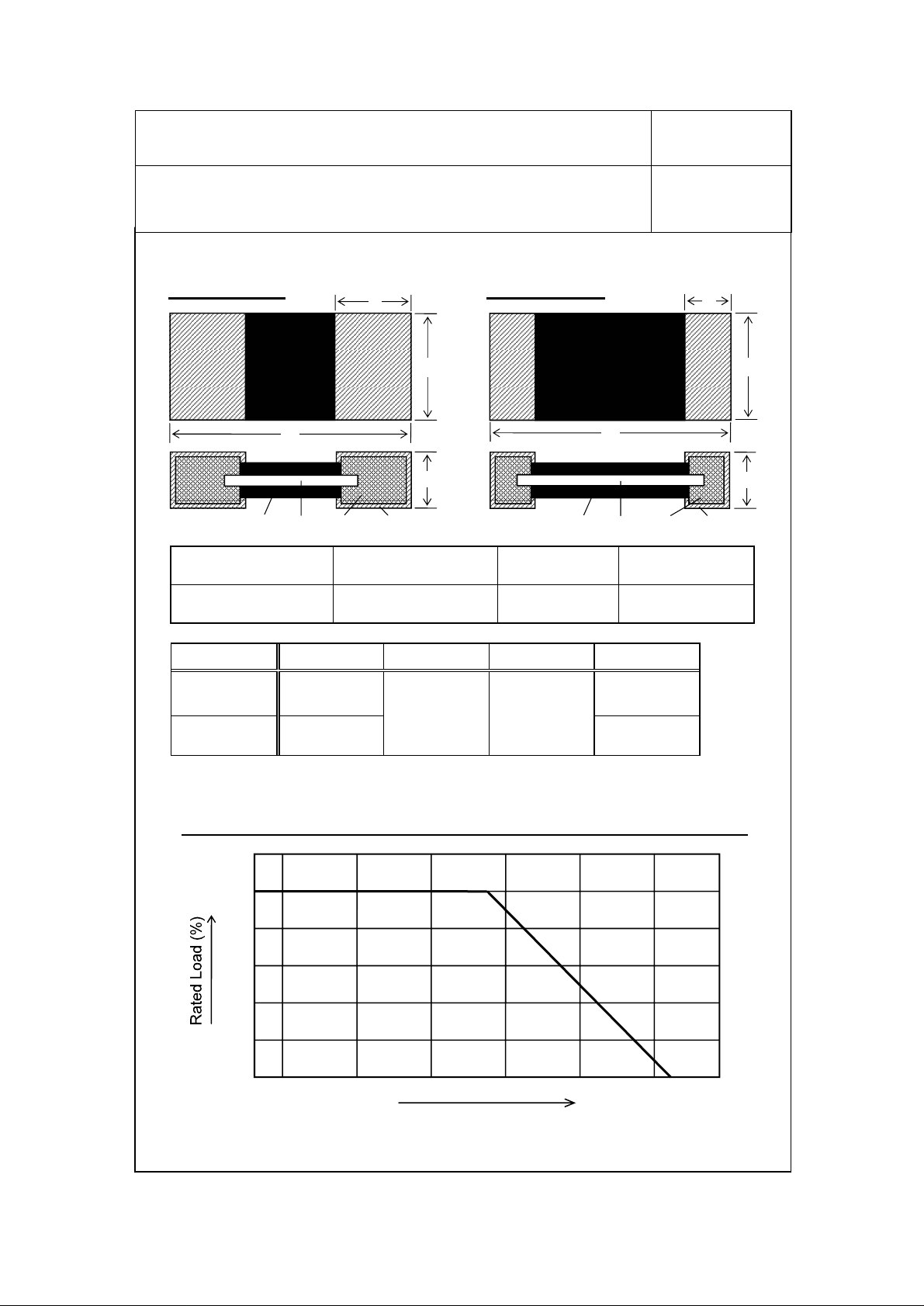
1.Dimension
ERJM1WT type
L
1)
1) Protective Coating 2) Resistive Element 3) Terminal
Resin Alloy Metal Metal
3)
a
W
T
4)2)
ERJM1WS type
1)
L
3)
4) Outer
Terminal
Metal Plating
Spec. No.
151-RJM-E01MM
1
10 -
a
W
T
4)2)
(Sn)
L W T a
ERJM1WT
ERJM1WS
2.Power Derating Curve
Category Temperature Range (Operating Temperature Range): -55 to +170 deg.C
120
100
80
60
40
20
0
6.40+/-0.40
[.252+/-.016]
6.40+/-0.25
[.252+/-.010]
-40 1200 8040 160
-55
3.20+/-0.25
[.126+/-.010]
0.80+/-0.30
[.031+/-.012]
70
2.10+/-0.30
[.083+/-.012]
1.00+/-0.25
[.039+/-.010]
Unit: mm, [inches]
170
200
Ambient Temperature (deg.C)
Fig.1
PANASONIC ELECTRONIC DEVICES CO.,LTD.
Page 2
Subject
Low Resistance Value Chip Resistor
Part No.
ERJM1W
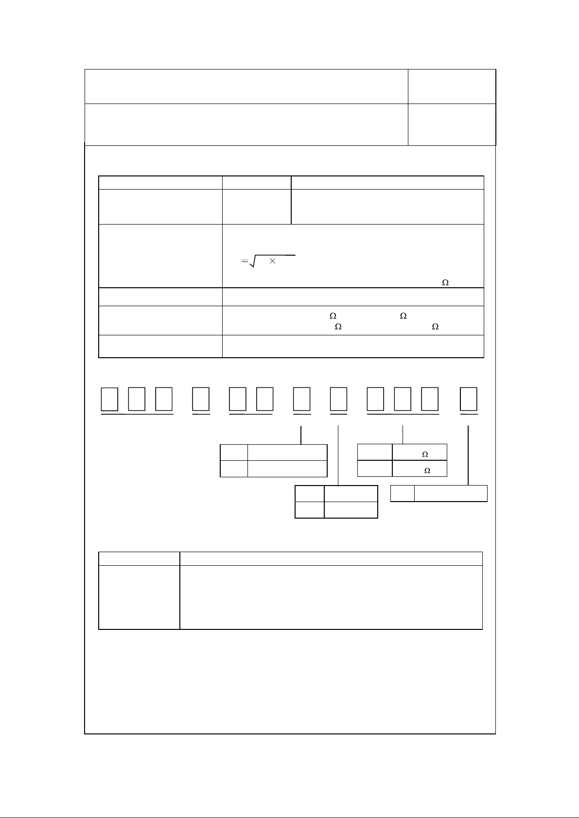
3.Ratings
Item Specifications Explanation
Power Rating
Rated Continuous Working
Voltage (RCWV)
Resistance Tolerance F:+/-1%, J:+/-5%
Resistance Range
(Standard Resistance Value)
Circuit board of use
1.0W
(70deg.C)
The rated voltage at each resistance shall be calculated from the
equation below,
E
P
E: RCWV(V), P: Rated Power(W), R: Resistance Value( )
ERJM1WT type
ERJM1WS type
You shall use the aluminum substrate when the added wattage
exceeds 0.5W.
Spec. No.
151-RJM-E01MM
10 -
When you use one at ambient temperature over
70deg.C, the load power shall be reduced as
shown in Fig.1.
R
: 1m to 4m
: 3m to 20m (3, 4, 5, 6, 10, 15, 20m )
(1, 1.5, 2, 3, 4m
)
2
4. Explanation of Part Number
E
Chip Resistor Structure Rated Power Type Tolerance Resistance Value Packaging
(Ex.)
T Wide Terminal
S Standard Terminal
5. Appearance and Construction
Item Specifications and Explanation
1. The surface of resistor is covered with protective coating and hard to
fade, then don't have unevenness, flaw pinhole and discoloration.
Appearance and
Construction
2. The surface of terminal is covered by the plating. And the plating is
hard to fade, then don't have unevenness, flaw, pinhole and
discoloration.
3. The terminal is connected with resistive plate certainly.
F +/- 1%
J +/- 5%
3M0 3m
10M 10m
U Embossed Taping
UM 03FSW1MJR
PANASONIC ELECTRONIC DEVICES CO.,LTD.
Page 3
Subject
Low Resistance Value Chip Resistor
Part No.
ERJM1W
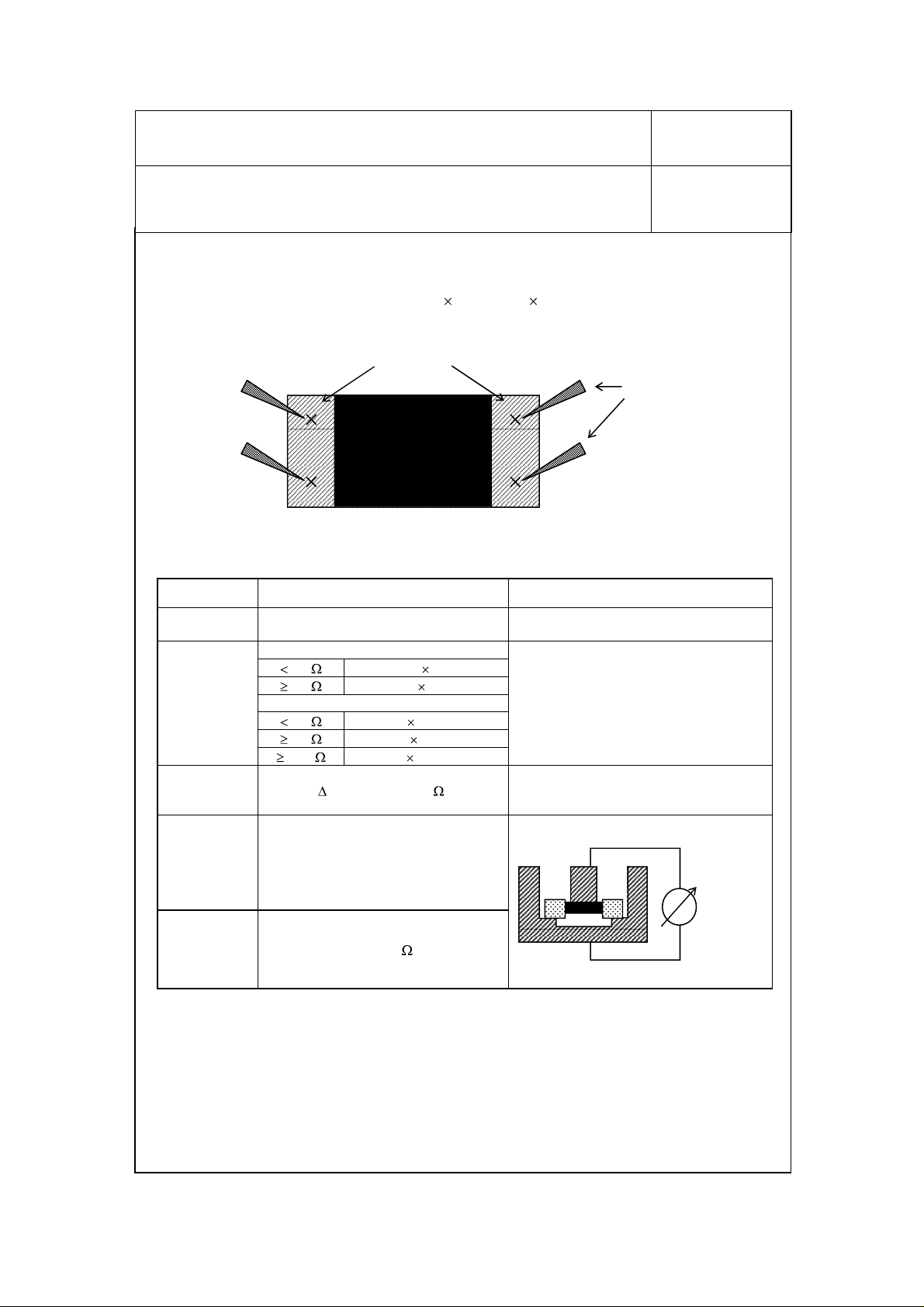
As far as there shall not designation especially, the following test and measurement
shall be operated under normal temperature(5 to 35deg.C), normal humidity(45 to
85%), normal atmospheric pressure(8.6
Resistance value shall be
<Measuring method: In measuring resistance value, 4 wires must be put on top terminal.>
6.Electrical Performance Characteristics
guaranteed as like followings.
Top terminal
104 to 1.06
105Pa).
Spec. No.
151-RJM-E01MM
Wire
10 -
3
Item Specifications Test
DC
Resistance
Temperature
Coefficient
Intermittent
Overload
Dielectric
Withstanding
Insulation
Resistance
DC Resistance value must be within
the specified tolerance.
ERJM1WT type
2m
2m
5m
5m
10m
No evidence of flash over, mechanical
damage, arcing or insulation
breakdown.
350+/-100
100+/-50
ERJM1WS type
+/-350
R = +/-(5%+0.5m
min.1G
+/-100
+/-75
10-6/deg.C
10-6/deg.C
10-6/deg.C
10-6/deg.C
10-6/deg.C
)
Methods(Based on JIS - C5201)
Measuring current: 1A
20deg.C 65%RH
Sequence of temperature:
+25deg.C to +125deg.C
Resistance change after 1,000 cycles (1
second ON, 25 seconds OFF) at 5 times
Rated Power.
AC500V 1 minute
Insulation
Resistance
Meter
or
AC Power
Supply
Measuring Voltage :DC500V
PANASONIC ELECTRONIC DEVICES CO.,LTD.
Page 4

Subject
Low Resistance Value Chip Resistor
Part No.
ERJM1W
7.Mechanical Performance Characteristics
Item Specifications Test Methods(Based on JIS-C5201)
Terminal Strength min. 4.9N
Spec. No.
151-RJM-E01MM
10 -
Copper plate: t = 0.4mm
Pull speed :10mm/seconds
Fixed
Solder
(Pb/Sn = 40/60)
Substrate : Glass Epoxy (t=1.6mm)
Span : 90mm
Bending Distance : 2mm (10 seconds)
A B C
ERJM1WT
ERJM1WS
3.1 2.2
2.1 4.2
A
3.4
Unit: mm
AB
4
P
Bending Strength
Without distinct deformation
in appearance
Solderability min. 95% coverage
Resistance to
Soldering Heat
R = +/-(5%+0.5m
C
Test Board
100mm
Resistors shall be dipped in the melted
solder bath at 230+/-5deg.C for 3+/-0.5
seconds. Next, flux shall be removed from
the surface of terminal with clean organic
solvent.
Resistors shall be dipped in the melted
solder bath at 270+/-3deg.C for 10+/-1
)
seconds.
40mm
PANASONIC ELECTRONIC DEVICES CO.,LTD.
Page 5

Subject
Low Resistance Value Chip Resistor
Part No.
ERJM1W
8.Enviromental Characteristics
Item Specifications Test Methods(Based on JIS-C5201)
High Temperature
Exposure
Temperature
Cycling
Humidity
(Steady State)
Load Life
Load Life in
Humidity
R = +/-(1%+0.5m
R = +/-(1%+0.5m
R = +/-(1%+0.5m
R = +/-(3%+0.5m
R = +/-(3%+0.5m
Spec. No.
151-RJM-E01MM
Resistors shall be exposed at 125+/-3deg.C
)
for 1000+48/-0 hours.
-55+/-3deg.C 30minutes
Normal temp. 30minutes 5 cycles
)
+125+/-3deg.C 30minutes
Resistors shall be exposed at 60+/-2deg.C
and 90 to 95% relative humidity in a humidity
)
test chamber for 1000+48/-0 hours.
Resistors shall be exposed at 70+/-2deg.C for
1000 +48/-0 hours. During this time the
)
rated voltage shall be applied intermittently for
1.5 hours ON,0.5 hours OFF.
Resistors shall be exposed at 60+/-2deg.C
and 90 to 95% relative humidity for
1000+48/-0 hours. During this time the rated
)
voltage shall be applied intermittently for 1.5
hours ON,0.5 hours OFF.
10 -
5
9.Other Characteristics
Item Specifications Test methods
Surface
Temperature
less than
110deg.C up
10.Resistance Value Marking
Express resistance value on resin side.
ERJM1WT type
ERJM1WS type
1m
:1M0 , 1.5m
3m
11.Recommended Pad Layout
ERJM1WT type
3.1mm
3.4mm
2.2mm
Resistor shall be mounted on aluminum
substrate (t = 1.0mm). A power of 1.0W
shall be applied. The temperature rise at the
center of resistor is measured.
Example
:1M5 , 2m
:R002 , 3m :R003 , 4m
:3M0 , 4m :4M0 , 5m :5M0 , 6m
10m
:10M , 15m
Circuit Pattern
(Cu etc.)
Pad
Resist
:15M, 20m
ERJM1WS type
2.1mm
4.2mm
:R004
:6M0
:20M
3.4mm
12.Manufacturing Country
Indonesia or Japan
PANASONIC ELECTRONIC DEVICES CO.,LTD.
Page 6

Subject
Low Resistance Value Chip Resistor
Part No.
ERJM1W
Spec. No.
151-RJM-E01MM
10 -
13. Precautions in Handling Resistors
! Precautions in Handling Resistors
(1) This specification shows the quality and performance of a unit component. Before adoption,
be sure to evaluate and verify the product mounting it in your product.
(2) We take no responsibility for troubles caused by the product usage that is not specified in this
specification.
(3) In traffic transportation equipment(trains, cars, traffic signal equipment, etc.), medical
equipment, aerospace equipment, electric heating appliances, combustion and gas
equipment, rotating equipment, disaster and crime preventive equipment, etc. in cases where
it is forecast that the failure of this product gives serious damage to the human life and
others, use fail-safe design and ensure safety by studying the following items to
Ensure safety as the system by setting protective circuits and protective equipment.
Ensure safety as the system by setting such redundant circuits as do not cause danger by
a single failure.
(4) When a doubt shall be occurred about safety for this product, be sure to inform us rapidly,
operate your techni
(5) The products in this specification are intended for use in general standard applications for
general electronic equipment(AV products, household electric appliances, office equipment,
information and communication equipment, etc.); hence, they do not take the use under the
following special environments into consideration. Accordingly, the use in the following
special environments, and such environmental conditions may affect the performance of the
products; prior to use, verify the performance, reliability, etc. thoroughly
1) Use in liquids such as water, oil, chemical, and organic solvent
2) Use under direct sunlight and in outdoor and dusty atmospheres
3) Use in places full of corrosive gases such as sea breeze, Cl2, H2S, NH3, SO2, AND NOX.
4) Use in environment with large static electricity and strong electromagnetic waves.
5) Where the product is close to a heating component, and where an inflammable such as
a polyvinyl chloride wire is arranged close to the product.
6) Where the resistor is sealed and coated with resin, etc.
7) Where water or a water-soluble detergent is used in cleaning free soldering and in flux
cleaning after soldering. (Pay particular attention to a water-soluble flux.)
(6) If transient load (heavy load in a short time) like pulse is expected to be applied, carry out
evaluation and confirmation test with resistors actually mounted on your own board. When
the load more than rated power is applied under the load condition at steady state, it may
impair performance and/or reliability of resistor. Never exceed the rated power.
(7) The resistor temperature is dependent on the circuit board and pattern to be used, the heat
from the neighboring components and ambient temperatures. The resistor temperature may
rise up to 170deg.C (upper limit of Category Temperature Range (Operating Temperature
Range)) or higher even if you keep the rated power. Prior to use, be sure to evaluate the
product mounted on your own board, and then use it under the condition not to damage the
board and the neighboring components. When the product shall be used under special
condition, be sure to ask us in advance.
(8) Halogen type (Chlorine type, Bromine type, etc.) or other high-activity flux is not recommended
as the residue may affect performance or reliability of resistors.
(9) When soldering with soldering iron, never touch the body of the chip resistor with a tip of the
soldering iron. When using a soldering iron with a tip at high temperature, solder for a time
as short as possible. (3 seconds or less up to 350deg.C)
(10)Avoid physical shock to the resistor and nipping of the resistor with hard tool (a pair of pliers
or tweezers) as it may damage protective film or the body of resistor and may affect resistor's
performance.
(11)Keep the rated power and ambient temperature within the specified derating curve.
(12)Avoid immersion of chip resistor in solvent for a long time. Prior to use, verify the
performance.
cal examination.
6
PANASONIC ELECTRONIC DEVICES CO.,LTD.
Page 7

Subject
Low Resistance Value Chip Resistor
Part No.
14.Storage Method
ERJM1W
Spec. No.
151-RJM-E01MM
7
10 -
If the product is stored in the fo
performance and solderability may be badly
llowing environments and conditions, the
affected, avoid the storage in the
following environments.
1) Storage in places full of corrosi
ve gases such as sea breeze, Cl2, H2S, NH3, SO
and NOX.
2) Storage in places expos
3) Storage in places outside the tem
ed to direct sunlight.
perature range of 5 to 35deg.C and humidity
range of 45 to 85%RH.
4) Storage over one year after our delivery (T
the storage method specified in
Item 1) - 3) have been followed.)
his item also applies to the case that
15. Law, Regulation
1) This product has not been manufactur
controlled under the M
ontreal Protocol.
2) This product complies with the RoHS Dire
Hazardous. Substances in elec
trical and electronic equipment
ed with any ozone depl
ctive (Restriction of
(DIRECTIVE 2002/95/EC)).
3) All the materials used in this par
Concerning the Examinat
ion and Regulation of Manuf
t are registered material under the Law
actures, etc. of
Chemical substances.
4 All the materials used in this part c
ontain no brominated materials of PBBOs
or PBBs as the flame-retardant.
5) If you need the notice by letter of "A
preliminary judgement on the Laws of Japan
foreign exchange and Foreign Trade control", be sure to let us know.
2
eting chemical
the use of certain
PANASONIC ELECTRONIC DEVICES CO.,LTD.
Page 8

Subject
Low Resistance Value Chip Resistor
Part No.
ERJM1W
16. Recommendable reflow soldering profile
Spec. No.
151-RJM-E01MM
8
10 -
Soldering by the above-menti
Notes
Soldering profile is measured at t
oned conditions is available.
he mounting position of the resistor.
Reflow soldering shall be within two times.
The regulation is for the resistor and applies to
10-4
Resistance to Soldering Heat 2
The problems caused by solder and flux are not our responsibility.
PANASONIC ELECTRONIC DEVICES CO.,LTD.
Page 9

Subject
Low Resistance Value Chip Resistor
Part No.
ERJM1W
Taping
1. Application Range
This specification covers t
2. Physical Dimensions
2-1 Structure and reel dimensions s
Carrier Tape
(Embossed)
Adhesive Tape
aping spec. of ERJM1W Type.
Top Tape
Spec. No.
151-RJM-E01MM
hall be as shown in the figure below.
15.4+/-1.0
13+/-1.0
min.60
13+/-1.0
9
10 -
180+0/-3.0
2-2 Carrier Tape Dimensions
T
T2
A B W F E P1
3.60+/-0.20
[.141+/-.008]
P2 P0
4.00+/-0.05
[.157+/-.002]
D0
D1
6.90+/-0.20
[.272+/-.008]
8.00+/-0.10
[.314+/-.004]
P1
P2 P0
Compartment
12.0+/-0.30
[.472+/-.012]
D0 D1
1.50+0.10/-0
[.059+0.04/-0]
B
A
5.50+/-0.05
[.217+/-.002]
Min. 1.50
[Min. .059]
Sprocket Hole
E
F
Chip Resistor
1.75+/-0.10
[.069+/-.004]
T T2
Max. 0.40
[Max. .016]
Unit: mm, [inches]
Unit : mm
W
8.00+/-0.10
[.314+/-.004]
1.60+/-0.10
[.063+/-.004]
PANASONIC ELECTRONIC DEVICES CO.,LTD.
Page 10

Subject
Low Resistance Value Chip Resistor
Part No.
Spec. No.
ERJM1W
3. Specifications
3-1 Specifications of Taping
When the test shall be operated with the
be 0.098N to 0.686N and the t
<Test Method>
Carrier Tape
Minimum Bending Radius
When the carrier tape shall be bent to
shall be no defection of chip and no break of
shall be done for 1 time.
Resistance to climate
When resistors shall be exposed at 60deg.
shall be no defection of chip and no break of carrier tape. When the top tape
shall be peeled, it shall
not have flash and tear.
ape shall not have flash
10
below conditions, the peel strength shall
and tear after peeling.
Peeling Direction
Top Tape
Minimum Bending Radius (15mm), there
the carrier tape. However the test
C, 90 to 95 %RH for 120 hours, there
151-RJM-E01MM
10
10 -
3-2 Quantity in Reel : 3000 pcs./reel
3-3 Taping Condition
Chip resistors shall not be st
Chip resistors shall be easy to take out from carrier tape.
Compartment and sprocket hole shall not have flash
4. Outer Packaging
When reels shall not reach Max. quantity, the remaining empty space shall be
buried with buffer material.
When the quantity shall be few, alternative packaging methods may be used. No
problem must occur during t
5. Marking
Side of Reel(Marking shall be on one side.)
1) Part Name('Fixed metal plate flat ch
2) Part Number 3) Quantity 4) Lot Number 5) Maker Name
6) Manufacturing Country
Packaging Box
1) Part Number 2) Quantity 3) Maker Name
icking to top tape and bottom tape.
and break.
Tape
Marking
he exportation of the product.
ip resistor' following part name on invoice)
PANASONIC ELECTRONIC DEVICES CO.,LTD.
 Loading...