

Panasonic EP3202-U1, EP3203 Service Manual
ORDER NO.HPD0401U11C1
E11
MASSAGE LOUNGER
EP3203/EP3202-U1
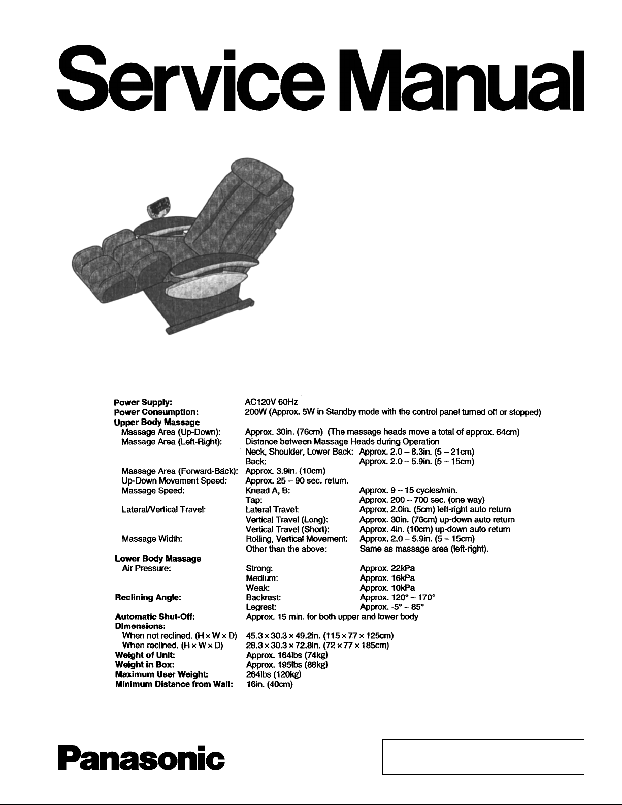
SPECIFICATIONS
© 2004 Matsushita Electric Works, Ltd. All rights
reserved. Unauthorized copying and distribution is a
violation of law.
EP3203-U1
CONTENTS
Page Page
1 COMPONENTS IDENTIFICATION 3
2 MASSAGE RANGE (MOVEMENT RANGE OF MASSAGE
WHEELS) SHIATSU MASSAGE, SWEDISH MASSAGE,
KNEADING, VIBRATING, TAPPING A, TAPPING B, TAPPING
C, WHOLE BACK ROLLING, REGIONAL ROLLING 5
3 TURNING ON THE POWER
4 REQUIRED TOOLS
5 ACTUAL WIRING DIAGRAM
6 DISPLAY METHOD OF MASSAGE BLOCK TOTAL USE TIME
AND OPERATION TIME
7 MOTION OF THE CLUTCH AND BELT BASED ON VARIOUS
MASSAGER OPERATIONS
8 CONTROL OF THE AIR-MASSAGE OPERATION
9 MASSAGER UP/DOWN SENSOR GEAR ADJUSTMENT
METHOD
6
10 DISASSEMB LY AND ASSEMBLY INSTRUCTION
11 ACTUAL WIRING DIAGRAM
7
8
12 CHECKING
13 GREASE
9
14 EXPLODED VIEW
15 REPLACEM ENT PARTS LIST
10
12
13
14
50
52
59
61
68
2
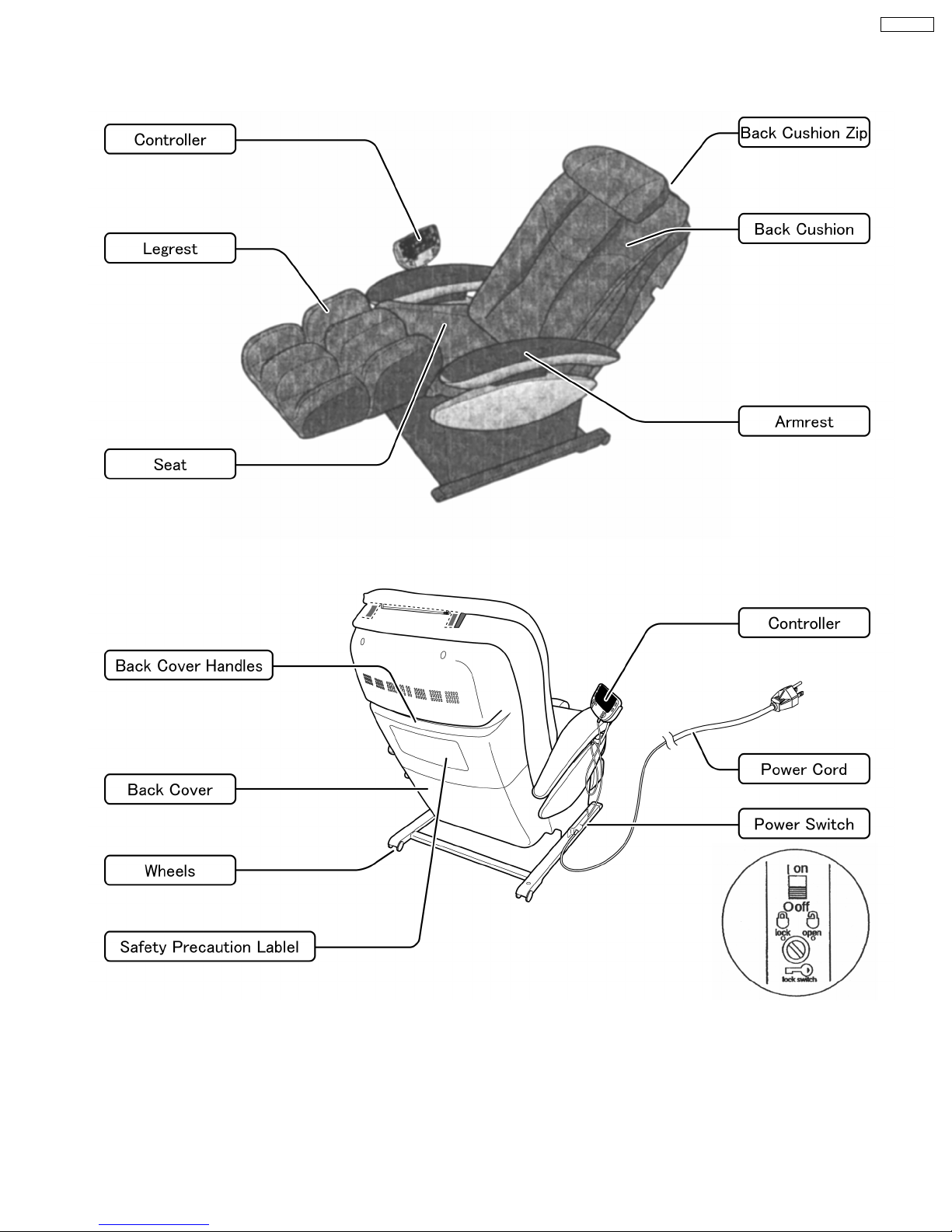
1 COMPONENTS IDENTIFICATION
1.1. Massage lounger
EP3203-U1
3
EP3203-U1
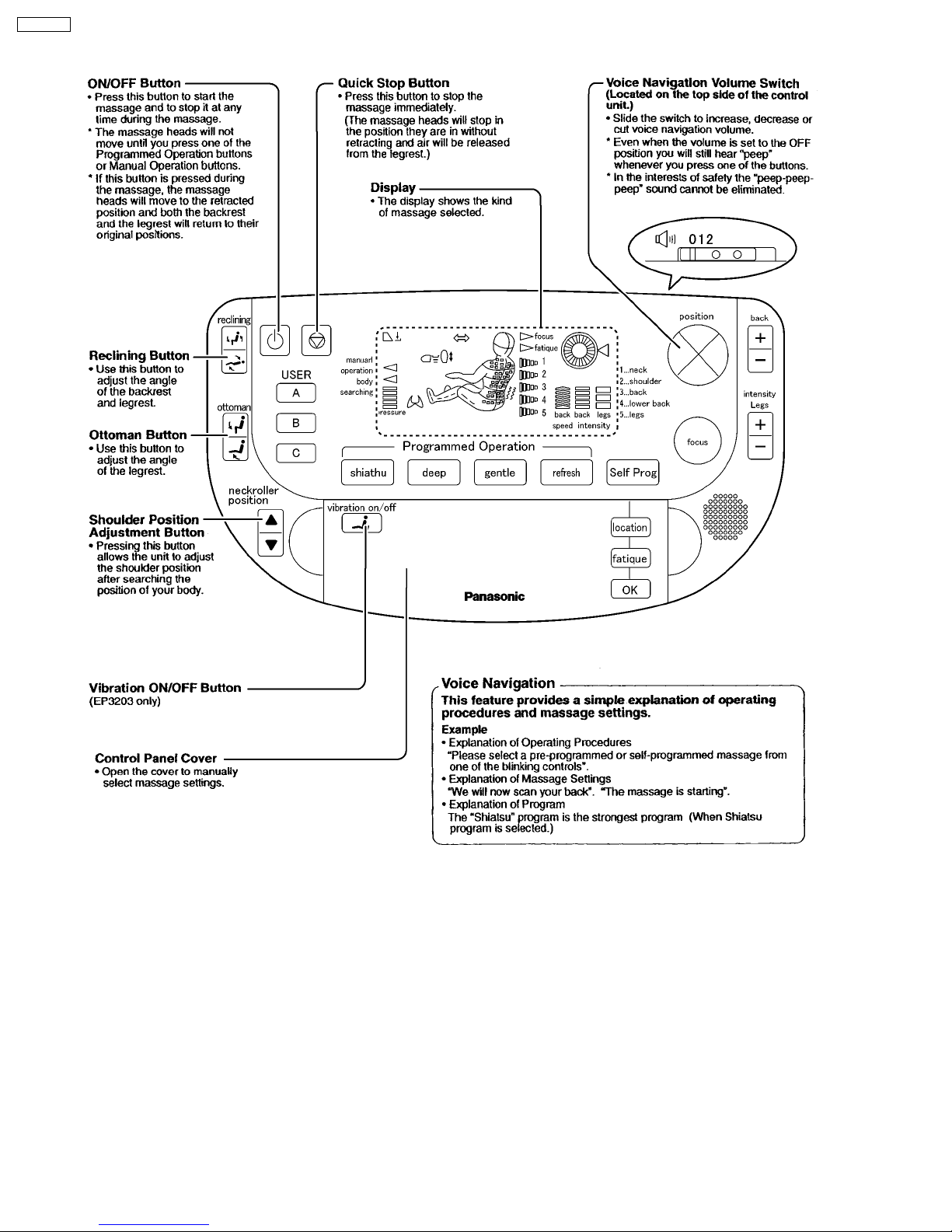
1.2. Controller
4
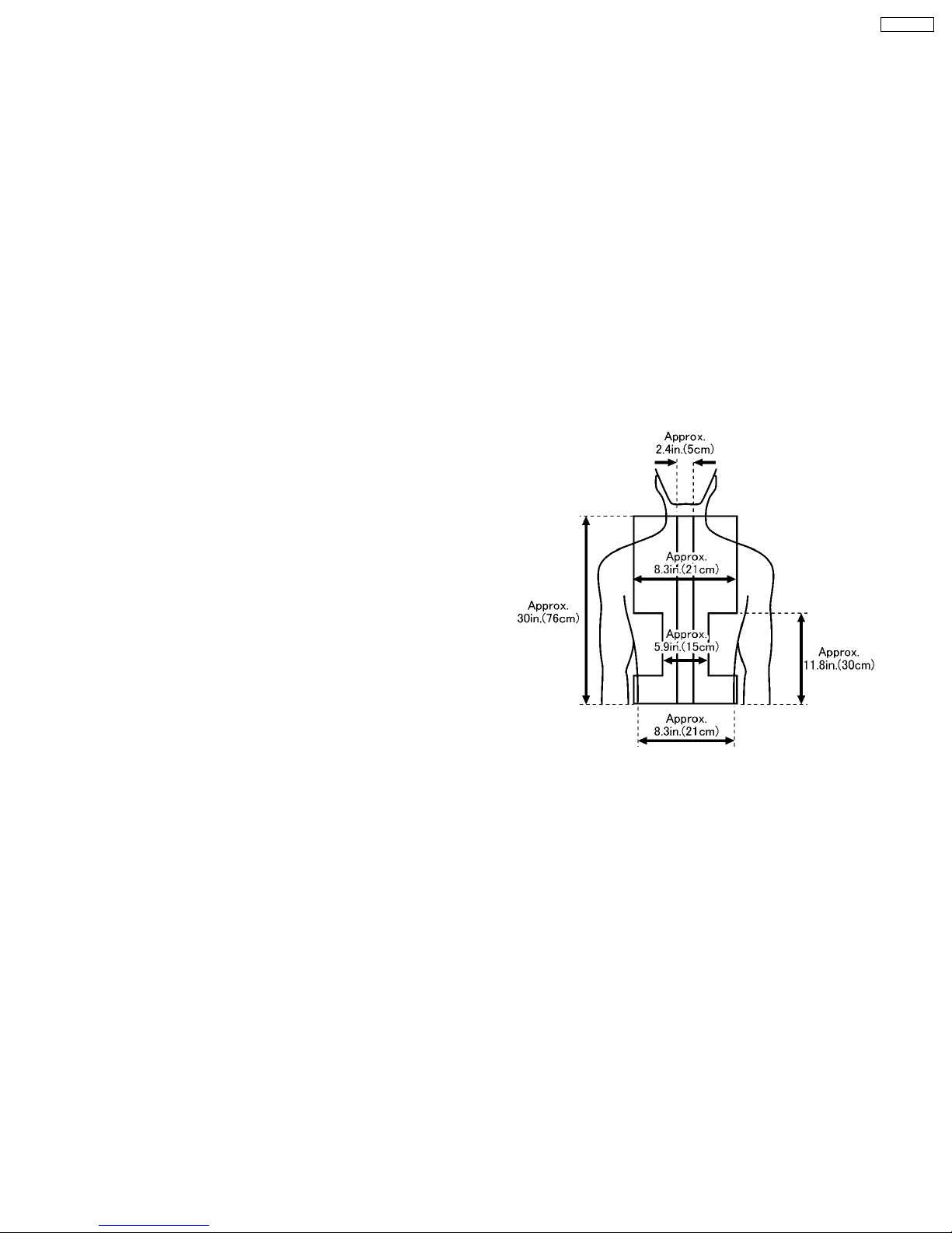
2 MASSAGE RANGE (MOVEMENT RANGE OF MASSAGE
WHEELS) SHIATSU MASSAGE, SWEDISH MASSAGE,
KNEADING, VIBRATING, TAPPING A, TAPPING B,
TAPPING C, WHOLE BACK ROLLING, REGIONAL
ROLLING
Width adjustment
Approx.50 to 210 mm (2.4in. to 8.3in.)
Intensity adjustment
Shiatsu, Swedish, Knead, vibration, Tap A, Tap B, Tap C,
whole back roll, and Regional roll (from gentle to strong)
:50mm(2.4in.)-wide adjustability where massage heads
push out toward body as intensity increases.
EP3203-U1
5
EP3203-U1
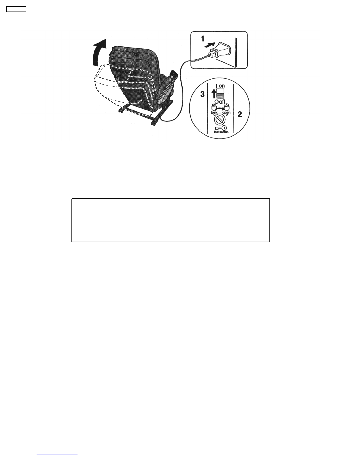
3 TURNING ON THE POWER
1. Plug the power plug into the power socket.
2. Turn the lock switch to the open position.
3. Turn on the power switch on the back of the unit.
· When the operating lock switch is pointing toward ´lock´, the power switch cannot be moved to the ´on´ position.
After each use.
·
Be sure to turn the power switch to ´off´.
·
To prevent children from using this unit, lock the power switch by moving the operating
lock switch to the ´lock´ position.
·
As a further caution, unplug the power cord from the power socket after each use.
Timer
When the on/off button is pushed, a timer begins to prevent overuse. After approximately 15 minutes, time expires and the
massage wheel goes into storage position.
6
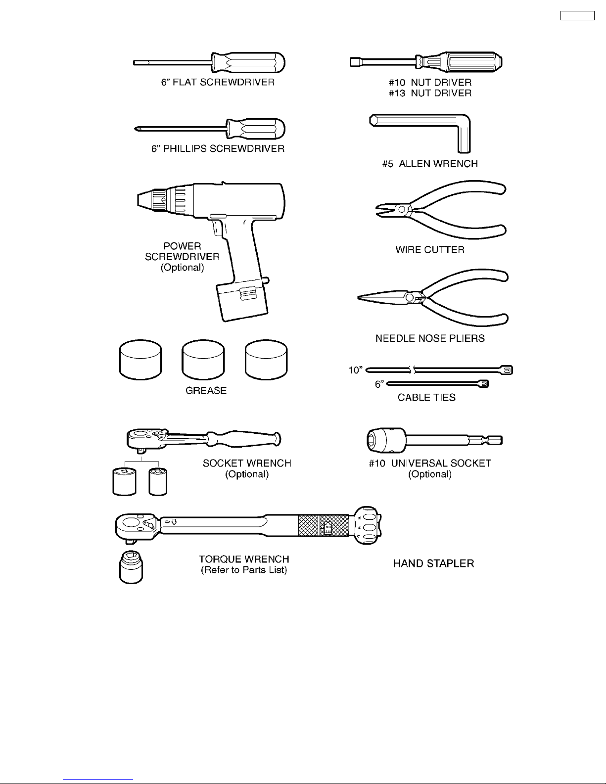
4 REQUIRED TOOLS
EP3203-U1
7
EP3203-U1
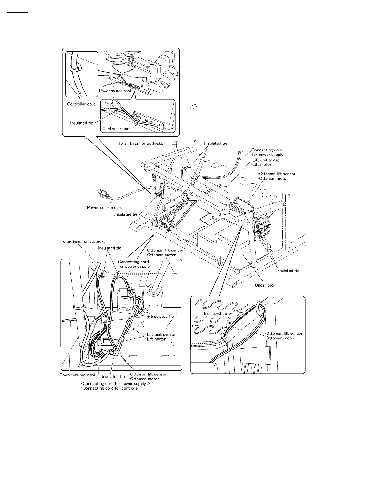
5 ACTUAL WIRING DIAGRAM
5.1. Connecting cord for power source to Sub PCB
8
6 DISPLAY METHOD OF MASSAGE BLOCK TOTAL USE
TIME AND OPERATION TIME
Adjustment of pressure sensor
First, keep the Massage mechanism block unloaded with pressure and move it upward halfway.
If the Massage mechanism block is at the highest or lowest position, you cannot arrange the pressure sensor correctly because
the fabric becomes tense with pressure.
1. While pushing On/off button and the User program button B simultaneously, turn on the power switch and continue to hold the
buttons for approximately 5 seconds. Release after the Focus button lights up.
2. Push the Focus button and automatically it lights off.
Turn off the Power source switch and turn it on again, then the adjustment is finished.
EP3203-U1
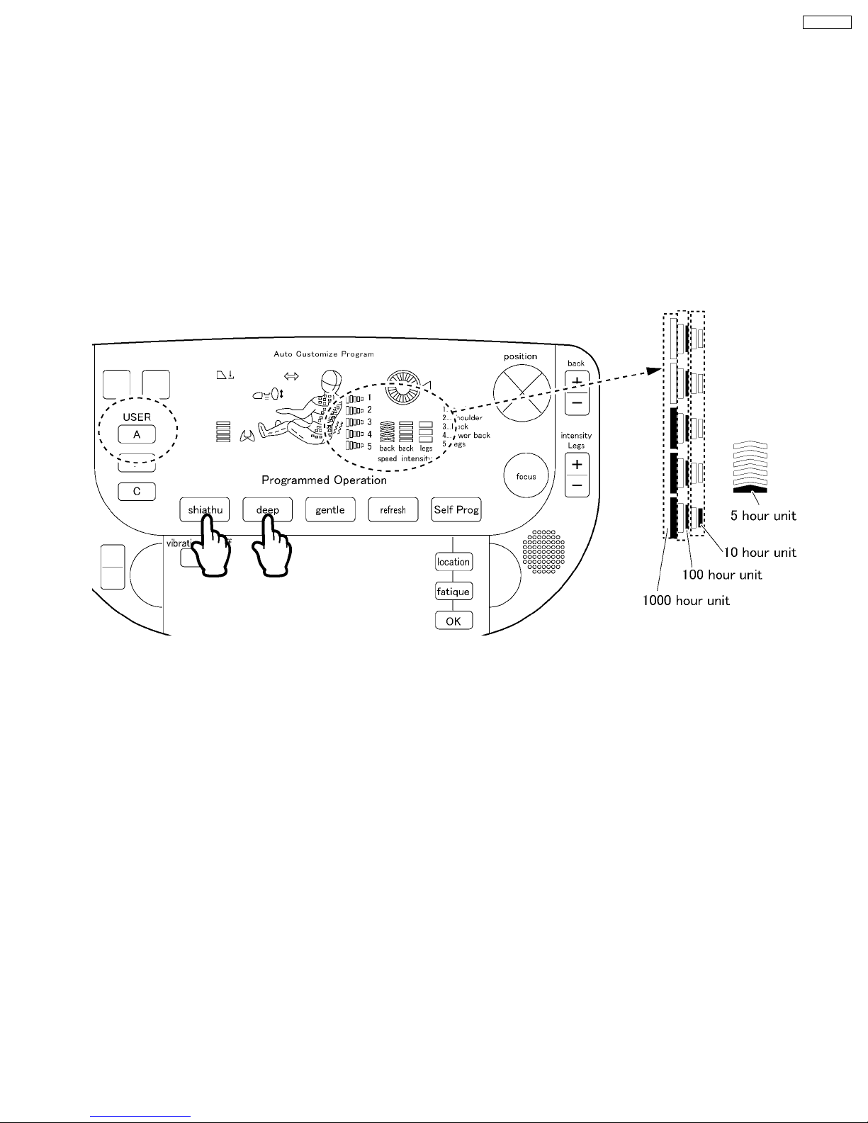
Total use time & Display method
While pushing the Shiatsu button and the Deep button simultaneously, turn on the power switch and continue to hold the
buttons for approximately 5 seconds. Release after the User program button A.
e.g. In the above case, 3000 + 500 + 10 + 5 = 3515 hours.
It is possible to indicate up to 5,995 hours.
If the use time is less than 5 hours, 5 hour unit does not light up. If it is less than 10 hours, one 5 hour unit lights up.
9
EP3203-U1
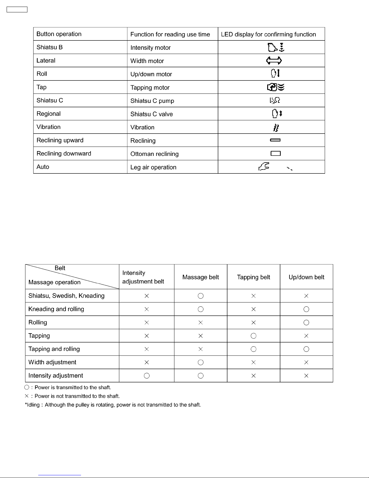
Chart for reading each function use time
7 MOTION OF THE CLUTCH AND BELT BASED ON
VARIOUS MASSAGER OPERATIONS
Massager operation and belt motion
10
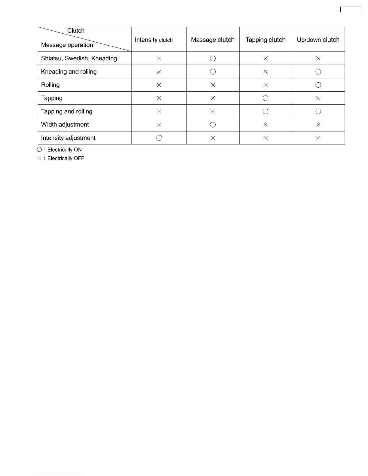
Massager operation and clutch motion
EP3203-U1
11
EP3203-U1
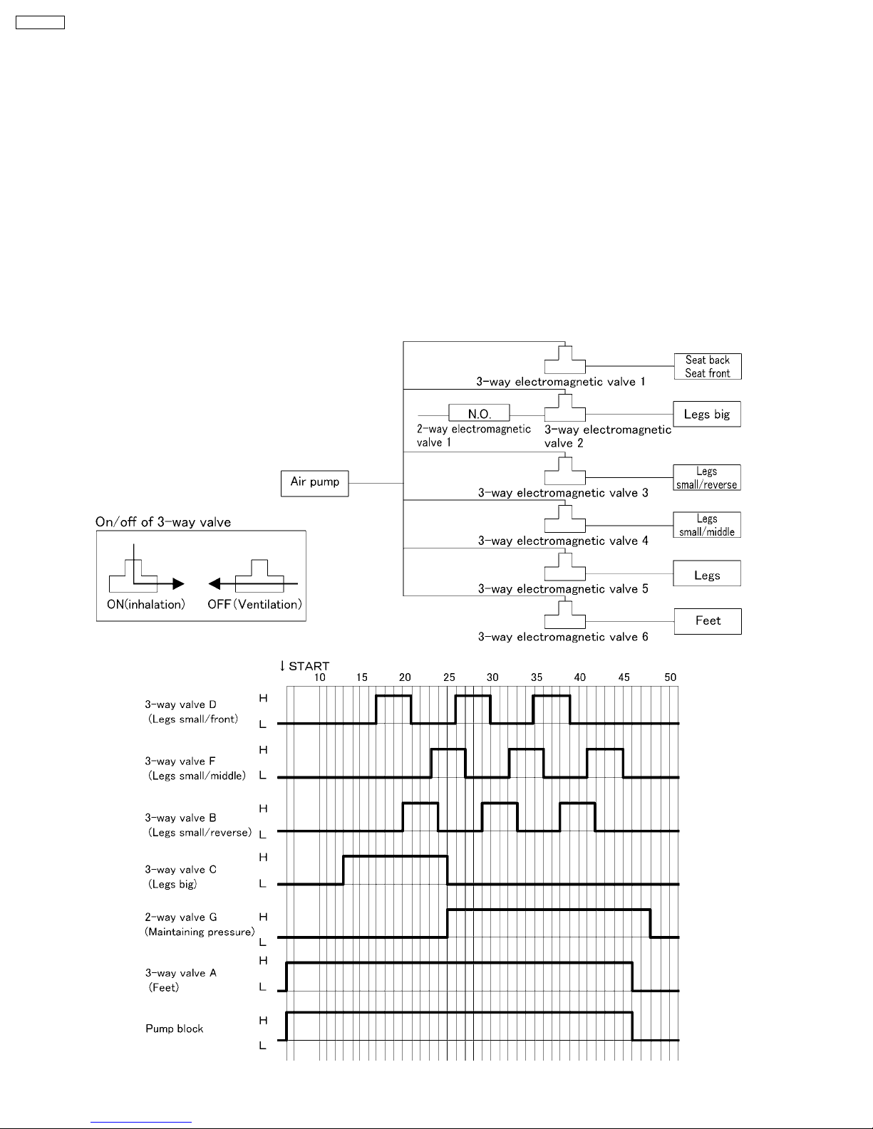
8 CONTROL OF THE AIR-MASSAGE OPERATION
Air massage functions with the operations of the pump unit x 1pc, 3-way electromagnetic valve x 1pc, and 2-way
electromagnetic valve x 2pcs.
1. Air massage is operated by the pump and electromagnetic valves.
2. When not in operation, all the pump and the electromagnetic valves are in Off position.
3. When the Reclining lift motor and the Ottoman lift motor are in operation, the control of air is stopped. (Electromagnetic is
Off. In ventilation.)
4. When you operate the electric reclining lift or the electric Ottoman lift while you operate On/off button or it is in waiting mode,
stop the operation of the pump. (The pressure of electromagnetic valves are maintained.) And after the operation
stop(retracting mode) from the retracting mode and stop mode, or after electric reclining lift or electric Ottoman lift stop in
the waiting mode, air massage stops in 5 seconds.
*After the 3-way electromagnetic valve of Legs big turns Off , turn On the 2-way electromagnetic valve and maintain the
pressure of Legs big.
12
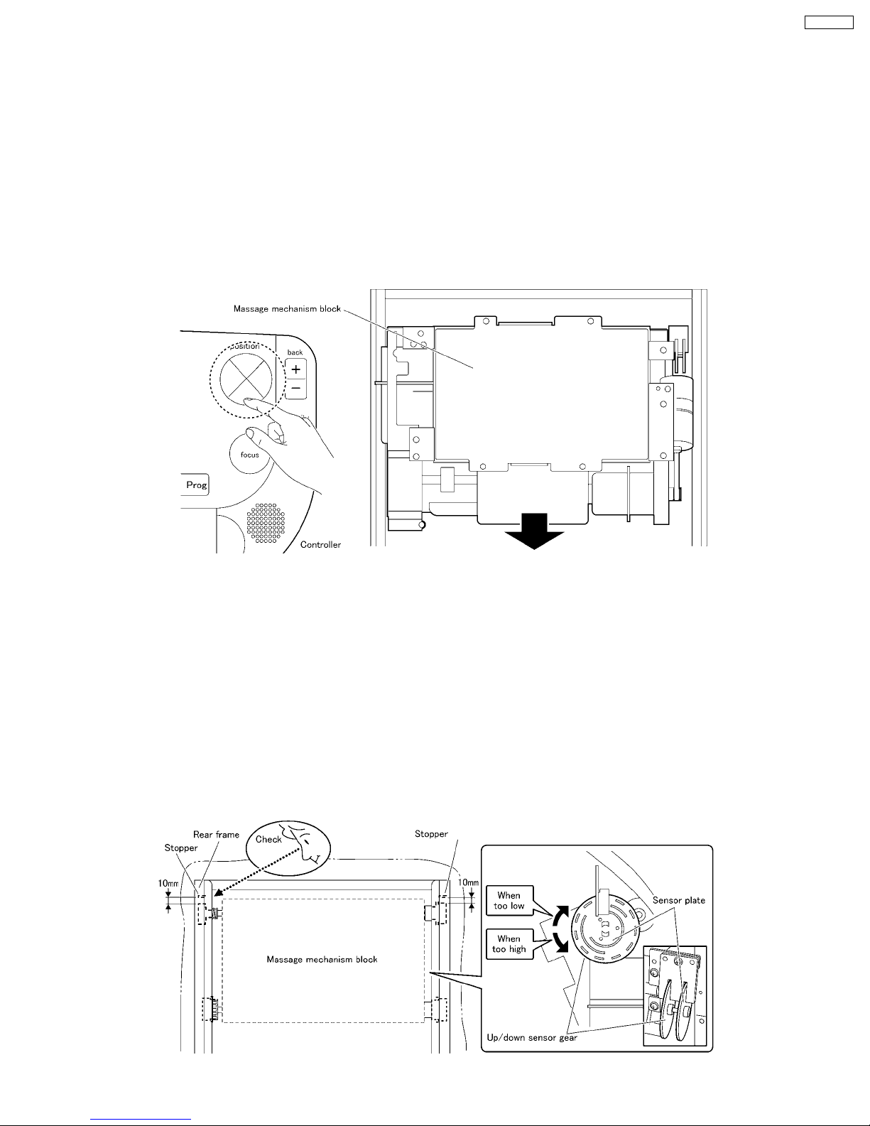
9 MASSAGER UP/DOWN SENSOR GEAR ADJUSTMENT
METHOD
When the massager is removed from the chair, the position of the up/down sensor gear changes, resulting in a change of the
up/down stop position.
When installing the massager on the back frame, be sure to adjust the position with the up/down detection gear.
●●●● Up/down sensor gear position adjustment procedure
1. Before mounting, the massager on the back frame must be moved down to the lowest position by setting the controller manual
operation MASSAGE HEAD ADJUSTMENT button to DOWN.
2. Install Rail pieces (left/right) and screw them with each three screws.
EP3203-U1
3. Make sure that the massager has been mounted horizontally by moving the massager.
*Unless the massager has been mounted horizontally, an abnormal sound or problem may occur.
4. Move it up to the highest position (until the massager stops) by setting the controller manual operation MASSAGE HEAD
ADJUSTMENT button to up.
5. Peeping into the square hole of the back frame, check the position of the massager to adjust.
*One thread of the up/down detection gear gives a stroke change of 4mm.
When the massager has been raised excessively : Turn the up/down sensor gear counterclockwise to adjust.
When the massager has been lowered excessively : Turn the up/down sensor gear clockwise to adjust.
*When adjusting the up/down position, hold the ´Gear´ and adjust it. ( Do not touch the detector board.)
6. While adjusting the distance between the square hole and Guide roller assy. to 10mm, check by using the up/down adjustment
button found on the manual operation panel of the controller.
7. Using the manual operation of the controller, conduct the rolling operation.
13
EP3203-U1
10 DISASSEMBLY AND ASSEMBLY INSTRUCTION
10.1. Removing the Arm rest and the Controller stand
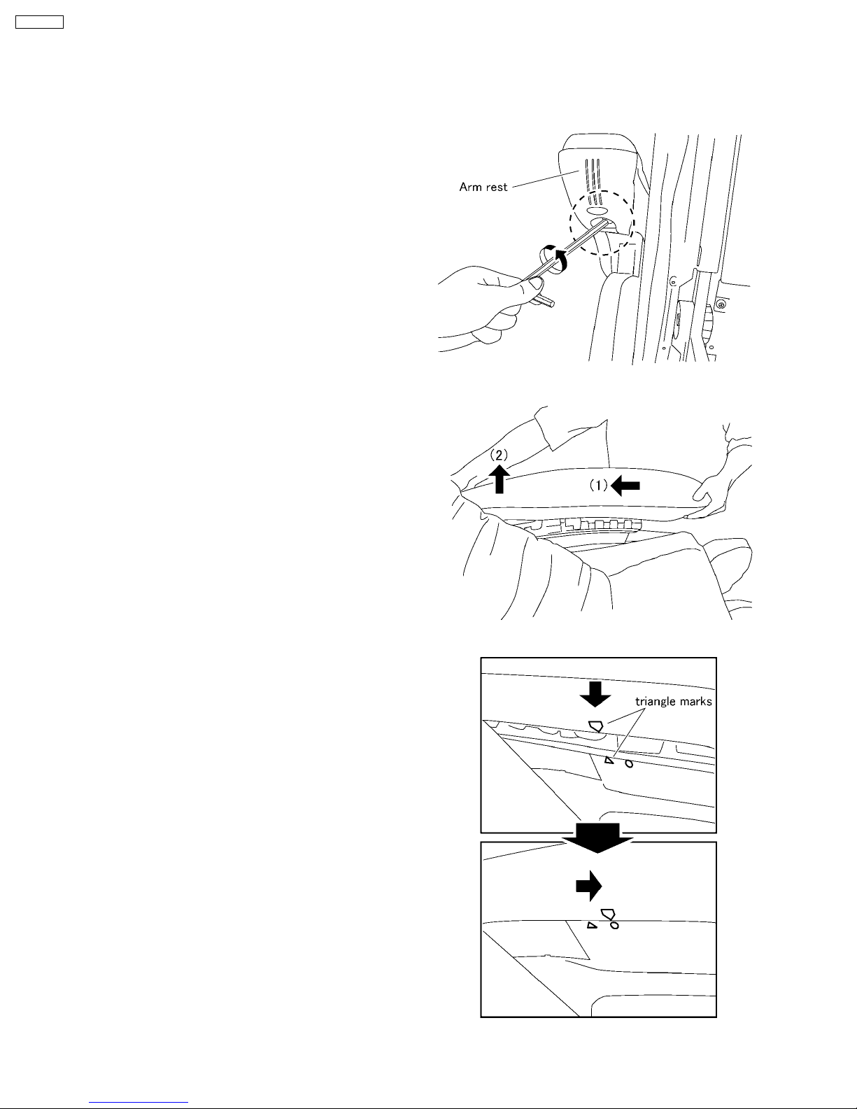
10.1.1. Removing the Arm rest
1. Unscrew a hex screw (4mm) on the bottom of the Arm rest.
2. Pull the Arm rest backward(1) and pull it up(2) and take it
away.
3. You can remove both Arm rests.
Tips of installing
Insert the Arm rest to the Arm rest holder so that both
triangle marks meet each others, and pull the Arm rest
forward to lock.
14
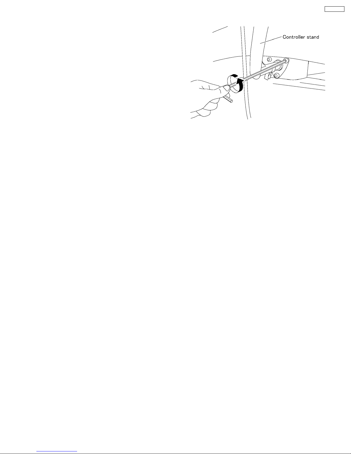
10.1.2. Removing the Controller stand
1. Take off the Controller, and unscrew three Hex
screws(4mm) of the Controller stand.
EP3203-U1
15
EP3203-U1
10.2. Removing the Outside covers
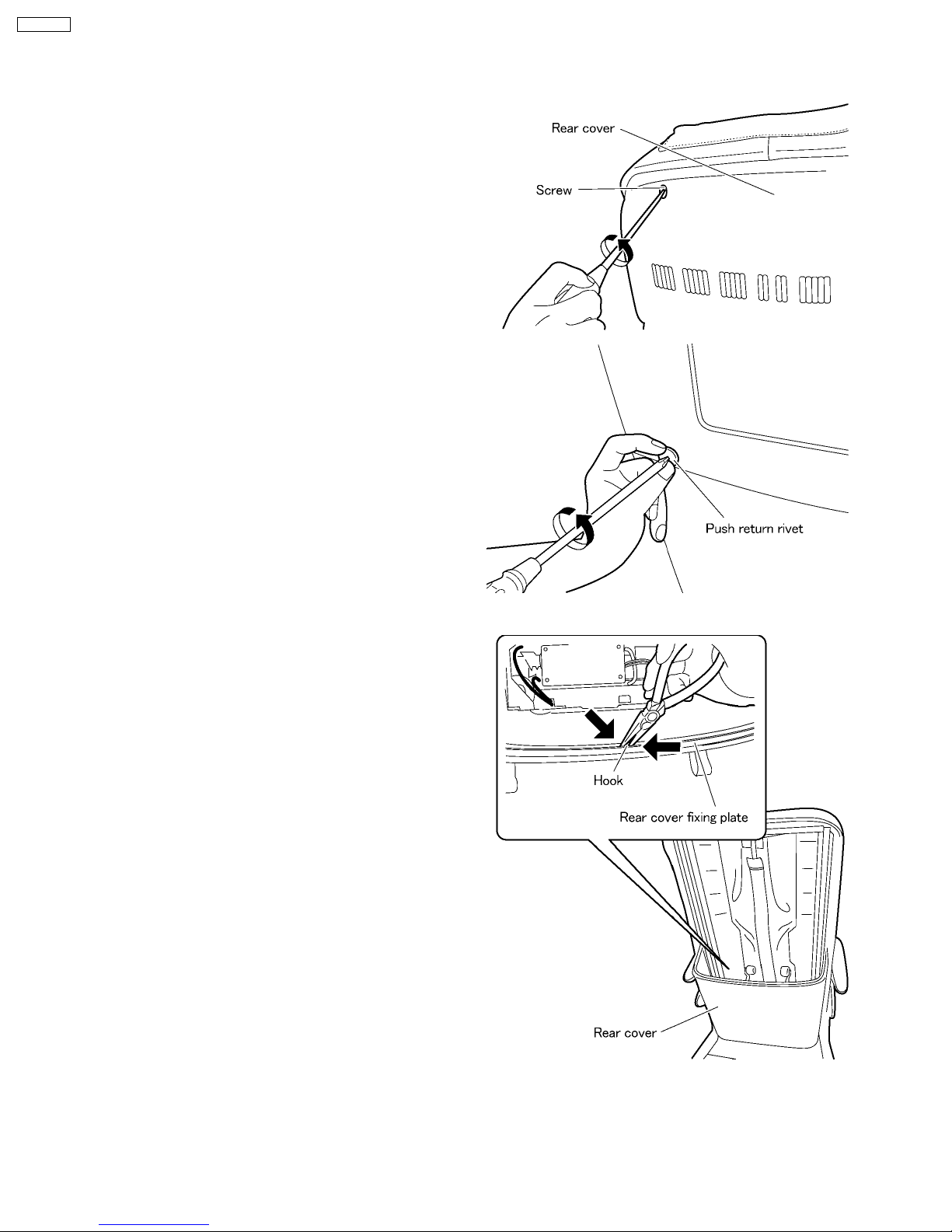
10.2.1. Removing the Rear cover
1. Unscrew two screws at the top of the Rear cover top and
two Push return rivets, and pull it off.
2. Take off the hook with nippers, which fixes the Rear cover
bottom and the Rear cover fixing plate.
16
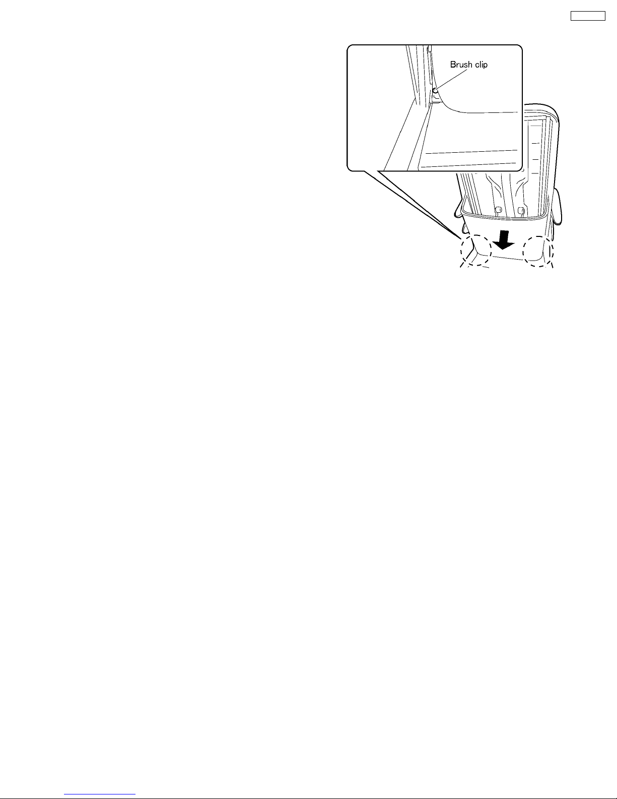
3. Take off two Brush clips on the Rear cover bottom and pull
it off.
EP3203-U1
17
EP3203-U1
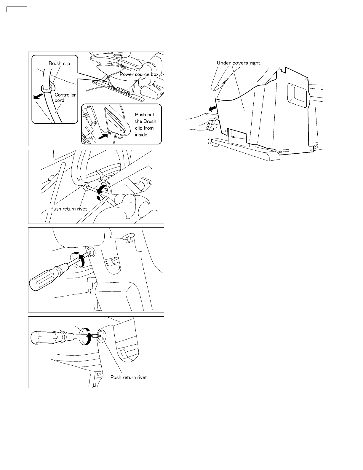
10.2.2. Removing the Under cover
1. Take off 8 push-return-rivets fixing Under cover left/right
and one brush clips (for Under cover right.)
2. Take off the Under covers right/left.
*When you take off the Under cover right, first take off the
parts around the Power source box.
Caution when installing
When installing the Under covers, be sure to confirm
that the Under covers do not pull or crush the Air hoses,
and move the Ottoman to confirm that the Ottoman
does not pull anything.
18
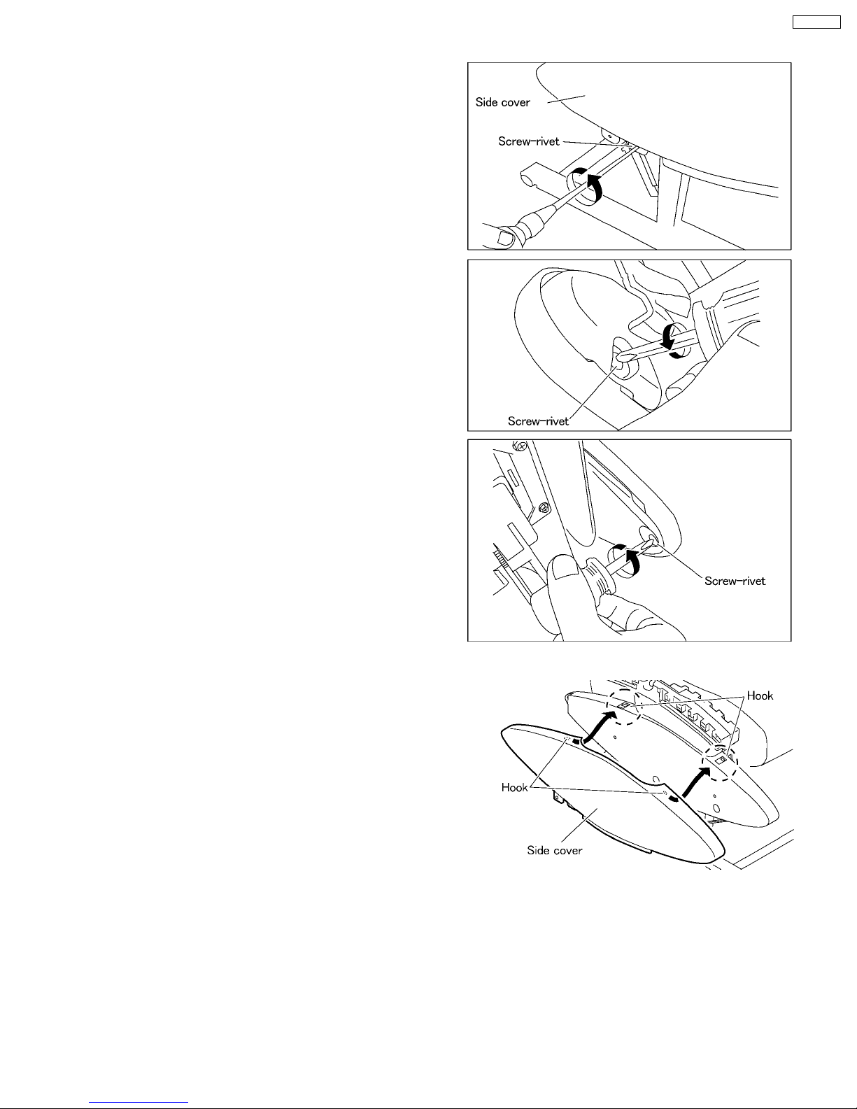
10.2.3. Removing the Side cover
1. Follow the procedure 10.2.1 Removing the Rear cover and
10.2.2. Removing the Under cover.
2. Unscrew three srew-rivets.
EP3203-U1
3. Unhook two hooks on the top of the Side cover and take off
the Side cover.
Caution
When installing the Side cover, first hook two hooks and
then screw screw-rivets.
19
EP3203-U1
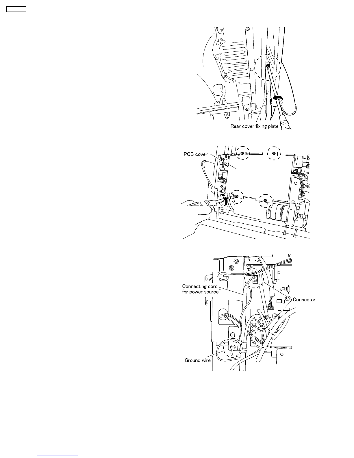
10.3. Removing the Massage mechanism block
Move the Massage mechanism block to the lowest position by
the Upward button. Be sure to lean the Massage chair on
chairs or desk so that the work will be easy.
1. Unscrew four screws on the Rear cover fixing plate.
2. Unscrew four screws of the PC board and remove the PCB
cover.
3. Unscrew a screw fixing the ground wire and disconnect two
connectors.
20
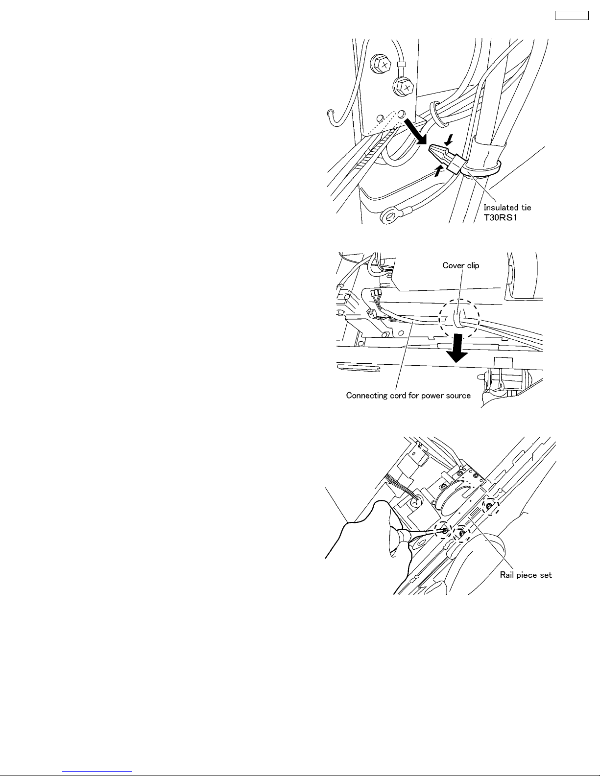
4. Pinch the hook of the Insulated tie and remove it.
5. Remove the Connecting cord for power source from the
Cover clip.
EP3203-U1
6. Remove Rail piece set at both sides.
21
EP3203-U1
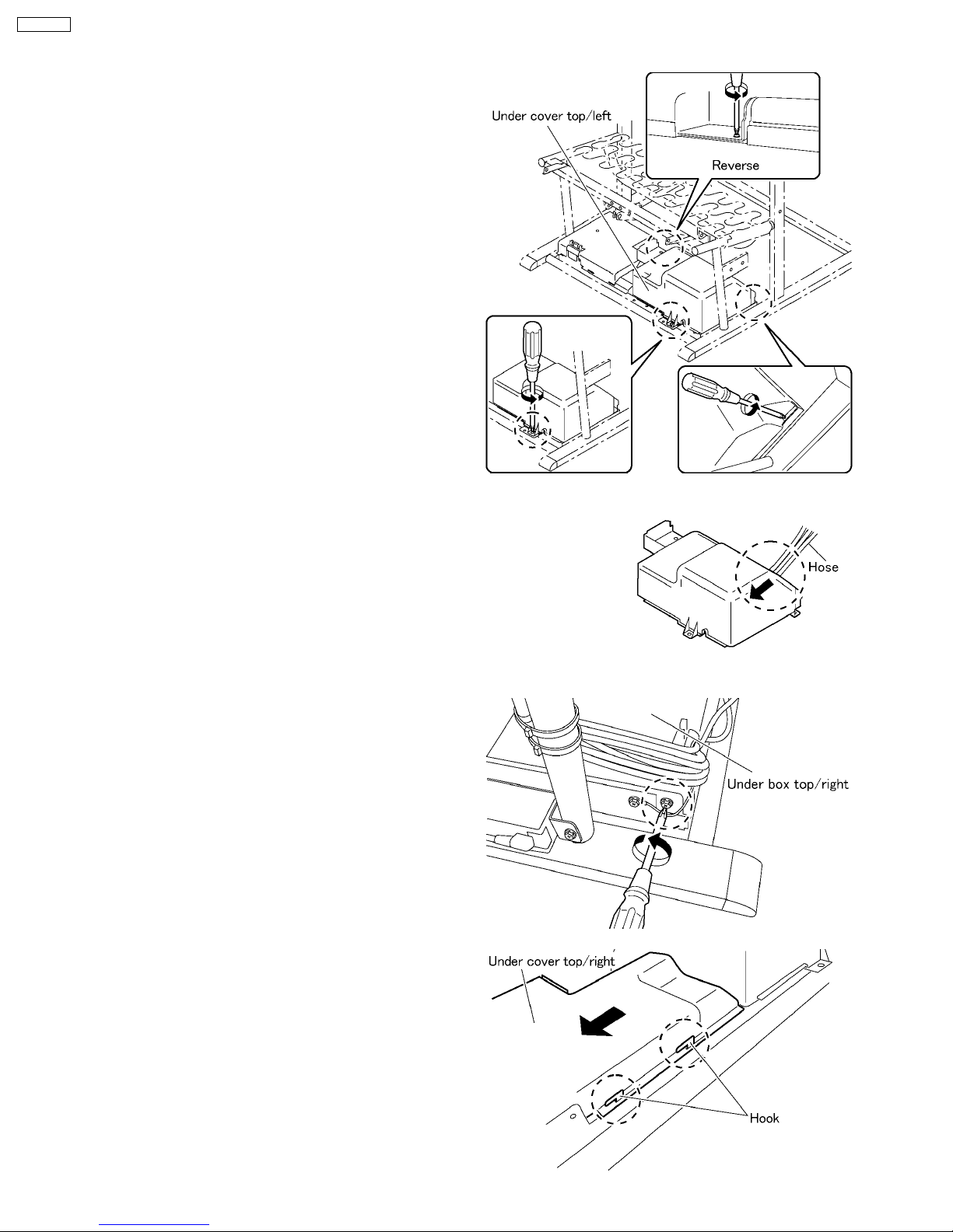
10.4. Removing the Under box and the Under box cover
1. Follow the procedure 10.2.1 Removing the Under cover.
2. Lift the Ottoman and put it on some desk and unscrew three
screws on the Under box top/left and float the Under box
top/left.
3. Disconnect five Ottoman hoses going through the hole on
the Under box top/left and take off the Under cover box
top/left.
4. Unscrew a screw on the Under box top/right and slide the
Under box top/right to the left and unhook four hooks.
22
 Loading...