

Panasonic EP1014-U1 Service Manual
ep1014u1.html
Table Of Contents
COVER
1 Components identification
1.1 Massage lounger
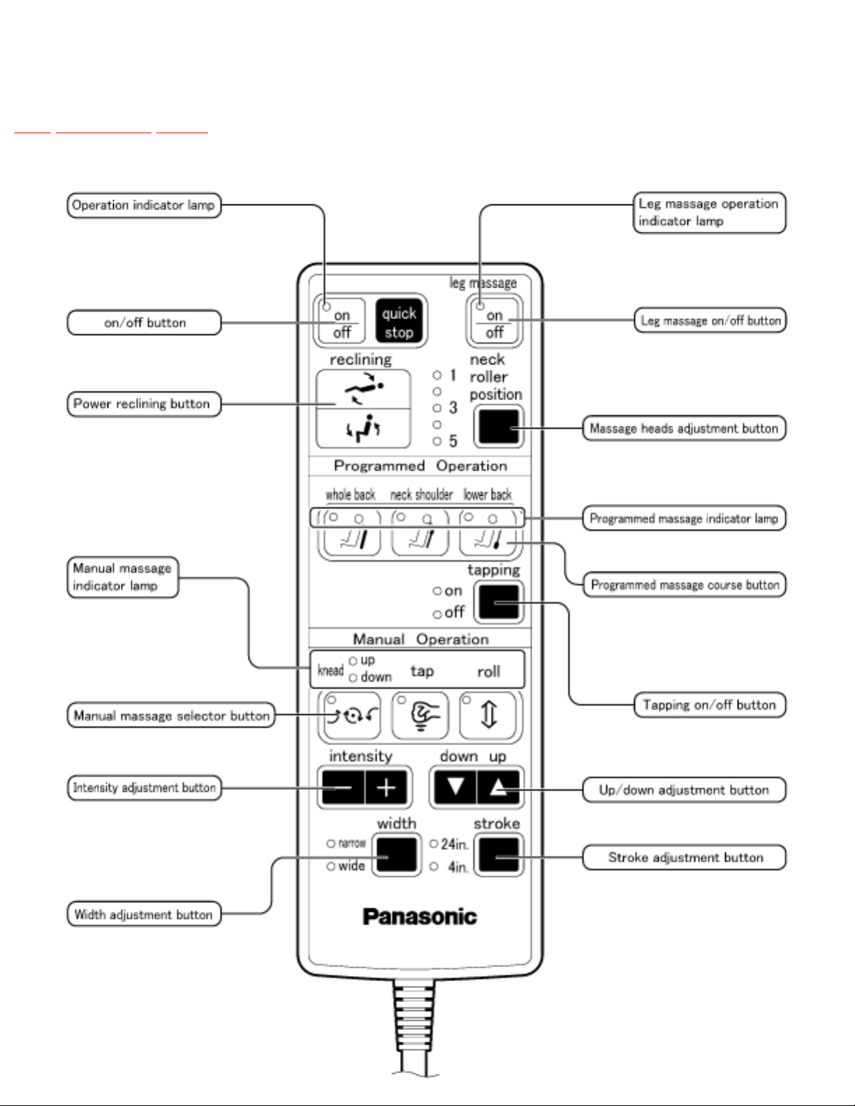
1.2 Controller
2 Massage range (movement range of
massage wheels)
2.1 Upward massage, Downward
massage, Kneading rolling, Regional
kneading rolling
2.2 Tapping, Rolling, Regional rolling,
Tapping rolling, Regional tapping
rolling
3 Turning on the power
3.1 Turning on the power
4 Required tools
5 Actual wiring diagram
6 Display method of massage block
total use time and operation time
7 Motion of the clutch and belt based
on various massager operations.
8 Massager up/down detection
gear adjustment method
9 Removing the massage block
9.1 Removing the rear cover
9.2 Removing the massager
10 Disassembly (massager) and
assembly
10.1 Removing the motor
10.2 Removing the tapping shaft
assembly
10.3 Removing the gear box
10.4 Removing the massage wheel
unit set (right, left)
10.5 Removing and mounting the
up/down shaft bolt
10.5.1 Removing
10.5.2 Mounting
10.5.3
Service Manual
TOP NEXT
ORDER NO.HPD0204U00C1
MASSAGE LOUNGER
● EP1014-U1
SPECIFICATIONS
Power source : 120V AC, 60Hz
Power consumption : 200W
Kneading speed : Approx. 28 times/min.
Tapping speed : Approx. 500 times/min.(per side)
Rolling massage speed : Approx. 1 cycle every 37 sec.
Massaging width : Shoulder/lower back section : Approx. 2-15/16 in. (75mm)
Back rolling width/tapping width : Narrow : Approx. 3-5/16 in. (85mm)/: Wide : Approx. 4-5/16 in. (110mm)
http://202.224.189.178/~sgml/viewing/EP1014-U1/NA/SVC/PVAccel.html (1 of 2) [12/6/2003 9:48:19 AM]
ep1014u1.html
11 Cord arrangement of the
connecting cord for power supply and
the connecting cord for controller.
12 Arranging massage block lead
wires
13 Disassembly instruction ( Cosmetic
part and chair construction)
13.1 Seat Cushion
13.2 Massage Wheel Cover
13.3 Under Cover
13.4 Caster Pipe Cover
13.5 Power Source Switch Block
13.6 Circuit Board B
13.7 Roller ottoman
13.8 Ottoman Power Lift Unit
14 Other
14.1 Grease use
14.2 Examination after inspection and
repairing
14.3 Q&A
14.4 Instructions for trouble shooting
in response to a customer's claim.
15 Trouble shooting
16 Exploded view
17 Replacement parts list for EP1014-
U1
Massage heads up/down travel : Approx. 23-5/8 in. (600mm)
Regional back rolling : Automatic repetition within approx. 4-3/4 in. (120mm) range
Intensity adjustment : Adjusts massage head protrusion steplessly within approx. 1-3/4 in.(45mm) range
Shoulder position adjustment : 5 steps
Automatic shut-off : Approx. 15 min.
Dimensions (H x W x D) :•Not reclined and leg rest retracted : 41-11/32X34-41/64X40-35/64 in.(1050X880X1030mm)/ •Reclined and leg rest extended : 29-9/64X34-
41/64X68-7/64in.(740X880X1730mm)
Reclining angle : Approx. 123° to 160°
Weight : 121 lbs. (55kg)
Accessories : Back cushion, Headrest, Cushion pad
Maximum user weight : 264lbs.(120kg).
© 2002 Matsushita Electric Works, Ltd. All rights reserved. Unauthorized copying and distribution is a violation of law.
TOP NEXT
http://202.224.189.178/~sgml/viewing/EP1014-U1/NA/SVC/PVAccel.html (2 of 2) [12/6/2003 9:48:19 AM]

http://202.224.189.178/~sgml/viewing/EP1014-U1/NA/SVC/ep1014u1.html
Table Of Contents
COVER
1 Components identification
1.1 Massage lounger
1.2 Controller
2 Massage range (movement range of massage wheels)
2.1 Upward massage, Downward massage, Kneading rolling, Regional kneading rolling
2.2 Tapping, Rolling, Regional rolling, Tapping rolling, Regional tapping rolling
3 Turning on the power
3.1 Turning on the power
4 Required tools
5 Actual wiring diagram
6 Display method of massage block total use time and operation time
7 Motion of the clutch and belt based on various massager operations.
8 Massager up/down detection gear adjustment method
9 Removing the massage block
9.1 Removing the rear cover
9.2 Removing the massager
10 Disassembly (massager) and assembly
http://202.224.189.178/~sgml/viewing/EP1014-U1/NA/SVC/ep1014u1.html (1 of 3) [12/6/2003 9:48:20 AM]

http://202.224.189.178/~sgml/viewing/EP1014-U1/NA/SVC/ep1014u1.html
10.1 Removing the motor
10.2 Removing the tapping shaft assembly
10.3 Removing the gear box
10.4 Removing the massage wheel unit set (right, left)
10.5 Removing and mounting the up/down shaft bolt
10.5.1 Removing
10.5.2 Mounting
10.5.3
11 Cord arrangement of the connecting cord for power supply and the connecting cord for controller.
12 Arranging massage block lead wires
13 Disassembly instruction ( Cosmetic part and chair construction)
13.1 Seat Cushion
13.2 Massage Wheel Cover
13.3 Under Cover
13.4 Caster Pipe Cover
13.5 Power Source Switch Block
13.6 Circuit Board B
13.7 Roller ottoman
13.8 Ottoman Power Lift Unit
http://202.224.189.178/~sgml/viewing/EP1014-U1/NA/SVC/ep1014u1.html (2 of 3) [12/6/2003 9:48:20 AM]

http://202.224.189.178/~sgml/viewing/EP1014-U1/NA/SVC/ep1014u1.html
14 Other
14.1 Grease use
14.2 Examination after inspection and repairing
14.3 Q&A
14.4 Instructions for trouble shooting in response to a customer´s claim.
15 Trouble shooting
16 Exploded view
17 Replacement parts list for EP1014-U1
http://202.224.189.178/~sgml/viewing/EP1014-U1/NA/SVC/ep1014u1.html (3 of 3) [12/6/2003 9:48:20 AM]
http://202.224.189.178/~sgml/viewing/EP1014-U1/NA/SVC/s0000000000.html
Service Manual
TOP NEXT
ORDER NO.HPD0204U00C1
MASSAGE LOUNGER
● EP1014-U1
SPECIFICATIONS
Power source : 120V AC, 60Hz
Power consumption : 200W
Kneading speed : Approx. 28 times/min.
Tapping speed : Approx. 500 times/min.(per side)
Rolling massage speed : Approx. 1 cycle every 37 sec.
Massaging width : Shoulder/lower back section : Approx. 2-15/16 in. (75mm)
Back rolling width/tapping width : Narrow : Approx. 3-5/16 in. (85mm)/: Wide : Approx. 4-5/16 in. (110mm)
Massage heads up/down travel : Approx. 23-5/8 in. (600mm)
Regional back rolling : Automatic repetition within approx. 4-3/4 in. (120mm) range
Intensity adjustment : Adjusts massage head protrusion steplessly within approx. 1-3/4 in.(45mm) range
Shoulder position adjustment : 5 steps
Automatic shut-off : Approx. 15 min.
Dimensions (H x W x D) :•Not reclined and leg rest retracted : 41-11/32X34-41/64X40-35/64 in.(1050X880X1030mm)/ •Reclined and leg rest extended : 29-9/64X34-
41/64X68-7/64in.(740X880X1730mm)
Reclining angle : Approx. 123° to 160°
Weight : 121 lbs. (55kg)
Accessories : Back cushion, Headrest, Cushion pad
http://202.224.189.178/~sgml/viewing/EP1014-U1/NA/SVC/s0000000000.html (1 of 2) [12/6/2003 9:48:21 AM]

http://202.224.189.178/~sgml/viewing/EP1014-U1/NA/SVC/s0000000000.html
Maximum user weight : 264lbs.(120kg).
© 2002 Matsushita Electric Works, Ltd. All rights reserved. Unauthorized copying and distribution is a violation of law.
TOP NEXT
http://202.224.189.178/~sgml/viewing/EP1014-U1/NA/SVC/s0000000000.html (2 of 2) [12/6/2003 9:48:21 AM]

http://202.224.189.178/~sgml/viewing/EP1014-U1/NA/SVC/s0100000000x.html
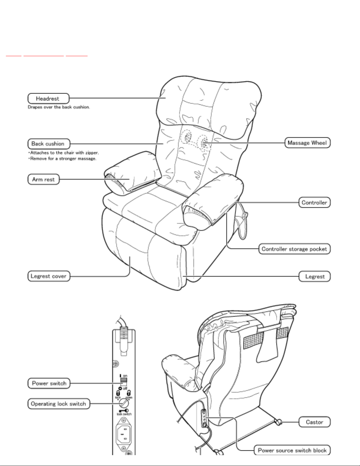
1 Components identification
TOP PREVIOUS NEXT
1.1 Massage lounger
1.2 Controller
TOP PREVIOUS NEXT
http://202.224.189.178/~sgml/viewing/EP1014-U1/NA/SVC/s0100000000x.html [12/6/2003 9:48:23 AM]
http://202.224.189.178/~sgml/viewing/EP1014-U1/NA/SVC/s0101000000.html
1.1 Massage lounger
TOP PREVIOUS NEXT
http://202.224.189.178/~sgml/viewing/EP1014-U1/NA/SVC/s0101000000.html (1 of 2) [12/6/2003 9:48:25 AM]

http://202.224.189.178/~sgml/viewing/EP1014-U1/NA/SVC/s0101000000.html
TOP PREVIOUS NEXT
http://202.224.189.178/~sgml/viewing/EP1014-U1/NA/SVC/s0101000000.html (2 of 2) [12/6/2003 9:48:25 AM]
http://202.224.189.178/~sgml/viewing/EP1014-U1/NA/SVC/s0102000000.html
1.2 Controller
TOP PREVIOUS NEXT
http://202.224.189.178/~sgml/viewing/EP1014-U1/NA/SVC/s0102000000.html (1 of 2) [12/6/2003 9:48:27 AM]

http://202.224.189.178/~sgml/viewing/EP1014-U1/NA/SVC/s0102000000.html
TOP PREVIOUS NEXT
http://202.224.189.178/~sgml/viewing/EP1014-U1/NA/SVC/s0102000000.html (2 of 2) [12/6/2003 9:48:27 AM]

http://202.224.189.178/~sgml/viewing/EP1014-U1/NA/SVC/s0200000000x.html
2 Massage range (movement range of
massage wheels)
TOP PREVIOUS NEXT
2.1 Upward massage, Downward massage, Kneading rolling, Regional kneading rolling
2.2 Tapping, Rolling, Regional rolling, Tapping rolling, Regional tapping rolling
TOP PREVIOUS NEXT
http://202.224.189.178/~sgml/viewing/EP1014-U1/NA/SVC/s0200000000x.html [12/6/2003 9:48:27 AM]

http://202.224.189.178/~sgml/viewing/EP1014-U1/NA/SVC/s0201000000.html
2.1 Upward massage, Downward
massage, Kneading rolling, Regional
kneading rolling
TOP PREVIOUS NEXT
Width cannot be adjusted
Neck to waist : width 75mm (minimum)
Intensity adjustment
Upward and downward massage (from gentle to strong) :45mm-wide adjustability where massage heads
push out toward body as intensity increases.Others (from gentle to strong) :15mm-wide adjustability
where massage heads push out toward body as intensityincreases.
TOP PREVIOUS NEXT
http://202.224.189.178/~sgml/viewing/EP1014-U1/NA/SVC/s0201000000.html [12/6/2003 9:48:28 AM]
http://202.224.189.178/~sgml/viewing/EP1014-U1/NA/SVC/s0202000000.html
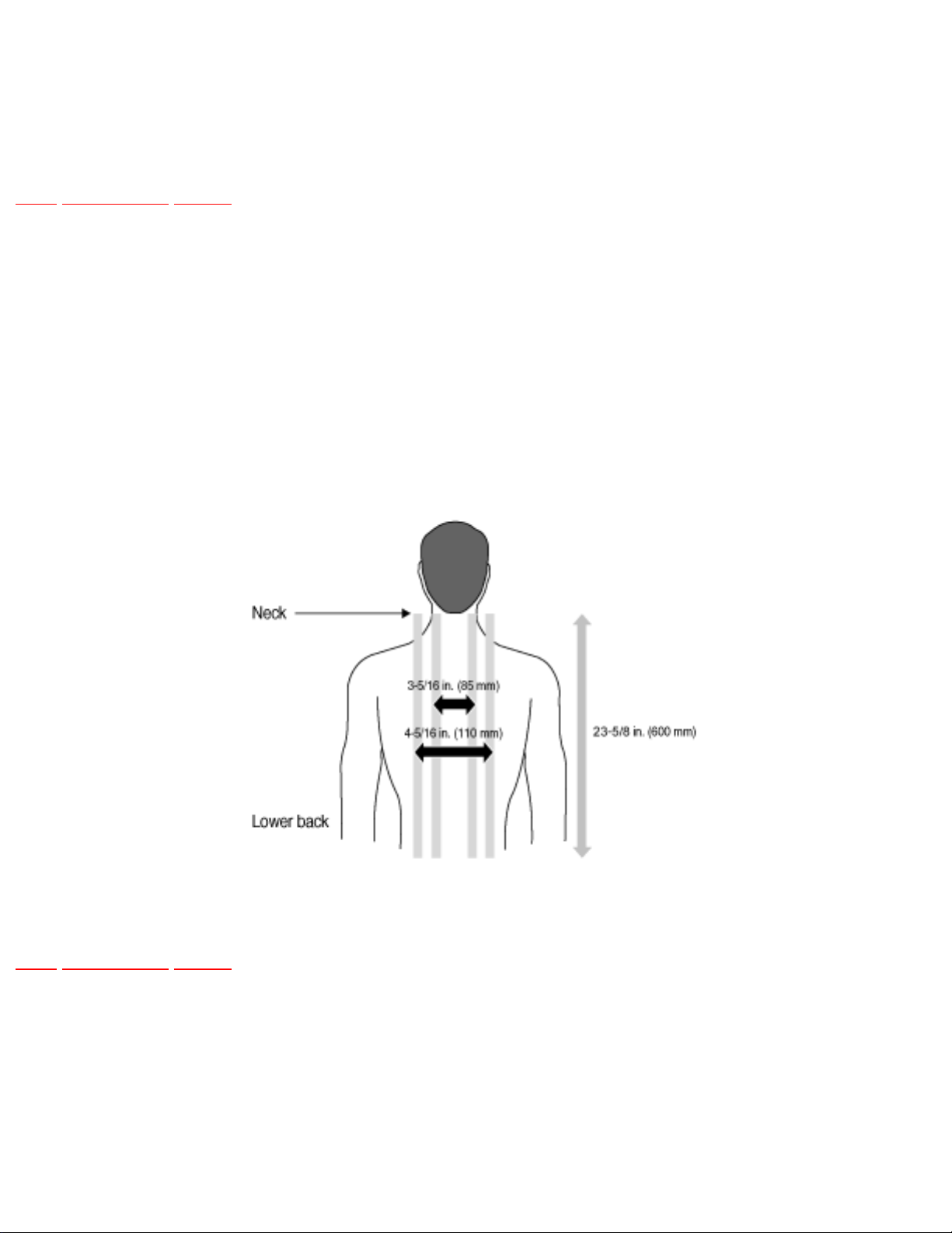
2.2 Tapping, Rolling, Regional rolling,
Tapping rolling, Regional tapping rolling
TOP PREVIOUS NEXT
Width adjustment
Neck to waist : Massage range width : 3-5/16 in. or 4-5/16 in. (85mm or 110mm)
Intensity adjustment
Tapping : 45mm-wide adjustability where massage heads push out toward body as intensity increases.
Others : 15mm-wide adjustability where massage heads push out toward body as intensity increases.
TOP PREVIOUS NEXT
http://202.224.189.178/~sgml/viewing/EP1014-U1/NA/SVC/s0202000000.html [12/6/2003 9:48:29 AM]

http://202.224.189.178/~sgml/viewing/EP1014-U1/NA/SVC/s0300000000x.html
3 Turning on the power
TOP PREVIOUS NEXT
3.1 Turning on the power
TOP PREVIOUS NEXT
http://202.224.189.178/~sgml/viewing/EP1014-U1/NA/SVC/s0300000000x.html [12/6/2003 9:48:30 AM]

http://202.224.189.178/~sgml/viewing/EP1014-U1/NA/SVC/s0301000000.html
3.1 Turning on the power
TOP PREVIOUS NEXT
Timer
When the on/off button is pushed, a timer begins to prevent overuse. After approximately 15 minutes,
time expires and the massage wheel goes into strage position.
TOP PREVIOUS NEXT
http://202.224.189.178/~sgml/viewing/EP1014-U1/NA/SVC/s0301000000.html [12/6/2003 9:48:32 AM]
http://202.224.189.178/~sgml/viewing/EP1014-U1/NA/SVC/s0400000000x.html
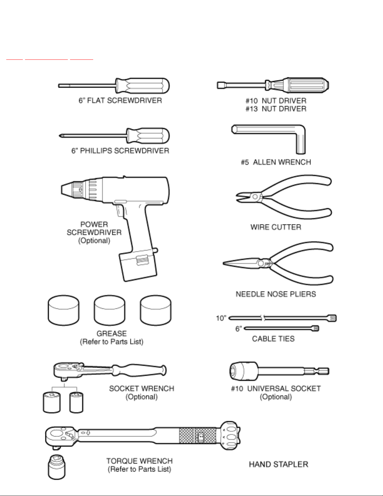
4 Required tools
TOP PREVIOUS NEXT
http://202.224.189.178/~sgml/viewing/EP1014-U1/NA/SVC/s0400000000x.html (1 of 2) [12/6/2003 9:48:34 AM]

http://202.224.189.178/~sgml/viewing/EP1014-U1/NA/SVC/s0400000000x.html
TOP PREVIOUS NEXT
http://202.224.189.178/~sgml/viewing/EP1014-U1/NA/SVC/s0400000000x.html (2 of 2) [12/6/2003 9:48:34 AM]
http://202.224.189.178/~sgml/viewing/EP1014-U1/NA/SVC/s0500000000x.html
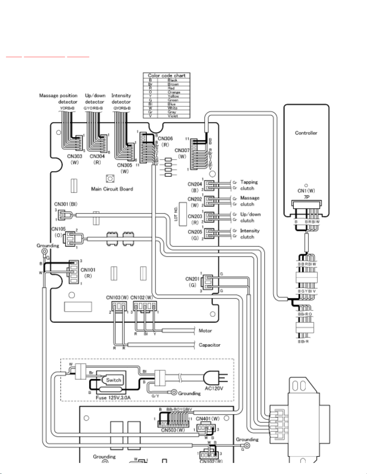
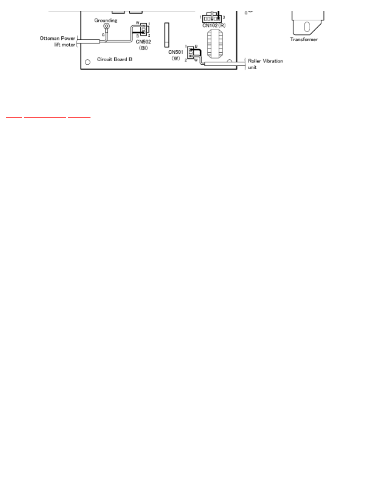
5 Actual wiring diagram
TOP PREVIOUS NEXT
http://202.224.189.178/~sgml/viewing/EP1014-U1/NA/SVC/s0500000000x.html (1 of 2) [12/6/2003 9:48:36 AM]
http://202.224.189.178/~sgml/viewing/EP1014-U1/NA/SVC/s0500000000x.html
TOP PREVIOUS NEXT
http://202.224.189.178/~sgml/viewing/EP1014-U1/NA/SVC/s0500000000x.html (2 of 2) [12/6/2003 9:48:36 AM]
http://202.224.189.178/~sgml/viewing/EP1014-U1/NA/SVC/s0600000000x.html
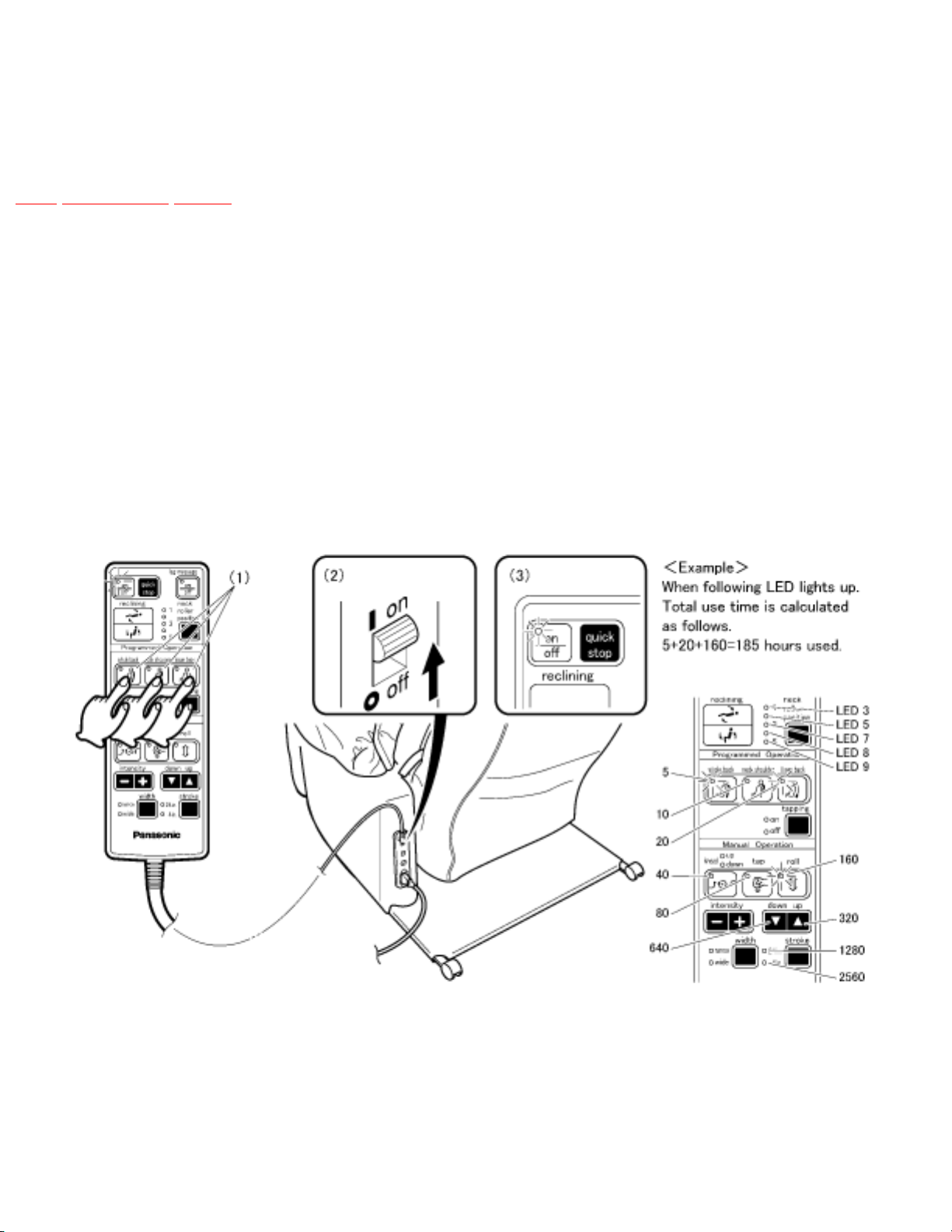
6 Display method of massage block total
use time and operation time
TOP PREVIOUS NEXT
Total use time
While pushing the whole back, neck shoulder and lower back mode programmed operation buttons
simultaneiously, turn on the power switch and continue to hold the buttons for approximately 5 seconds.
Release after the on/off LED lights up.
*When replacing the Main Circuit PCB, the use time is counted to zero because the use time is memoried
in Main Circuit PCB.
*When pushing on/off button, the operation returns to normal mode.
Display method
Display it by utilizing LEDs of controller.
Time display of 5 - 5115 hours possible.
http://202.224.189.178/~sgml/viewing/EP1014-U1/NA/SVC/s0600000000x.html (1 of 2) [12/6/2003 9:48:38 AM]
http://202.224.189.178/~sgml/viewing/EP1014-U1/NA/SVC/s0600000000x.html
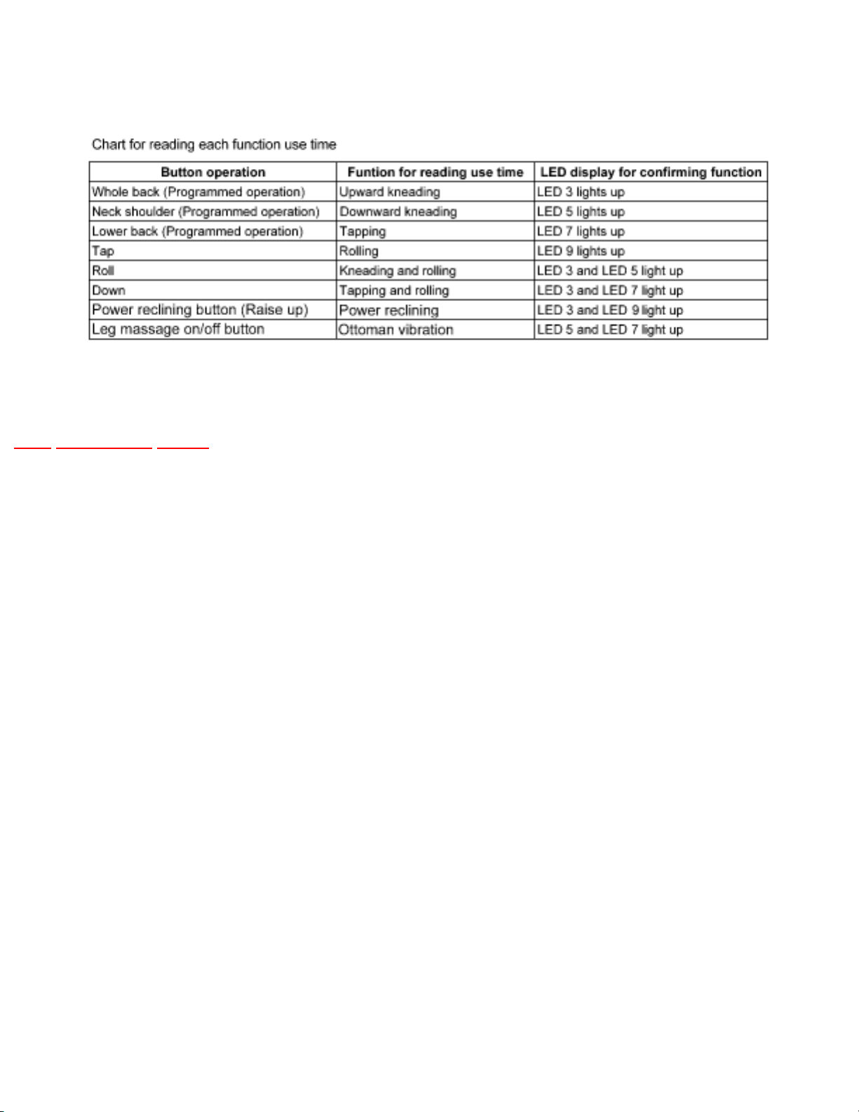
To read the each operation function.After reading the total use time and push the following button, you
can read the each operation funtion use time as same display method of total use time.
TOP PREVIOUS NEXT
http://202.224.189.178/~sgml/viewing/EP1014-U1/NA/SVC/s0600000000x.html (2 of 2) [12/6/2003 9:48:38 AM]
http://202.224.189.178/~sgml/viewing/EP1014-U1/NA/SVC/s0700000000x.html
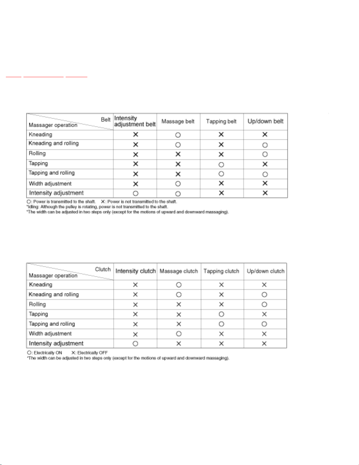
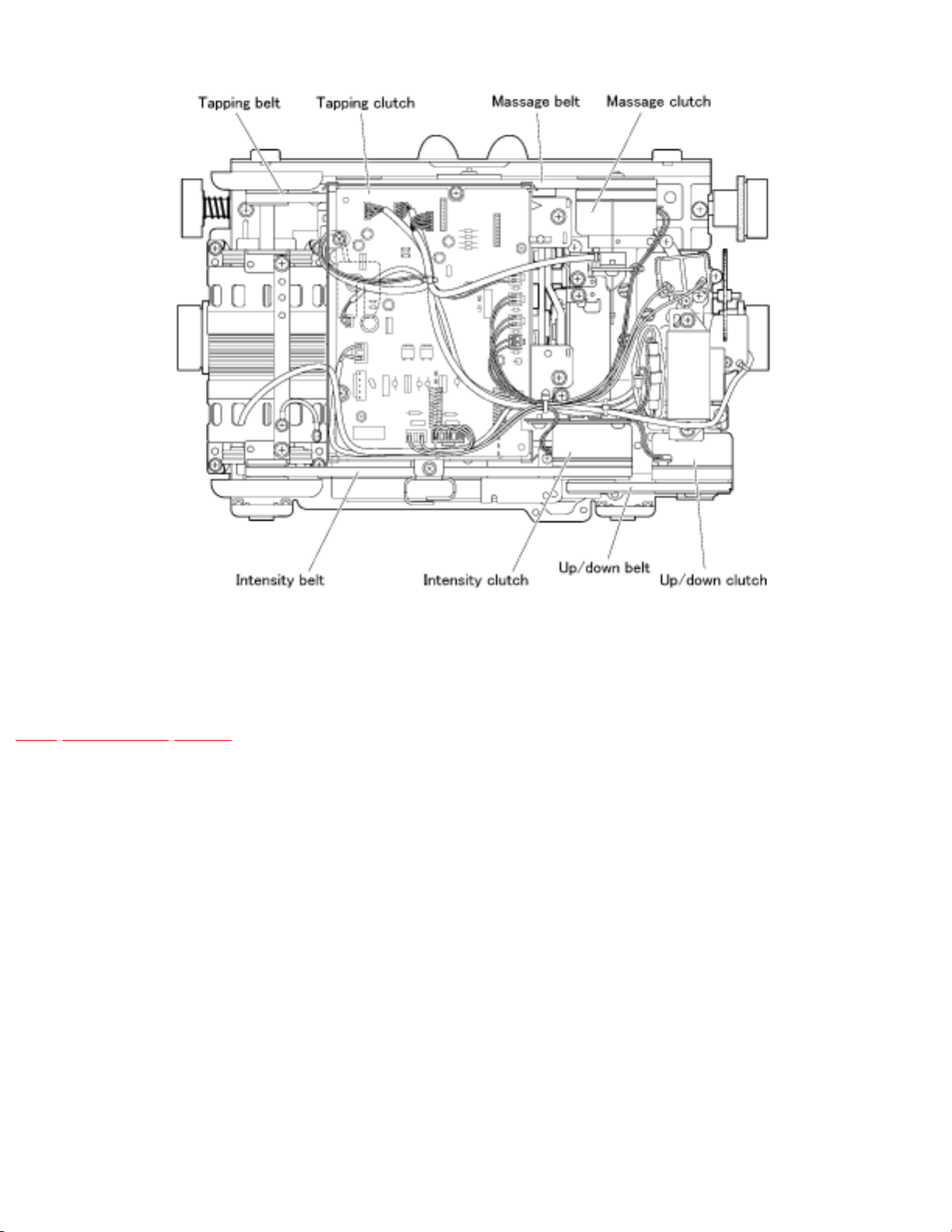
7 Motion of the clutch and belt based on
various massager operations.
TOP PREVIOUS NEXT
Massager operation and belt motion
Massager operation and clutch motion
http://202.224.189.178/~sgml/viewing/EP1014-U1/NA/SVC/s0700000000x.html (1 of 2) [12/6/2003 9:48:40 AM]
http://202.224.189.178/~sgml/viewing/EP1014-U1/NA/SVC/s0700000000x.html
TOP PREVIOUS NEXT
http://202.224.189.178/~sgml/viewing/EP1014-U1/NA/SVC/s0700000000x.html (2 of 2) [12/6/2003 9:48:40 AM]

http://202.224.189.178/~sgml/viewing/EP1014-U1/NA/SVC/s0800000000x.html
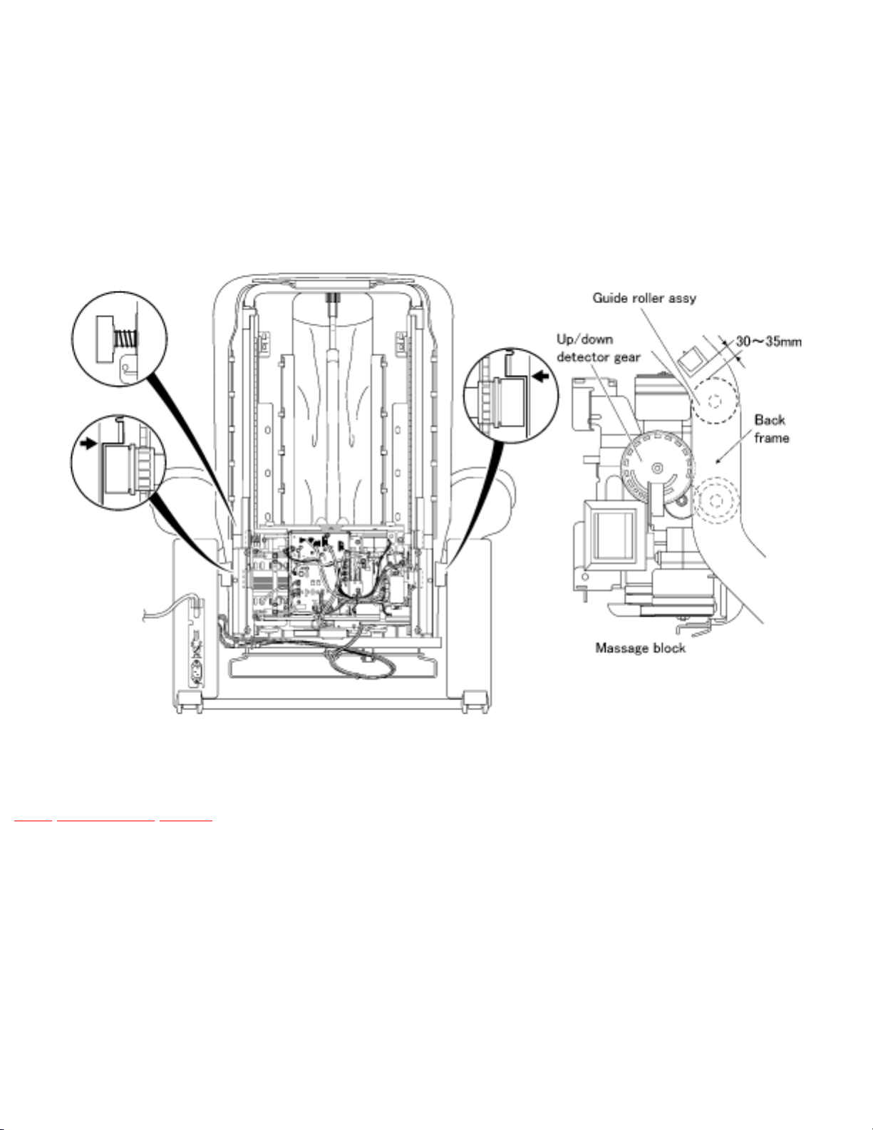
8 Massager up/down detection gear
adjustment method
TOP PREVIOUS NEXT
When the massager is removed from the chair, the position of the up/down detection gear changes,
resulting in a change of the up/down stop position.
When installing the massager on the back frame, be sure to adjust the position with the up/down
detection gear.
• Up/down detection gear position adjustment procedure
To make an adjustment, refer to the massager removing method (the back frame is tilted from the chair).
1. Before mounting, the massager on the back frame must be moved down to the lowest position by
setting the controller manual operation UP/DOWN button to DOWN.
2. Mount the massager on the lowest position of the back frame.
3. Turn the hex nut M6 counterclockwise and move the massager upward.
4. Make sure that the massager has been mounted horizontally by moving the massager to the
position shown in the Figure.
*Unless the massager has been mounted horizontally, an abnormal sound or problem may occur.
5. Move it up to the highest position(until the massager stops) by setting the controller manual
operation UP/DOWN button to UP.
6. Peeping into the square hole of the back frame, check the position of the massager to adjust.
*One thread of the up/down detection gear gives a stroke change of 4mm.
When the massager has been raised excessively : Turn the up/down detection gear clockwise to
adjust.
When the massager has been lowered excessively : Turn the up/down detection gear
counterclockwise to adjust.
http://202.224.189.178/~sgml/viewing/EP1014-U1/NA/SVC/s0800000000x.html (1 of 2) [12/6/2003 9:48:42 AM]
http://202.224.189.178/~sgml/viewing/EP1014-U1/NA/SVC/s0800000000x.html
While adjusting the distance between the square hole and Guide roller assy. to 30~35mm, check
by using the up/down adjustment button found on the manual operation panel of the controller.
7. Install the rail piece A and B, and tighten uniformly the set screws (left and right, 3 pcs. each).
8. Using the manual operation of the controller, conduct the rolling operation. Set the massage heads
adjustment switch to level 1, and check the up/down stroke.
TOP PREVIOUS NEXT
http://202.224.189.178/~sgml/viewing/EP1014-U1/NA/SVC/s0800000000x.html (2 of 2) [12/6/2003 9:48:42 AM]

http://202.224.189.178/~sgml/viewing/EP1014-U1/NA/SVC/s0900000000x.html
9 Removing the massage block
TOP PREVIOUS NEXT
9.1 Removing the rear cover
9.2 Removing the massager
TOP PREVIOUS NEXT
http://202.224.189.178/~sgml/viewing/EP1014-U1/NA/SVC/s0900000000x.html [12/6/2003 9:48:43 AM]
http://202.224.189.178/~sgml/viewing/EP1014-U1/NA/SVC/s0901000000.html
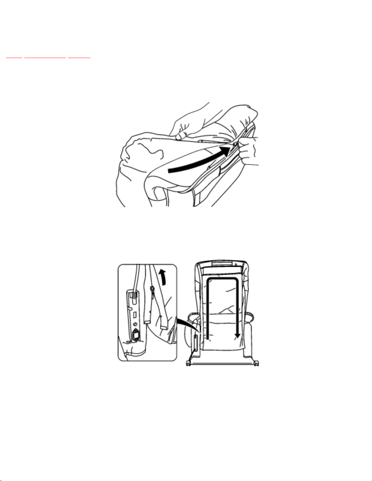
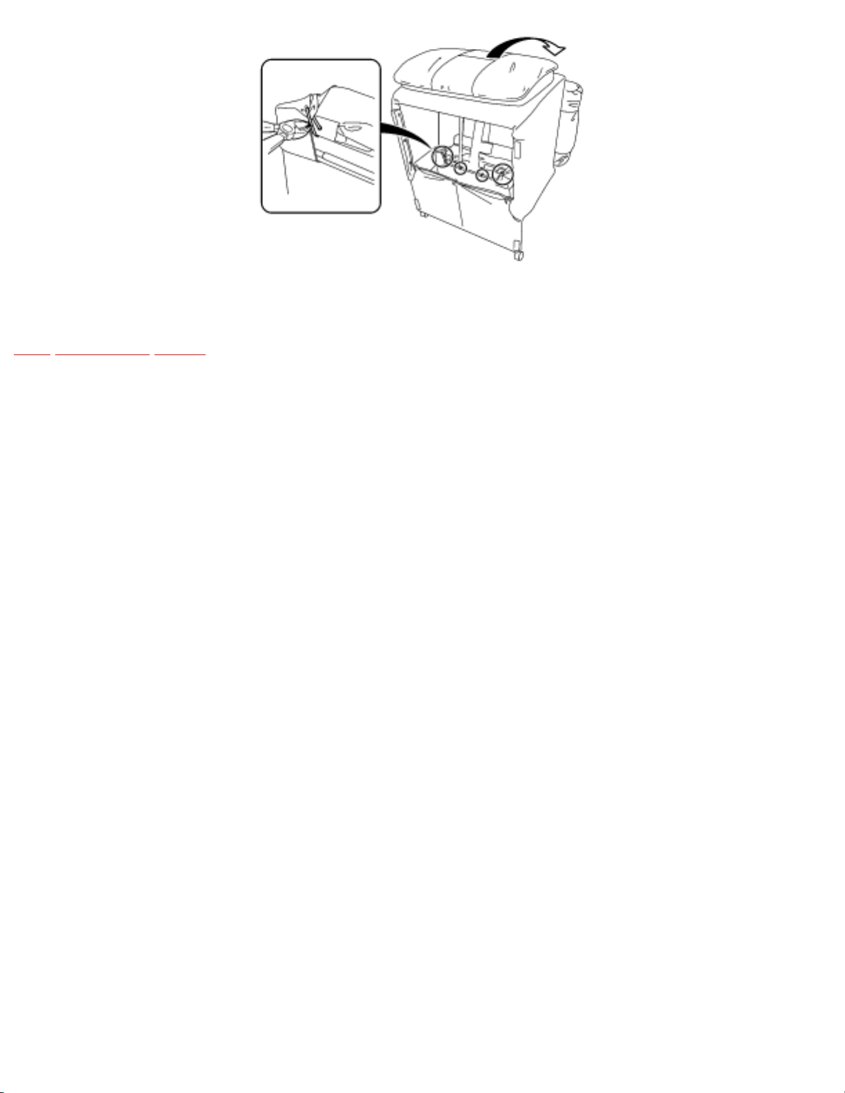
9.1 Removing the rear cover
TOP PREVIOUS NEXT
1. Unzip the back cushion zipper and remove the back /cushion.
2. Unzip the rear cover fastener from the bottom of left side.
3. Pull the chair down backward and cut insulated ties and remove the plastic clip.
http://202.224.189.178/~sgml/viewing/EP1014-U1/NA/SVC/s0901000000.html (1 of 2) [12/6/2003 9:48:45 AM]
http://202.224.189.178/~sgml/viewing/EP1014-U1/NA/SVC/s0901000000.html
TOP PREVIOUS NEXT
http://202.224.189.178/~sgml/viewing/EP1014-U1/NA/SVC/s0901000000.html (2 of 2) [12/6/2003 9:48:45 AM]
 Loading...