How it Works
Log In / Sign Up
Buy Points
How it Works
FAQ
Contact Us
Questions and Suggestions
Users
Panasonic
Loading...
E
Easa-Phone VA-208
3
Easa-Phone VA-412
Easy-Phone Auto-Logic KX-T1450
Easy-Phone Auto-Logic KX-T1451
Easy-Phone KX-T4000
EB
EB-3610
2
EB-3650
2
EB-3651
EB-3652
EB-3901
6
EB-A100
3
EB-A101
EB-A102
4
EB-A200
EB-A210
EB-A 3,3U 50
EB-A500
2
EB-BL600
4
EB-BM600
4
EB-BS600
4
EB-CA600
4
EB-CD400
EB-CD400A
EB-CD600
4
EB-CR500
3
EB-CR600
5
EB-G300S
EB-G350S
EB-G400Z
EB-G450
3
EB-G50
8
EB-G500
3
EB-G500 series
EB-G51
3
EB-G51E
4
EB-G51M
6
EB-G51U
2
EB-G520
2
EB-G60
9
EB-G600
9
EB-G60U
EB-G70
4
EB-GD30
7
EB-GD35
7
EB-GD35C
EB-GD50
9
EB-GD52
8
EB-GD55
7
EB-GD55C
EB-GD67
9
EB-GD68
2
EB-GD70
4
EB-GD75
10
EB-GD75C
EB-GD76
2
EB-GD87
14
EB-GD90
10
EB-GD92
9
EB-GD92C
2
EB-GD93
9
EB-GD95
10
EB-GD95C
EB-GD96
2
EB-GU87
EB-H64
EB-H65
EB-H655
EB-H65S
EB-H70
EB-H705
EB-H705S
EB-H7071
EB-H7071S
EB-H7072
EB-H7072S
EB-H7075
EB-H7075S
EB-H70S
EB-HF20
EB-HF20E
EB-HF450Z
2
EB-HF500Z
EB-HF501Z
2
EB-HF600
4
EB-HF600Z
5
EB-HF601Z
4
EB-HFD30Z
EB-HFD70Z
EB-HFD90Z
EB-KD500
EB-KD600
4
EB-MX6
2
EB-MX7
3
EB-P341I
2
EB-P55S
EB-PA600
4
EB-PH55S
EB-RS600
4
EB-SA6
7
Loading...
Loading...
Nothing found
EB-GD67
Operating Instruction [da]
96 pgs
1.2 Mb
0
Operating Instruction [sv]
100 pgs
7.17 Mb
0
prospekte
4 pgs
1.53 Mb
0
Schematics
12 pgs
2.49 Mb
0
Service Manual
60 pgs
5.44 Mb
0
User guide
100 pgs
1.61 Mb
0
User Manual
100 pgs
1.55 Mb
0
User Manual
100 pgs
7.46 Mb
0
User Manual [hu]
94 pgs
867.09 Kb
0
Table of contents
Loading...
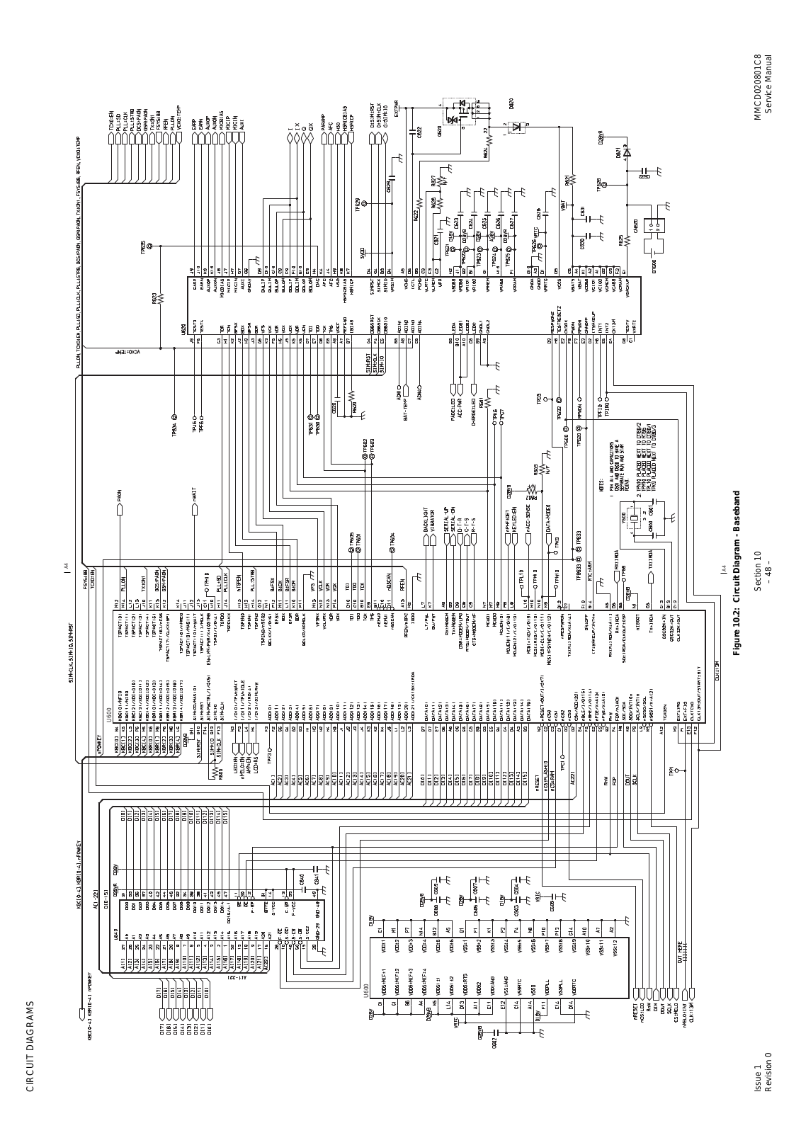
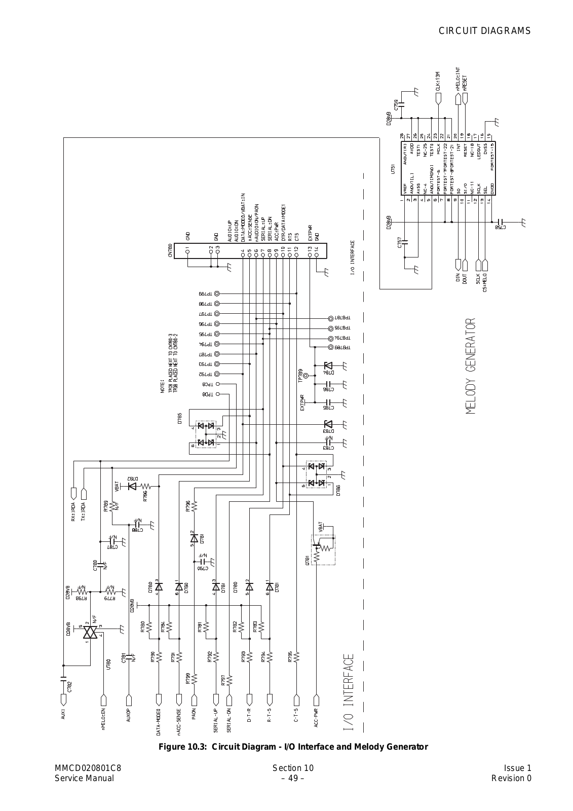
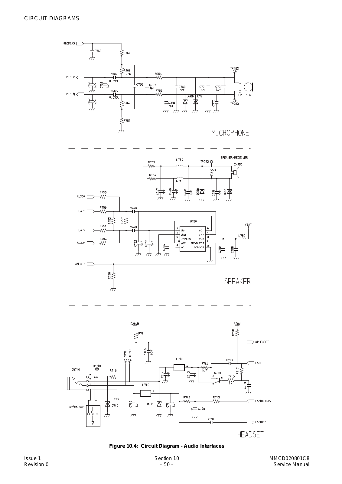
Panasonic EB-GD67 Schematics
...
Panasonic Schematics
Download
Specifications and Main Features
Frequently Asked Questions
User Manual
Download
Page 1
Page 2
Page 3
Page 4
Page 5
Page 6
Page 7
Page 8
Page 9
Page 10
Page 11
Page 12
Loading...
+
hidden pages
Unhide
You need points to download manuals.
1 point = 1 manual.
You can buy points or you can get point for every manual you upload.
Buy points
Upload your manuals
 Loading...