

Panasonic EB-CD400, EB-CR500, EB-HF500Z, EB-G500 Service Manual
Order Number: MCUK960901C8
Service Manual
G500 Personal Cellular Telephone Handheld portable
EB-G500
Car mount kit
EB-HF500Z
Dual charger
EB-CR500
DC Adaptor
EB-CD400
Issue 1
Revision 0

This Service Manual is copyright and issued on the strict understanding that it is not to be reproduced, copied, or
disclosed to any third party, either in whole or part, without the prior written consent of Matsushita Communication
Industrial UK Ltd.
Every care has been taken to ensure that the contents of this manual give an accurate representation of the
equipment. However, Matsushita Communication Industrial UK Ltd. accepts no responsibility for inaccuracies which
may occur and reserves the right to make changes to specification or design without prior notice.
The information contained in this manual and all rights in any designs disclosed therein, are and remain the
exclusive property of Matsushita Communication Industrial UK Ltd.
Other patents applying to material contained in this publication:
BULL CP8 PATENT
INNOVATRON PATENTS
Comments or correspondence concerning this manual should be addressed to:
Customer Support Department,
Matsushita Communication Industrial UK Ltd.,
Colthrop,
Thatcham,
Berkshire. RG19 4ZD.
ENGLAND
© 1996 Matsushita Communication Industrial UK Ltd.
Issue 1 ii MCUK960901C8
Revision 0 Service Manual
TABLE OF CONTENTS
1 INTRODUCTION
1.1 Purpose of this Manual . . . . . . . . . . . . . . . . . . . . . . . . . . . . . . . . . . . . . . . . . . . . . . . . 1-1
1.2 Structure of the Manual . . . . . . . . . . . . . . . . . . . . . . . . . . . . . . . . . . . . . . . . . . . . . . . . 1-1
1.3 Servicing Responsibilities . . . . . . . . . . . . . . . . . . . . . . . . . . . . . . . . . . . . . . . . . . . . . . . 1-1
2 GENERAL DESCRIPTION
2.1General ........................................................2-1
2.2 Handportable Main Kit . . . . . . . . . . . . . . . . . . . . . . . . . . . . . . . . . . . . . . . . . . . . . . . . . 2-1
2.3HandsfreeCarMountKit ...............................................2-2
2.4HolderKit .......................................................2-3
2.5DCAdaptor ......................................................2-3
2.6 Dual Charger and Carry Case . . . . . . . . . . . . . . . . . . . . . . . . . . . . . . . . . . . . . . . . . . . . . 2-4
2.7 Battery Packs . . . . . . . . . . . . . . . . . . . . . . . . . . . . . . . . . . . . . . . . . . . . . . . . . . . . . 2-4
2.8 PCMCIA Interface Card . . . . . . . . . . . . . . . . . . . . . . . . . . . . . . . . . . . . . . . . . . . . . . . . 2-5
2.8 Kit Composition . . . . . . . . . . . . . . . . . . . . . . . . . . . . . . . . . . . . . . . . . . . . . . . . . . . . 2-6
3 OPERATING INSTRUCTIONS
3.1General ........................................................3-1
3.2 LCD Display . . . . . . . . . . . . . . . . . . . . . . . . . . . . . . . . . . . . . . . . . . . . . . . . . . . . . . 3-1
3.3 Location of Controls . . . . . . . . . . . . . . . . . . . . . . . . . . . . . . . . . . . . . . . . . . . . . . . . . . 3-2
3.4 G500 Function Menu Structure . . . . . . . . . . . . . . . . . . . . . . . . . . . . . . . . . . . . . . . . . . . . 3-3
3.5 Basic Operation . . . . . . . . . . . . . . . . . . . . . . . . . . . . . . . . . . . . . . . . . . . . . . . . . . . . 3-4
3.6Troubleshooting....................................................3-5
3.7 Error Messages . . . . . . . . . . . . . . . . . . . . . . . . . . . . . . . . . . . . . . . . . . . . . . . . . . . . 3-5
3.8 Security Codes . . . . . . . . . . . . . . . . . . . . . . . . . . . . . . . . . . . . . . . . . . . . . . . . . . . . . 3-7
3.9 GSM Services Supported by PCMCIA Card . . . . . . . . . . . . . . . . . . . . . . . . . . . . . . . . . . . . . 3-8
3.10 GSM Network Codes and Names . . . . . . . . . . . . . . . . . . . . . . . . . . . . . . . . . . . . . . . . . . 3-9
3.11 Glossary of Terms . . . . . . . . . . . . . . . . . . . . . . . . . . . . . . . . . . . . . . . . . . . . . . . . . 3-12
4 INSTALLATION GUIDE
4.1General ........................................................4-1
4.2HandsfreeCarMountKit ...............................................4-1
4.3DCAdaptor ......................................................4-6
5 DISASSEMBLY/REASSEMBLY INSTRUCTIONS
5.1General ........................................................5-1
5.2 Handportable Unit . . . . . . . . . . . . . . . . . . . . . . . . . . . . . . . . . . . . . . . . . . . . . . . . . . . 5-2
5.3DualCharger......................................................5-8
5.4 Handsfree Unit . . . . . . . . . . . . . . . . . . . . . . . . . . . . . . . . . . . . . . . . . . . . . . . . . . . . 5-10
MCUK960901C8 iii Issue 1
Service Manual Revision 0
6 TECHNICAL SPECIFICATIONS
6.1General.........................................................6-1
6.2HandportableUnit ...................................................6-1
6.3 Handsfree Unit . . . . . . . . . . . . . . . . . . . . . . . . . . . . . . . . . . . . . . . . . . . . . . . . . . . . . 6-5
6.4DualCharger......................................................6-5
6.5 AC Adaptor . . . . . . . . . . . . . . . . . . . . . . . . . . . . . . . . . . . . . . . . . . . . . . . . . . . . . . . 6-6
6.6 DC Adaptor . . . . . . . . . . . . . . . . . . . . . . . . . . . . . . . . . . . . . . . . . . . . . . . . . . . . . . . 6-6
6.7 Battery Pack (S) . . . . . . . . . . . . . . . . . . . . . . . . . . . . . . . . . . . . . . . . . . . . . . . . . . . . 6-7
6.8 Battery Pack (M) . . . . . . . . . . . . . . . . . . . . . . . . . . . . . . . . . . . . . . . . . . . . . . . . . . . . 6-7
6.9 Battery Pack (XL) . . . . . . . . . . . . . . . . . . . . . . . . . . . . . . . . . . . . . . . . . . . . . . . . . . . 6-7
7 TEST AND MEASUREMENT
7.1 Introduction . . . . . . . . . . . . . . . . . . . . . . . . . . . . . . . . . . . . . . . . . . . . . . . . . . . . . . . 7-1
7.2 Test Command Mode . . . . . . . . . . . . . . . . . . . . . . . . . . . . . . . . . . . . . . . . . . . . . . . . . 7-2
7.3ExternalTesting ....................................................7-8
7.4 External Test Commands . . . . . . . . . . . . . . . . . . . . . . . . . . . . . . . . . . . . . . . . . . . . . . 7-16
7.5 Adjustment Mode . . . . . . . . . . . . . . . . . . . . . . . . . . . . . . . . . . . . . . . . . . . . . . . . . . . 7-19
7.6 SIM Personalisation . . . . . . . . . . . . . . . . . . . . . . . . . . . . . . . . . . . . . . . . . . . . . . . . . 7-29
8 CIRCUIT DIAGRAMS
8.1 Handheld Unit . . . . . . . . . . . . . . . . . . . . . . . . . . . . . . . . . . . . . . . . . . . . . . . . . . . . . 8-1
8.2 Handsfree Unit . . . . . . . . . . . . . . . . . . . . . . . . . . . . . . . . . . . . . . . . . . . . . . . . . . . . . 8-3
9 PCB LAYOUT DIAGRAMS
9.1 Handheld Unit . . . . . . . . . . . . . . . . . . . . . . . . . . . . . . . . . . . . . . . . . . . . . . . . . . . . . 9-1
8.2 Handsfree Unit . . . . . . . . . . . . . . . . . . . . . . . . . . . . . . . . . . . . . . . . . . . . . . . . . . . . . 9-3
10 PARTS LIST
10.1HandheldUnit....................................................10-1
10.2 Handsfree Unit . . . . . . . . . . . . . . . . . . . . . . . . . . . . . . . . . . . . . . . . . . . . . . . . . . . 10-2
10.3 Handheld Replacement Parts List . . . . . . . . . . . . . . . . . . . . . . . . . . . . . . . . . . . . . . . . . 10-3
10.4 Handsfree Replacement Parts List . . . . . . . . . . . . . . . . . . . . . . . . . . . . . . . . . . . . . . . . 10-15
10.5DualCharger ................................................... 10-22
10.6 DC Adaptor . . . . . . . . . . . . . . . . . . . . . . . . . . . . . . . . . . . . . . . . . . . . . . . . . . . . 10-22
10.7 PCMCIA Data Interface Card . . . . . . . . . . . . . . . . . . . . . . . . . . . . . . . . . . . . . . . . . . . 10-22
Issue 1 iv MCUK960901C8
Revision 0 Service Manual
WARNINGS AND CAUTIONS
WARNINGS AND CAUTIONS
WARNING
The equipment described in this manual contains polarised capacitors utilising liquid electrolyte. These devices are
entirely safe provided that neither a short-circuit nor a reverse polarity connection is made across the capacitor
terminals. FAILURE TO OBSERVE THIS WARNING COULD RESULT IN DAMAGE TO THE EQUIPMENT OR, AT
WORST, POSSIBLE INJURY TO PERSONNEL RESULTING FROM ELECTRIC SHOCK OR THE AFFECTED
CAPACITOR EXPLODING. EXTREME CARE MUST BE EXERCISED AT ALL TIMES WHEN HANDLING THESE
DEVICES.
Caution
The equipment described in this manual contains electrostatic sensitive devices (ESDs). Damage can occur to
these devices if the appropriate handling procedure is not adhered to.
ESD Handling precautions:
A working area where ESDs may be safely handled without undue risk of damage from electrostatic discharge,
must be available. The area must be equipped as follows:
Working Surfaces - All working surfaces must have a dissipative bench mat, SAFE for use with live equipment,
connected via a 1M2 resistor (usually built into the lead) to a common ground point.
Wrist Strap - A quick release skin contact device with a flexible cord, which has a built in safety resistor of between
5k2 and 1M2 shall be used. The flexible cord must be attached to a dissipative earth point.
Containers - All containers and storage must be of the conductive type.
Batteries
This equipment contains an internal battery in addition to the external battery packs. These batteries are re-cyclable
and should be disposed of in accordance with local legislation. They must not be incinerated, or disposed of as
ordinary rubbish.
MCUK960901C8 v Issue 1
Service Manual Revision 0

WARNINGS AND CAUTIONS
This page is intentionally blank
Issue 1 vi MCUK960901C8
Revision 0 Service Manual
INTRODUCTION
1 INTRODUCTION
1.1 Purpose of this Manual
This Service Manual contains the information and procedures required for installing, operating and servicing the
Panasonic GSM Personal Cellular Mobile Telephone system operating on the GSM Digital Cellular Network.
1.2 Structure of the Manual
The manual is structured to provide service engineering personnel with the following information and procedures:
1. General and technical information - provides a basic understanding of the equipment, kits and options, together
with detailed information for each of the major component parts.
2. Installation and operating information - provides instructions for unpacking, installing and operating the equipment.
3. Servicing information - provides complete instructions for the testing, disassembly, repair and reassembly of each
major component part. Step-by-step troubleshooting information is given to enable the isolation and
identification of a malfunction, and thus determine what corrective action should be taken. The test information
enables verification of the integrity of the equipment after any remedial action has been carried out.
4. Illustrated parts list - provided to enable the identification of all equipment components, for the ordering of
spare/replacement parts.
1.3 Servicing Responsibilities
The procedures described in this manual must be performed by qualified service engineering personnel, at an
authorised service centre.
The service engineering personnel are responsible for fault diagnosis and repair of all equipment described in this
manual.
MCUK960901C8 Section 1 Issue 1
Service Manual 1- 1 Revision 1

INTRODUCTION
This page is intentionally blank
Issue 1 Section 1 MCUK960901C8
Revision 1 1- 2 Service Manual
GENERAL DESCRIPTION
2 GENERAL DESCRIPTION
2.1 General
This section provides a general description and kit composition details for the GSM Handportable Telephone
system and optional kits.
The GSM handportable may be configured as:
1. Handportable unit.
2. Vehicle-powered (DC adaptor) handportable unit.
3. Handsfree vehicle-mounted unit.
4. PC fax: send and receive (via PCMCIA Interface card).
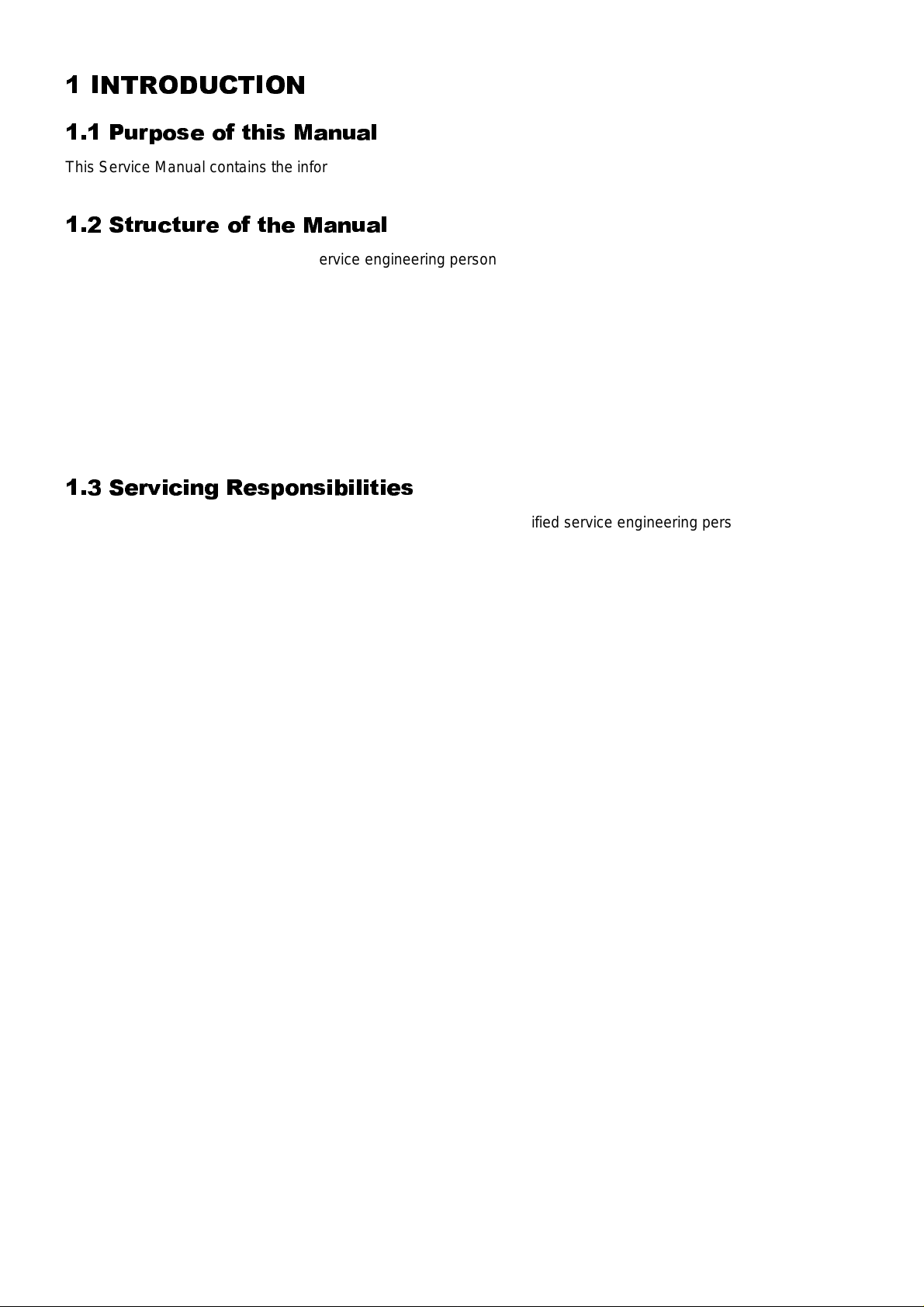
2.2 Handportable Main Kit
The handportable main kit provides a standalone class 4 GSM telephone. The plug-in SIM contains the subscriber
and network information necessary to operate the phone on a GSM network.
2
1
Figure 1:
Handportable Main Unit Kit 500-0201
IDENTIFICATION NUMBER DESCRIPTION PART NUMBER
1 Main unit EB-G500
3
2 Battery EB-BM500
3 Adaptor EB-CA400 UK/EU/SA/TH
— Operating instructions ZD71348A
MCUK960901C8 Section 2 Issue 1
Service Manual 2 - 1 Revision 0
GENERAL DESCRIPTION
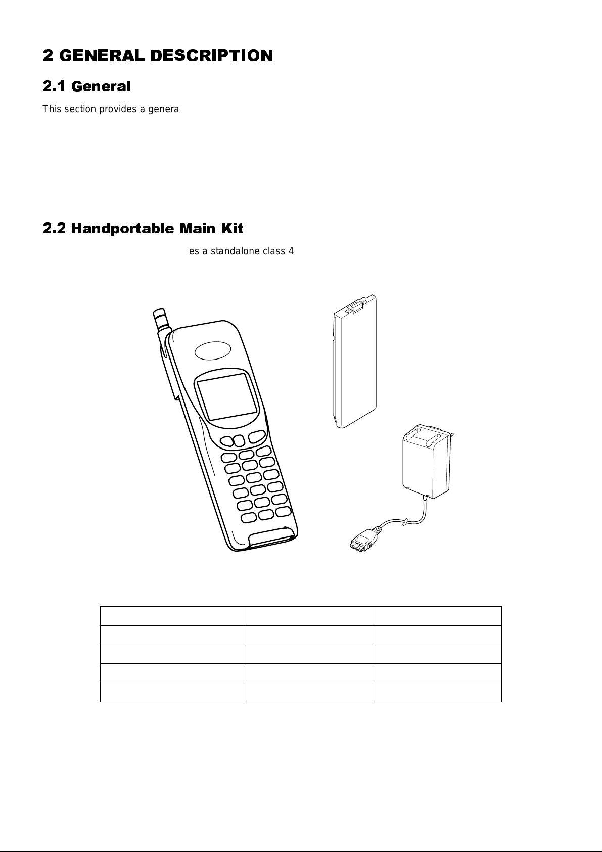
2.3 Handsfree Car Mount Kit
The handsfree car mount kit enables the handportable to be mounted in a vehicle, and to operate in handsfree
mode.
The handsfree unit contains a speaker, with separate volume control. Speech is via a microphone mounted on the
dashboard or the sun visor.
The handsfree unit also provides external power for the handheld internal charger.
Figure 2:
2
4
6
1
3
5
7
Handsfree Car Mount Kit 500-0202
IDENTIFICATION NUMBER DESCRIPTION PART NUMBER
1 Handsfree unit EB-HF400
2 Holder – G350/G400 EB-KA400
3 Holder – G500 EB-KA500
4 Handsfree microphone EBM1177
5 Adjustable angle bracket EBN0001
6 Adjustable angle bracket EBN0002
7 Power supply cable EBW70090
Issue 1 Section 2 MCUK960901C8
Revision 0 2 - 2 Service Manual
GENERAL DESCRIPTION
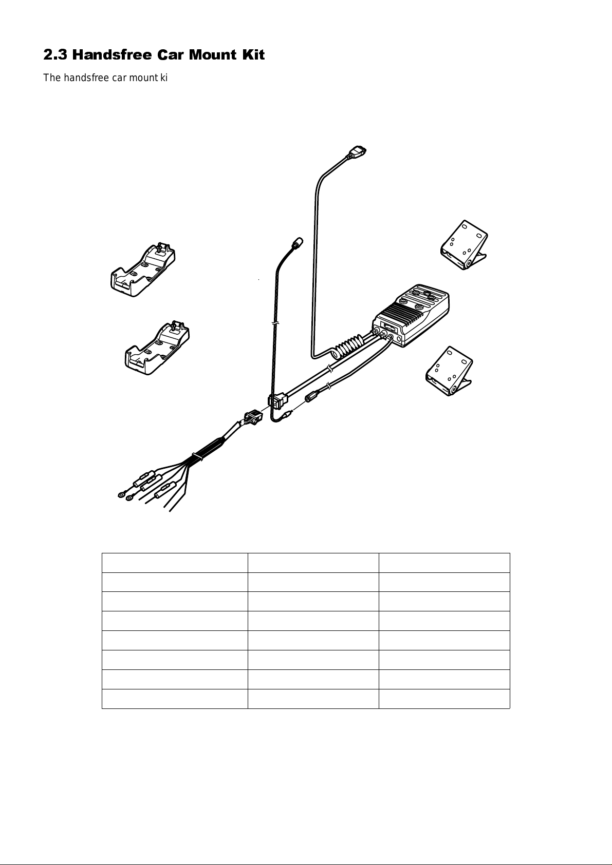
2.4 Holder Kit
The holder kit allows convenient mounting of the telephone in a vehicle. In conjunction with the DC adaptor this can
make a simple car mount kit. The adjustable angle bracket and telephone holder are attached to a convenient fixing
point in the vehicle.
1
2
Figure 3:
Holder Kit 500-0204
IDENTIFICATION NUMBER DESCRIPTION PART NUMBER
1 Holder EB-KA500
2 Adjustable angle bracket EBN0002
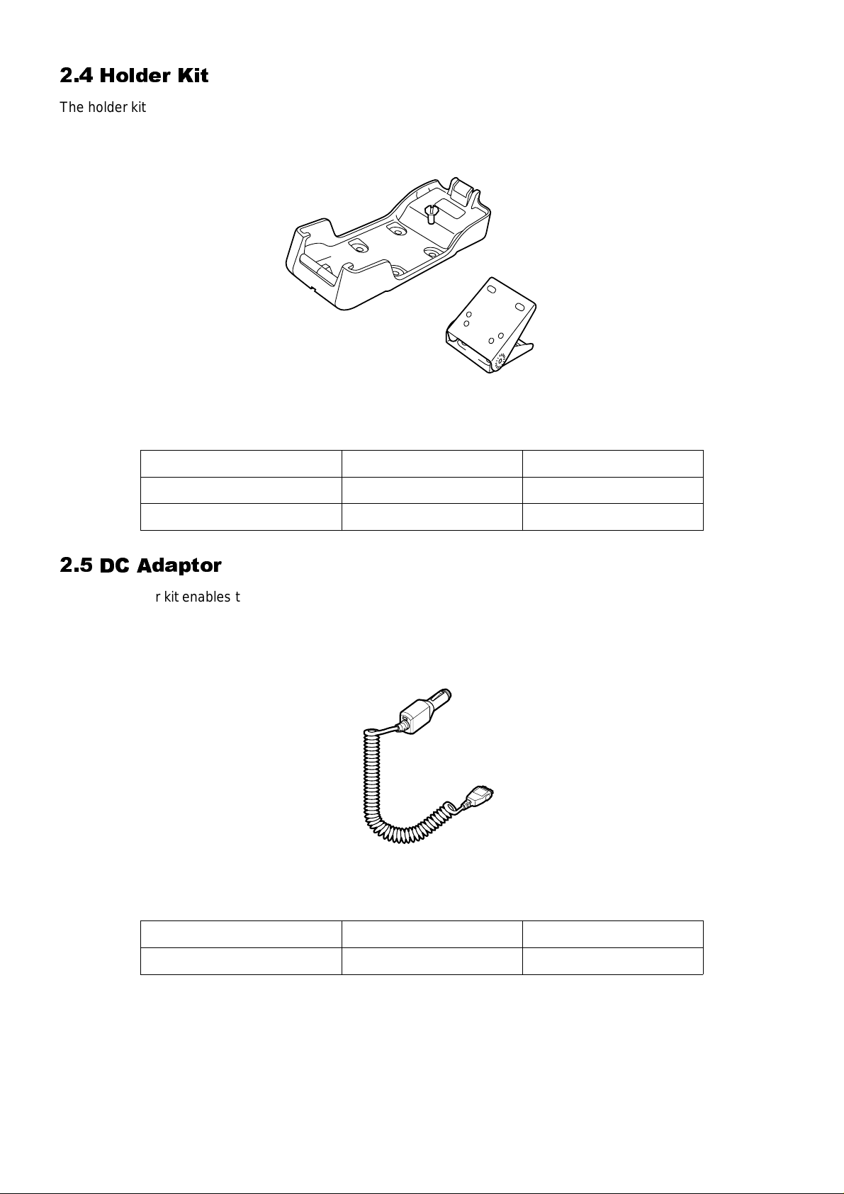
2.5 DC Adaptor
The DC adaptor kit enables the handportable unit to be powered from a vehicle battery, provided that the vehicle
has a cigar lighter socket.
One end of the DC adaptor plugs into the handportable with the telephone battery connected. The other end of the
adaptor is pushed into the cigar lighter socket.
1
Figure 4:
MCUK960901C8 Section 2 Issue 1
Service Manual 2 - 3 Revision 0
DC Adaptor 500-0203
IDENTIFICATION NUMBER DESCRIPTION PART NUMBER
1 DC Adaptor unit EB-CD400A
GENERAL DESCRIPTION
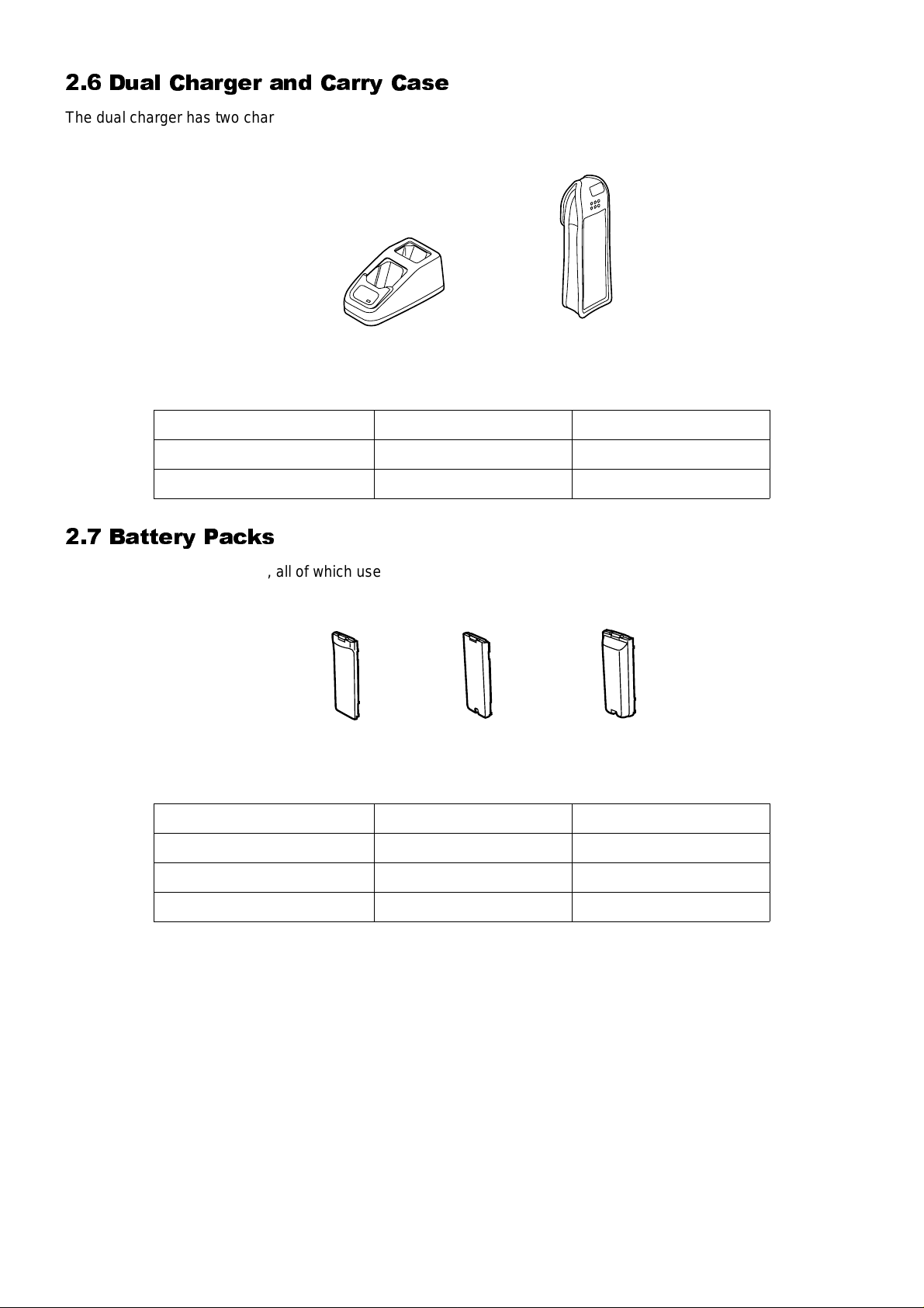
2.6 Dual Charger and Carry Case
The dual charger has two charging slots, enabling the telephone battery to be charged individually or as a part of
the whole telephone assembly.
2
1
Figure 5:
Dual Charger and Carry Case 500-0205
IDENTIFICATION NUMBER DESCRIPTION PART NUMBER
1 Dual charger EB-CR500
2 Carry case EB-YK400
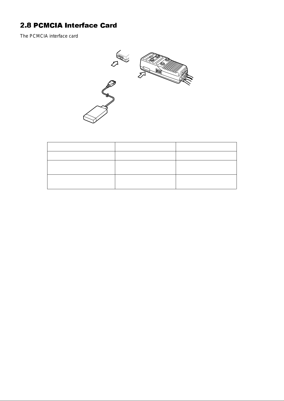
2.7 Battery Packs
There are three battery packs, all of which use Ni-MH. The Battery Pack (S) is 600mAh; the Battery Pack (M) is
850mAh and the Battery Pack (XL) is 1600mAh.
Figure 6:
1
Battery Packs 500-0206
2
3
IDENTIFICATION NUMBER DESCRIPTION PART NUMBER
1 Battery Pack (S) EB-BS500
2 Battery Pack (M) EB-BM500
3 Battery Pack (XL) EB-BX500
Issue 1 Section 2 MCUK960901C8
Revision 0 2 - 4 Service Manual
GENERAL DESCRIPTION
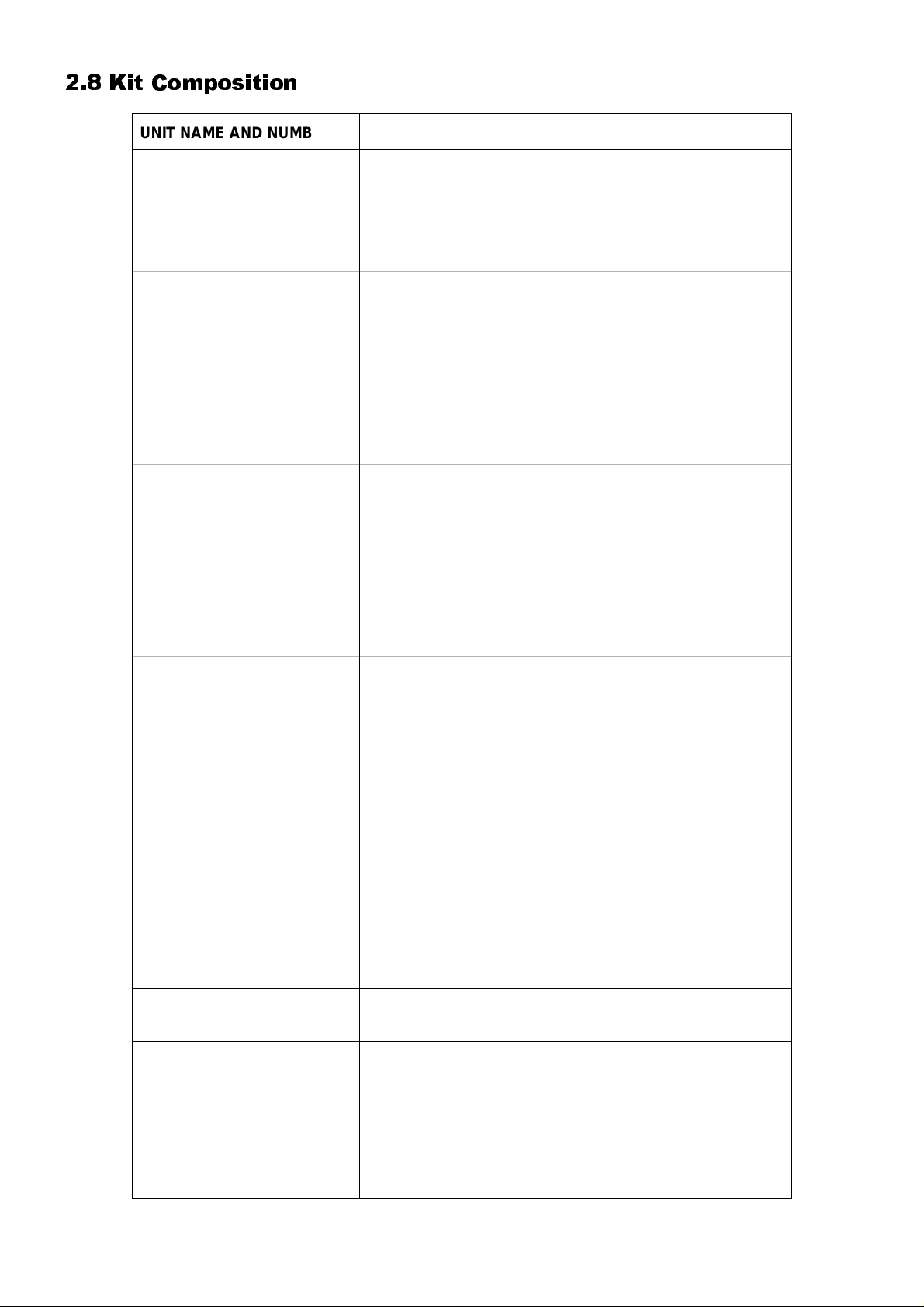
2.8 PCMCIA Interface Card
The PCMCIA interface card is used with the handportable and a laptop personal computer to provide a PC fax and
modem facility.
3
2
1
Figure 7:
PCMCIA Card 500-0207
IDENTIFICATION NUMBER DESCRIPTION PART NUMBER
1 PCMCIA Interface card EB-PA400
2
3
Handsfree unit
– connection
Telephone
– connection
—
—
MCUK960901C8 Section 2 Issue 1
Service Manual 2 - 5 Revision 0
GENERAL DESCRIPTION
2.8 Kit Composition
UNIT NAME AND NUMBER KIT CONTENTS
Main Unit Kit
Operating Instructions
EB-G500 Main Unit
EB-BM500 Battery Pack (M)
EB-CA400 AC Adaptor (‘EU’, ‘SA’, ‘TH’ or ‘UK’)
ZD70052C GSM Network Codes and Names
and at least one operating instruction, quick reference and
quick start from below.
Arabic ZD71411A Chinese ZD71412A
Czech ZD71496A Danish ZD71349A
Dutch ZD71350A English ZD71348A
Finnish ZD71351A French ZD71352A
German ZD71353A Greek ZD71354A
Hungarian ZD71497A Italian ZD71355A
Norwegian ZD71356A Polish ZD71498A
Portuguese ZD71357A Russian ZD71495A
Spanish ZD71358A Swedish ZD71359A
Turkish ZD71360A
Quick Reference
Quick Start
Car Mount Kit
EB-HF400Z
Arabic ZD71413A Chinese ZD71414A
Czech ZD71500A Danish ZD71362A
Dutch ZD71363A English ZD71361A
Finnish ZD71364A French ZD71365A
German ZD71366A Greek ZD71367A
Hungarian ZD71501A Italian ZD71368A
Norwegian ZD71369A Polish ZD71502A
Portuguese ZD71370A Russian ZD71499A
Spanish ZD71371A Swedish ZD71372A
Turkish ZD71373A
Arabic ZD71428A Chinese ZD71429A
Czech ZD71504A Danish ZD71416A
Dutch ZD71417A English ZD71415A
Finnish ZD71419A French ZD71418A
German ZD71420A Greek ZD71421A
Hungarian ZD71505A Italian ZD71422A
Norwegian ZD71423A Polish ZD71506A
Portuguese ZD71424A Russian ZD71503A
Spanish ZD71425A Swedish ZD71426A
Turkish ZD71427A
EB-HF400 H/F Unit
EB-KA400 Holder – G350/G400
EB-KA500 Holder – G500
EBM1177 Microphone
EBN0001 AA Bracket
EBN0002 AA Bracket 2
EBW70090 Power Supply Cable
Holder Kit
EB-KA500Z
Other Optional Accessories
Issue 1 Section 2 MCUK960901C8
Revision 0 2 - 6 Service Manual
EB-KA500 Holder
EBN0002 AA Bracket 2
EB-CD400A DC Adaptor
EB-CR500 Dual Charger
EB-YK400 Carry Case
EB-BS500 Battery Pack (S)
EB-BM500 Battery Pack (M)
EB-BX500 Battery Pack (XL)
EB-PA400 PCMCIA Data Interface Card
EB-CA400 AC Adaptor
OPERATING INSTRUCTIONS
3 OPERATING INSTRUCTIONS
3.1 General
This section provides a brief guide to the operation and facilities available on the G500 handportable unit. Refer to
the Operating Instructions for full operational information.
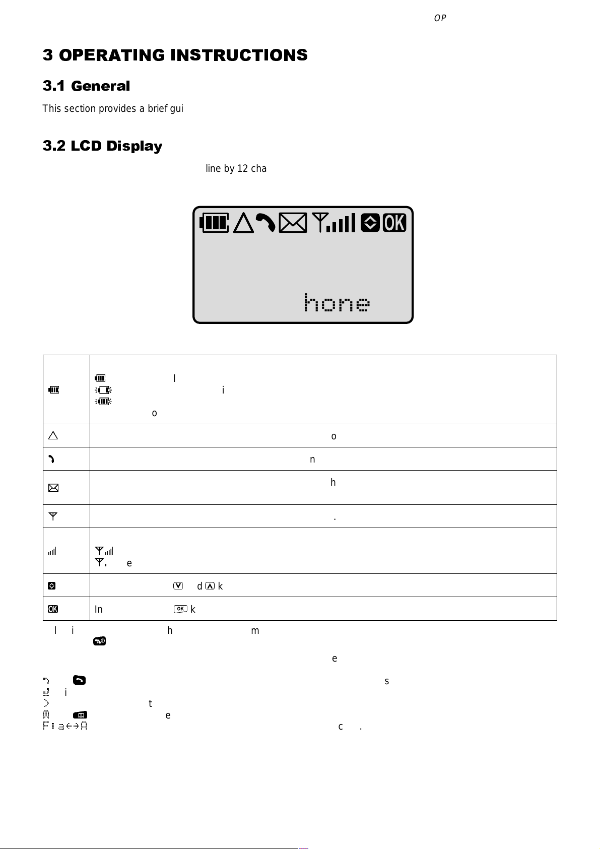
3.2 LCD Display
The G500 handportable unit has a 3 line by 12 character chip on glass liquid crystal display in conjunction with the
following icons:
Panasonic
G500
GSM Phone
Figure 1:
H
T
N
W
A
R
v
o
Following some operations the display will automatically clear after three seconds or after pressing any
key except
The display will also show other symbols that will indicate which key can be pressed next or the current setting of a
function:
`
TheSkey can be pressed or this is the active call when there are two calls.
»
This is the held call when there are two calls.
>
This is the current setting for the chosen function.
¼
ThePkey can be pressed.
F:a{}A
LCD display 500-0301
Displays the battery charge level:
H
Battery is at full charge.
K
Battery requires recharging.
G
The battery icon flashes during charging.
During car mount use, when the battery is fully charged, the battery icon will not light.
Indicates that you are registered on a non-home network.
Indicates that a call is in progress or flashes when a call is on hold.
Indicates the reception of a short text message from the Short Message Service (SMS).
This icon will flash when a message has not been read.
Indicates that it is possible to make an emergency call.
Indicates received signal strength:
AR
Strong signal area.
AY
Weak signal area.
Indicates that theVandUkeys can be pressed.
Indicates that theOkey can be pressed.
E
.
Pressing the F key will toggle between upper and lower case.
MCUK960901C8 Section 3 Issue 1
Service Manual 3 - 1 Revision 0
OPERATING INSTRUCTIONS
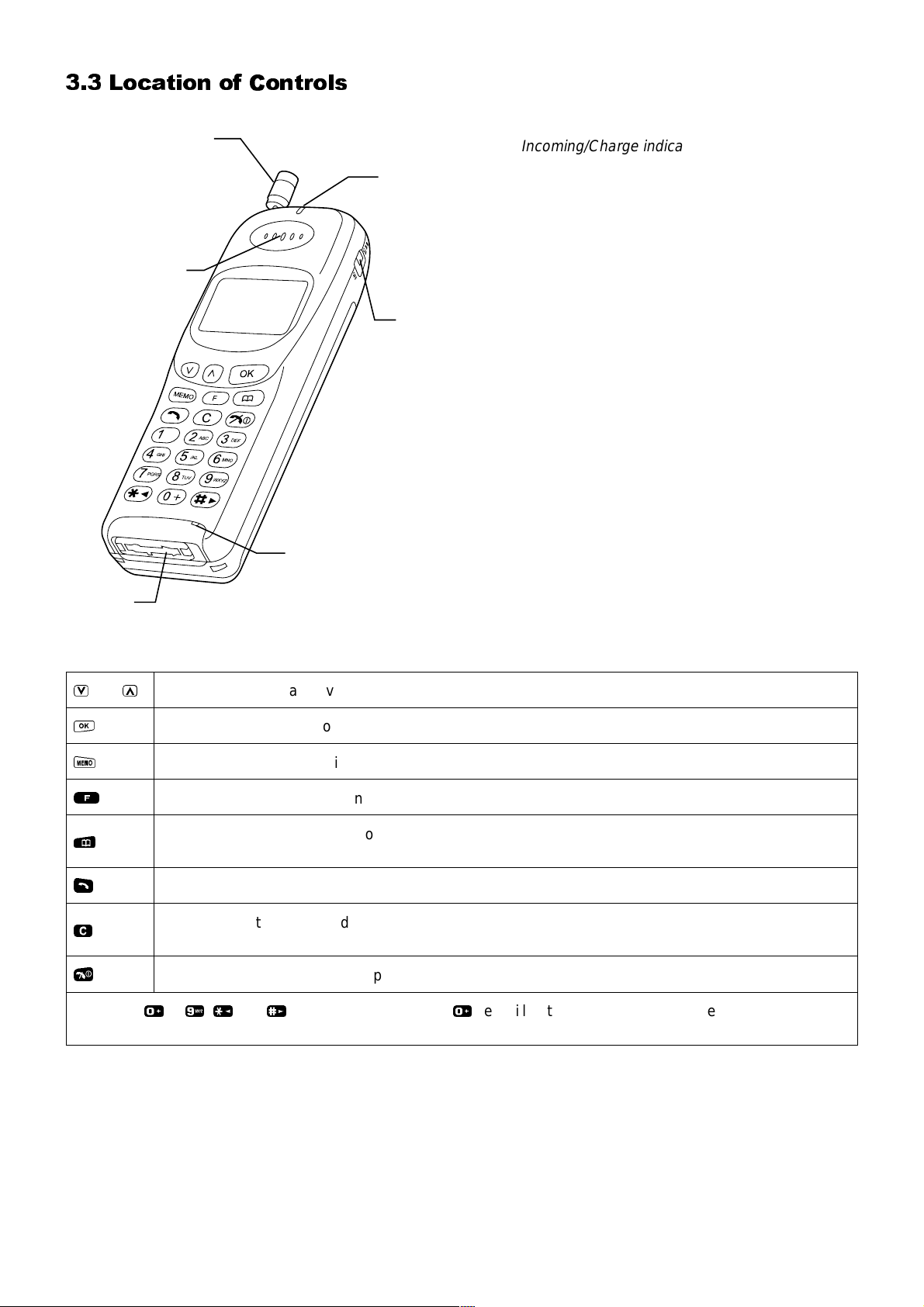
3.3 Location of Controls
Extrenal
connector
Antenna
Earpiece
Figure 2:
Incomming/Charge
indicator
Incoming/Charge indicator:
Green – incoming call.
Red – charging battery pack.
Display
Vibration alert
switch
Vibration alert switch:
ON – telephone will vibrate with an incoming call.
OFF – telephone will ring with an incoming call.
Microphone
External connector:
Used to connect to external accessories or
charging equipment.
Location of controls for G500 500-0302
V
and
O
M
F
P
S
C
E
Digit keys
Increases or decreases volume, scrolls through options or function menu.
U
Enters data, selects an option or confirms an action.
Records or plays back voice memo.
Enters function menu or changes between upper and lower case letters.
Recalls memory, accesses short messages, displays the rest of a telephone number or name tag
when pressed and held.
Makes a call.
Clears the last digit entered, clears all digits when pressed and held or returns to the previous
display.
Ends a call or switches the telephone on/off when pressed and held.
0to9,*
and#. Where appropriate the0key will enter the international access code “+”, wild
numbers or pauses when pressed and held.
Issue 1 Section 3 MCUK960901C8
Revision 0 3 - 2 Service Manual
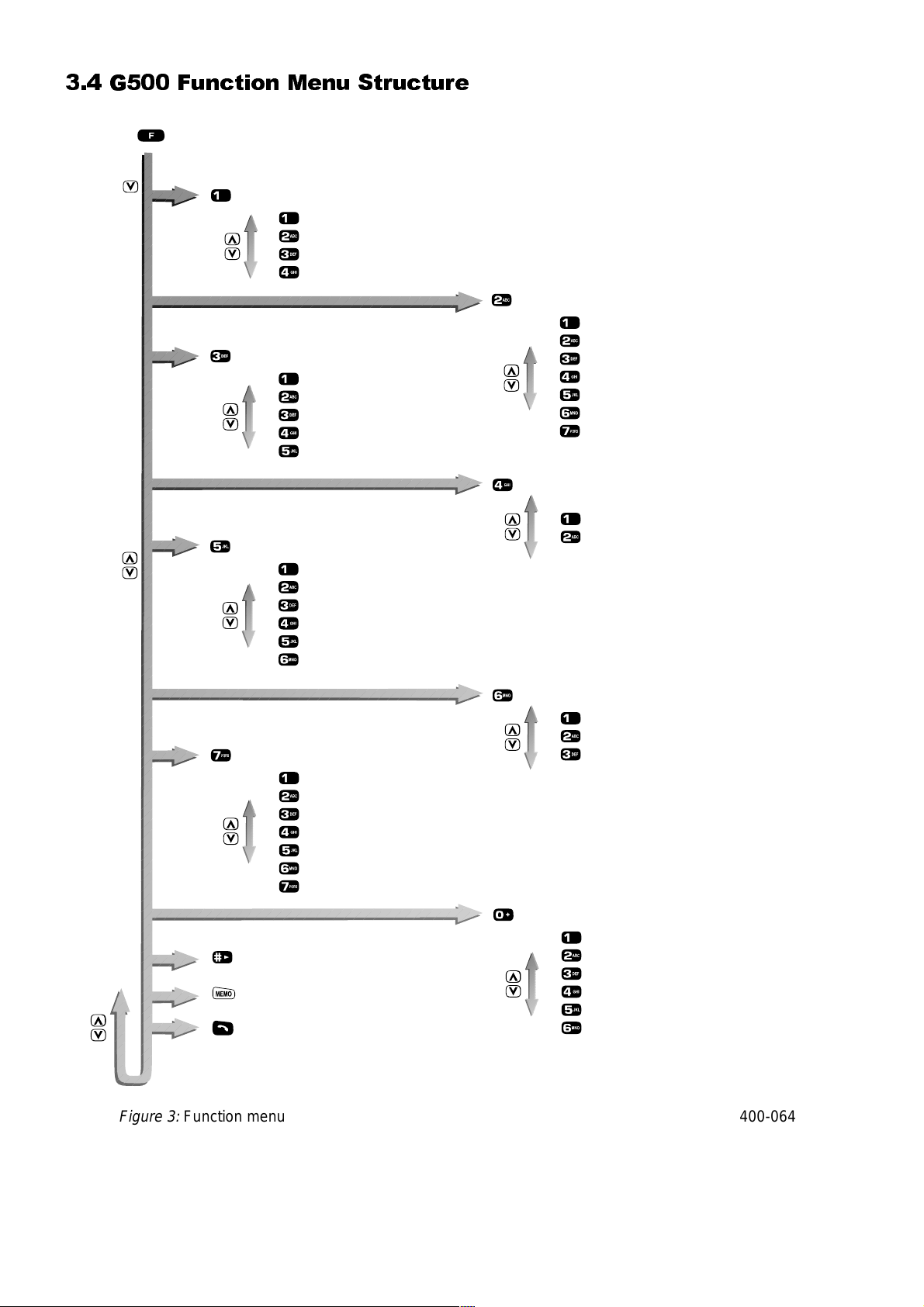
3.4 G500 Function Menu Structure
Call meter
Last call meter
Accumulated call meter
Price per unit
Call limit
Divert
All calls
If busy
No answer
Unreachable
Status
OPERATING INSTRUCTIONS
Call bar
All outgoing
Outgoing international
Outgoing international except home
All incoming
Incoming while roaming
Status
New password
Messages
Read a message
Delete a message
Automatically clear messages
Send/edit a message
Message centre
Cell broadcast
Customise
Language
Ring volume
Ring type
DTMF tone type
Automatic redial
Automatic answer
Ignition off timer
Hold call
Delete voice memo
Send DTMF
Call waiting
Set call waiting
Status
Networks
Manual network selection
Preferred network list
My telephone number
Security
Lock level
New lock code
PIN on/off
New PIN
New PIN2
Fixed dial
Figure 3:
MCUK960901C8 Section 3 Issue 1
Service Manual 3 - 3 Revision 0
Function menu 400-0640
OPERATING INSTRUCTIONS
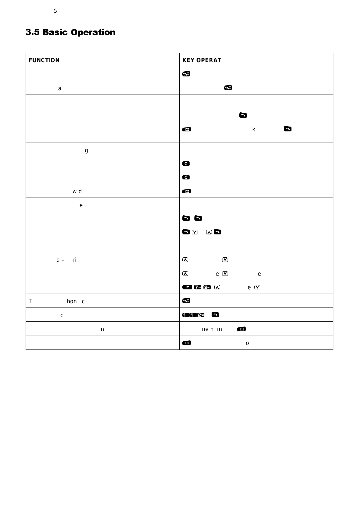
3.5 Basic Operation
FUNCTION KEY OPERATION
To switch ON/OFF
To receive a telephone call
To make a telephone call:
Manually
From memory
To clear misdialled digit(s):
Last digit
All digits
To check overflow digits
To redial last number:
Last dialled number
Other number in last dialled number list
To adjust volume:
E
and hold
Any key except
Telephone number +
followed by phone book number +
P
C
and hold
C
P
and hold
SS
SV
or
US
E
S
S
Key volume – during standby
Ear volume – during a call
Ring volume
To end a telephone call
Emergency calls
Store a telephone number in memory
Recall a number from memory
U
to increase,Vto decrease
U
to increase,Vto decrease
F72,U
E
112+S
telephone number +
P
– the display must not show any numbers
to increase,Vto decrease
P
Issue 1 Section 3 MCUK960901C8
Revision 0 3 - 4 Service Manual
OPERATING INSTRUCTIONS
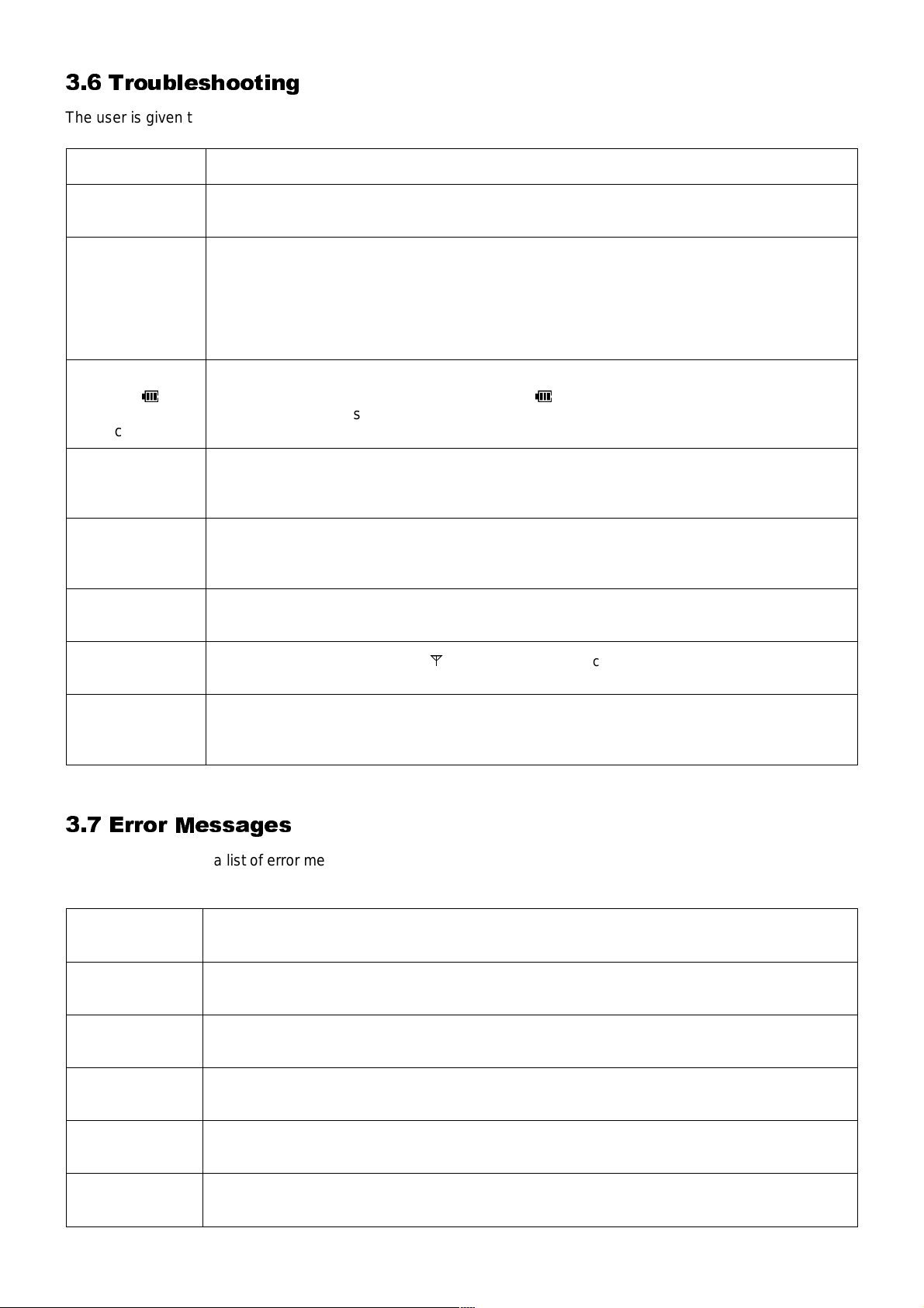
3.6 Troubleshooting
The user is given the following information and advised to contact the dealer if the problems persist:
Problem Causes and Solutions
Telephone will
not switch on
Short battery life
Battery level
indicator (
does not light
when charging
Calls cannot be
made
Calls cannot be
made from Fixed
Dial Memory
Calls cannot be
received
H
)
Check that the battery pack is fully charged and correctly connected to the telephone.
Battery life is affected by the network you are using and the condition of the battery pack.
The life of the battery pack is affected by improper charging, this is inherent in all Ni-MH and
Ni-Cd batteries. To maintain maximum performance always use until the low battery warning
and then fully recharge the battery pack. To revive the battery pack use the telephone until it
switches off and then fully recharge three times. However, the battery pack will eventually
wear out and must be replaced with a new one.
If a battery is deeply discharged it will take a short time before there is sufficient power in the
telephone to display the battery level indicator (
The battery pack must be charged in a temperature no lower than +5°C and no higher than
+35°C.
Calls cannot be made when the telephone is locked or outgoing calls are barred.
Check that the telephone is registered to a network. Move to a coverage area and operate
your telephone after it has registered with a network.
Check the telephone number is stored in Fixed Dial Memory or your SIM supports Fixed Dial
Memory.
To receive a call the telephone must be switched on.
Calls cannot be received when incoming calls are barred.
H
).
Emergency calls
cannot be made
Telephone
numbers cannot
be recalled
Check that the antenna symbol
telephone when the antenna symbol is displayed.
Memory cannot be recalled when the telephone is fully locked or “Fixed Dial” is switched on.
A
is displayed. Move to a coverage area and operate your
3.7 Error Messages
The following table is a list of error messages that may occur during use of the telephone, with a description and
suggested course of action:
AREA NOT
ALLOWED
BLACKLIST
FULL
INVALID SIM
LOCK CODE
INVALID
Roaming in the selected area is not allowed.
Blacklist of unsuccessfully dialled numbers is full. Switch the telephone off and then on
again. Telephone numbers are removed from the blacklist after twenty-four hours.
Your SIM cannot be used in the telephone. The telephone may be personalised to a
particular SIM or network. Contact your service provider.
A wrong lock code has been entered. Re-enter the correct lock code.
LOW BATTERY
MESSAGE
REJECTED
MCUK960901C8 Section 3 Issue 1
Service Manual 3 - 5 Revision 0
The battery power is low. Replace with a fully recharged battery pack or recharge the battery
pack.
A message has been received but the message area is full. To receive messages delete
some of the currently stored messages or set messages to automatically clear.

OPERATING INSTRUCTIONS
NETWORK
ERROR
NETWORK NOT
ALLOWED
NETWORK
REJECTED
NO SIM
PRESENT
The message sent has failed because of a network error. Check that the Message Centre
number is correct or wait for a short while and retry.
Roaming with the selected network is not allowed.
The supplementary service requested has been rejected by the network because of a system
failure. Wait for a short while and retry.
The telephone has not detected a SIM. If a SIM is present remove and then replace it and
make sure that the SIM holder is locked shut.
NOT ALLOWED The entered security code is too short. Enter an appropriate security code.
TEL. NUMBER
TOO LONG
MAX = 20
PASSWORD
INVALID
PIN BLOCKED/
PIN2 BLOCKED
PIN INVALID/
PIN2 INVALID
The memory capacity for storing overflow digits in your SIM is full. You cannot enter more
than twenty digits until some of the overflow telephone numbers stored in memory are
deleted.
A wrong password has been entered. Enter the correct password.
The PIN/PIN2 is blocked because the wrong number has been entered three times. The
telephone will ask you to enter the PUK/PUK2 then you will have to enter a new PIN/PIN2.
The PUK/PUK2 is supplied by your service provider.
A wrong PIN/PIN2 has been entered. Enter the correct PIN/PIN2.
PIN2
INVALIDATED
The PIN2 is blocked permanently because the wrong PUK2 has been entered ten times.
Supplementary services controlled by PIN2 cannot be used. Contact your service provider.
PLEASE RETRY The supplementary service requested has failed. Wait for a short while and retry.
PUK INVALID/
PUK2 INVALID
SECURITY
FAILURE
SIM BLOCKED
SIM ERROR
A wrong PUK/PUK2 has been entered. Enter the correct PUK/PUK2.
The network has detected authentication failure because your SIM is not registered with that
network. Contact your service provider.
The SIM is blocked because the wrong PUK has been entered ten times. Contact your
service provider.
The telephone has detected a problem with the SIM. Switch the telephone off and then back
on. If the message does not disappear contact your service provider.
STORE FULL Phone Book/Fixed Dial Memory is full. Delete an entry or overwrite old information.
SUBSCRIPTION
REVOKED
VACANT
XX XXXXX X
XXXX
The supplementary service requested has been revoked because the wrong password has
been entered four times. Contact your service provider.
There is no information in the memory location that you selected. To clear this display press
C
.
There is a permanent error in the telephone. Switch the telephone off and then back on. If
the message re-appears, contact your dealer.
Issue 1 Section 3 MCUK960901C8
Revision 0 3 - 6 Service Manual
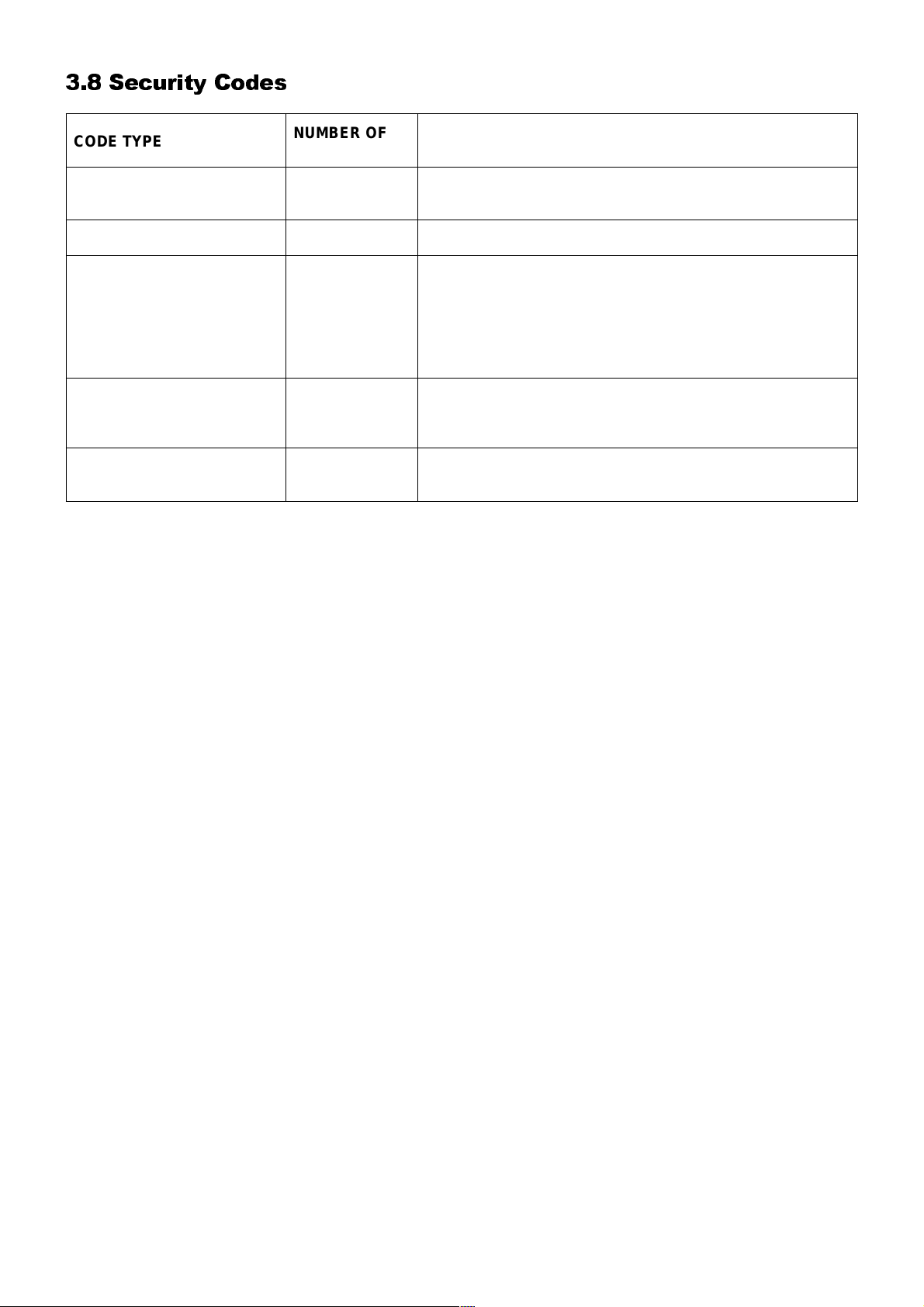
3.8 Security Codes
OPERATING INSTRUCTIONS
CODE TYPE
Personal Identification
Number (PIN)
PIN 2 4 to 8 Controls memory security. Supplied by the service provider.
PIN/PIN 2 Unblocking Key
(PUK/PUK 2)
Password 4
Lock Code 4
NUMBER OF
DIGITS
4 to 8 Controls SIM security. Supplied by the service provider.
8
DESCRIPTION
Used to unblock PIN and PIN 2. A PIN or PIN 2 will become
blocked if the wrong PIN or PIN 2 is entered three times.
When the blocked PIN or PIN 2 is unblocked, a new PIN or
PIN 2 must be entered. If the wrong PUK or PUK 2 is entered
10 times, your SIM will be unusable.
Supplied by the service provider.
Controls the call bar function. If the wrong password is
entered three times, this service will be revoked. Supplied by
the service provider.
Controls telephone security.
Factory set to “0000”.
MCUK960901C8 Section 3 Issue 1
Service Manual 3 - 7 Revision 0
OPERATING INSTRUCTIONS
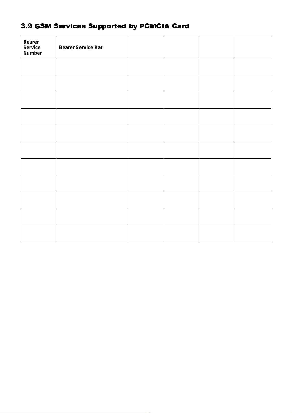
3.9 GSM Services Supported by PCMCIA Card
Bearer
Service
Number
21 Asynchronous 300 bps Asynch 300 bps
22 Asynchronous 1.2 kbps Asynch 1.2 kbps
23 Asynchronous 1200/75 bps Asynch 1200/75 bps
24 Asynchronous 2.4 kbps Asynch 2.4 kbps
25 Asynchronous 4.8 kbps Asynch 4.8 kbps
26 Asynchronous 9.6 kbps Asynch 9.6 kbps
41
42
Bearer Service Rate
Dedicated PAD Access 300
bps
Dedicated PAD Access 1.2
kbps
Access
Structure
Asynch 300 bps UDI T or NT
Asynch 1.2 kbps UDI T or NT
Access Rate
Information
Transfer
UDI or
modem
UDI or
modem
UDI or
modem
UDI or
modem
UDI or
modem
UDI or
modem
Error
Correction
Options
T or NT
T or NT
T or NT
T or NT
T or NT
T or NT
44
45
46
UDI = Unrestricted Digital Information
T = Transparent (non-error corrected)
NT = Non-Transparent (error corrected)
AT commands to select these services are: +CBST, /N and +CIWF.
Dedicated PAD Access 2.4
kbps
Dedicated PAD Access 4.8
kbps
Dedicated PAD Access 9.6
kbps
Asynch 2.4 kbps UDI T or NT
Asynch 4.8 kbps UDI T or NT
Asynch 9.6 kbps UDI T or NT
Issue 1 Section 3 MCUK960901C8
Revision 0 3 - 8 Service Manual
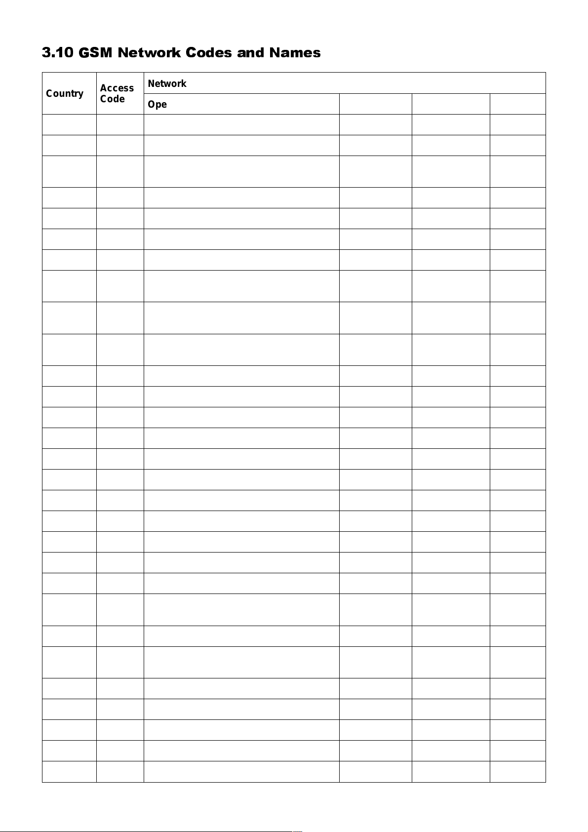
3.10 GSM Network Codes and Names
OPERATING INSTRUCTIONS
Country
AND +37 STA ANDORRA MOBILAND M-AND 213 03
AUS +61 TELECOM Australia MOBILENET M-NET 505 01
AUS +61 OPTUS Communications Pty Ltd.
AUS +61 Vodafone PTY VODAFONE VFONE 505 03
A +43 PTV Austria A1 A1 232 01
BEL +32 Belgacom Mobile PROXIMUS PROXI 206 01
BG +359 MOBILTEL AD CITRON GSM CITRON 284 01
BHR +973 BAHREIN Telecommunications Co.
CH +41 Swiss Telecom PTT
CHN +86
Access
Code
Network
Operator Name Abbreviation Code
China United Telecommuni-cations
Corporation
OPTUS
Mobile
MOBILE
PLUS
NATEL D
GSM
CHINA
UNICOM
OPTUS 505 02
M.PLUS 426 01
NAT D 228 01
CU-GSM 460 01
CY +357 Cyprus Telecommunication Authority CYTAGSM CY-GSM 280 01
D +49 DeTeMobil GmbH Mobilfunk D1 D1 262 01
D +49 Mannesmann Mobilfunk D2 PRIVAT D2 262 02
E +34 TELEFONICA MOVILES MOVISTAR MSTAR 214 07
E +34 AIRTEL SPAIN AIRTEL AIRTL 214 01
EE +372 Eesti Mobiiltelefon EMT GSM EMT 248 01
EE +372 RADIOLINJA EESTI AS EESTI RLE 248 02
DK +45 TELE Danmark Mobile TDK-MOBIL TD MOB 238 01
DK +45 Dansk Mobil Telefon DMT SONOFON SONO 238 02
F +33 France Telecom Itineris Itine 208 01
F +33 SFR SFR SFR 208 10
F +33 SRR
F +33 TIKIPHONE VINI VINI 547 20
FI +358 Telecom Finland
SFR
REUNION
TELECOM
FIN
SFR RU 647 10
TELE 244 91
FI +358 OY Radiolinja AB RADIOLINJA RL 244 05
GIB +350 GIBTEL GIBTEL GIBTEL 266 01
GR +30 Panafon S.A PANAFON PAN 202 05
GR +30 STET HELLAS TELESTET TLSTET 202 10
H +36 Westel 900 GSM RT WESTEL 900 W-900 216 30
MCUK960901C8 Section 3 Issue 1
Service Manual 3 - 9 Revision 0

OPERATING INSTRUCTIONS
Country
Access
Code
H +36 Pannon GSM RT
Network
Operator Name Abbreviation Code
PANNON
GSM
PANNON 216 01
HK +852 Hong Kong Telecom CSL Ltd. TCSL GSM TCSL 454 00
HK +852 Hutchison Telephone Co. Ltd. HTCLGSM HTCL 454 04
HK +852 SmarTone Mobile Communications Ltd. SMARTONE HKSMC 454 06
HR +95 HPT CRONET CRON 219 01
I +39 OMNITEL PRONTO ITALIA OMNITEL OMNI 222 10
I +39 TELECOM ITALIA MOBILE
ITALIA
MOBILE
TIM 222 01
INA +91 Bharti Cellular Limited AirTel AIRTL 404 10
INA +91 BPL SYSTEMS & PROJECTS LTD. INDIA BPL - MOBILE BPL 404 21
IND +62 PT Telekomunikasi Indonesia TELKOMSEL T-SEL 510 10
IND +62 PT. SATELIT PALAPA INDONESIA
SATELINDOCE
L
SAT-C 510 01
IND +62 PT EXCELCOMINDO PRATAMA EXCELCOM EX-CEL 510 11
IRL +353 Telecom Ireland
KSA +966
ELECTRONIC APPLICATIONS
ESTABLISHMENT
KT +96 Mobile Telecommunications Co. MTC
EIRCELL-GSM
EAE-ALJAWW
AL
N
et MTC 419 02
E-GSM 272 01
EAE 420 07
L +352 P & T Luxembourg LUXGSM P&T L 270 01
LV +371 Latvian Mobile Telephone Co.Ltd. LMT GSM LMT 247 01
MAC +853 C.T.M. TELEMOVEL+ CTMGSM 455 01
MOR +212 ONPT MOROCCO ONPT ONPT 604 01
MRU +60 MAURITIUS TELECOM LTD. CELLPLUS CELL + 617 01
MY +60
BINARIANG COMMUNICATIONS SDN
BHD.
maxis mobile maxis 502 12
N +47 Telenor Mobil AS Telenor Mobil Tele N 242 01
N +47 NetCom GSM A/S NetCom GSM N COM 242 02
NL +31 LIBERTEL LIBERTEL LIBTEL 204 04
NL +31 PTT Telecom
PTT
TELECOM
NL PTT 204 08
NZ +64 BELLSOUTH BELLSOUTH BSNZ 530 01
P +351
Telecomunicaçoes Moveis Nacionais
(TMN)
TMN TMN 268 06
P +351 TELECEL TELECEL TLCL 268 01
PH +63 Globe Telecom GMCR Inc
Issue 1 Section 3 MCUK960901C8
Revision 0 3 - 10 Service Manual
Globe
Telecom
GLOBE 515 02

OPERATING INSTRUCTIONS
Network
Operator Name Abbreviation Code
Country
Access
Code
PH +63 Isla Communications Co. Inc. Islacom ISLA 515 01
QAT +974 Q-TEL QATARNET Q-NET 427 01
ROC +886 LDTA LDTA GSM LDGSM 466 92
RL +961 Telecom Finland International LibanCell LibCL 415 03
RUS +701 Mobile Telesystems MTS MTS 250 01
RUS +701 North-West GSM
S +46 Telia Mobitel
North-West
GSM
TELIA
MOBITEL
NWGSM 250 02
TELIA 240 01
S +46 COMVIQ GSM AB COMVIQ IQ 240 07
S +46 EUROPOLITAN AB
EUROPOLITAN
EURO 240 08
SA +27 VODACOM VodaCom VODA 655 01
SA +27 Mobile Telephone Networks MTN MTN 655 10
SGP +65 Singapore Telecom ST-GSM STGSM 525 01
SRI +94 MTN NETWORKS (PVT) SRI LANKA DIALOG DALOG 413 02
SYR +963 Mobile Syria
TH +66
Advanced Info Service Public Company
Limited
TR +90 PTT Turkey
TR +90 PTT Turkey
MOBILE
SYRIA
SYR MOB 417 09
AIS GSM TH AIS 520 01
TURKCELL
GSM
PTT TELSIM
GSM
TCELL 286 01
TLSIM 286 02
UAE +971 ETISALAT ETISALAT ETSLT 424 02
UK +44 Cellnet CELLNET CLNET 234 10
UK +44 GUERNSEY TELECOMS
GUERNSEY
TEL
GSY-TEL 234 55
UK +44 Jersey Telecoms Jersey Tele JER1 234 50
UK +44 MANX TELECOM
PRONTO
GSM
MANX 234 58
UK +44 Vodafone VODAFONE VODA 234 15
MCUK960901C8 Section 3 Issue 1
Service Manual 3 - 11 Revision 0

OPERATING INSTRUCTIONS
3.11 Glossary of Terms
Dual Tone Multiple Frequency tones. The numeric keys 0 to 9, and ∗ and # will generate
DTMF
different DTMF tones when pressed during conversation. These are used to access voice
mail, paging and computerised home banking.
GSM
Home country The country where your home network operates.
Home network The GSM network on which your subscription details are held.
Lock code Used for security of your telephone. Factory set to “0000”.
Message Centre
Network
operator
Password Used for the control of the call bar function. Supplied by your service provider.
PIN Personal Identification Number used for SIM security. Supplied by your service provider.
PIN2
PUK/ PUK2 PIN/PIN2 Unblocking Key. Used to unblock the PIN/PIN2. Supplied by your service provider.
Registration
Global System for Mobile communications. The name given to the advanced digital
technology that your telephone uses.
Where messages are sent before they are forwarded onto their destination. The Message
Centre telephone number may be programmed into your SIM or supplied by your service
provider.
The organisation responsible for operating a GSM network. Each country will have at least
one network operator.
Personal Identification Number used for the control of Fixed Dial Memory and call charge
metering. Supplied by your service provider.
The act of locking on to a GSM network. This is usually performed automatically by your
telephone.
Roaming The ability to use your telephone on networks other than your Home network.
Service provider The organisation responsible for providing access to the GSM network.
Subscriber Identification Module. A small smart-card which stores unique subscriber and
SIM
Supplementary
service
Wild numbers
user-entered information such as Phone Book, Fixed Dial Memory and short messages.
Supplied by your service provider.
Network-controlled GSM functions which your telephone will support. Supplementary services
may only be available on a subscription bases.
Spaces in a stored telephone number. When the telephone number is recalled pressing a
numeric key will fill in a space. This can be used to restrict dialling to a specific area.
Issue 1 Section 3 MCUK960901C8
Revision 0 3 - 12 Service Manual
INSTALLATION GUIDE
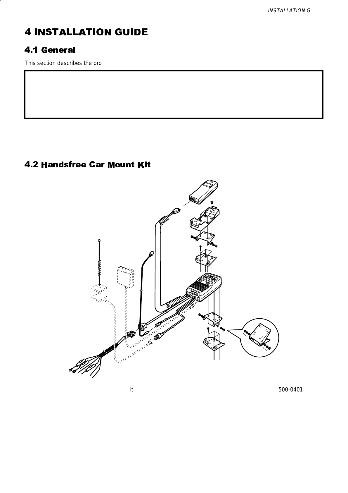
4 INSTALLATION GUIDE
4.1 General
This section describes the procedure used to install the GSM handportable unit into a negative-grounded vehicle.
Caution:
Do not attempt to install this equipment into a positive-grounded vehicle.
Do not attempt to supply power to the equipment from a positive-grounded vehicle.
Installation will be performed using either of the following kits:
1. Handsfree car mount kit
2. DC adaptor.
4.2 Handsfree Car Mount Kit
Figure 1:
MCUK960901C8 Section 4 Issue 1
Service Manual 4 - 1 Revision 0
Handsfree Car Mount Kit 500-0401
INSTALLATION GUIDE
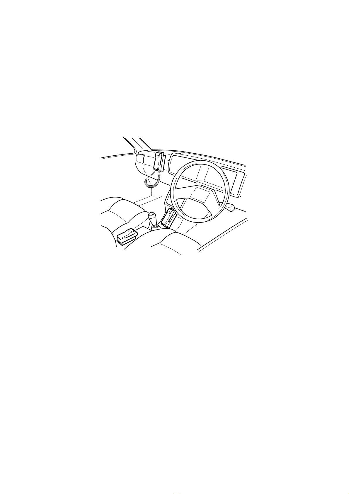
4.2.1 Selecting the Location for the Handsfree Unit
The following points should be considered when choosing a location for the handsfree unit:
Ensure that the location does not obstruct normal operation/functioning of the vehicle.
Ensure that the location does not affect passenger accommodation, or is subject to excessive shocks.
Ensure that the location will allow easy operation of the unit.
Ensure that the location provides a secure fixing for the unit.
Avoid direct exposure to the sun’s rays, or to rain.
Ensure that the location takes due consideration of cable routing requirements.
Considering the points listed above, the recommended locations for mounting the handsfree unit are the
Dashboard, Arm Rest Storage Compartment or the Centre Console.
Figure 2:
Handsfree Cradle Unit Locations 500-0402
Issue 1 Section 4 MCUK960901C8
Revision 0 4 - 2 Service Manual
INSTALLATION GUIDE
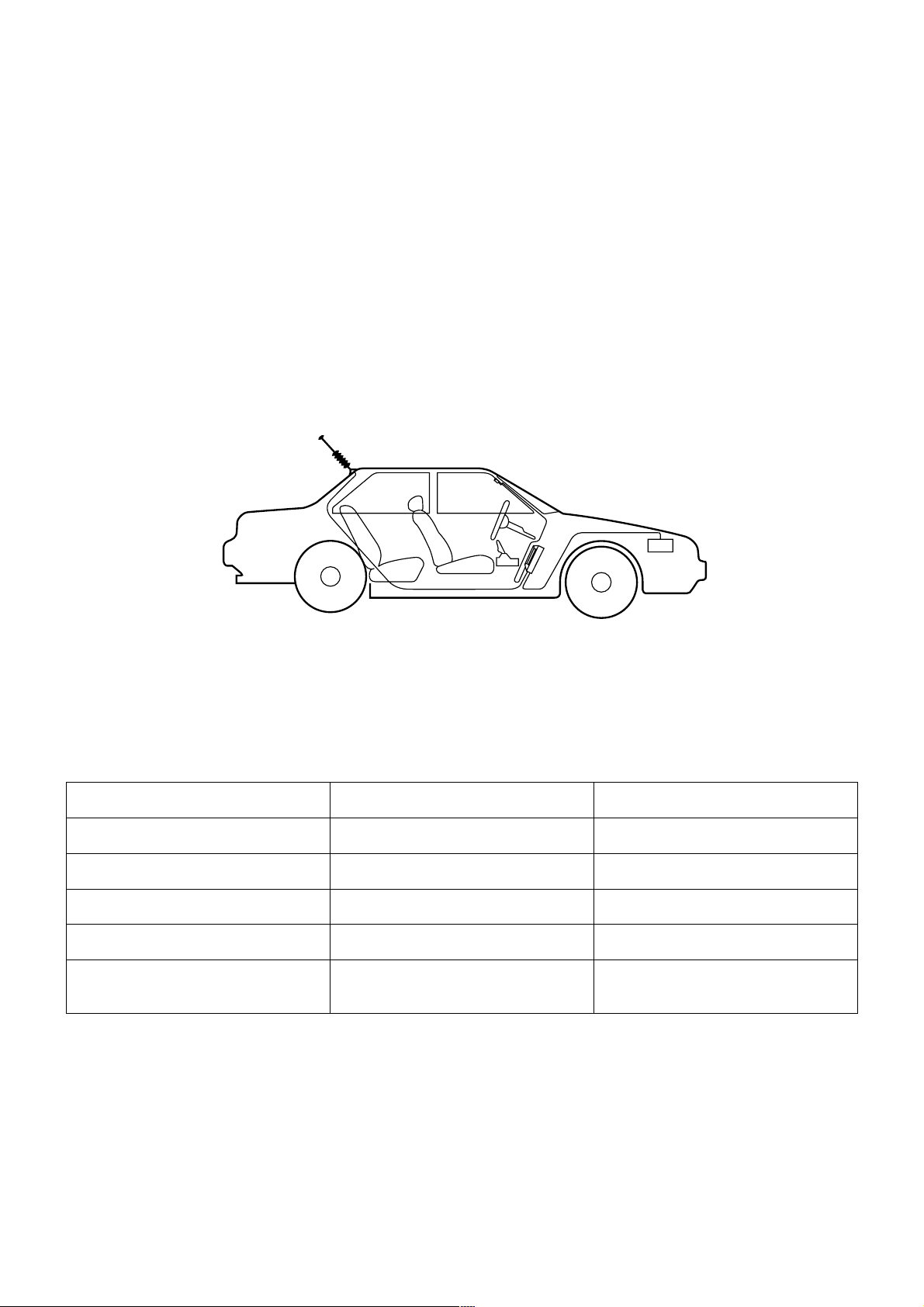
4.2.2 Wiring
Locations for the handsfree unit will vary according to the type of vehicle, as will the routing of power and
interconnecting cables. The following precautions should be observed:
DO NOT install or connect the unit into a positive (+) grounded vehicle. This equipment must be installed into a 12V
negative (-) ground vehicle.
Mount cables to the vehicle so that they are not prone to displacement or disconnection through vibration.
Route cables through existing holes in the dashboard, bulkheads etc. where possible.
Site cables so that contact with moving parts (brake/clutch pedals, seat mechanisms etc.) is avoided.
Site cables as far away as possible from existing cabling, to avoid electrical induction.
Shield cables to protect interference with the vehicle electronics.
When connecting cables to the vehicle circuitry, ensure that the vehicle functions are not affected.
A typical car installation is illustrated below, the actual location of units may vary according to vehicle type.:
Figure 3:
Car installation 500-0403
Wiring guide
Colour Connection Fuse
Black Ground 4A
Blue Ignition 3A
Red Battery (+) 3A
Yellow Radio Mute —
White
Black
NOTE:
The black and white paired wires are designed for use with an antenna compensator. Panasonic do not
manufacture an antenna compensator and do not recommend the use of any third party antenna compensator.
Logic power
Battery (+)
—
MCUK960901C8 Section 4 Issue 1
Service Manual 4 - 3 Revision 0
INSTALLATION GUIDE
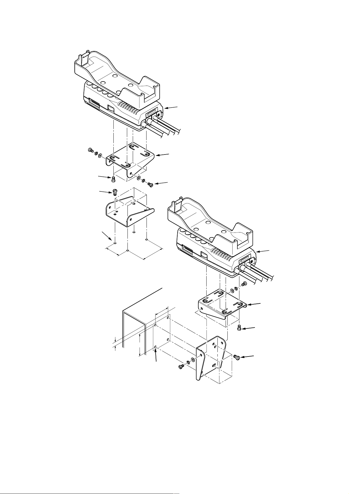
4.2.3 Installation with the Adjustable Angle Bracket
The Adjustable Angle Bracket can be used to install the Handsfree Unit in the following configurations:
HANDSFREE
ADJUSTABLE
ANGLE BRACKET
(XB4 + 10FN) Ø 4 mm
SCREW
SELF-TAPPING SCREW
(XTB4 + 25RFN) Ø 4 mm
Ø 2 mm HOLE
30 mm
16 mm
38 mm
30 mm
SCREW Ø 4 mm
HANDSFREE
ADJUSTABLE
ANGLE BRACKET
SCREW
(XB4 + 10FN) Ø 4 mm
38 mm
SELF-TAPPING SCREW
(XTB4 + 25RFN) Ø 4 mm
Figure 4:
Ø 2 mm HOLE
Adjustable angle bracket configurations 500-0404
Issue 1 Section 4 MCUK960901C8
Revision 0 4 - 4 Service Manual
 Loading...