

Page 1

Table Of Contents
COVER
1 SAFETY PRECAUTIONS
1.1 GENERAL GUIDELINES
1.1.1 LEAKAGE CURRENT COLD CHECK
1.1.2 LEAKAGE CURRENT HOT CHECK (See Figure 1 .)
2 PREVENTION OF ELECTRO STATIC DISCHARGE (ESD) TO ELECTROSTATICALLY SENSITIVE (ES) DEVICES
3 Precaution of Laser Diode
4 General Description
4.1 Operating instructions
5 PREVENTION OF STATIC ELECTRICITY DISCHARGE
5.1 Grounding for electrostatic breakdown prevention
5.1.1 Worktable grounding
5.1.2 Human body grounding
5.1.3 Handling of optical pickup
5.2 Handling Precautions for Traverse Unit (Optical Pickup)
6 Disassembling the Casing and Checking P.C.B.s
6.1 Dissasembly Procedure
6.2 Caseing Parts and P.C.B. Positions
6.3 Top Panel
6.4 Tray
6.5 Front Panel
6.6 Mechanism Unit
6.7 Terminal P.C.B.
6.8 Module P.C.B.
6.9 Front-1 P.C.B. and Front-2 P.C.B.
6.10 Rear panel
6.11 Mother P.C.B.
6.12 Servicing Position
6.12.1 Servicing position of the Module P.C.B. and Terminal P.C.B.
6.12.2 Servicing position of the Mother P.C.B.
7 OPTICAL PICKUP SELF-DIAGNOSIS AND REPLACEMENT PROCEDURE
7.1 Self-diagnosis
7.2 Cautions to Be Used Before Replacing the Optical Pickup Unit and Spindle Motor Assembly
8 Self-Diagnosis Function and Service Modes
8.1 Service Mode Table 1
Page 2

8.2 DVD Self Diagnostic Function-Error Code
8.3 Last Error Code saved during NO PLAY
8.4 Service mode table 2
8.5 Overview of each function
8.5.1 Cumulative operation time display
8.5.2 Servo process display
8.6 Sales demonstration lock function
8.6.1 Setting
8.6.2 Cancellation
8.7 Handling After Completing Repairs
8.7.1 Method
8.7.2 Precautions
9 ASSEMBLING AND DISASSEMBLING THE MECHANISM UNIT
9.1 Disassembly Procedure
9.2 Terminal P.C.B.
9.3 Clamp Plate Unit
9.4 Tray
9.5 Traverse Block
9.6 Traverse Gear
9.7 Optical Pickup Unit
9.7.1 Precautions in optical pickup replacement
9.7.2 Disassembling the Optical Pickup Unit
9.7.3 Cautions to Be Taken When Replacing the Optical Pickup
9.8 Disassembling the Middle Chassis
9.9 Disassembling the Traverse Gear A
9.10 Disassembling the Spindle Motor Unit
10 ADJUSTMENT PROCEDURES
10.1 Service Tools and Equipment
10.2 Important points in adjustment
10.2.1 Important points in optical adjustment
10.2.2 Important points in electrical adjustment
10.3 Storing and Handling Test Discs
10.4 Optical adjustment
10.4.1 Optical pickup tilt adjustment
10.4.1.1 Adjustment procedure
10.4.1.2 Important points
Page 3

10.4.1.3 Check after adjustment
10.4.1.4 Procedure for screw lock
11 Abbreviations
12 Voltage Chart
12.1 Mother P.C.B.
12.2 FRONT 2 P.C.B.
13 BLOCK DIAGRAM
13.1 OVERALL BLOCK DIAGRAM
13.2 POWER BLOCK DIAGRAM
13.3 SERVO BLOCK DIAGRAM
13.4 VIDEO BLOCK DIAGRAM
13.5 AUDIO BLOCK DIAGRAM
14 SCHEMATIC DIAGRAM
14.1 INTERCONNECTION SCHEMATIC DIAGRAM
14.2 POWER SECTION (MOTHER P.C.B. (1/2)) SCHEMATIC DIAGRAM
14.3 OPERATION& FL SECTION (MOTHER P.C.B. (2/2)) SCHEMATIC DIAGRAM
14.4 OVERVIEW SECTION (MODULE P.C.B. (1/6)) SCHEMATIC DIAGRAM
14.5 AVDEC SECTION (MODULE P.C.B (2/6)) SCHEMATIC DIAGRAM
14.6 NODC SECTION (MODULE P.C.B. (3/6)) SCHEMATIC DIAGRAM
14.7 FLASH MEMORY SECTION (MODULE P.C.B. (4/6)) SCHEMATIC DIAGRAM
14.8 AV-INTERFACE SECTION (MODULE P.C.B. (5/6)) SCHEMATIC DIAGRAM
14.9 AUDIO-DAC SECTION (MODULE P.C.B. (6/6)) SCHEMATIC DIAGRAM
14.10 FRONT 1 AND FRONT 2 SCHEMATIC DIAGRAM
14.11 TERMINAL SCHEMATIC DIAGRAM
15 PRINT CIRCUIT BOARD
15.1 MOTHER P.C.B.
15.2 MODULE P.C.B.
15.3 TERMINAL P.C.B.
15.4 FRONT 1 P.C.B.
15.5 FRONT 2 P.C.B.
16 EXPLODED VIEWS
16.1 Casing Parts& Mechanism Section Exploded View
16.2 Mechanism Section Exploded View
16.3 Packing& Accessories Section Exploded View
17 REPLACEMENT PARTS LIST
18 Schematic Diagram for printing with A4
Page 4

19 Additional Contents
19.1 Change of Replacement Parts List
19.1.1 Change of Replacement Parts List
19.1.2 Change of Replacement Parts List
19.1.3 Change of Replacement Parts List
19.1.4 Change of Replacement Parts List
Page 5

Table Of Contents
COVER
1 SAFETY PRECAUTIONS
1.1 GENERAL GUIDELINES
1.1.1 LEAKAGE CURRENT COLD CHECK
1.1.2 LEAKAGE CURRENT HOT CHECK (See Figure 1 .)
2 PREVENTION OF ELECTRO STATIC DISCHARGE (ESD) TO ELECTROSTATICALLY
SENSITIVE (ES) DEVICES
3 Precaution of Laser Diode
4 General Description
4.1 Operating instructions
5 PREVENTION OF STATIC ELECTRICITY DISCHARGE
5.1 Grounding for electrostatic breakdown prevention
5.1.1 Worktable grounding
5.1.2 Human body grounding
5.1.3 Handling of optical pickup
5.2 Handling Precautions for Traverse Unit (Optical Pickup)
6 Disassembling the Casing and Checking P.C.B.s
6.1 Dissasembly Procedure
Page 6

6.2 Caseing Parts and P.C.B. Positions
6.3 Top Panel
6.4 Tray
6.5 Front Panel
6.6 Mechanism Unit
6.7 Terminal P.C.B.
6.8 Module P.C.B.
6.9 Front-1 P.C.B. and Front-2 P.C.B.
6.10 Rear panel
6.11 Mother P.C.B.
6.12 Servicing Position
6.12.1 Servicing position of the Module P.C.B. and Terminal P.C.B.
6.12.2 Servicing position of the Mother P.C.B.
7 OPTICAL PICKUP SELF-DIAGNOSIS AND REPLACEMENT PROCEDURE
7.1 Self-diagnosis
7.2 Cautions to Be Used Before Replacing the Optical Pickup Unit and Spindle Motor Assembly
8 Self-Diagnosis Function and Service Modes
8.1 Service Mode Table 1
8.2 DVD Self Diagnostic Function-Error Code
Page 7

8.3 Last Error Code saved during NO PLAY
8.4 Service mode table 2
8.5 Overview of each function
8.5.1 Cumulative operation time display
8.5.2 Servo process display
8.6 Sales demonstration lock function
8.6.1 Setting
8.6.2 Cancellation
8.7 Handling After Completing Repairs
8.7.1 Method
8.7.2 Precautions
9 ASSEMBLING AND DISASSEMBLING THE MECHANISM UNIT
9.1 Disassembly Procedure
9.2 Terminal P.C.B.
9.3 Clamp Plate Unit
9.4 Tray
9.5 Traverse Block
9.6 Traverse Gear
9.7 Optical Pickup Unit
Page 8

9.7.1 Precautions in optical pickup replacement
9.7.2 Disassembling the Optical Pickup Unit
9.7.3 Cautions to Be Taken When Replacing the Optical Pickup
9.8 Disassembling the Middle Chassis
9.9 Disassembling the Traverse Gear A
9.10 Disassembling the Spindle Motor Unit
10 ADJUSTMENT PROCEDURES
10.1 Service Tools and Equipment
10.2 Important points in adjustment
10.2.1 Important points in optical adjustment
10.2.2 Important points in electrical adjustment
10.3 Storing and Handling Test Discs
10.4 Optical adjustment
10.4.1 Optical pickup tilt adjustment
10.4.1.1 Adjustment procedure
10.4.1.2 Important points
10.4.1.3 Check after adjustment
10.4.1.4 Procedure for screw lock
11 Abbreviations
Page 9

12 Voltage Chart
12.1 Mother P.C.B.
12.2 FRONT 2 P.C.B.
13 BLOCK DIAGRAM
13.1 OVERALL BLOCK DIAGRAM
13.2 POWER BLOCK DIAGRAM
13.3 SERVO BLOCK DIAGRAM
13.4 VIDEO BLOCK DIAGRAM
13.5 AUDIO BLOCK DIAGRAM
14 SCHEMATIC DIAGRAM
14.1 INTERCONNECTION SCHEMATIC DIAGRAM
14.2 POWER SECTION (MOTHER P.C.B. (1/2)) SCHEMATIC DIAGRAM
14.3 OPERATION& FL SECTION (MOTHER P.C.B. (2/2)) SCHEMATIC DIAGRAM
14.4 OVERVIEW SECTION (MODULE P.C.B. (1/6)) SCHEMATIC DIAGRAM
14.5 AVDEC SECTION (MODULE P.C.B (2/6)) SCHEMATIC DIAGRAM
14.6 NODC SECTION (MODULE P.C.B. (3/6)) SCHEMATIC DIAGRAM
14.7 FLASH MEMORY SECTION (MODULE P.C.B. (4/6)) SCHEMATIC DIAGRAM
14.8 AV-INTERFACE SECTION (MODULE P.C.B. (5/6)) SCHEMATIC DIAGRAM
14.9 AUDIO-DAC SECTION (MODULE P.C.B. (6/6)) SCHEMATIC DIAGRAM
Page 10

14.10 FRONT 1 AND FRONT 2 SCHEMATIC DIAGRAM
PV
14.11 TERMINAL SCHEMATIC DIAGRAM
15 PRINT CIRCUIT BOARD
15.1 MOTHER P.C.B.
15.2 MODULE P.C.B.
15.3 TERMINAL P.C.B.
15.4 FRONT 1 P.C.B.
15.5 FRONT 2 P.C.B.
16 EXPLODED VIEWS
16.1 Casing Parts& Mechanism Section Exploded View
16.2 Mechanism Section Exploded View
16.3 Packing& Accessories Section Exploded View
17 REPLACEMENT PARTS LIST
18 Schematic Diagram for printing with A4
19 Additional Contents
19.1 Change of Replacement Parts List
19.1.1 Change of Replacement Parts List
19.1.2 Change of Replacement Parts List
19.1.3 Change of Replacement Parts List
Page 11

19.1.4 Change of Replacement Parts List
Page 12
Service Manual
TOP NEXT
ORDER NO.ODSD020632C2
DVD Player
● DVD-RV32E
DVD-RV32EB
DVD-RV32EG
DVD-RV32EE
Colour
(S).......................Silver Type
(K).......................Black Type
Specifications
Power supply: AC220-240 V, 50 Hz
Power consumption: 11 W
Dimensions: 430 (W)×256 (D)×74.5 (H) mm
(excluding protrusions)
Mass: 2.4 kg
Signal system: PAL 625/50, PAL 525/60, NTSC
Operating temperature range: +5 to+35°C
Operating humidity range: 5 to 90% RH (no condensation)
Region number: Region No.2
(DVD-RV32E/EB/EG)
Region No.5
(DVD-RV32EE only)
Playable disctype:
(1) DVD-Video
DVD-R (DVD-Video compatible)
(2) CD-Audio (CD-DA)
(3) Video CD
(4) CD-R/CD-RW (CD-DA, Video CD formatted discs)
Page 13

(5) MP3
•Maximum number of tracks and groups recognizable:999 tracks and 99 groups
•Compatible compression rate:between 32 kbps and 320 kbps
Video output:
Output level:
Output terminal: Pin jack/ AV
Number of terminals: 1 system
1 Vp-p (75Ω)
S video output:
Y output level:
C output level:
1 Vp-p (75Ω)
NTSC: 0.286 Vp-p (75Ω)
PAL: 0.300 Vp-p (75Ω)
Output terminal: S terminal/AV
Number of terminals: 1 system
RGB video output:
R output level:
G output lebel:
B output level
Output terminal: AV1
Number of terminals: 1 system
0.7 Vp-p (75Ω)
0.7 Vp-p (75Ω)
0.7 Vp-p (75Ω)
Audio output:
Output level: 2 Vrms (1 kHz, 0 dB)
Output terminal: Pin jack/ AV
Number of terminals:
2CH: 1 system
Subwoofer output (0.1 ch): 1 system
Audio performance:
(1) Frequency response:
•DVD (linear audio): 4 Hz-22 kHz (48 kHz sampling)
•CD audio: 4 Hz-20 kHz
(2) S/N ratio:
•CD audio: 115 dB
(3) Dynamic range:
•DVD (linear audio): 97 dB
•CD audio: 97 dB
(4) Total harmonic distortion:
•CD audio: 0.0025%
4 Hz-44 kHz (96 kHz sampling)
Digital audio output:
Optical digital output: Optical terminal
Pickup
Wave length: 658 nm/790 nm
Laser power: CLASS 2/CLASS 1
Power consumption in standby mode:
approx. 4 W
Note:
Specifications are subject to change without notice.
Mass and dimensions are approximate.
Page 14

© 2002 Matsushita Electric Industrial CO., Ltd. All rights reserved. Unauthorized copying and distribution is a violation of law.
TOP NEXT
Page 15

1 SAFETY PRECAUTIONS
TOP PREVIOUS NEXT
1.1 GENERAL GUIDELINES
1.1.1 LEAKAGE CURRENT COLD CHECK
1.1.2 LEAKAGE CURRENT HOT CHECK (See Figure 1 .)
TOP PREVIOUS NEXT
Page 16

1.1 GENERAL GUIDELINES
TOP PREVIOUS NEXT
1. When servicing, observe the original lead dress. If a short circuit is found, replace all parts which
have been overheated or damaged by the short circuit.
2. After servicing, see to it that all the protective devices such as insulation barriers, insulation
papers shields are properly installed.
3. After servicing, make the following leakage current checks to prevent the customer from being
exposed to shock hazards.
1.1.1 LEAKAGE CURRENT COLD CHECK
1.1.2 LEAKAGE CURRENT HOT CHECK (See Figure 1 .)
TOP PREVIOUS NEXT
Page 17
1.1.1 LEAKAGE CURRENT COLD CHECK
TOP PREVIOUS NEXT
1. Unplug the AC cord and connect a jumper between the two prongs on the plug.
2. Measure the resistance value, with an ohmmeter, between the jumpered AC plug and each
exposed metallic cabinet part on the equipment such as screwheads, connectors, control shafts,
etc. When the exposed metallic part has a return path to thechassis, the reading should be
between 1MΩ and 5.2MΩ.
When the exposed metal does not have a return path to the chassis, the reading must be
.
Figure 1
TOP PREVIOUS NEXT
Page 18

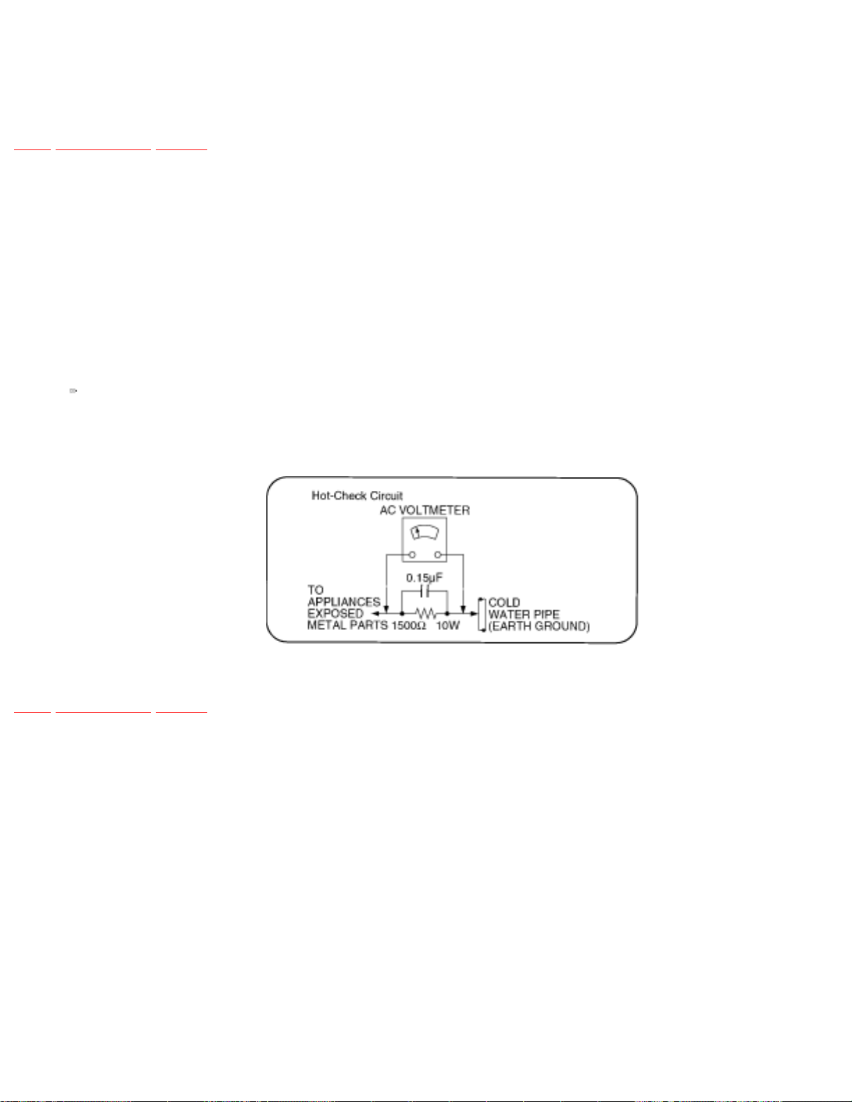
1.1.2 LEAKAGE CURRENT HOT CHECK (See
Figure 1 .)
TOP PREVIOUS NEXT
1. Plug the AC cord directly into the AC outlet. Do not use an isolation transformer for this check.
2. Connect a 1.5kΩ, 10 watts resistor, in parallel with a 0.15μF capacitors, between each exposed
metallic part on the set and a good earth ground such as a water pipe, as shown in
3. Use an AC voltmeter, with 1000 ohms/volt or more sensitivity, to measure the potential across
the resistor.
4. Check each exposed metallic part, and measure the voltage at each point.
5. Reverse the AC plug in the AC outlet and repeat each of the above measurements.
Figure 1 .
6. The potential at any point should not exceed 0.75 volts RMS. A leakage current tester (Simpson
Model 229 or equivalent) may be used to make the hot checks, leakage current mu3st not exceed
1/2 milliamp. In case a measurement is outsideof the limits specified, there is a possibility of a
shock hazard, and the equipment should be repaired and rechecked before it is returned to the
customer.
TOP PREVIOUS NEXT
Page 19

2 PREVENTION OF ELECTRO STATIC
DISCHARGE (ESD) TO ELECTROSTATICALLY
SENSITIVE (ES) DEVICES
TOP PREVIOUS NEXT
Some semiconductor (solid state) devices can be damaged easily by static electricity. Such components
commonly are called Electrostatically Sensitive (ES) Devices. Examples of typical ES devices are
integrated circuits and some field-effect transistorsand semiconductor "chip" components. The following
techniques should be used to help reduce the incidence of component damage caused by electro static
discharge (ESD).
1. Immediately before handling any semiconductor component or semiconductor-equipped
assembly, drain off any ESD on your body by touching a known earth ground. Alternatively,
obtain and wear a commercially available dischargingESD wrist strap, which should be removed
for potential shock reasons prior to applying power to the unit under test.
2. After removing an electrical assembly equipped with ES devices, place the assembly on a
conductive surface such as alminum foil, to prevent electrostatic charge buildup or exposure of
the assembly.
3. Use only a grounded-tip soldering iron to solder or unsolder ES devices.
4. Use only an anti-static solder removal device. Some solder removal devices not classified as
"anti-static (ESD protected)" can generate electrical charge sufficient to damage ES devices.
5. Do not use freon-propelled chemicals. These can generate electrical charges sufficient to damage
ES devices.
6. Do not remove a replacement ES device from its protective package until immediately before you
are ready to install it. (Most replacement ES devices are packaged with leads electrically shorted
together by conductive foam, alminum foil or comparableconductive material).
7. Immediately before removing the protective material from the leads of a replacement ES device,
touch the protective material to the chassis or circuit assembly into which the device will be
installed.
Caution
Page 20

Be sure no power is applied to the chassis or circuit, and observe all other safety precautions.
8. Minimize bodily motions when handling unpackaged replacement ES devices. (Otherwise
hamless motion such as the brushing together of your clothes fabric or the lifting of your foot
from a carpeted floor can generate static electricity (ESD) sufficient todamage an ES device).
TOP PREVIOUS NEXT
Page 21
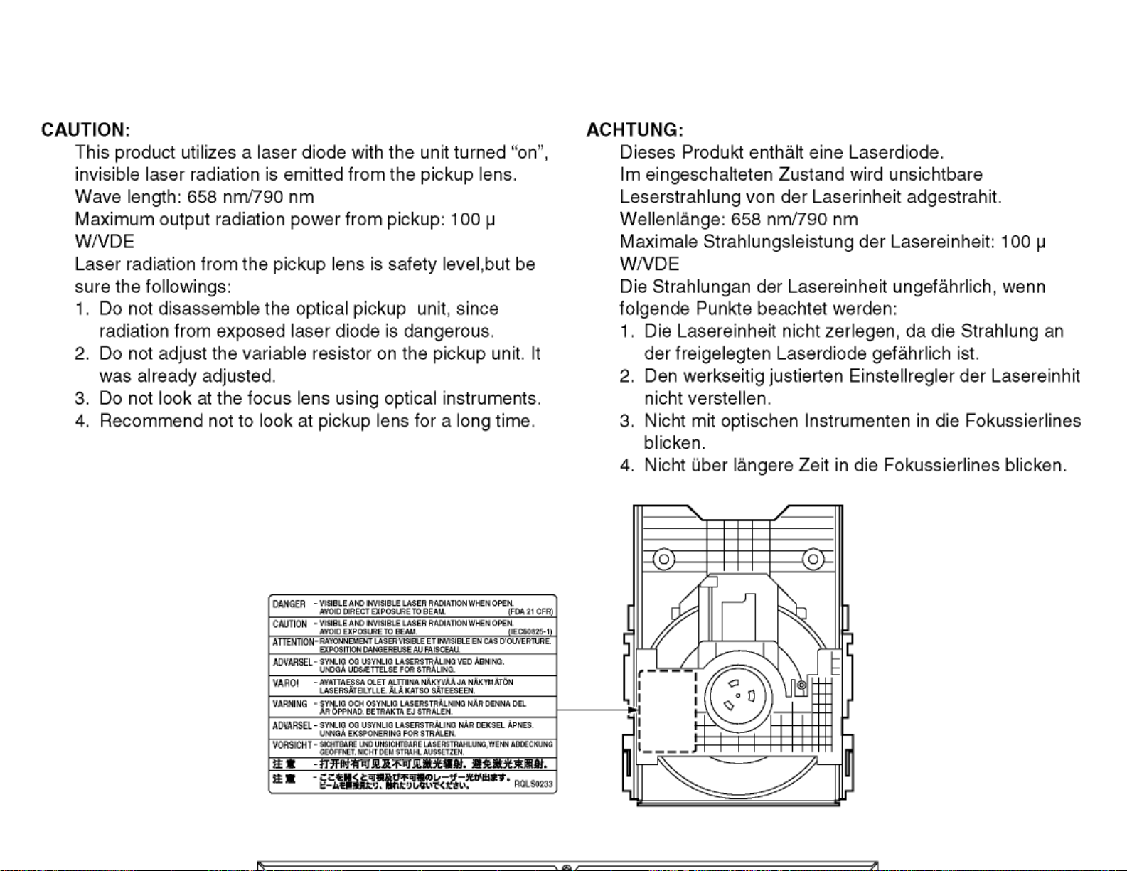
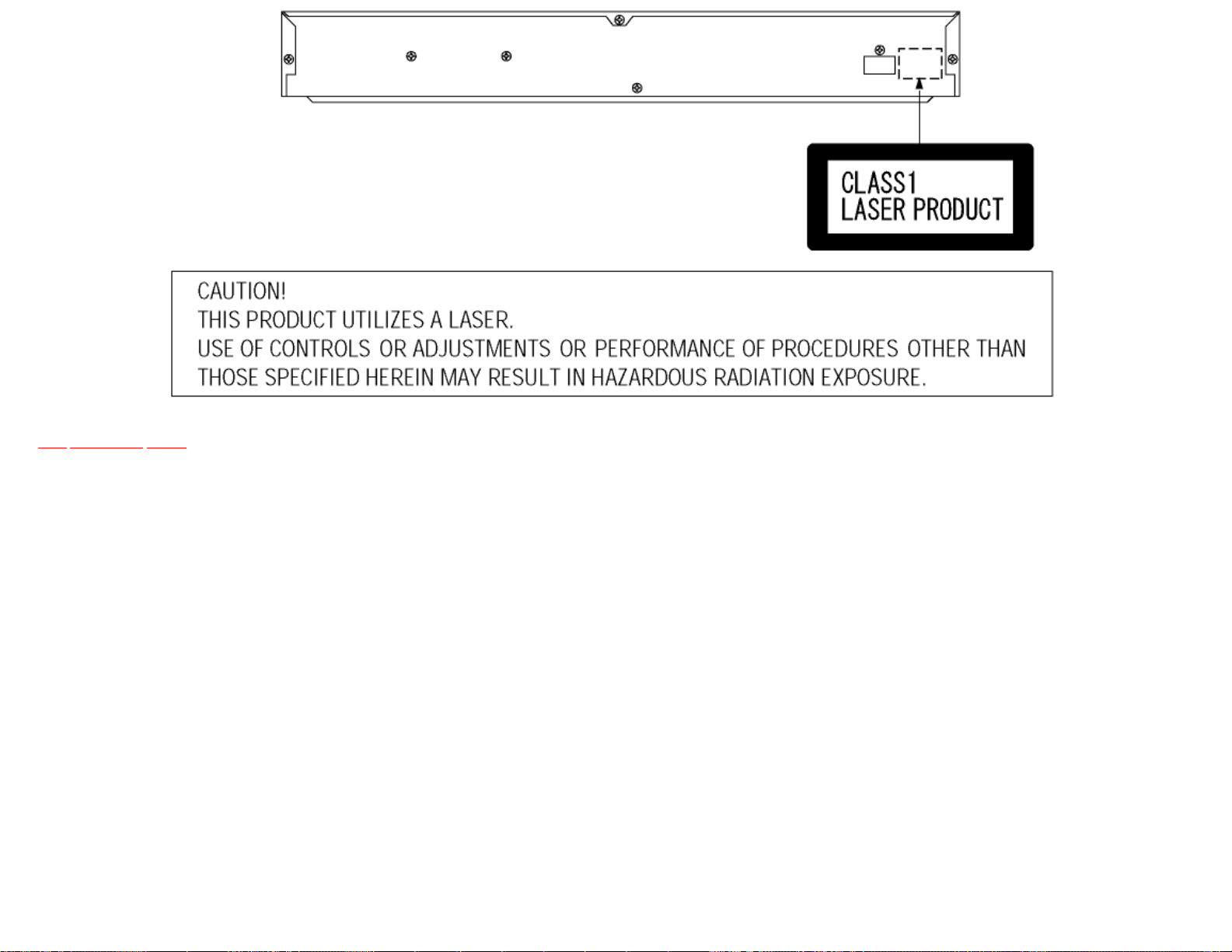
3 Precaution of Laser Diode
TOP PREVIOUS NEXT
Page 22
TOP PREVIOUS NEXT
Page 23

4 General Description
TOP PREVIOUS NEXT
4.1 Operating instructions
TOP PREVIOUS NEXT
Page 24

4.1 Operating instructions
TOP PREVIOUS NEXT
TOP PREVIOUS NEXT
Page 25

5 PREVENTION OF STATIC ELECTRICITY
DISCHARGE
TOP PREVIOUS NEXT
The laser diode in the traverse unit (optical pickup) may brake down due to static electricity of clothes or
human body. Use due caution to electrostatic breakdown when servicing and handling the laser diode.
5.1 Grounding for electrostatic breakdown prevention
5.1.1 Worktable grounding
5.1.2 Human body grounding
5.1.3 Handling of optical pickup
5.2 Handling Precautions for Traverse Unit (Optical Pickup)
TOP PREVIOUS NEXT
Page 26

5.1 Grounding for electrostatic breakdown
prevention
TOP PREVIOUS NEXT
Some devices such as the DVD player use the optical pickup (laser diode) and the optical pickup will be
damaged by static electricity in the working environment. Proceed servicing works under the working
environment where grounding works is completed.
5.1.1 Worktable grounding
5.1.2 Human body grounding
5.1.3 Handling of optical pickup
TOP PREVIOUS NEXT
Page 27

5.1.1 Worktable grounding
TOP PREVIOUS NEXT
1. Put a conductive material (sheet) or iron sheet on the area where the optical pickup is placed, and
ground the sheet.
TOP PREVIOUS NEXT
Page 28
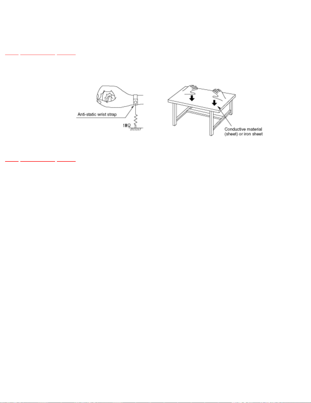
5.1.2 Human body grounding
TOP PREVIOUS NEXT
1. Use the anti-static wrist strap to discharge the static electricity form your body.
TOP PREVIOUS NEXT
Page 29

5.1.3 Handling of optical pickup
TOP PREVIOUS NEXT
1. To keep the good quality of the optical pickup maintenance parts during transportation and before
installation, the both ends of the laser diode are short-circuited. After replacing the parts with
new ones, remove the short circuit accordingto the correct procedure. (See this Technical Guide.)
2. Do not use a tester to check the laser diode for the optical pickup. Failure to do so will damage
the laser diode due to the power supply in the tester.
TOP PREVIOUS NEXT
Page 30

5.2 Handling Precautions for Traverse Unit
(Optical Pickup)
TOP PREVIOUS NEXT
1. Do not give a considerable shock to the traverse unit (optical pickup) as it has an extremely highprecise structure.
2. When replacing the optical pickup, install the flexible cable and cut its short land with a nipper.
See the optical pickup replacement procedure in this Technical Guide. Before replacing the
traverse unit, remove the short pin for preventingstatic electricity and install a new unit. Connect
the connector as short times as possible.
3. The flexible cable may be cut off if an excessive force is applied to it. Use caution when handling
the cable.
4. The half-fixed resistor for laser power adjustment cannot be adjusted. Do not turn the resistor.
TOP PREVIOUS NEXT
Page 31

6 Disassembling the Casing and Checking P.C.B.s
TOP PREVIOUS NEXT
6.1 Dissasembly Procedure
6.2 Caseing Parts and P.C.B. Positions
6.3 Top Panel
6.4 Tray
6.5 Front Panel
6.6 Mechanism Unit
6.7 Terminal P.C.B.
6.8 Module P.C.B.
6.9 Front-1 P.C.B. and Front-2 P.C.B.
6.10 Rear panel
6.11 Mother P.C.B.
6.12 Servicing Position
6.12.1 Servicing position of the Module P.C.B. and Terminal P.C.B.
6.12.2 Servicing position of the Mother P.C.B.
TOP PREVIOUS NEXT
Page 32

6.1 Dissasembly Procedure
TOP PREVIOUS NEXT
TOP PREVIOUS NEXT
Page 33

6.2 Caseing Parts and P.C.B. Positions
TOP PREVIOUS NEXT
TOP PREVIOUS NEXT
Page 34

6.3 Top Panel
TOP PREVIOUS NEXT
1. Unscrew the screws.
TOP PREVIOUS NEXT
Page 35

6.4 Tray
TOP PREVIOUS NEXT
1. Pull the tray out of the mechanism unit. Remove the gear and install it onto a screwdriver to
make a gear jig.
2. Insert the gear jig into the tray open/close hole.
3. Turn the gear jig counterclockwise to open the tray.
4. Remove the tray dressing from the tray section.
Page 36

TOP PREVIOUS NEXT
Page 37

6.5 Front Panel
TOP PREVIOUS NEXT
1. Release the tabs.
2. Remove the connectors.
TOP PREVIOUS NEXT
Page 38

6.6 Mechanism Unit
TOP PREVIOUS NEXT
1. Unscrew the screws.
2. Remove the connectors.
3. Pull out the mechanism unit vertically.
TOP PREVIOUS NEXT
Page 39

6.7 Terminal P.C.B.
TOP PREVIOUS NEXT
1. Unscrew the screw.
2. Remove the solders.
3. Remove the connector.
TOP PREVIOUS NEXT
Page 40

6.8 Module P.C.B.
TOP PREVIOUS NEXT
1. Unscrew the screws.
2. Remove the connectors.
3. Pull out the module PCB vertically.
TOP PREVIOUS NEXT
Page 41

6.9 Front-1 P.C.B. and Front-2 P.C.B.
TOP PREVIOUS NEXT
1. Unscrew the screws.
2. Release the tabs.
TOP PREVIOUS NEXT
Page 42

6.10 Rear panel
TOP PREVIOUS NEXT
1. Unscrew the screws
2. Release the tabs.
TOP PREVIOUS NEXT
Page 43

6.11 Mother P.C.B.
TOP PREVIOUS NEXT
1. Unscrew the screws.
TOP PREVIOUS NEXT
Page 44

6.12 Servicing Position
TOP PREVIOUS NEXT
6.12.1 Servicing position of the Module P.C.B. and Terminal P.C.B.
6.12.2 Servicing position of the Mother P.C.B.
TOP PREVIOUS NEXT
Page 45

6.12.1 Servicing position of the Module P.C.B.
and Terminal P.C.B.
TOP PREVIOUS NEXT
TOP PREVIOUS NEXT
Page 46

6.12.2 Servicing position of the Mother P.C.B.
TOP PREVIOUS NEXT
TOP PREVIOUS NEXT
Page 47

7 OPTICAL PICKUP SELF-DIAGNOSIS AND
REPLACEMENT PROCEDURE
TOP PREVIOUS NEXT
7.1 Self-diagnosis
7.2 Cautions to Be Used Before Replacing the Optical Pickup Unit and Spindle Motor Assembly
TOP PREVIOUS NEXT
Page 48

7.1 Self-diagnosis
TOP PREVIOUS NEXT
The optical pickup self-diagnosis function and tilt adjustment check function have been included in this
unit. When repairing, use the following procedure for effective Self-diagnosis and tilt adjustment.Be
sure to use the self-diagnosis functionbefore replacing the optical pickup when "NO DISC" is displayed.
As a guideline, you should replace the optical pickup when the value of the laser drive current is more
than 55.
Note:
Press the power button to turn on the power, and check the value within three minutes before the unit
warms up. (Otherwise, the result will be incorrect.)
Page 49

TOP PREVIOUS NEXT
Page 50

7.2 Cautions to Be Used Before Replacing the
Optical Pickup Unit and Spindle Motor Assembly
TOP PREVIOUS NEXT
Before replacing the optical pickup unit and spindle motor assembly, check the total using hours for
each of them. The checking method is as follows:
Cautions to be taken when replacing the optical pickup
The optical pickup may break down due to the static electricity of human body. Take proper protection
measures against static electricity before repairing the parts around the optical pickup. (See the page
describing the PREVENTION OF STATIC ELECTRICITYDISCHARGE.)
1. Do not touch the areas around the laser diode and actuator.
2. Do not judge the laser diode with a tester. (The tester will be damaged easily.)
3. It is recommended to use a destaticized soldering iron for short-circuiting or removing the laser
diode. (Recommended soldering iron) HAKKO ESD Product
Page 51

4. Solder the land of the flexible cable in the optical pickup.
Note:
❍ When using a soldering iron which is not destaticized, short-circuit the terminal face of
the flexible case with a clip. After that, short-circuit the land.
❍ After the repairing work is completed, remove the solder according to the correct
procedure shown in this Technical Guide.
TOP PREVIOUS NEXT
Page 52

8 Self-Diagnosis Function and Service Modes
TOP PREVIOUS NEXT
8.1 Service Mode Table 1
8.2 DVD Self Diagnostic Function-Error Code
8.3 Last Error Code saved during NO PLAY
8.4 Service mode table 2
8.5 Overview of each function
8.5.1 Cumulative operation time display
8.5.2 Servo process display
8.6 Sales demonstration lock function
8.6.1 Setting
8.6.2 Cancellation
8.7 Handling After Completing Repairs
8.7.1 Method
8.7.2 Precautions
TOP PREVIOUS NEXT
Page 53

8.1 Service Mode Table 1
TOP PREVIOUS NEXT
The service modes can be activated by pressing various button combination on the player and remote
control unit.
Player buttons Remote control unit buttons Application Note
PAUSE
+
OPEN/CLOSE
0 Displaying the UHF display F_ _ _ Refer to section 8.2. Self-Diagnosis
Function (UHF Display).
5 Jitter check, tilt adjustment
*Display shows J_xxx_yyy_zz
"yyy" and "zz" shown to the right have
nothing to do with the jitter value. "yyy"
is the error counter, while "zz" is the
focusdrive value.
Refer to section 10.4. for Optical Pickup
Tilt Adjustment Procedure.
6 Checking the region numbers and
broadcast system
7 Checking the program version Check the IC6302 FLASH ROM
9 Lighting Confirmation Function of
Display Tube
DISPLAY Checking the laser drive current Refer to section 9 Optical Pickup
PAUSE Writing the laser drive current value after
replacing the optical pickup (do not use
for anything other than optical pickup
replacement)
Refer to section 10.4. Optical Pickup
Tilt Adjustment
program.
Replacement Procedure.
PAUSE
SKIP/
SEARCH<<
OPEN/CLOSE
TOP PREVIOUS NEXT
Initializing the DVD player
(restoring factory preset settings)
Refer to section 8.4. Initializing the
DVD player.
Page 54

8.2 DVD Self Diagnostic Function-Error Code
TOP PREVIOUS NEXT
Error
Code
U11 Focus error
H01 Tray loading error
H02 Spindle servo error (Spindle servo, DSC
H03 Traverse servo error
H04 Tracking servo error
H05 Seek error
H06 Power error Cannot switch off the
H07 Spindle motor drive error
F103 Illegal highlight Position Big possibility of disc
Error Content Additional error
explanation
(IC2001) SP motor, CLV
servo error)
power because of the panel
and system computer
communication error
specification violation
during highlight display
Defect 1 Defect 2 Defect 3 Defect 4
DISC
F498 No communication
between Front Micro
Computer and Main
Micro Computer after
power on
F499 No response from Main
Micro Computer when
key code is sent from
Front Micro Computer to
Main Micro Computer
F4FF Force initialize failure
(time out)
F500 DSC error DSC (IC2001) stops in the
F501 DSC not Ready DSC-system computer
IC communication is NG
FROM(IC3080) and/or
Firmware in FROM is NG
Main Micro Computer
hangs up
occurence of servo error
(starup, focus error, etc)
communication error
(Communication failure
caused by idling of DSC)
EEPROM
(IC3066)
Optical
pickup
ADSC
(IC2001)
CPU
(IC6001)
ADSC
(IC2001)
CPU
(IC6001)
FEP
(IC5201)
FEP
(IC5201)
ADSC
(IC2001)
servo drive
Page 55

F502 DSC Time out error Similar disposal as F500 Optical
pickup
ADSC
(IC2001)
FEP
(IC5201)
servo drive
F503 DSC communication
Failure
F505 DSC Attention error Similar disposal as F500 Optical
F506 Invalid media Disc is flipped over, TOC
F600 Access failure to
management information
caused by demodulation
error
F601 Indeterminate sector ID
requested
F602 Access failure to LEAD-
IN caused by
demodulation error
Communication error
(result error occured
although communication
command was sent)
unreadable, incompatible
disc
Operation stopped because
navigation data is not
accessible caused by the
demodulation defect
Operation stopped caused
by the request to access
abnormal ID data
LEAD IN data unreadable
ADSC
(IC2001)
pickup
DISC FEP
ODC
(IC2001)
ODC
(IC2001)
FEP
(IC5201)
ADSC
(IC2001)
(IC5201)
FEP
(IC5201)
FEP
(IC5201)
EEPROM
(IC3066)
FEP
(IC5201)
ADSC
(IC2001)
ADSC
(IC2001)
ADSC
(IC2001)
servo drive
ODC
(IC2001)
F603 Access failure to
KEYDET caused by
demodulation error
F610 ODC abnormality No permission for
F611 6626 QCODE don’t read
Error
F612 No CRC OK for a
specific time
F630 No reply to KEY DET
enquiry
F631 CPPM KEY DET is not
available till the FILE
terminal
F632 CPPM KEY DET is not
available
F103 Illegal highlight Position Big possibility of disc
Access failure to CSS data
of disc
command execution
Access failure to seek
address in CD series
Access failure to ID data in
DVD series
(for internal use only)
(CPPM file system is
unreadable caused by
scratches)
Been revoked or falsified DISC EEPROM
specification violation
during highlight display
ODC
(IC2001)
ODC
(IC2001)
ODC
(IC2001)
DISC CPPM
DISC
(*1)
CPPM
(IC3066)
(*1)
F700 MBX overflow When replying message to
disc manager
F701 Message command does
not end
Next message is sent
before replying to disc
manager
Page 56

F702 Message command
changes
Message is changed before
it is sent as a reply to disc
manager
F880 Task number is not
appropriate
F890 Sending message when
message is being sent to
AV task
F891 Message couldn’t be sent
to AV task
F893 FROM falsification
F894 EEPROM abnormality
F895 Language area
abnormality
F896 No existence model Firm version agreement
F897 Initialize is not completed Initialize completion check
Message coming from a
non-existing task
Sending message to AV
task
Begin sending message to
AV task
Firm version agreement
check for factory preset
setting failure prevention
check for factory preset
setting failure prevention
for factory preset setting
failure prevention
FROM
(IC3080)
EEPROM
(IC3066)
FROM
(IC3080)
Jumper (*2)
communication on lone
CPU
(IC6001)
Serial
Jumper (*2)
F8A0 Message command is not
appropriate
Begin sending message to
AV task
Note:
An error code will be canceled if a power supply is turned OFF.
*1: CPPM is the copy guard function beforehand written in the disk for protection of copyrights.
*2: Jumper ... R6012, R6014 and R6016.
TOP PREVIOUS NEXT
Page 57

8.3 Last Error Code saved during NO PLAY
TOP PREVIOUS NEXT
Error code Error Content System computer Setting task System computer internal
error code
F0BF 6) Cannot playback because
physical layer is not recoginizable
F0C0 8) DVD: Cannot playback because
it is not DVD Video/Adio/VR
F0C1 9) DVD: Prohibited by the
restricted region code
F0C2 A) DVD: PAL restricted playback PCND_NOPLAY PAL 0x90 DiscManager 0xDOC2
F0C3 B) DVD: Parental lock setting
prohibits the playback of the entire
title
F0C4 C) VCD: Prohibited because it is in
PHOTO CD fromat
F0C5 VCD/CD: Prohibited because it is
CDROM without CD-DA
PCND_NOPLAY PHYSICAL 0x50 DriveManager 0xDOBF
PCND_NOPLAY VIDEO 0x70 DiscManager 0xDOC0
PCND_NOPLAY RCD 0x80 DiscManager 0xDOC1
PCND_NOPLAY PTL 0xA0 DiscManager 0xDOC3
PCND_NOPLAY PHOTO CD 0xB0 DiscManager 0xDOC4
PCND_NOPLAY CDROM 0xC0 DiscManager 0xDOC5
TOP PREVIOUS NEXT
Page 58

8.4 Service mode table 2
TOP PREVIOUS NEXT
Pressing various button combinations on the player and remote control unit can activate the service
modes.
Page 59

Page 60

TOP PREVIOUS NEXT
Page 61

8.5 Overview of each function
TOP PREVIOUS NEXT
8.5.1 Cumulative operation time display
8.5.2 Servo process display
TOP PREVIOUS NEXT
Page 62

8.5.1 Cumulative operation time display
TOP PREVIOUS NEXT
1. Operation/display
Key operations are as follows.
Laser operation time ............. In STOP mode, main unit PAUSE+FWD-SKIP+ remote controller
[5]
Spindle motor operation time ..... In STOP mode, main unit PAUSE+FWD-SKIP+ remote
controller [6]
To reset the timer, perform the following while displaying the time with above key operation.
Laser operation time ............. In STOP mode, main unit STOP+FWD-SKIP+ remote controller
[5]
Spindle motor operation time ..... In STOP mode, main unit STOP+FWD-SKIP+ remote
controller [6]
2. How to utilize
Reference information in fault diagnosis of laser or spindle motor system
Review of faulty point in repeated repair
TOP PREVIOUS NEXT
Page 63

8.5.2 Servo process display
TOP PREVIOUS NEXT
1. Operation/display
While the player is in STOP mode, perform the specified key operation to display the servo
process number on FL.
When the display does not change from the error indication, press Open/Close key to show the
servo process number.
Key operation: In STOP mode, main unit PAUSE+FWD- SKIP+ remote controller [7]
TOP PREVIOUS NEXT
Page 64

8.6 Sales demonstration lock function
TOP PREVIOUS NEXT
This function prevents discs from being lost when the unit is used for sales demonstrations by disabling
the disc eject function. "LOCKED" is displayed on the unit, and ordinary operation is disabled.
8.6.1 Setting
8.6.2 Cancellation
TOP PREVIOUS NEXT
Page 65

8.6.1 Setting
TOP PREVIOUS NEXT
The sales demonstration lock is set by simultaneously pressing STOP button on the player and POWER
button on the remote control unit.
TOP PREVIOUS NEXT
Page 66

8.6.2 Cancellation
TOP PREVIOUS NEXT
The lock can be cancelled by the same procedure as used in setting. ("UNLOCKED" is displayed on
cancellation. Disconnecting the power cable from power outlet does not cancel the lock.)
TOP PREVIOUS NEXT
Page 67

8.7 Handling After Completing Repairs
TOP PREVIOUS NEXT
Use the following procedure after completing repairs.
8.7.1 Method
8.7.2 Precautions
TOP PREVIOUS NEXT
Page 68

8.7.1 Method
TOP PREVIOUS NEXT
Confirm that the power is turned on:
1. Press the "OPEN/CLOSE" button to close the tray.
2. Press the "POWER" button to turn off the power.
3. Disconnect the power plug from the outlet.
TOP PREVIOUS NEXT
Page 69

8.7.2 Precautions
TOP PREVIOUS NEXT
Do not disconnect the power plug from the outlet with the tray still open, then close the tray manually.
TOP PREVIOUS NEXT
Page 70

9 ASSEMBLING AND DISASSEMBLING THE
MECHANISM UNIT
TOP PREVIOUS NEXT
9.1 Disassembly Procedure
9.2 Terminal P.C.B.
9.3 Clamp Plate Unit
9.4 Tray
9.5 Traverse Block
9.6 Traverse Gear
9.7 Optical Pickup Unit
9.7.1 Precautions in optical pickup replacement
9.7.2 Disassembling the Optical Pickup Unit
9.7.3 Cautions to Be Taken When Replacing the Optical Pickup
9.8 Disassembling the Middle Chassis
9.9 Disassembling the Traverse Gear A
9.10 Disassembling the Spindle Motor Unit
TOP PREVIOUS NEXT
Page 71

9.1 Disassembly Procedure
TOP PREVIOUS NEXT
TOP PREVIOUS NEXT
Page 72

9.2 Terminal P.C.B.
TOP PREVIOUS NEXT
1. Unscrew the screws.
2. Remove the solders.
3. Remove the connectors.
TOP PREVIOUS NEXT
Page 73

9.3 Clamp Plate Unit
TOP PREVIOUS NEXT
1. Push the stopper with hand to slide the tabs and remove the clamp plate unit.
TOP PREVIOUS NEXT
Page 74

9.4 Tray
TOP PREVIOUS NEXT
1. Lift the tray.
<Precautions in reassembling the tray>
•Reassemble the tray so that it is in the backmost position.
1. Turn traverse gear until cam gear leaver comes to the lever adjusting position at the end of
mechanical chassis unit.
Page 75

2. Check the position of convex phase on back of the tray, and that of concave phase on drive gear.
A. Place the tray on the unit from rearward.
Page 76

B. Inch the tray frontward until convex phase and concave phase mate.
Caution:
Make sure to mate convex phase and concave phase properly, so that the gap between turntable and tray
becomes 5mm or less.
TOP PREVIOUS NEXT
Page 77

9.5 Traverse Block
TOP PREVIOUS NEXT
1. Lift the traverse block while spreading the hook of the mechanical chassis unit.
2. Disengage the tabs from the holes of the mechanical chassis unit.
TOP PREVIOUS NEXT
Page 78

9.6 Traverse Gear
TOP PREVIOUS NEXT
1. Disengage the tabs from the traverse gear.
2. Remove the traverse gears B and C.
<Precautions in reassembling the traverse block>
•Take the following precautions when reassembling the traverse block.
A. Turn traverse gear on the traverse block to let trigger lever turn rightward. (Front view)
B. Bring cam gear lever to the lever adjusting position at the end of mechanical chassis unit.
Page 79

C. Put tabs A and B into slots A and B respectively.
Place tabs C into hooks to mount the traverse block on mechanical chassis unit. (Slot A...
Mechanical chassis unit, Slot B... Cam gear)
TOP PREVIOUS NEXT
Page 80

9.7 Optical Pickup Unit
TOP PREVIOUS NEXT
1. Unscrew the screws.
2. Remove the spring holders and the springs.
3. Pull out the drive shaft and guide shaft.
9.7.1 Precautions in optical pickup replacement
9.7.2 Disassembling the Optical Pickup Unit
9.7.3 Cautions to Be Taken When Replacing the Optical Pickup
TOP PREVIOUS NEXT
Page 81

9.7.1 Precautions in optical pickup replacement
TOP PREVIOUS NEXT
The optical pickup can be damaged by static electricity from you body. Be sure to take static electricity
countermeasures when working around the optical pickup. (Refer to the related page in this Manual
about the countermeasures.)
1. Do not touch laser diode, actuator and their peripheries.
2. Do not use tester to check laser diode. (Laser diode can be damaged easily.)
3. The use of soldering iron with anti-static feature is recommended when providing short-circuit to
laser diode or when removing it.
4. Solder the land on flexible cable of optical pickup unit.
Caution
❍ When using the soldering iron without anti-static feature, short-circuit the flexible cable
terminal with a clip before short-circuiting the land.
❍ After intended repair is finished, remove the solder for short-circuit of laser diode in a
correct way following the procedures described in this Manual.
TOP PREVIOUS NEXT
Page 82

9.7.2 Disassembling the Optical Pickup Unit
TOP PREVIOUS NEXT
1. Remove the 2 screws A and remove the TRV feed rack.
2. Remove the screw B and remove the Terminal FPC.
3. Remove the optical pickup.
Fig. 1
TOP PREVIOUS NEXT
Page 83

9.7.3 Cautions to Be Taken When Replacing the
Optical Pickup
TOP PREVIOUS NEXT
● An antistatic flexible sheet (FPC) is connected with the new optical pickup.
Replace the optical pickup according to the following procedure.
1. Install the Terminal FPC, TRV feed rack on the optical pickup. (See
2. Install the Terminal FPC in the connector on the Intermediate P.C.B..
Fig. 2
Fig. 1 )
3. Install the optical pickup unit, spring, drive shaft, guide shaft, rubber cushion, and spring holder
on the traverse block.
Fig. 3
Page 84

Cautions to be taken when assembling the unit: Install the pickup unit so that it is located at the
rear end of the guide shaft.)
4. Cut the antistatic flexible sheet for the optical pickup unit.
Fig. 4
Page 85

TOP PREVIOUS NEXT
Page 86

9.8 Disassembling the Middle Chassis
TOP PREVIOUS NEXT
1. Remove the holder pins.
2. Remove the tab.
3. It lifts while pulling it in the direction of the arrow.
TOP PREVIOUS NEXT
Page 87

9.9 Disassembling the Traverse Gear A
TOP PREVIOUS NEXT
1. Unscrew the screw.
2. Remove the traverse gear A.
TOP PREVIOUS NEXT
Page 88

9.10 Disassembling the Spindle Motor Unit
TOP PREVIOUS NEXT
1. Remove the floating rubbers.
TOP PREVIOUS NEXT
Page 89

10 ADJUSTMENT PROCEDURES
TOP PREVIOUS NEXT
10.1 Service Tools and Equipment
10.2 Important points in adjustment
10.2.1 Important points in optical adjustment
10.2.2 Important points in electrical adjustment
10.3 Storing and Handling Test Discs
10.4 Optical adjustment
10.4.1 Optical pickup tilt adjustment
10.4.1.1 Adjustment procedure
10.4.1.2 Important points
10.4.1.3 Check after adjustment
10.4.1.4 Procedure for screw lock
TOP PREVIOUS NEXT
Page 90

10.1 Service Tools and Equipment
TOP PREVIOUS NEXT
Application Name Number
Tilt adjustment DVD test disc DVDT-S15 or DVDT-S01
Hex wrench Available on sales route.
Others Screw lock RZZ0L01
Grease (1) RFKXGAK152
Grease (2) RFKXPG641
Oil (1) RFKXGA1280
Confirmation CD test disc PVCD-K06 or any other commercially available disc
VCD test disc PVCD-K06 or any other commercially available disc
TOP PREVIOUS NEXT
Page 91

10.2 Important points in adjustment
TOP PREVIOUS NEXT
10.2.1 Important points in optical adjustment
10.2.2 Important points in electrical adjustment
TOP PREVIOUS NEXT
Page 92

10.2.1 Important points in optical adjustment
TOP PREVIOUS NEXT
● Before starting optical adjustment, be sure to take anti-static measures.
● Optical pickup tilt adjustment is needed after replacement of the following components.
1. Optical pickup unit
2. Spindle motor unit
3. Optical pickup peripheral parts (such as rail)
Notes
Adjustment is generally unnecessary after replacing other parts of the traverse unit. However, make
adjustment if there is a noticeable degradation in picture quality. Optical adjustments cannot be made
inside the optical pickup. Adjustment isgenerally unnecessary after replacing the traverse unit.
TOP PREVIOUS NEXT
Page 93

10.2.2 Important points in electrical adjustment
TOP PREVIOUS NEXT
● Follow the adjustment procedures described in this Manual.
TOP PREVIOUS NEXT
Page 94

10.3 Storing and Handling Test Discs
TOP PREVIOUS NEXT
● Surface precision is vital for DVD test discs. Be sure to store and handle them carefully.
1. Do not place discs directly onto the workbench, etc., after use.
2. Handle discs carefully in order to maintain their flatness. Place them into their case after use and
store them vertically. Store discs in a cool place where they are not exposed to direct sunlight or
air from air conditioners.
3. Accurate adjustment will not be possible if the disc is warped when placed on a surface made of
glass, etc. If this happens, use a new test disc to make optical adjustments.
4. If adjustment is done using a warped disc, the adjustment will be incorrect and some discs will
not be playable.
TOP PREVIOUS NEXT
Page 95

10.4 Optical adjustment
TOP PREVIOUS NEXT
10.4.1 Optical pickup tilt adjustment
10.4.1.1 Adjustment procedure
10.4.1.2 Important points
10.4.1.3 Check after adjustment
10.4.1.4 Procedure for screw lock
TOP PREVIOUS NEXT
Page 96

10.4.1 Optical pickup tilt adjustment
TOP PREVIOUS NEXT
Measurement point Adjustment point Mode Disc
Measuring equipment Adjustment value
None (Main unit display for servicing is used.) Adjust to the minimum jitter value.
Tangential adjustment screw
Tilt adjustment screw
10.4.1.1 Adjustment procedure
10.4.1.2 Important points
10.4.1.3 Check after adjustment
10.4.1.4 Procedure for screw lock
TOP PREVIOUS NEXT
T01 (inner periphery) play
T43 (outer periphery) play
DVDR-S15 or DVDT-S01
Page 97

10.4.1.1 Adjustment procedure
TOP PREVIOUS NEXT
1. While pressing PAUSE and OPEN/CLOSE buttons on the main unit, press "5" on the remote
control unit.
2. Confirm that "J_xxx_yyy_zz" is shown on the front display.
For your information:
"yyy" and "zz" shown to the right have nothing to do with the jitter value. "yyy" is the error
counter, while "zz" is the focus drive value.
Note:
Jitter value appears on the front display.
3. Play test disc T01 (inner periphery).
4. Adjust tangential adjustment screw so that the jitter value is minimized.
5. Play test disc T43 (outer periphery).
6. Adjust tilt adjustment screw 1 so that the jitter value is minimized.
7. Play test disc T43 (outer periphery).
8. Adjust tilt adjustment screw 2 so that the jitter value is minimized.
9. Repeat adjusting tilt adjustment screws 1 and 2 alternately until the jitter value is minimized.
TOP PREVIOUS NEXT
Page 98

10.4.1.2 Important points
TOP PREVIOUS NEXT
1. Make tangential adjustment first, and then make tilt adjustment.
2. Repeat adjusting two or three times to find the optimum point.
3. Finish the procedure with tilt adjustment.
Jitter value depends on the model:
1. If the jitter value changes like B, the optimum point is easy to find.
2. If the jitter value changes like A, set the optimum point near the middle.
TOP PREVIOUS NEXT
Page 99

10.4.1.3 Check after adjustment
TOP PREVIOUS NEXT
Play test disc or any other disc to make sure there is no picture degradation in the inner, middle and
outer peripheries, and no audio skipping. After adjustment is finished, lock each adjustment screw in
position using screw lock.
TOP PREVIOUS NEXT
Page 100

10.4.1.4 Procedure for screw lock
TOP PREVIOUS NEXT
1. After adjustment, remove top cover, tray, clamper base and traverse unit in this sequence.
2. Lay the traverse unit upside down, and fix adjustment screw with screw lock.
3. After fixing, reassemble traverse unit, clamper base, tray and top cover.
TOP PREVIOUS NEXT
 Loading...