

Page 1
PANASONIC
DVD UPDATE 2001
Based on the model DVD-RV31 Rev 07/01
1
Page 2

Table of Contents
Page 1 ……………….. Cover
Page 2 ……………….. Table of Contents
Page 3 ……………….. 2001 Model Features
Page 5 ……………….. 2001 DVD Model List
Page 6 ……………….. Specifications
Page 7 ……………….. Sales Lock / DVD Locale Number
Page 8 ……………….. Self-Diagnosis 2001 to 2000 Comparison
Page 9 ……………….. Tray Front Removal
Page 11 ……………….. Optical Pick-Up Self-Diagnosis & Replacement Procedure
Page 12 ……………….. Disc Stabilizer / Tilt Adjustment
Page 14 ……………….. Power Supply Primary
Page 15 ……………….. Power Supply Secondary
Page 17 ……………….. Optical Pick-Up Assembly
Page 18 ……………….. Laser Power Control Circuit
Page 19 ……………….. Focus Servo Circuit
Page 20 ……………….. Tracking Servo Circuit
Page 21 ……………….. Traverse Servo and Loading Motor Circuit
Page 23 ……………….. Spindle Servo Circuit
Page 25 ……………….. Video Block Diagram
Page 26 ……………….. Audio Block Diagram
Page 27 ……………….. Flash ROM Upgrades
Page 29 ……………….. Service Positions
Page 30 ……………….. Service Tools & Equipment
Page 31 ……………….. Service Mode Table
Page 33 ……………….. Laser & Spindle Operation Times
Page 34 ……………….. Error Codes
Page 35 ……………….. Servo Process Flow
Page 36 ……………….. Servo Process Display Mode / ADSC Internal RAM Data Display
2
Page 3

2001 MODEL SPECIAL FEATURES
A, B, C, D Features for Enhanced Theater Experience
Our A, B, C, D functions stand for Advanced Surround (V.S.S.), Bass Plus, Cinema Mode, and Dialog
Enhancer - four essential features to enhancing the theater experience. For easy control of image and audio,
these functions are grouped in a single location on the front panel of most of our DVD players. The One Touch
Memory function on the DVD-RV31K/RV31S/RV41/RP56 even lets you store your function settings for instant
recall at the push of a button.
(A, B, C, D available on the DVD-RV31K, DVD-RV31S, DVD-RP56, and DVD-CV51. Bass Plus function not available
on the DVD-RV41 and DVD-RV45K)
• Advanced Surround (V.S.S.)
Advanced V.S.S. lets you enjoy the thrilling sound of Dolby Digital® 5.1 channel discs without
an elaborate home theater system. With Advanced V.S.S, a surround sound effect is
simulated using only the front two speakers*.
*This effect also works with Dolby Digital 2-channel discs. "Dolby," "Dolby Pro Logic" and "Dolby Digital"
are trademarks of Dolby Laboratories Licensing Corporation.
• Bass Plus
By connecting an optional subwoofer to your DVD player, you can enjoy enhanced bass
sound. When watching a Dolby Digital 5.1-channel disc, the bass tones of the "0.1" channel
and the low frequency of other channels are sent to the subwoofer output. This results in clear
bass tones for a powerful and realistic ambiance.
• Cinema Mode
Cinema mode combines brightness control with picture noise canceling to provide better
picture quality in certain viewing conditions. It lessens glare, giving you colors that are more
cinema-like and picture resolution that is gentler to the eyes. Cinema mode also improves the
visibility of details in dark scenes by automatically adjusting picture contrast, and helps to
suppress color smearing, as well.
• Dialogue Enhancer
Most of the movie dialogue recorded in surround sound formats (either Dolby Digital®, DTS®*
or Dolby Pro Logic®) is heard through the center channel speaker. At times, dialogue can be
overwhelmed by part icularly loud sounds emanating from the other speakers in your surround
sound system. The dialogue enhancer increases the center channel volume (relative to other
channels), making movie dialogue easier to hear and understand.
* "DTS" and "DTS Digital Surround" are trademarks of Digital Theater Systems, Inc.
Disc Stabilizer
Conventional DVD players have a "servo," which helps them to properly play warped discs. Although this
feature is generally effective, severely warped discs can be unplayable using this feature alone. Our newly
developed Disc Stabilizer applies corrective pressure at the outer edge of DVD discs to minimize overall
warpage for improved disc playability. The stabilizer touches the DVD disc only at the disc's innermost and
outermost non-signal peripheries, using non-woven material to prevent damaging the surface.
(Not available on the DVD-RV45K)
CD-R/RW/MP3 Playback Capability
For added home entertainment value, most of our DVD-Video home players are equipped to play back your
CD-R/RW* and MP3** recordings.
(Not available on the DVD-RV45K)
Note: For CD-R/RW playback on these models the discs must be one session and the session must be closed.
* For CD-DA format audio CD-R and CD-RW discs. May not be able to play some CD-R or CD-RW discs due to the
condition of the recording.
** For contents recorded on CD-R/RW media from CDs for your perso nal use. Playability may vary depending on contents
and discs.
3
Page 4

Progressive Scanning
Progressive scanning is the key to the sharpest picture quality the DVD-Video format has to offer. Otherwise
known as 480P (P = Progressive), progressive scanning creates a picture signal with double the scan lines of
a conventional interlaced picture, 480I (I = Interlaced), to create a noticeably sharper image. The 480P image
offers higher picture resolution and eliminates virtually all motion artifacts. Even on large screens, the
progressive-scan lines are barely noticeable and picture flickering is greatly reduced, so you can really enjoy
extended viewing.
(Available on the DVD-RP56)
54MHz 10-bit Video D/A Converter
This D/A converter using 54MHz oversampling helps bring out the amazing picture quality offered by our
progressive-scan DVD players. By processing the DVD video signal at four times the original 13.5MHz rate,
this technology provides vivid and finely textured image reproduction. To provide a truly magnificent picture for
the DVD-RP56, the recorded 8-bit DVD image data receives 10-bit processing for faithful reproduction of
delicate signal details.
(Available on the DVD-RP56)
Twin Laser Pick-Up for DVD/CD Playback
Twin Laser Pick-Up uses one objective lens with two laser units that have different wavelengths optimized for
playing DVDs and CDs (including CD-R/RW discs). The integrated design of the Twin Laser Pick-Up's DVD
unit reduces noise pickup by using an OEIC (optical electric IC) with a built-in I/V amp. This highly sensitive
state-of-the-art optical pick-up is made possible by Panasonic's advanced optical device technology.
(Not available on the DVD-RV45K)
On-Screen Menu Icons
Thanks to a new screen design and remote control cursor display, our new DV D players have a redesigned,
easy-to-use interface. The cursor alone can be used to make all changes on the three menu bars for disc,
player, and scanning information. And you can even move the bars around so they don't get in the way when
viewing a playback picture.
(Not available on the DVD-RV45K)
Built-in Dolby Digital® 5.1ch Surround Decoder with Speaker Setting
A built-in Dolby Digital® Decoder eliminates the need for an external decoder. When you play DVD movies
encoded with Dolby Digital soundtrac ks, the decoder processes all six channels of audio information (left front,
right front, center, left -surround, right-surround and low-frequency effects). It also allows you to control speaker
configuration, and with the right audio components, lets you enjoy the amazing fidelity of discrete 5.1 channel
surround sound.
* "Dolby," "Dolby Pro Logic" and "Dolby Digital" are trademarks of Dolby Laboratories Licensing Corporation.
(Available on the DVD-RV45K, DVD-RV41)
Front-Loading, 5-disc Rotary Design
The DVD-CV51 holds up to five discs at once, for super convenience in virtually any digital format. The front loading rotary carousel lets you change any one of the four non-playing discs without disturbing what you're
watching or listening to. The changer's front panel LED lets you easily see the location of loaded discs and
tells you which disc is playing.
(Available on the DVD-CV51)
Karaoke Function
With the DVD-RV45K karaoke function you and your friends can have fun singing along to your favorite songs.
Two microphone inputs allow people to sing a song together. You can also control the guide melody with three
settings (on/off/enhanced), depending on how much help you need in singing along. Digital echo, digital key
control (13 steps), and bass boost also help to enhance the karaoke experience.
(Available on the DVD-RV45K)
4
Page 5

Discrete Component Video Out
All of our DVD players offer component video out, a picture-enhancing advancement in DVD-Video technology.
It keeps the black and white, red, and blue signals of the video image intact (and separate) during
transmission, maintaining incredibly high picture quality. In other words, you get images with higher resolution
and more accurate colors than conventional DVD players. Plus, the discrete video out terminals also let you
transmit digital video to compatible video equipment, or connect your DVD-Video player to more than one
monitor at a time.
Energy Star®
Panasonic DVD-Video players meet the Energy Star® guidelines for energy efficiency. They have low stand-by
power consumption, which cuts power usage by a significant amount.
2001 MODEL LIST
DVD PLAYERS
DVD-RV31(K)(S) DVD Video, Video CD, CD
DVD-RV41 DVD Video, Video CD, CD
DVD-RP56 DVD Video, Video CD, CD (Progressive Scan)
DVD-RP91 DVD Video, DVD Audio, CD (Progressive Scan)
DVD-RV45 DVD Video, Video CD, CD (Karaoke)
DVD-RV65 DVD Video, Video CD, CD
DVD-RV80 DVD Video, Video CD, CD
DVD-CV51 DVD Video, Video CD, CD (5-Disc Changer)
DVD-H2000 DVD Video, DVD Audio, CD (Progressive Scan)
DVD RECORDER
DMR-E10 DVD Video, DVD RAM, Video CD, CD
DVD PORTABLE PLAYERS
DVD-PV40 DVD Video, Video CD, CD (No Monitor)
DVD-PV55 DVD Video, Video CD, CD (No Monitor)
DVD-PA65 DVD Video, Video CD, CD (No Monitor)
DVD-LV55 DVD Video, Video CD, CD (5” Monitor)
DVD-LV60 DVD Video, Video CD, CD (5.8” Monitor)
DVD-LV70 DVD Video, Video CD, CD (5.8” Monitor)
DVD-LA85 DVD Video, Video CD, CD (7” Monitor)
DVD HOME THEATER SOUND SYSTEMS
SA-HT70 DVD Video, CD (5-Disc Changer)
SA-HT90 DVD Video, DVD Audio, CD (5-Disc Changer)
DVD MINI SYSTEMS
SA-DK10 DVD Video, CD (5-Disc Changer)
SA-DK30 DVD Video, DVD Audio, CD (5-Disc Changer)
SA-PM88 DVD Video, CD
SA-HDA800 DVD Video, DVD Audio, CD
5
Page 6

SPECIFICATIONS
Power Supply: AC120 V, 60 Hz
Power Consumption: 14 W
Dimensions: 430 (W)×247 (D)×82 (H) mm
(excluding protrusions)
Mass: 2.6 kg (5.7 lb.)
Signal System: NTSC
Operating Temperature
Range:
Operating Humidity
Range:
Discs Played: (1) DVD-Video disc
Video Output:
Output Level: 1 Vp-p (75 Ohm)
Output Terminal: Pin jack (1 system)
S Video Output:
Y Output Level: 1 Vp-p (75 Ohm)
C Output Level: 0.286 Vp-p (75 Ohm)
Output Terminal: S terminal (1 system)
Component Video Output:
Y Output Level: 1 Vp-p (75 Ohm)
PB Output Level: 0.7 Vp-p (75 Ohm)
PR Output Level: 0.7 Vp-p (75 Ohm)
Output Terminal: Pin jack
Audio Output:
Output Level: 2 Vrms (1 kHz, 0 dB, 10K Ohm load impedance)
Audio Signal Output
Characteristics:
(1) Frequency Response:
DVD (Linear Audio): 4 Hz-22 kHz (48 kHz sampling)
CD Audio: 4 Hz -20 kHz
(2) S/N Ratio:
CD Audio: 115 dB
(3) Dynamic Range:
DVD (Linear Audio): 102 dB
CD Audio: 98 dB
(4) Total Harmonic
Distortion:
CD Audio: 0.0025 %
Digital Audio Output:
Optical Digital Output: Optical terminal
Pick-Up
Wave Length: 658 nm/790 nm
Laser Power: CLASS 2a/CLASS 1
Power Consumption in
Standby Mode:
Notes:
Specifications are subject to change without notice.
Mass and dimensions are approximate.
6
+5 to +35°C (+41 to +95°F)
5-90 % RH (no condensation)
(2) Compact disc (CD-DA, Video CD)
(3) CD-R/CD-W
(Y: Green, PB : Blue, PR : Red)
4 Hz -44 kHz (96 kHz sampling)
approx. 2 W (DVD-RV31 Only)
approx. 2.5 W (DVD-RV41 Only)
Page 7

SALES DEMONSTRATION LOCK FUNCTION
This function prevents discs from being lost when the unit is used for sales demonstrations by disabling the disc eject
function. The word "LOCKED" is displayed on the unit when the Eject button is pressed. Also the player cannot be
powered off. All other functions work fine though, such as Play, Forward Skip, etc.
Setting
The sales demonstration lock is set by simultaneously pressing the STOP button on the player and the POWER button on
the remote control unit. "LOCKED" will appear on the display.
Cancellation
The lock can be cancelled by the same pr ocedure as used in setting. ("UNLOCKED" is displayed on cancellation.
Disconnecting the power cable from power outlet does not cancel the lock.)
DVD LOCALE NUMBER
Movies are released at different times
around the world. To protect the box
office sales of films world wide, DVDs
are encoded with a locale number that
determines the country where the disc is
to be distributed. This protects the
filmmaker from premature distribution
in unauthorized countries. The locale
number of the DVD must match the
locale number of the player or the disc
will not playback. This limits the amount
of “gray market” hardware and software
sales.
The Locale Number of the unit can be
shown on the display by holding down
“Pause” & “Open/Close” on the unit and
pressing the number “6” button on the
remote control.
7
Page 8

SELF-DIAGNOSIS FUNCTIONS - 2001 MODELS COMPARED TO 2000 MODELS
Reference the chart below to see the improvements that have been made to the Self-Diagnostic functions of the new line
of DVD Players. Also Diagnostic features have been added to help reduce repair time on the 2001 models.
2000 Year DVD Player 2001 Year DVD Player Improvement or Change
• UHF Error Display UHF Error Display The storage capacity is increased.
The latest error storage The latest error storage
function n = 1 n = 20
• Jitter / Read Error Display Jitter / Read Error Display The focus drive current value can be
Focus Drive Value Display displayed.
• Laser Drive Current Display Laser Drive Current Display CD laser drive current can be measured.
for DVD for DVD/CD
• ADSC Internal RAM Data The servo learning value stored in the RAM
Display data inside the ADSC (Servo Controller) IC
is displayed.
• Servo Process Display Mainly in the initial starting operation period
of the player , a number is allotted to the servo
process of each step, and the process of the
starting operation can be displayed.
• Total Operation Time Display The operation times of the SP motor and the
Spindle motor Laser (both for the DVD and CD) can be
Laser (DVD/CD) displayed.
Notice a major improvement in checking the Optical Pick -Up is that there is a way to check the drive current of the CD
laser. Year 2000 and older Home DVD Players had only one laser in the Optical Assy that could operate at dual
wavelengths and power levels, in conjunction with the Holographic Objective Lens. Only the DVD laser drive current
could be checked on these units. With the year 2000 and older portable units, a dual laser pick -up assy was used, but once
again only the DVD laser drive current could be checked again.
On the 2001 DVD Home and Portable Players, all of which use a dual laser optical assy, both the CD and the DVD laser
drive currents can be checked on the front panel display. Another service mode improvement is that the total operation
time of both lasers and the spindle motor can be displayed on the front panel.
8
Page 9
TRAY FRONT REMOVAL
To change any parts on the mechanism or if
you want to set the unit up in the service
position (see page 29), the Tray Front must be
removed for the Tray in order to take the
mechanism out of the unit. This is also
necessary since the Front Panel cannot be
removed from the unit with the Tray Front still
in place. There are two ways to go about this.
If the unit under repair is semi-working, simply
power it on and press the Open/Close button to
eject the tray. With the tray fully ejected apply
upward pressure to the outside ends of the Tray
Front to remove it. Next press Open/Close one
more time to close the tray. Then remove the
Top Cover, followed by the Front Panel and
then the mechanism can be removed.
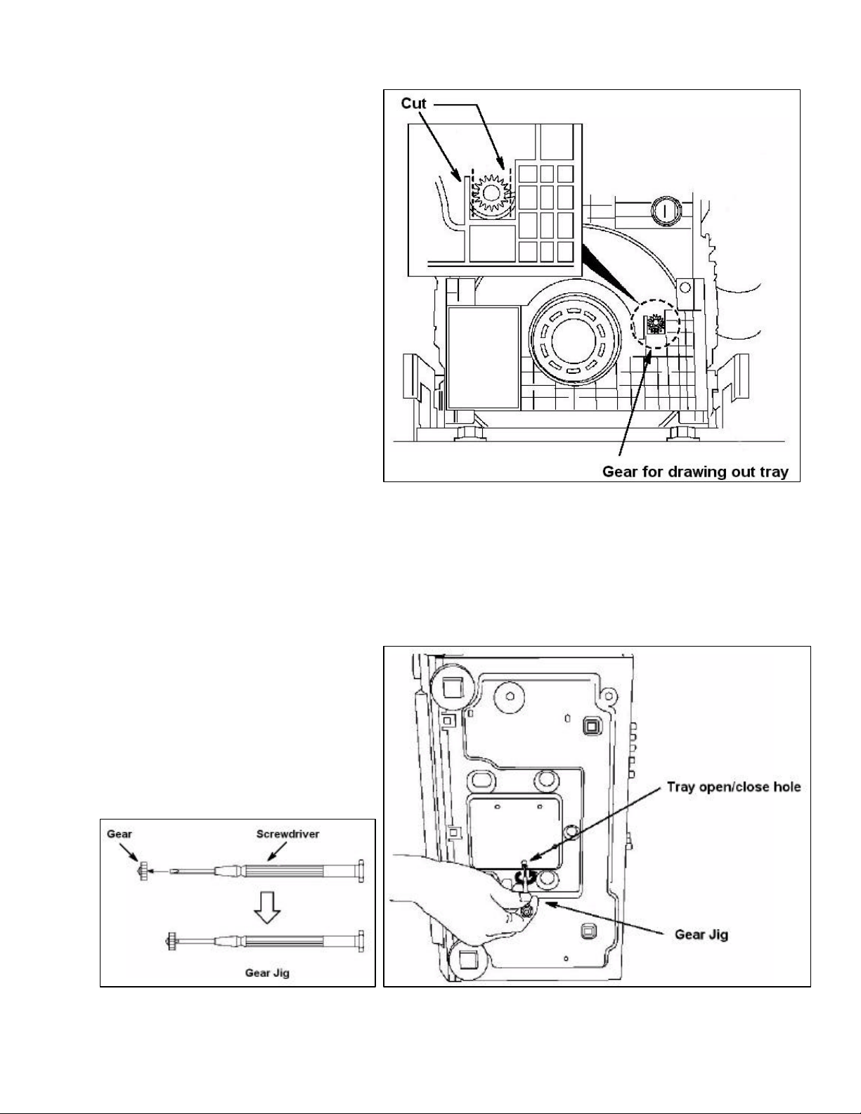
However, if the loading mecha has no power to
it or the unit is just dead, there is a manual
override in the form of an extra gear used to
release the tray. As shown in the top drawing
to the right, the gear is located on the top of the
mechanism just above the disc stabilizer. Simply
break the gear off of the Clamper unit and push it
onto the front end of a small screwdriver.
Next turn the unit on its side and insert the Gear Jig
into the hole in the bottom of the unit as shown in the
drawing at the bottom right. Turn the gear jig
counter-clockwise to eject the tray. The amount of
turns depends on how far away from home position the
traverse assembly is. Remember in the design
of the DVD-RV31 the traverse and loading use
the same motor.
Release the tray so that the Tray Front is far
enough out that it can be pull up and off of the
tray. Then turn the Gear Jig in the clockwise
direction to load the tray back into the
mechanism. Now remove the Top Cover,
followed by the Front Panel so than the
mechanism can be removed.
9
Page 10
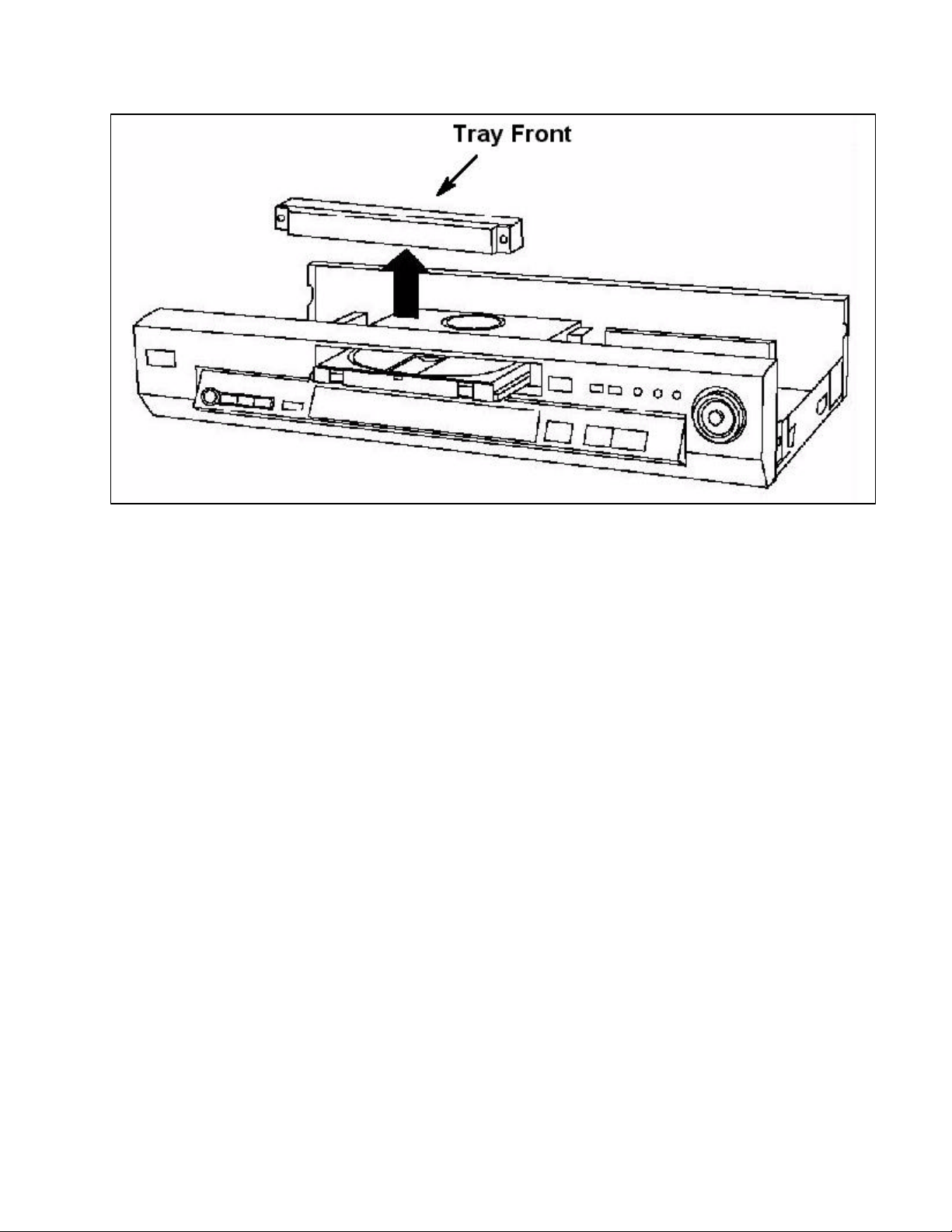
Illustration of Tray Front being removed from the tray in an upward direction
10
Page 11
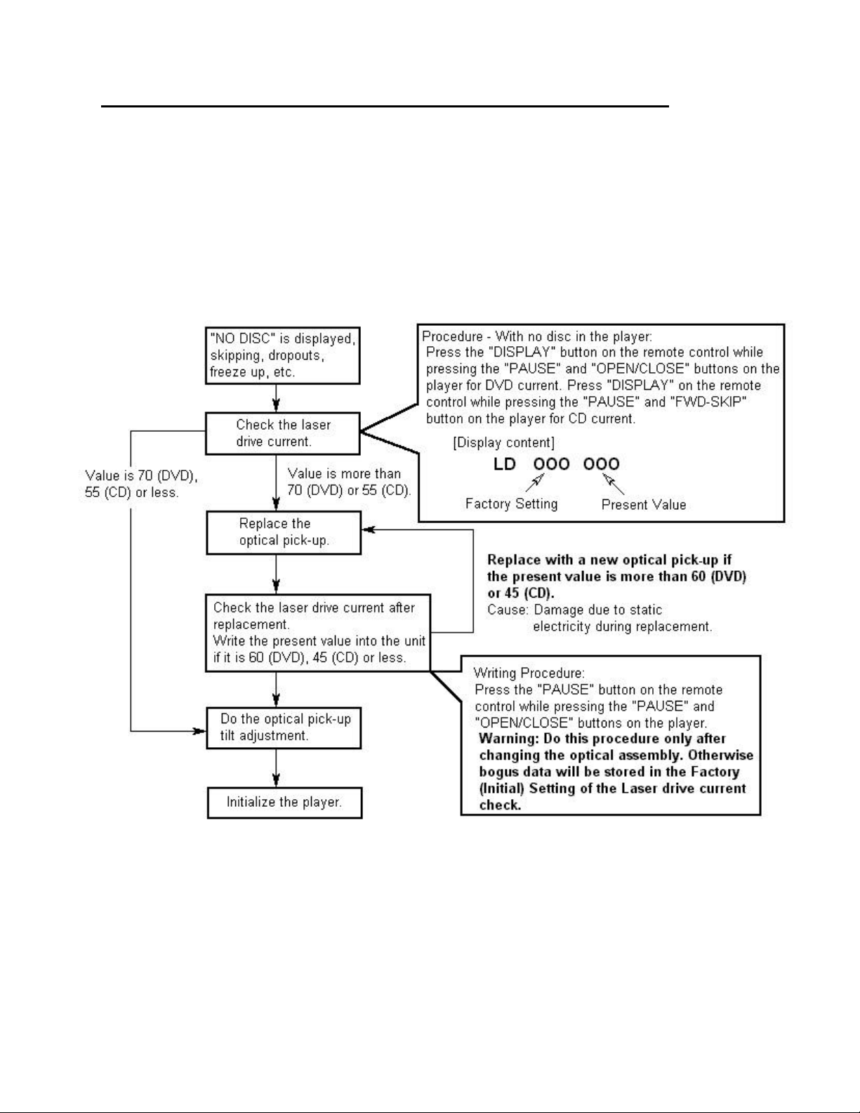
OPTICAL PICK-UP SELF-DIAGNOSIS AND REPLACEMENT PROCEDURE
The optical pickup self -diagnosis function and tilt adjustment check have been included in this unit. When
repairing, use the following procedure for effective self -diagnosis and tilt adjustment. Be sure to use the selfdiagnosis function before replacing the optical pick-up when "NO DISC" is displayed. As a guideline, you
should replace the optical pickup when the value of the laser drive current is more than 55(CD) or 70(DVD).
Note:
Checking the laser drive current should be done within the first three minutes of turn on, with no disc loaded in
the unit to ensure an accurate reading.
11
Page 12

DISC STABILIZER
To deal with the problem of warped discs, which
could be unplayable or cause noise, conventional
DVD players have depended on servo technology.
However, if a disc is extremely warped or has a large
localized warp, there is a limit to a servo’s
effectiveness. Panasonic’s newly developed Disc
Stabilizer applies corrective pressure at the outer edge
of the DVD to minimize overall warpage and evenly
distribute localized warpage, while suppressing
vibration. As a result, DVD playability is strongly
improved. A strong yet lightweight honeycomb
structure of glass reinforced PPE (polyphenylene
ether) manufactured to a tight tolerance (+/- 50
microns or less) is key to the stabilizer’s success.
Upper and lower damper sheets further improve
vibration and noise suppression performance. The
stabilizer contacts the DVD only at the disc’s
innermost and outermost non-signal peripheries, using
nonwoven material to prevent damage to the surface.
Problems where a disc cannot be played due to a high laser current or jitter rate, can possibly be fixed by performing the
Tilt Adjustment. Do this adjustment before changing the Optical Pick -Up Assembly.
Optical Pick-Up Tilt Adjustme nt
Measurement Point Adjustment Point Mode Disc
Main UnitMain Unit
Service DisplayService Display
Measuring Equipment/Tools Adjustment Value
Hex Wrench (Part Number: SZZP1101C)
Screw Lock (Part Number: RZZ0L01)
1. Power on DVD player and load either test disc
DVDT-S15 or DVDT-S01.
2. Place the unit in the Jitter Display Service Jitter Display Service
ModeMode by simultaneously pressing “PAUSE”“PAUSE” +
“OPEN/CLOSE”“OPEN/CLOSE” on the player with the
number “5”“5” button on the remote. (On the FL
Display will appear “J_xxx_yyy_zz”“J_xxx_yyy_zz”)
Note: The “xxx” represents jitter value of the
disc. The “yyy” and “zz” have nothing
to do with the jitter value, they represent
the error counter and focus drive value
respectively.
Tangential Adj. Screw
Tilt Adj. Screws
T01 (Inner Periphery) Play
T43 (Outer Periphery) Play
DVDT-S15 or DVDT-S01
Adjust to the Minimum Jitter ValueAdjust to the Minimum Jitter Value
12
Page 13

Tangential
Tilt Adjustment Screw 2
Tilt Adjustment Screw 1
3. Play “Title 1”“Title 1” of the test disc while using the
Hex Wrench (SZZP1101C) to adjust the
Tangential ScrewTangential Screw from the bottom of the player.
Adjustment
Adjust for minimum Jitter Value on the display.
4. Next play “Title 43”“Title 43” of the test disc and
manipulate the Tilt Adjustment Screw 1Tilt Adjustment Screw 1
for minimum Jitter Value.
5. Then continue playback of “Title 43”“Title 43”
while adjusting Tilt Adjustment Screw 2Tilt Adjustment Screw 2
for minimum Jitter.
6. Repeat adjusting Tilt Adj. Screws 1 & 2
alternately, two or three times.
7. Check condition of the player. Play the
disc to make sure there is no picture
degradation in the inner, middle and
outer peripheries and no audio skipping.
8. When Best possible Jitter ValueJitter Value is
achieved, turn the unit off and
unplug it. Disassemble the player so
that the Traverse Unit is removed.
(Remove top cover, tray front, front panel, mecha and traverse unit in this sequence)
9. Lay traverse unit upside down, and lock all
three adjustment screws in place using screw
lock (part number: RZZ0L01)
10. Reassemble the player. (Reassemble traverse
unit, mecha, front panel, tray front and top
cover in this sequence)
11. Enter JitterJitter Display Service ModeDisplay Service Mode once more
and playback a disc to make sure value is still
good.
12. Initialize the Player by simultaneously
pressing “PAUSE”“PAUSE” + “OPEN/CLOS“OPEN/CLOS E”E” +
““BACKBACK--SKIPSKIP”” on the player.
The procedure is now complete.
Notes:
• Adjustment is generally unnecessary after
replacing other parts of the Traverse Unit.
However, adjust if there is a noticeable
degradation in picture quality.
• Optical adjustment cannot be made inside the
Optical Pick-Up. Adjustment is generally
unnecessary after replacing the Traverse Unit.
Screw
13
Page 14

DVD PRIMARY POWER SUPPLY CIRCUIT
This is the primary circuit of the Switching Mode Power Supply found in the model DVD-RV31. The entire
primary circuit will be active as long as it is plugged into 120Vac. If you are troubleshooting in this area of the
power supply an Isolation Transformer must be used.
Current enters the circuit through fuse F1001 and then passes and goes through the surge suppressors
(D1001 and D1002) and the line filter (L1001, C1001 and C1002). C1003 and C1005 are used to isolate the
potential difference between the hot and cold grounds. The AC voltage is rectified and filtered by the diodebridge D1011 and capacitor C1014. This DC voltage is applied to the collector of Q1021, the switching
transistor, though the primary winding of T1021 (Pins 3 and 5).
Start Up
A small bleed current through R1041 and R1042 to the base of Q1021 accomplishes start up. A voltage drop
high enough to bias the switching transistor on will appear at the base. This turns Q1021 on slightly, but is not
strong enough to keep it on permanently.
The voltage on the collector will begin to fall as current through the primary winding of T1021 and the collector
emitter junction of Q1021 to ground increases. The current flowing through the primary winding will induce
currents into all of the secondaries of the transformer, including the one at pins 8 and 9. This current will flow
through coil LR1041 and be rectified to a DC voltage by D1041 and is applied to the base of Q1021. This path
will provide enough current to turn Q1021 on fully. So it is important to remember that there are two start -up
paths in this power supply, one through R1041 and R1042, and the other through LR1041, D1041 and R1043.
Regulation
This switch mode power supply monitors the Non-Switched +5V line for regulation process. The major
components in the feedback circuit are IC1101, Q1051 and Q1052. Resistors R01, R02 and R03 on the
secondary side form a voltage divider network. When the 5V line increases high enough to allow the voltage
drop across R03 to turn on the zener diode inside IC1101, current will flow through this zener diode and the
LED inside Q1051. The B+ supply for the LED inside Q1051 is the cathode of D11, the 5V line.
14
Page 15

DVD SECONDARY POWER SUPPLY CIRCUIT
When the LED inside Q1051 is on it emits light, which is directed at the base of the phototransistor. B+ is
applied to the collector of the phototransistor inside Q1051 from pin 8 of T1021, through C1051 and D1051.
With light applied to the base of the phototransistor it turns on and a current path is formed from pin 8 of the
transformer to Q1051 and on through R1051 and D1052 to the base of Q1052. This turns Q1052 on which will
draw current away from the base of the switching transistor Q1021, turning it off.
This circuit works just the opposite way when the 5V line is low. The voltage drop across R03 will be less, so
IC1101 will be off, as will Q1051 and Q1052. The switching transistor Q1021 will then stay on.
Protection
If there is an open in the regulation loop, the zener diodes on the secondary side of the power supply will short
which will cause Q1021 to open eventually. If one of the semiconductors (IC1101, Q1051 and Q1052) in the
regulation circuit were to short the power supply would not oscillate.
Over voltage protection is provided by zener diode D1053. If the pulse at pin 8 of T1021 increases in amplitude
it will eventually reach a point where it biases D1053 on. The positive portion of the pulse will be applied to the
base of Q1052 via R1054, turning the transistor on. When Q1052 is on, base current for Q1021 will be reduced
and it will turn off.
15
Page 16

Secondary Voltages
There are two classifications of secondary voltages from
this power supply, non-switched and switched voltages.
See chart at left. The non-switched voltages will be there
whenever the unit is plugged in. The switched voltages
appear only when the unit is turned on.
The non-switched voltages FLH+, FLH- and FL –30.8V
are all used for the fluorescent display. The FL –30.8V
goes to the Operation Microprocessor IC6001 as the B+
for the segment drive.
The non-switched +5V line is the VDD source at pin 8 of
IC6001 the Operation Micro. This micro monitors the key
matrix and the remote IR sensor for commands from the
user. It also controls the fluorescent display.
The non-switched +/-10V and +/-12V are used to power
the audio and video output sections.
The Switched D +5V line is used as the B+ source for IC6201 the Main CPU. This voltage is regulated down to
3.3Vdc by IC6251 and the 3.3V is applied to VDD of IC6201, pin 83. IC6201 controls the servo, audio/video
decoding and masters the bus line between it and the sub micro IC6001.
The M +9V line is used to power the two motors on the mechanism.
The Switched voltages are controlled by the status of the Power On line. This is controlled by pin 40 of IC6001
the Operation Micro. When the unit is off, this line will be low and IC1151, QR1115 and IC1125 will all be off.
When the power button is pressed on the DVD Player, the Power On line will go high and allow the switched
voltages to be developed.
Both switched +5V lines and the +2.5V line are used as the source B+’s for the servo and audio/video
decoding circ uits.
16
Page 17

Optical Assembly
The optical pickup assembly in
the DVD-RV31
uses two lasers,
one for CD’s and
the other for
DVD’s. This is a
departure from
previous years.
Before all home
DVD Players had
a holographic
objective lens and
one laser that
operated at two
different
wavelengths and
power levels
depending on the
type of disc being
played. Only older
portable units
used dual laser
optics for the
reason of space
saving.
For 2001, Panasonic is incorporating MP3 audio file playback from CD-R and CD-RW discs on most of its DVD
Players. The single laser, dual wavelength optical pick-ups with the holographic objective lens are not able to
read these types of discs. A dual laser pick-up is able to read CD-R’s and CD-RW’s though.
Optical Pick-Up Assembly Break Down
CD Module: Contains semiconductor laser and light -receiving elements in one package.
Light wavelength is 790nm.
DVD Module: Contains semiconductor laser and light -receiving elements in one package.
Light wavelength is 658nm.
Dichroic Prism: A prism that will only pass light of a specific wavelength and reflect all others. In this case it
will only pass the CD wavelength.
Collimator Lens: Is used to prevent the laser beam light from scattering.
Mirror: Is used to reflect the path of the light by 90°.
Objective Lens: Is used to precisely focus the laser beam onto the track of the disc to read the data off of it.
When a disc is loaded into the player, both lasers will turn on sequentially. The type of disc will be determined
by which laser can properly focus on the track of the disc. If the door is closed without a disc being loaded, the
modules will receive no light back and “NO DISC” will be displayed.
17
Page 18

LASER POWER CONTROL CIRCUIT
The diagram above shows the two laser control circuits used in the DVD-RV31. Pins 3 and 5 of the Front end
Processor are the output pins that control the two lasers. 5Vdc will appear on both of these pins when the
lasers are off. The procedure for the DVD laser to turn on is as follows: pin 3 of IC5201 will drop to a lower DC
voltage. This is applied directly to the base of Q5211, turning it on. Q5211 is a switch, which allows current to
flow to the Laser Diode when turned on.
With the laser now on, we use the feedback circuit into pin 2 of IC5201 to regulate its power level. The laser
emits light, which is picked up by the feedback photo diode situated just below the laser diode in the picture
above. The current flowing through the photo diode causes a voltage drop to occur across the terminal of the
potentiometer. This DC voltage is applied to the comparator amp inside the Front End Processor via pin 2.
Here it compared to an internal reference voltage, which regulates the DC level at pin 3.
The potentiometer(s) is set at the factory to allow maximum efficiency from the laser. It is not an
adjustment to be done out in the field.
A used laser that is weak will require more current to properly read the data off of a disc. In that situation the
comparator amp will cause pin 3 to drop to a lower DC voltage than normal, so as to turn Q5211 on harder and
allow more current to flow to the laser. In this situation the laser diode is more prone to total failure since it is
running hotter.
The laser control circuit for the CD laser works exactly the same.
18
Page 19

FOCUS SERVO CIRCUIT
Upon initial start -up two things must be determined, is a disc present and what type of disc is present. Both
lasers are turned on sequentially and a disc is determined to be loaded in the unit if there is current flow from
any of the photodiodes. Once the Main CPU knows there is a disc present, it informs the Digital Servo
Processor IC2001 to start the focus process. The servo processor sends out a ramp signal to IC2501 the Coil
Driver to raise the lens. The amount of reflected light to each set of the photodiodes is calculated to determine
the type of disc.
Once the disc type has been determined, only one laser module will be working and the servo circuit will be set
to the proper power level. The servo circuit operates similarly to any digital servo CD player. The Focus Error
signal is converted to 8 bit data by the Analog to Digital Converter. The 8 bit data is applied to the Servo
Processor, which sends out a digital correction pulse. The correction pulse is transmitted as PWM out pin 5 of
IC2001 and converted to analog by a low-pass filter. The DC level is applied to IC2501 to adjust the current
level of the focus coil. Dual layer discs are processed the same way except for a change in the focus point.
The unit will change focus points when either a command from the CPU interface is received or when the end
of the first layer is reached.
19
Page 20

TRACKING SERVO CIRCUIT
After Focus has been detected the spindle motor is turned on and the disc is spinning. The tracking circuit is
turned on by a command from the microprocessor to the servo processor. The objective of the tracking servo
is to maintain the laser light directly on the track of the disc.
The tracking error is determined by the phase difference of all four photodiodes for a DVD and the offset of the
balance of the Diagonal pairs in CD mode. The error signal output pin 13 of IC5201 is converted to digital by
the A/D Converter and applied to the Digital Servo Processor inside IC2001. The correction signal for tracking
is sent out to the Coil Driver as PWM, through a low pass filter and the lens is moved in or out by the DC
current flow from either pins 13 or 14. The Objective Lens can only be moved in or out about ten tracks by the
Tracking Servo, so the Servo Processor also monitors the tracking error signal for information on when to
move the traverse motor.
20
Page 21

TE Signal
TRAVERSE SERVO AND LOADING MOTOR CIRCUIT
Traverse Servo
The Traverse Servo takes its input from two sources. When the Tracking Error signal is too high the traverse
motor mus t move to correct the position of the optical assembly. This is called the “Kick Pulse”. Remember the
Tracking circuit can only move the Objective Lens a small distance on its own. The traverse motor will move
the whole optical assembly in or out, up to ten tracks in normal play mode. When the Kick Pulse is received,
IC2001 outputs corrective PWM out pin 51. This goes through a low pass filter (not shown) and changes the
DC voltage level at pin 26 of IC2501 the Motor Driver. This DC level change causes the top comparator amp to
output a corrective voltage through the switch to the Level Shift circuit. Here the DC voltage is transformed into
a current and flows from either pin 15 or pin 16 to turn the motor so the Optical Assembly moves in or out.
The other input to the Traverse Servo is from IC6001
the Sub CPU. When a user command is entered to
change the track or chapter of the disc, it is entered
into IC6001 via either the remote control IR sensor or
a button-push in the key matrix. This command to
change the position of the Optical Assembly is sent to
IC2001 via the data bus between the Sub CPU and
the Main CPU IC6201 and on from there through the
bus to the Digital Servo Processor.
Loading Motor
In the design of the mechanism for the DVD-RV31,
the same motor used for moving the Traverse Assy in
and out is also used for loading the disc. This is
accomplished through the use of a “Chuck”, which
either connects the Loading Gears or the Traverse
Optical Assy Drive Rack to the one motor. The
Kick Pulse
21
Page 22

position of the Chuck is detected by IC6001 and IC2001, by the status of SW2501 the Tray In SW (Home
Position SW). The Traverse Servo circuit will drive the Optical Assy past Home Position until the OPU Drive
Rack disengages from the motor’s drive gears. The OPU being pus hed in past Home Position, moves the
Chuck and connects the Tray Loading gears to the motor.
Pins 27 and 28 of IC6001 are
the output pins that drive the
Loading motor in or out.
Approximately 1.6Vdc will
normally appear on these
pins when the mecha is
sitting in the loaded position.
When the Sub CPU receives
a user command to eject the
tray pin 47 will drop low to
change the position of the
internal switch inside the
Motor Driver IC. Pins 27 and
28 of IC6001 will increase
their DC level, which
increases the DC voltage at
pin 24 of IC2501. This DC
level change causes the
bottom comparator amp to
output a voltage through the
switch to the Level Shift
circuit, and a current flows
through the loading motor to
eject the tray. The Loading Motor ceases
action when the Tray Out SW closes (Not
shown). The Tray Out SW is located on the
front right side of the mechanism.
To load the tray, Sub Micro pin 47 stays low,
and pins 27 & 28 drop to a lower voltage.
This puts a lower DC voltage at pin 24 of the
Motor Driver IC, which causes the bottom
comparator amp to output a voltage at the
opposite polarity. This is transferred through
the switch to the Level Shift circuit and the
current flows through the loading motor in the
opposite direction to load the tray.
Once the tray is fully loaded, the Chuck
pushes the OPU Drive Rack to make
connection with the motor. The Traverse
Motor drives the Optical Assy out enough to
open SW2501 to let IC2001 and IC6001
know that the mecha & the circuit are in
Traverse mode now. Pin 47 of the Sub CPU
will go high to change the position of the
internal switch of IC2501. Then the Pick-Up
is moved back in to Home Position and the
laser turns on. If a disc is detected the Focus
Servo process starts.
22
Page 23

SPINDLE SERVO CIRCUIT
The spindle servo has two modes of operation DVD mode and CD mode.
DVD Mode
In DVD mode, the PLL circuit in the Digital Servo Processor (IC2001) decodes the RF data. The objective is to
output the data at a Constant Linear Velocity (CLV). The servo goes through three stages: Rough servo, Fine
servo and CLV servo. Rough servo is approximately 1000 rpm; the S/S line turns on and approx. 3.2Vdc is
output pin 56 of IC2001 to start the motor. When the disc is not spinning this pin will have 0Vdc on it.
Fine servo is a frame rate of 18145 frames per second; pin 52 the SPDRV of IC2001 pulses to speed up or
slow down the motor comparing the sync rate to the reference clock. CLV servo is 13.5 Mbits per second, the
SPDRV line pulses to speed up or slow down the motor comparing the data rate to the reference clock to
produce the proper data rate. If the speed varies, the RF data provides the feedback path. Current deviation
feedback is provided at pin 6 of IC2501 as a fine adjustment to the Spindle Motor Control. Remember the disc
will spin faster when the center is being read compared to the outside edge, so the DC level at pin 23 of
IC2501 will be higher approx. 2.1Vdc in the center of the disc compared to approx. 1.9Vdc at the edge.
IC2001 also monitors the output of the PLL circuit to determine if there is jitter present in the picture. Picture
Jitter can be determined by monitoring the Horizontal Sync frequency. Jitter can occur because the spindle
servo will consistently overshoot the CLV speed then undershoot the CLV speed. The constant speed
adjustment may not cause a symptom on screen, but forward and reverse search may be more difficult. This
circuit monitors the sync frequency and momentarily delays the correction signal to prevent over or under
shoot.
23
Page 24

CD Mode
In CD mode, the disc spins at about ½ as fast as in DVD mode other than that the PLL circuit in the Digital
Servo Processor (IC2001) works the same. The PLL circuit decodes the RF data. The objective is to output the
data at a Constant Linear Velocity (CLV). The servo goes through three stages, Rough servo, Fine servo and
CLV servo. Rough servo is approximately 500 rpm; the S/S line turns on to start the motor (3.2Vdc). Fine servo
is a frame rate of 7350 frames per second; the SPDRV line pulses to speed up or slow the motor comparing
the sync rate to the reference clock. CLV servo is 4.32 Mbits per second, the SPDRV line pulses to speed up
or slow down the motor comparing the data rate to the reference clock. If the speed varies, the RF data
provides the feedback path. Current deviation feedback is provided at pin 6 of IC2501 as a fine adjustment to
the Spindle Motor Control.
When decoding MP3’s off of a CD-R or CD-RW, the Spindle Servo will be in CD mode.
24
Page 25

VIDEO BLOCK DIAGRAM
The Digital Servo Controller IC2001 receives as an input the RF Envelop signal. IC2001 is the chip that
controls the focus and tracking coils, and the traverse and spindle motors to maintain a stable RF Envelop at
approximately 1Vp-p. The DSC chip converts the RF signal into digital 4 bit data. This digital data is then sent
to the Optical Disc Controller IC7001, which performs error detection and correction on the data. The data that
is recorded on the disc is not in its proper sequence. This is a process called interleaving, which is used to
prevent large errors. IC7001 performs the De-Interleave process to put the data back into it’s proper sequence.
Also the region code of the disc is compared to that of the player. They must match for the disc to playback in
the player. The output of the ODC is the 8-bit MPEG 2 transport stream.
Remember the MPEG 2 transport stream contains both video and audio information at this point. The MPEG 2
data is input to the A/V Decoder, where the audio information will be striped away from the video dat a.
Decompression of the video data is performed by IC3001. Due to the large amounts of data, the A/V Decoder
uses IC3061 the 16M SDRAM as a storage location during the decompression process. Independent Luma,
Chroma, Cr and Cb siganls are output from the A/V Decoder. The macro vision process is also performed in
IC3001.
The Y and C signals are output the A/V Decoder from pins 134 and 119 respectively. They pass through two
buffer amps before being applied to the Video Driver IC3501. The Cb and Cr color signals are output the A/V
decoder and are passed straight to the Video Driver.
Inside IC3501 the Y and C signals are mixed together to form the composite video output. The Y and C signals
are also output as separate signals to be used for the S-Video jack. The Y output, at pin 19 of the Video Driver
is the source for the Y Component output too. The Cb and Cr signals are used for the component Pb and Pr
signals. All video signals are amplified and impedance matched by IC3501.
25
Page 26

AUDIO BLOCK DIAGRAM
The signal path from the Pick-Up to IC7001 is the same process as the video block diagram. The MPEG 2
transport stream, which contains both audio and video information at this point is the input to the A/V Decoder
IC3001. The audio signal is separated from the rest of the MPEG 2 data and output from the A/V Decoder
digitally at both pins 92 and 85.
The DVD-RV31 does not have an internal Dolby Digital (AC-3) and/or DTS decoder. If the player is connected
to an external Dolby Digital (AC-3) and/or DTS decoder, it mus t be connected to the Digital Audio Optical
output in order to obtain the 5.1 discrete channels of audio.
If the audio is being output to the TV’s stereo speakers, the mixed left and right outputs are the path used. In
this situation however, Virtual Surround Sound audio can be heard from the TV. IC3001 in the DVD-RV31
contains the VSS circuit, which simulates surround sound using just the two stereo speakers of the TV.
The audio data in a digital form is output pin 92 of IC3001 and converted to two analog channels by IC4201 the
DAC. The left and right audio signals are buffer amped by IC4301 and pass by a muting circuit before they
reach the output jacks. The muting circuit consists of transistors Q4410 and Q4419, which basically ground the
left and right audio signals when pin 64 of the micro goes high.
In CD audio mode, Eight to Fourteen Bit Modulation (EFM) data is output from the Optical Disc Controller after
error correction and the de-interleave process has been performed. The A/V Decoder converts the EFM to
16 bit left and right audio data, which is converted to left and right audio by IC4201 the DAC. Pulse Coded
Modulation (PCM) is output pin 85 of IC3001 to the digital optical output.
In MP3 mode, the 8 bit MPEG 1 transport stream is input to the A/V Decoder IC3001. Audio data in digital form
is output from IC3001 at both pins 92 and 85. MPEG 1 Layer 3 data is output pin 85 directly to the Digital
Optical Output. This can be output as bitstream or PCM.
Digital audio is also output pin 92 of IC3001 to be converted to left and right audio signals by the DAC IC4201.
26
Page 27

FLASH ROM UPGRADES
Older DVD model Flash ROM upgrades
were accomplished by using an Flash ROM
Burner that was available from Panasonic.
For 5th generation DVD models (2001 year)
a new recovery disc is provided as a service
tool. There are two conditions when the
recovery disc should be used.
1. Whenever the Flash ROM or EEPROM
IC has been replaced on the DVD
Module board.
2. Whenever the firmware version of the
DVD Player needs to be upgraded.
Tools needed:
Recovery Disc (RFKZD5TR001)
TV Monitor
Recovery Disc part # RFKZD5TR001
Warning!!!! Do not turn off the power to the unit when the recovery disc is being read or during the
recovery or update process. The error code F893 will appear indicating the Flash ROM IC has become
corrupted and will have to be replaced.
Firmware Version Check
Confirm the firmware version of the DVD player
by holding down the “Pause” and “Open/Close”
buttons on the unit, then press the “Number 7”
button on the remote control. The firmware
version will appear on the Fluorescent display.
Several firmware versions are contained on this
disc (see table at right). The appropriate one
will be downloaded depending on the results of
the model and firmware check.
The firmware versions on this disc are up to
date as of June 2001. If the unit has a newer
firmware version than that provided on the disc,
it will not be changed.
The firmware version should be check before
and after the update to make sure the proces s
was successful.
27
Page 28

Recovery Process
To use the recovery disc after the Flash ROM or EEPROM IC has been replaced use the procedure just
below.
1. Insert recovery disc into the player.
2. The player reads the disc and the recovery process is automatically ex ecuted.
3. The TV monitor display goes blank and the DVD player momentarily powers off then back on.
4. The player reads the disc again and displays “COMPLETED” on the monitor.
5. Eject the disc and power the unit off.
Note: If the new Flash ROM IC contains an older firmware version, the firmware update process will continue.
Firmware Update : (OSD Option 1)
Use if the player has an earlier firmware version or for strange types of problems.
1. Insert recovery disc into the player.
2. The player reads the disc and the recovery disc checks the players existing firmware version.
3. If the players firmware version is earlier than that on the disc, the TV monitor will display:
“This player needs the up-date. Do you want to up-date? “ [Yes] [No]
4. Select “YES” and press the Enter button.
5. The TV monitor displays: “Disc check in process” (approx. 5 Seconds)
6. The TV monitor displays: “Update in process….Please wait a moment” (approx. 1 minute)
7. The TV monitor goes blank, the player powers off then on again and reads the disc one more time.
8. The TV monitor displays: “Completed. Please eject the disc.”
9. Eject the disc and power the unit off.
Note: Depending on the model and Flash ROM IC capacity (4Mb – 32Mb), the update process time may vary
between 1 to 4 minutes.
Firmware Update : (OSD Option 2)
If the player firmware version is equal to or newer than the disc version, no update is done.
1. Insert recovery disc into the player.
2. The player reads the disc and the recovery disc checks the players existing firmware ve rsion.
3. Recovery process is executed and the firmware is not changed.
4. The TV monitor will display: “Completed. Please eject the disc.”
5. Eject the disc and power the unit off.
28
Page 29

SERVICE POSITIONS
Terminal PCB
Mother PCB
Module PCB
The service position shown in the top picture should
be used when troubleshooting on the Module or
Terminal PCBs or when checking the mechanism. The
service position pictured in the bottom left should be
used when making repairs on the Mother PCB.
Only two extension cables are needed for either
service position. The part numbers for the cable are
listed in the chart at right.
Mechanism Unit Mother PCB
Module PCB
Cable Part # Pins Model
1 JGS0098 26 DVD-RV41
1 JGS0116 22 DVD-RV31
2 JGS0116 22 Both
1
2
Only
Only
29
Page 30

SERVICE TOOLS AND EQUIPMENT
Application Name P art Number
DVD Test Disc DVDT-S15 or DVDT-S01 Tilt
Adjustment
Others
Confirmation
Hex Wrench SZZP1101C
Extension Cable (Module PCB to Mother PCB) JGS0098 (DVD-RV41 Only) Inspection
Extension Cable (Module PCB to Mother PCB)
(Order 2 cables for RV31/Order 1 cable for RV41)
Screw Lock RZZ0L01
Grease RFKXGAK152
Oil RFKXGA1280 or JZS0648
CD Test Disc PVCD-K06 or any other
VCD Test Disc PVCD-K06 or any other
JGS0116
Commercially available disc
Commercially available disc
30
Page 31

Service Mode Table
DVD Laser Current
CD Laser Current
ITEM PLAYER
BUTTONS
Jitter Check Pause +
Error Code
Check
Write Setting of
Laser Current
DVD Laser
Drive Current
CD Laser
Drive Current
Open/Close
Pause +
Open/Close
Pause +
Open/Close
Pause +
Open/Close
Pause +
Fwd -Skip
REMOTE
BUTTONS
5 Play Jitter rate is measured and displayed.
0 ***** The latest error code stored in the EEPROM is
Pause Stop Initial current value for both the DVD laser and
Display Stop DVD laser current is measured and the result is
Display Stop CD laser current is measured and the result is
PLAYER
MODE
FUNCTION DISPLAY CANCEL
Measurement is repeatedly done in the cycle of
one second. Read error counter starts from zero
upon mode setting. When target block data failed
to be read out, the counter advances by one
increment. When the failure is caused by minor
error, it may be corrected when retried to enable
successful reading. In this case, the error persists
even after retry; the counter may jump by two or
more.
displayed.
See chart on page 34.
Up to 20 Errors can be stored and viewed by using
the arrow up/down buttons on the remote control.
the CD laser are separately saved in the
EEPROM.
No discs in the player.
displayed together with the initial value stored in
the EEPROM.
After the measurement, DVD laser emission is
kept on. It is turned off when the Power button is
turned off. (It is also turned off when the primary
power is switched off.)
No discs in the player.
displayed together with the initial value stored in
the EEPROM.
After the measurement, CD laser emission is kept
on. It is turned off when the Power button is
turned off. (It is also turned off when the primary
power is switched off.)
No discs in the player.
J _xxx_yyy_zz
Focus Drive Value
Read Error Counter
Jitter Rate
Jitter Check Mode
Jitter rate is shown in decimal notation to one
place of decimal. Focus drive value is shown in
hexadecimal notation.
Error code (Play_err) is expressed in the following
condition:
Error code = 0 x DAXX is expressed: à nn UXX
Error code = 0 x DBXX is expressed: à nn HXX
Error code = 0 x DXXX is expressed: à nn FXXX
Error code = 0 x 0000 is expressed: à nn F--* “nn” denotes the serial number of history.
LD0_034_028
The value denotes the current in decimal notation.
The above example shows the initial current is 34mA
for the DVD laser and 28mA for the CD when the
lasers are switched on.
CD Laser current level
DVD Laser current level
Laser Current level mode
LD0_032_034
The value denotes the current in decimal notation.
The above example shows the initial current is 32mA
and the measured value is 34mA.
LDC_026_028
Measured current level
Initial current in EEPROM
level mode
Measured current level
Initial current in EEPROM
The value denotes the current in decimal notation.
The above example shows the initial current is 26mA
and the measured value is 28mA.
level mode
METHOD
Stop or
Open/Close
Cancelled
automatically
after 5 seconds.
Cancelled
automatically
after 5 seconds.
Cancelled
automatically
after 5 seconds.
Cancelled
automatically
after 5 seconds.
31
Page 32

ITEM PLAYER
ADSC internal RAM data
System controller release number
r model number
BUTTONS
ADSC Internal
RAM Data Check
Servo Process
Display
Version Display Pause +
Lighting of
Display Tube
Deal er’s Lock Stop Power Stop The lock is switched On or Off.
Initialization Pause +
Region Display Pause +
Pause +
Open/Close
Pause +
Fwd -Skip
Open/Close
Pause +
Open/Close
Back-Skip +
Open/Close
Open/Close
REMOTE
BUTTONS
Return ***** ADSC internal RAM data is read out and
7 Stop The servo process from Stop to Access is
7 Stop Flash ROM version displayed.
9 ***** Lights up all segments of the display tube. Turn off the
Stop User settings are cancelled and player is initialized
6 Stop Displays Region information.
PLAYER
MODE
FUNCTION DISPLAY CANCEL
displayed.
Change the address with the Cancel button to
show the data for 14 addresses.
See chart on page 36.
displayed.
When the dealer’s lock is On, it prohibits
switching off the secondary power and opening
the tray.
The status of the lock is stored in the EEPROM.
to factory settings.
Buttons must be held for 3 or more seconds.
A_4B4_018D
The value is shown in hexadecimal notation. The
above example shows the data in ADSC address
DFAh is 6901h.
See page 35.
RAM data for specified address
Address
check mode
Srrr_xyzzz
“LOCKED” appears on the display when the dealer’s
lock is turned on, or when either the Power or
Open/Close buttons are pressed when the lock is On.
“UNLOCKED” appears on the display when the
dealer’s lock is turned Off.
“INITIALIZED”
x__yy__zzz
System controlle
System controller generation
Panel controller release number
Panel controller model number
N: NTSC / 6: PAL60
N: noPAL / P: PAL
Region Number
METHOD
Stop or
Open/Close
Turn off the
secondary
power
Cancelled
automatically
after 5 seconds.
secondary
power
Repeat the
same
operation.
Cancelled
automatically
after 5 seconds.
32
Page 33

LASER AND SPINDLE OPERATION TIMERS
ITEM PLAYER
BUTTONS
Timer 1 Check
DVD & CD
Lasers
Timer 1 Reset
DVD & CD
Lasers
Timer 2 Check
Spindle Motor
Timer 2 Reset
Spindle Motor
Pause +
Fwd-Skip
Stop +
Fwd-Skip
Pause +
Fwd-Skip
Stop +
Fwd-Skip
REMOTE
BUTTONS
PLAYER
MODE
FUNCTION DISPLAY CANCEL
5 Stop Laser operation timer.
Operation time is measured separately for
the DV D laser and the CD laser.
5 While
Displaying
Timer 1
Data
Laser operation timer.
Operation time of both the DVD and CD
lasers are reset all at once.
Should only be done when laser is changed.
6 Stop Spindle motor operation timer. T2_1234
6 While
Displaying
Timer 2
Spindle motor operation timer will be reset.
Should only be done when spindle motor is
changed.
Data
METHOD
T1_1234_5678
Shown on the display is the total operation times
for the DVD and CD lasers. DVD laser time the
first set of numbers from the left and CD is the
Cancelled
automatically
after
5 seconds.
numbers to the right.
Time is shown in 4 digits of decimal notation in
a unit of 10 hours. (“0000” will follow “9999”)
T1_0000_0000 Cancelled
automatically
after
5 seconds.
Cancelled
Time is shown in 4 digits of decimal notation in
a unit of 10 hours. (“0000” will follow “9999”)
automatically
after
5 seconds.
T2_0000 Cancelled
automatically
after
5 seconds.
33
Page 34

ERROR CODES
ERROR CODE EXPLANATION CHECK POINT
CHECK THE DISC Focus Trouble IC2001, IC5201, pickup
U11 Focus Trouble IC2001, IC5201, pickup
H01 Tray loading trouble IC2001, Loading motor, defective
H02 Disc motor Trouble Spindle motor, IC2501, IC2001
H03 Traverse Trouble Traverse motor, IC2001
H04 Tracking Servo Trouble IC2001, IC2501, IC5201, pickup
H05 Seek trouble Spindle motor, IC2001
H06 Power supply error Check IC1125, IC1151 and
F0* Disc Format error Check the Disc, IC7001
F1* Disc Code error Check the Disc, IC7001
F2* Decoder LSI error IC3501, IC7001
F3* S-DRAM error IC3501
F4* I2C bus Error IC6001
F4FF Operation Error IC6001
F5* Servo Processor Error IC2001
F500 Servo error Optical pickup, IC5201, IC2001,
F501 Servo Error IC2001, IC6201
F502 Servo error IC2501, IC2001, IC5201
F504 Servo error IC5201, IC2001
F505 Servo error Disc, IC2501, IC5201, IC2001
F506 Servo error Disc, Optical Pickup, IC2001
F6* Optical Disc Controller Error IC7001
F600 Optical Disc Controller Error Disc, IC7001, IC5201, IC2001
F601 Optical Disc Controller Error Disc, IC7001
F602 Optical Disc Controller Error Disc, IC5201, IC2001
F603 Optical Disc Controller Error Disc, IC5201, IC2001
F610 Optical Disc Controller Error IC7001
F611 Optical Disc Controller Error IC7001, IC5201, IC2001
F612 Optical Disc Controller Error IC7001, IC5201, IC2001
F620 Laser error Laser Drive Circuit
F621 Laser error Laser Drive Circuit
F7* Microprocessor Error IC6201
F700 Microprocessor Error IC6201
F701 Microprocessor Error IC6201
F702 Microprocessor Error IC6201
F8* Microprocessor Error IC6201
F880 Microprocessor Error IC6201
F890 Microprocessor Error IC6201
F891 Microprocessor Error IC6201
F8A0 Microprocessor Error IC6201
F893 Flash ROM Error IC6302
F894 Microprocessor error IC6303
tray
IC6001
IC2501
34
Page 35

SERVO PROCESS FLOW
Processing Items Servo Process Steps Range of the
Servo Process
Number Contents of each Process
Numbers
START
Tray control
00 00 Each initial setting 1. Initial setting
Restrictions:
All processes that are under
operation cannot be displayed due
to the limit of the processing time.
2. TRV initial movement 01 01 TRV initial movement
3. Disc detection 02 ~ 08 02 Initial setting in FE system
05 Detecting LD ON HALF
08 Detecting CD LD ON
4. Disc type distinction 02 ~ 08 02 Initial setting in FE system
5. Focus servo 10 ~ 13 12 Focus ON
13 FBAL adjustment
6. Tracking servo 14 ~ 15 15 Tracking ON
7. Gain learnin g 17 17 Gain adjustment in ADSC
focus system
8. ID read 18 ~ 1A 19 DBAL/Equalizer adjustment
1A ID read
35
Page 36

SERVO PROCESS DISPLAY MODE
In the starting operation of the player, a number is allotted to each servo process so that the operation of each step can be seen.
The relation between the process and the displayed number are as follows:
Number allotment to the servo process
Process Classification Each Processing Item Description Process Number
Initial start The process starts after the tray is loaded. (The
state is changed to “READY” or “PREPARE”.)
Secondary learning Servos for the DVD-DL 1st layer and the
CD-DA double speed are learned in this step.
Restart process Restart When a user operates in the “READY ” state,
each servo is turned on.
Seek process Seek The optical pick-up is moved to the disc
destination in this process.
Repair process Recover
(Error Check) An error is searched in the PLAY/SEEK state. C1 ~ C3
(Attention) An error is recovered following the attention
error interrupt from the S-ODC.
(Q Code read) If any Q code is improperly read, reset and retry. C7 ~ C9
Stop process Stop A servo is controlled in response to the user’s
operation to stop the disc completely.
0 ~ 40 Initial start process
50 ~ 7F
80 ~ 9F
A0 ~ BF
C4 ~ C6
F0 ~ FF
ADSC INTERNAL RAM DATA DISPLAY
The servo learning value in the RAM data inside the servo processor ADSC is displayed.
The value is useful for the servo operation / disc quality judge including the OPU.
The concrete contents are shown below:
Address Contents of Display
4B4 Focus gain learning value for DVD-S, DVD-D(L0), CD, and VCD
4BC Focus gain learning value for DVD-D(L1)
4B6 Focus balance learning value for DVD-S, DVD-D(L0), CD, and VCD
4BE Focus balance learning value for DVD-D(L1)
4B5 Tracking gain value for DVD-S, DVD-D(L0), CD, and VCD
4BD Tracking gain value for DVD-D(L1)
TB0 Tracking balance value for DVD-S, DVD-D(L0), CD, and VCD
TB1 Tracking balance value for DVD-D(L1)
DBD DSL offset learning value for DVD-S and DVD-D
DBC DSL offset learning value for CD and VCD
FC0 Equalizer FC value for DVD-S, DVD-D(L0), CD and VCD
BT0 Equalizer BOOST value for DVD-S, DVD-D(L0), CD and VCD
FC1 Equalizer FC value for DVD-D(L1)
BT1 Equalizer BOOST value for DVD-D(L1)
36
 Loading...