

Panasonic DP DP-
INSTRUCTION MANUAL
Digital Display Pressure Sensor
DP-00□(Z)
MJE-DP0 No.0102-96V
Thank you very much for purchasing Panasonic products.
Read this Instruction Manual carefully and thoroughly for
the correct and optimum use of this product. Kindly keep
this manual in a convenient place for quick reference.
WARNING
● Never use this product as a detection device for
personnel protection.
In case of using devices as detectors for personnel
●
protection, use products which meet laws and stan
dards, such as OSHA, ANSI or IEC etc., for personnel protection applicable in each region or country.
●
This product is used for noncorrosive gas. The
product shall not be used for liquid or corrosive gas.
Never use fluids having inflammability, toxicity,
etc., that aect the human body, either.
● A product intended for use in Japan conforms to
the Japanese Measurement Act. Do not use a
product intended for use overseas in Japan.
1 STANDARDS / REGULATIONS
● This product complies with the following stan-
dards / regulations.
<Conformity Directives / Conforming Regulations>
EU Directive: EMC Directive 2014/30/EU
British Legislation: EMC Regulations 2016/1091
-Applicable Standards
EN 61000-6-4, EN 61000-6-2
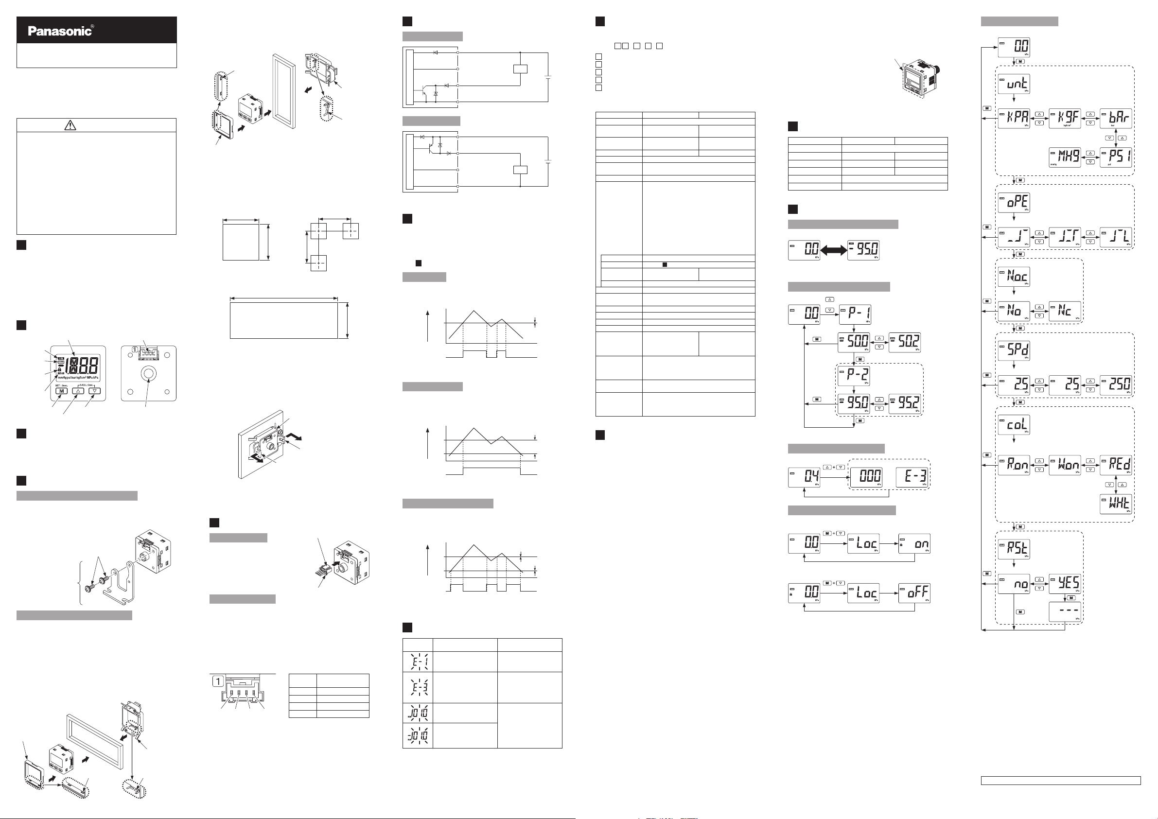
2 PART DESCRIPTION
Connecting connector
Pressure port
(M5 female thread)
ON mark
OFF mark
Key lock
mark
OVER mark
Mode selection key
Digital display unit
Setting value DOWN key
Setting value UP key
3 PIPING
● When using this product, connect a joint available
in the market to the pressure port. At the time, the
tightening torque should be 1.0 N·m or less.
4 MOUNTING
Sensor mounting bracket MS-DP1-1
● When mounting this product with sensor mount-
ing bracket, etc., the tightening torque should be
0.5 N·m or less.
M3 (length 6 mm) screws with
washer (Accessory with MS-DP1-1)
Sensor mounting bracket
MS-DP1-1
Panel mounting bracket MS-DP1-8
<How to mount>
1. Fit the panel mounting adapter on the front side
of the sensor. Mounting direction of the panel
mounting adapter differs depending on the
mounting direction of the panel mounting bracket.
● For horizontal adjacent mounting
• Mount the panel mounting adapter and the
panel mounting bracket so that the xing hooks
are vertical.
Panel mounting
adapter
Fixing hooks Fixing hooks
Panel mounting
bracket
-
● For vertical adjacent mounting
• Mount the panel mounting adapter and the
panel mounting bracket so that the xing hooks
are horizontal.
Fixing hooks
Panel mounting
bracket
Fixing hooks
Panel mounting adapter
2. Insert to the panel, in condition 1.
3. Insert the panel mounting bracket from the rear
side of the sensor till it touches the panel.
<Dimensions of panel cutout>
● For single mounting (Unit: mm)
0
31
-
0.4
0
(Panel thickness: 1 to 3)
0.4
-
31
55 or more
55 or more
● For adjacent mounting (Unit: mm)
X
0
0.4
-
31
When n pieces are mounted
X = 31 × n + 3.5 × (n - 1)
Note: In case of adjacent mounting, be sure to keep apart from each other
in 55mm or more as well as for single mounting.
<How to remove>
● Pull out the panel mounting bracket while pushing
the removing levers out.
Panel mounting bracket
Removing lever
Removing lever
Notes: 1) Take care that it the sensor is forcibly pulled, the sensor itself or
the panel mounting bracket may break.
2) Do not reuse the panel mounting adapter which has been used
once.
5 WIRING
How to connect
● Insert the cable with con-
nector CN-14A-C□ into this
product’s connection connector section as shown in
the right gure.
How to disconnect
● Pressing the release lever
of the cable with connector,
pull out the connector.
Note: Do not pull by holding the cable without pressing the release lever,
as this can cause cable break or connector break.
<Connector pin arrangement>
1 2 3 4
Release lever
Cable with connector
CN-14A-C□
<Recommended product>
Contact:
SPHD-001T-P0.5
Housing: PAP-04V-S
[Manufactured by JST Mfg. Co., Ltd.]
Connector
pin No.
Note: Open or, Connect to 0 V.
Terminal name
1 +V
2 Comparative output
3 No connection (Note)
4 0 V
6 I/O CIRCUIT DIAGRAMS
NPN output type
(Brown) +V
Main circuit
(White) No connection
(Note)
(Black) Comparative output
(Blue) 0 V
Load
+
−
12 V DC to 24 V DC±10 %
PNP output type
(Brown) +V
(Black) Comparative output
Main circuit
Note: Open or, Connect to 0 V.
7
OUTPUT MODE AND OUTPUT OPERATION
(White) No connection
(Note)
(Blue) 0 V
Load
+
−
12 V DC to 24 V DC±10 %
● The EASY mode, hysteresis mode or window
comparator mode can be selected as the output
mode.
For details, refer to <Detailed setting mode> in
12
Menu setting mode.”
“
EASY mode
● The comparative output ON / OFF state can be
controlled in this mode.
P-1
Pressure
0
Comparative
output
H: Hysteresis xed (4 digits)
(10 digits or more when the product is for overseas use and used in units of psi.)
OFF
ON
H (Hysteresis)
Hysteresis mode
● The comparative output ON / OFF state can be
controlled with randomly set hysteresis in this
mode.
P-2
Pressure
P-1
0
Comparative
output
H: 2 digits or more
(5 digits or more when the product is for overseas use and used in units of psi.)
OFF
ON
H (Hysteresis)
Window comparator mode
● In this mode, the ON or OFF state of the compar-
ative output is controlled with a pressure in the
set range.
P-2
Pressure
P-1
0
Comparative
output
H: Hysteresis xed (4 digits)
(10 digits or more when the product is for overseas use and used in units of psi.)
OFF
ON
H (Hysteresis)
H (Hysteresis)
8 ERROR INDICATION
Error
indication
When other error massage is displayed, contact us.
Description Remedy
The load is short-circuited
causing an overcurrent to
ow.
When the zero-adjustment
function is implemented,
pressure is applied.
The applied pressure exceeds the upper limit of the
displayed pressure range.
The applied pressure exceeds the lower limit (back
pressure) of the displayed
pressure range.
Turn OFF the power and
check the load.
Reset the voltage applied to
the pressure port to the
atmospheric pressure and
implement the zeroadjustment function again.
Applied pressure range
should be brought within
the rated pressure range.
9 SPECIFICATIONS
● Model No.
1 2-3-4-5
DP-00
1
: 1: Low pressure type, 2: High pressure type
2
:
None: For outside of Japan, Z: For inside of Japan
3
: None: NPN output type, P: PNP output type
4
:
None: With cable with a connector, J: Without attachment
5
: None: Without attachment
H1: With sensor mounting bracket
H2: With panel mounting bracket
Type Low pressure type High pressure type
Pressure type Gauge pressure
Rated pressure range
Displayable / settable
pressure range
Pressure resistance
Applicable uid Air, Non-corrosive gas
Supply voltage
Current consumption
Comparative
output
Output operation
Hysteresis
Repeatability
Response time
Protection IP40 (IEC)
Ambient temperature
Ambient humidity
Pollution degree 2
Overvoltage category
Usable altitude 2,000 m or less
Temperature
characteristics
(+20 °C standard)
Material
Weight
(Main body only)
Accessories
10
CAUTIONS
● This product has been developed / produced for
industrial use only.
● The product shall be used only within the rated
pressure range.
Do not apply pressure exceeding the pressure resis-
●
tance. Otherwise, destruction of diaphragm occurs,
preventing the product to perform normal operation.
● Make sure that the power supply is OFF while
performing the wiring operation.
● Verify that the supply voltage variation is within
the rating.
If power is supplied from a commercial switching reg-
●
ulator, ensure that the frame ground (F.G.) terminal of
the power supply is connected to an actual ground.
● In case noise generating equipment (switching
regulator, inverter motor, etc.) is used in the vicinity of this product, connect the frame ground (F.G.)
terminal of the equipment to an actual ground.
● Do not use during the initial transient time (0.5
sec.) after the power supply is switched ON.
When extending the cable, use a cable whose con-
●
ductor cross-sectional area is 0.3 mm2 or more. The
cable can be extended to up to 10 m in total length.
●
Do not run the wires together with high-voltage lines
or power lines or put them in the same raceway.
This can cause malfunction due to induction.
● The specication may not be satised in a strong
magnetic eld.
● This product is suitable for indoor use only.
● Take care that an excessive stress is not applied
to the unit. Otherwise, pressure values may vary.
Take care that strong impact such as fall is not giv-
●
en to this product. Otherwise, it may be destroyed.
● Avoid dust, dirt, and steam.
● When cleaning, wipe o with a soft cloth that does
not make dirt.
● Take care that the product does not come into
contact with organic solvents such as thinner.
● Take care that the product does not come into
contact with oil or grease.
● Take care that the product does not come into
contact with strong acid or alkaline.
● Do not insert wire into the pressure port. Other-
wise, destruction of diaphragm occurs, preventing
the product to perform normal operation.
-100.0 kPa to
+100.0 kPa
-101.0 kPa to
+101.0 kPa
500 kPa 1.5 MPa
12 V DC to 24 V DC ±10 % Ripple P-P 10 % or
<NPN output type>
NPN open-collector transistor
• Maximum sink current: 50 mA
• Applied voltage: 30 V DC or less
(between comparative output and 0 V)
Residual voltage: 2 V or less (at 50 mA sink current)
•
<PNP output type>
PNP open-collector transistor
• Maximum source current: 50 mA
• Applied voltage: 30 V DC or less
(between comparative output and + V)
•
Residual voltage: 2 V or less (at 50 mA source current)
Selectable either NO or NC, with key operation
7
OUTPUT MODE AND OUTPUT OPERATION”
Refer to “
±0.2 % F.S.
(within ±4 digits)
2.5 ms / 25 ms / 250 ms Selected by key operation
0 °C to +50 °C (No dew condensation)
Storage: -10 °C to +60 °C
35 % RH to 85 % RH, Storage: 35 % RH to 85 % RH
+10 °C to +40 °C:
Within ±1 % F.S.
0 °C to +50 °C:
Within ±2.5 % F.S.
Enclosure: PBT, LCD display: Acryl
Pressure port: Brass-nickel plating
Mounting screw section: Brass, O-ring: Nitrile rubber (NBR)
Key section: Polycarbonate
CN-14A-C2 (Cable with a connector, 2 m long)
(optional for J type): 1 pc.
MS-DP1-1 (Sensor mounting bracket) (only H1 type): 1 pc.
MS-DP1-8 (Panel mounting bracket) (only H2 type): 1 pc.
less
30 mA or less
I
+10 °C to +40 °C:
0 °C to +50 °C:
Approx. 25 g
0.000 MPa to
+1.000 MPa
-0.010 MPa to
+1.010 MPa
±0.4 % F.S.
(within ±4 digits)
Within ±2 % F.S.
Within ±5 % F.S.
● Make sure that stress by forcible bend or pulling
is not applied to the sensor cable joint.
● Never disassemble or modify the product.
● Do not drop the product or
otherwise subject to strong
shock. Otherwise, the
product may be damaged.
● Do not apply an excessive
Front surface of the
product
load to the front surface
or corners of the product.
Otherwise, the product
may be damaged.
11
FACTORY SETTINGS
Type Low pressure type High pressure type
Operation setting EASY mode
NO / NC setting NC NO
Threshold value -50.0 0.500
Pressure unit kPa MPa
Display color Red when ON, White when OFF
Response speed 2.5 ms
12
MENU SETTING MODE
Display during output operation
Output OFF Output ON
*: Settings of output operation and display colors can be changed in "Dis-
play color setting mode" of "Setting mode."
Threshold value setting mode
RUN mode
*:
Displayed only when hysteresis mode / window comparator mode is set.
or
1 sec.
2 sec.
After 10 sec.
1 sec.
2 sec.
After 10 sec.
Zero point adjustment mode
RUN mode
2 sec.
When adjustable
3 sec.
When unadjustable
Key lock setting / release mode
<Setting of key lock>
2 sec.
1 sec.
1 sec.
<Release of key lock>
2 sec.
*: The key lock mark appears for 1 sec. when key operation is performed
in RUN state with the key lock set (turns OFF in RUN state).
1 sec.
1 sec.
Detailed setting mode
RUN mode
2 sec.
Pressure unit setting mode (Note 1)
1 sec.
kPa (Note 2)
2 sec.
Operation setting mode
1 sec.
EASY mode
2 sec.
NO / NC setting mode
1 sec.
NO
2 sec.
Response speed setting mode
1 sec.
2.5 ms 25 ms 250 ms
2 sec.
Display color setting mode
1 sec.
Red when ON
White when OFF
2 sec.
Settings initializing mode
1 sec.
No Yes
2 sec.
Notes: 1) The pressure unit setting mode is not displayed in the product
intended for use in Japan.
2) “MPa” is used for high pressure type.
3) “mmHg” is used only for low pressure type.
4) When setting change has been made, do not turn OFF the power supply within 5 sec. after returning to RUN mode.
2
mmHg (Note 3)
Hysteresis
mode
NC
White when ON
Red when OFF
1 sec.
barkgf/cm
psi
Window comparator mode
Always red
Always white
Panasonic Industry Co., Ltd.
1006, Oaza Kadoma, Kadoma-shi, Osaka 571-8506, Japan
https://industry.panasonic.com/
Please visit our website for inquiries and about our sales network.
Panasonic Industry Co., Ltd. 2024
April, 2024 PRINTED IN JAPAN
 Loading...