

Panasonic CX-400 Instructions Manual
1
MEUEN-CX400 V2.2
Thank you for purchasing products from Panasonic. Please read this
Instruction Manual carefully and thoroughly for the correct and optimum use
of this product. Kindly keep this manual in a convenient place for quick
reference.
This product is designed for industrial use only.
Make sure to carry out wiring with the power OFF.
Do not use this product in an environment with inflammable or explosive
gas.
Incorrect wiring will damage the sensor.
Verify that the supply voltage including the ripple is within the rating.
If power is supplied from a commercial switching regulator, ensure that
the frame ground (F.G.) terminal of the power supply is connected to an
actual ground.
In case noise generating equipment (switching regulator, inverter motor,
etc.) is used in the vicinity of this product, connect the frame ground
(F.G.) terminal of the equipment to an actual ground.
Do not run the wires together with high-voltage lines or power lines or put
them in the same raceway. This can cause malfunction due to induction.
Do not use during the initial transient time (50ms) after the power supply
is switched on.
This sensor is suitable for indoor use only.
You can extend the cable up to 100m max. with 0.3mm
2
or more cable
(thru-beam type, both emitter and receiver). However, in order to reduce
noise, make the wiring as short as possible.
To comply with the requirements for the Korean S-Mark, the power
supply line must be 10m or less.
Do not apply stress directly to the sensor cable joint by forcibly bending
or pulling.
Do not use this sensor in places having excessive vapor, dust, etc., or
where it may come in direct contact with water or corrosive gas.
Take care that the sensor does not come in direct contact with water, oil,
grease, or organic solvents such as thinners, etc.
Never disassemble or modify the product.
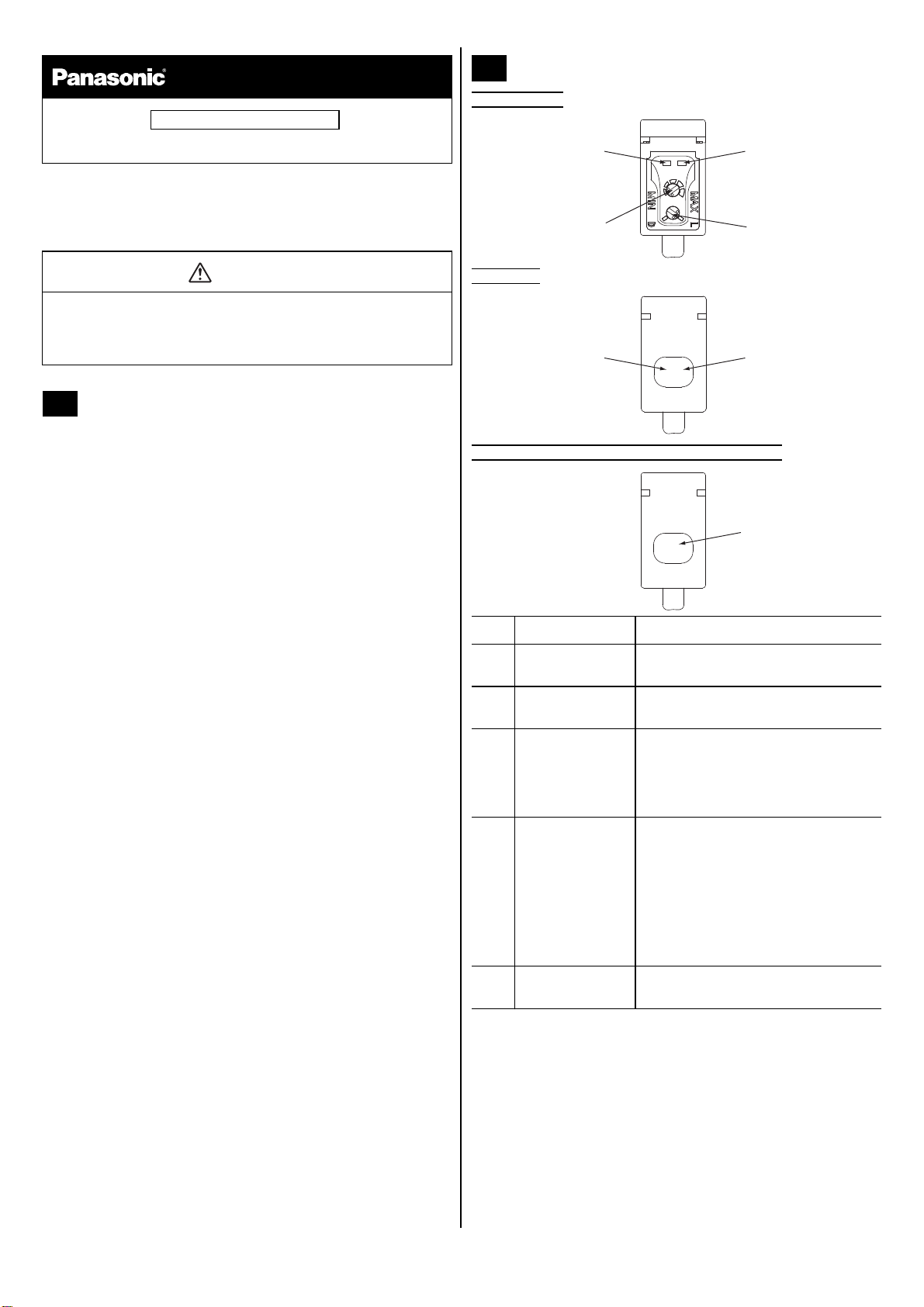
Standard type
Basic type
Thru-beam emitter for standard and basic types
INSTRUCTIONS
WARNING
• Never use this product as a sensing device for personnel protection.
• In case of using sensing devices for personnel protection, use
products which meet laws and standards, such as OSHA, ANSI or IEC
etc., for personnel protection applicable in each region or country.
1 CAUTIONS
2 PART NAMES
No. Part Description
1 Stability indicator
(green)
Lights up under the stable Light or stable
Dark condition.
2 Operation indicator
(orange)
Reflective type, thru-beam receiver:
lights up when the sensor output is ON.
3 Sensitivity adjuster Reflective type, thru-beam receiver:
sensing range increased when turned
clockwise.
See “SENSITIVITY ADJUSTMENT” on
page 4.
4 Operation mode
switch
Reflective type, thru-beam receiver:
• L: Light-ON
Light-ON mode is obtained when the
operation mode switch is turned fully
clockwise (L).
• D: Dark-ON
Dark-ON mode is obtained when the
operation mode switch is turned fully
counterclockwise (D).
5 Power indicator
(green)
Lights up when power in ON.
1
4
3
2
1
2
5
Compact Photoelectric Sensor
CX-400 Series
Ramco National
www.PanasonicSensors.com
1-800-280-6933
2
Connector cables for the M12 pigtailed type
Connector cables for the M8 connector type
Two sets of cables are required for the thru-beam type sensor.
The following symbols are used in this section.
Pin assignment
Only the thru-beam receiver incorporates the output.
NPN output type
Only the thru-beam receiver incorporates the output.
PNP output type
Only the thru-beam receiver incorporates the output.
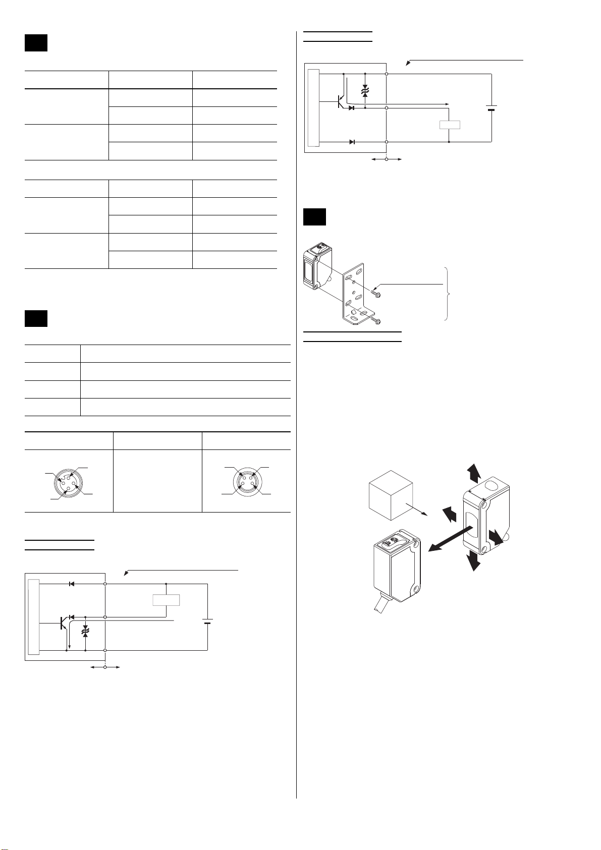
Mount the sensor with a tightening torque of 0.5N·m or less.
Thru-beam type sensor
1. Set the operation mode switch to the Light-ON mode position (L side).
2. Placing the emitter and the receiver face to face along a straight line.
Move the emitter up, down, left and right to determine where light is
received with the help of the receiver’s operation indicator (orange). Set
the emitter in the middle of this area.
3. Adjust the angle of the emitter by twisting it up, down, left and right.
4. In a similar manner, adjust the angle of the receiver.
5. Check that the stability indicator (green) lights up.
6. Choose the desired operation mode, Light-ON or Dark-ON, with the
operation mode switch.
3 CONNECTOR CABLES
Type Model no. Cable length
2-core type
CN-22-C2 2m
CN-22-C5 5m
4-core type
CN-24-C2 2m
CN-24-C5 5m
Type Model no. Cable length
Straight type
CN-24A-C2 2m
CN-24A-C5 5m
Elbow type
CN-24AL-C2 2m
CN-24AL-C5 5m
4 I/O CIRCUIT DIAGRAMS
Symbol Meaning
D Reverse supply polarity protection diode
Z
D Surge absorption zener diode
Tr NPN / PNP output transistor
M12 pigtailed type Terminal name M8 connector type
1) +V
2) Not connected
3) 0V
4) Output (see note)
1
2
3
4
1
2
3
4
D
T
r
ZD
ZD
+
-
±10%
100mA max.
Color code of cable with connector
(Brown / 1) +V
(Blue / 3) 0V
(Black / 4)
Output (note)
Load
Internal circuit Users' circuit
12 to 24V DC
Sensor circuit
5 MOUNTING AND ADJUSTING
D
T
r
ZD
+
-
±10%
ZD
100mA max.
(Brown / 1) +V
(Blue / 3) 0V
(Black / 4)
Output (note)
Load
12 to 24V DC
Internal circuit
Users' circuit
Color code of cable with connector
Sensor circuit
Sensor mounting
bracket (optional)
12mm M3 screws
with washers
Emitter
Receiver
Object to be sensed
Ramco National
www.PanasonicSensors.com
1-800-280-6933
3
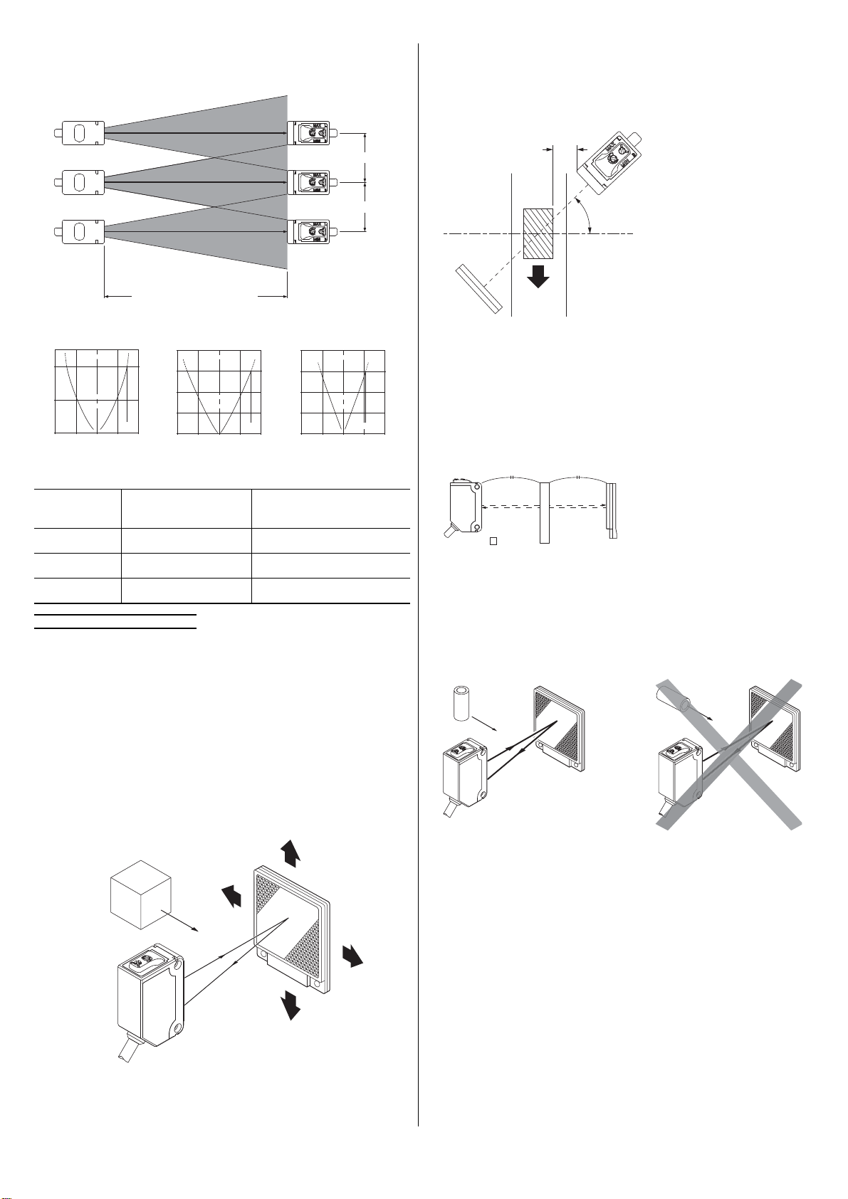
Installation interval
When mounting 2 or more sets of thru-beam type sensors side by side, they
must be separated by a certain interval to prevent interference.
Diagrams for establishing the operating point (ℓ), typical:
For example:
Retroreflective type sensor
Make sure to mount the sensor and the reflector at least 0.1mm
apart.
1. Set the operation mode switch to the Light-ON mode position (L side).
2. Placing the sensor and the reflector face to face along a straight line.
Move the reflector up, down, left and right to determine where light is
received the help of the operation indicator (orange). Set the reflector in
the middle of this area.
3. Adjust the angle of the reflector by twisting it up, down, left and right.
4. In a similar manner, adjust the angle of the sensor.
5. Check that the stability indicator (green) lights up.
6. Choose the deisred operation mode, Light-ON or Dark-ON, with the
operation mode switch.
When sensing glossy objects with CX-493 or transparent objects
with CX-48
These measures are not necessary for the retroreflective type with
polarizing filters CX-491.
1. Make sure the parallel distance (L) between the sensor and the object
being sensed is great enough. Otherwise light might be reflected and
erroneously detected by the sensor.
2. Install the sensor at an angle of 10 to 30° to the object being sensed.
When sensing transparent objects with CX-48
For optimum sensing, the distance should be the same between the
transparent object being sensed and the sensor and the transparent
object and the reflector. Otherwise, sensing may be unstable.
When the sensor detects an irregular plastic receptacle or glass bottle,
the received light intensity may differ with the sensing position or
direction. Adjust the sensitivity after confirming the stable sensing
condition by turning the sensing object, etc.
If the object is a transparent cylinder, feed it in a standing, not a lying,
position.
Model no. Sensing distance (L)
Installation interval
2 x ℓ
CX-411 10m Approx. 590mm or more
CX-412 15m Approx. 1,580mm or more
CX-413 30m Approx. 4.35m or more
*
Sensing distance (L)
Interval*
Interval*
Interval = 2 x
operating point (ℓ)
400
(ℓ)
200 0 200 400
5
10
(L)
0
1000
(ℓ)
500 0 500
1000
5
15
(L)
20
10
0
4
(ℓ)
2 0 2 4
10
30
(L)
40
20
0
CX-411 CX-412 CX-413
ℓ (mm) ℓ (mm) ℓ (m)
L (m)
L (m)
L (m)
Reflector
Sensor
Object to be sensed
10 - 30°
L
CX-48
L = L
CX-48□
CX-48□
OK
Ramco National
www.PanasonicSensors.com
1-800-280-6933
 Loading...