

Page 1
INSTALLATION AND OPERATING INSTRUCTIONS
MANUEL D'INSTALLATION ET D'UTILISATION
Room Air Conditioner
Climatiseur de fenêtre
Models, Modèles: CW-XC54HU
CW-XC54HK
Please read these operating instructions thoroughly
before using your air conditioner and keep for future
reference.
Il est recommandé de lire attentivement ce manuel avant
d'utiliser l'appareil. Conservez ce manuel.
For U.S. customers:
For assistance, please call: 1-800-211-PANA(7262) or
Register your product at : http://www.panasonic.com/register
For customers in Canada :
For assistance, please call : 905-624-5505
Au Canada : Pour de l'aide, composez le 905-624-5505.
CW382820391A
R
TEMPTEM
P
F
DRY
ECONOMY
FAN
COOL
O
P
E
R
A
T
I
O
N
O
P
E
R
A
T
I
O
N
OFF/ON
F
A
N
S
P
E
E
D
T
IM
E
R
M
O
D
E
Page 2

About the Controls on the Air Conditioner
Features and Installation
Before you call for service...
2
Safety Precautions
FOR YOUR RECORDS
Write the model and serial numbers here:
Model #
Serial #
You can find them on a label on the side of the unit.
Dealer's Name
Date Purchased
Staple your receipt here for proof of purchase.
Inside you will find many helpful hints on how to use and
maintain your air conditioner properly. Just a little preventive
care on your part can save you a great deal of time and
money over the life of your air conditioner.
You'll find many answers to common problems in the chart
of troubleshooting tips. If you review our chart of
Troubleshooting Tips first, you may not need to call for
service at all.
READ THIS MANUAL
CAUTION
• Contact an Authorized Service Center for repair or
maintenance of this unit.
• The air conditioner is not intended for use by young
children or invalids without supervision.
• Young children should be supervised to ensure that
they do not play with the air conditioner.
Safety Precautions
Safety Precautions .............3
About the Controls
on the Air Conditioner
Controls..............................5
Air direction ........................8
Care and Maintenance ......8
Features
and Installation
Features .............................9
Window Requirements .....10
Electrical Data ..................12
Before You Call
For Service...
Normal Operation.............13
Abnormal Operation .........13
Page 3
WARNING
3
Safety Precautions
Safety Precautions
To prevent injury to the user or other people and property damage, the following instructions must be followed:
■ Incorrect operation will cause harm or damage. The seriousness is classified by the following indications.
■ Because of the weight of the product, it is recommended that you have a helper to assist in the installation.
■ Use Caution! Sharp Edges! See Warning, page 4.
WARNING : This symbol indicates the possibility of death or serious injury.
CAUTION
:
This symbol indicates the possibility of injury or damage to
property only.
■ Meanings of symbols used in this manual are as shown below.
Be sure not do this.
Be sure to follow the instructions.
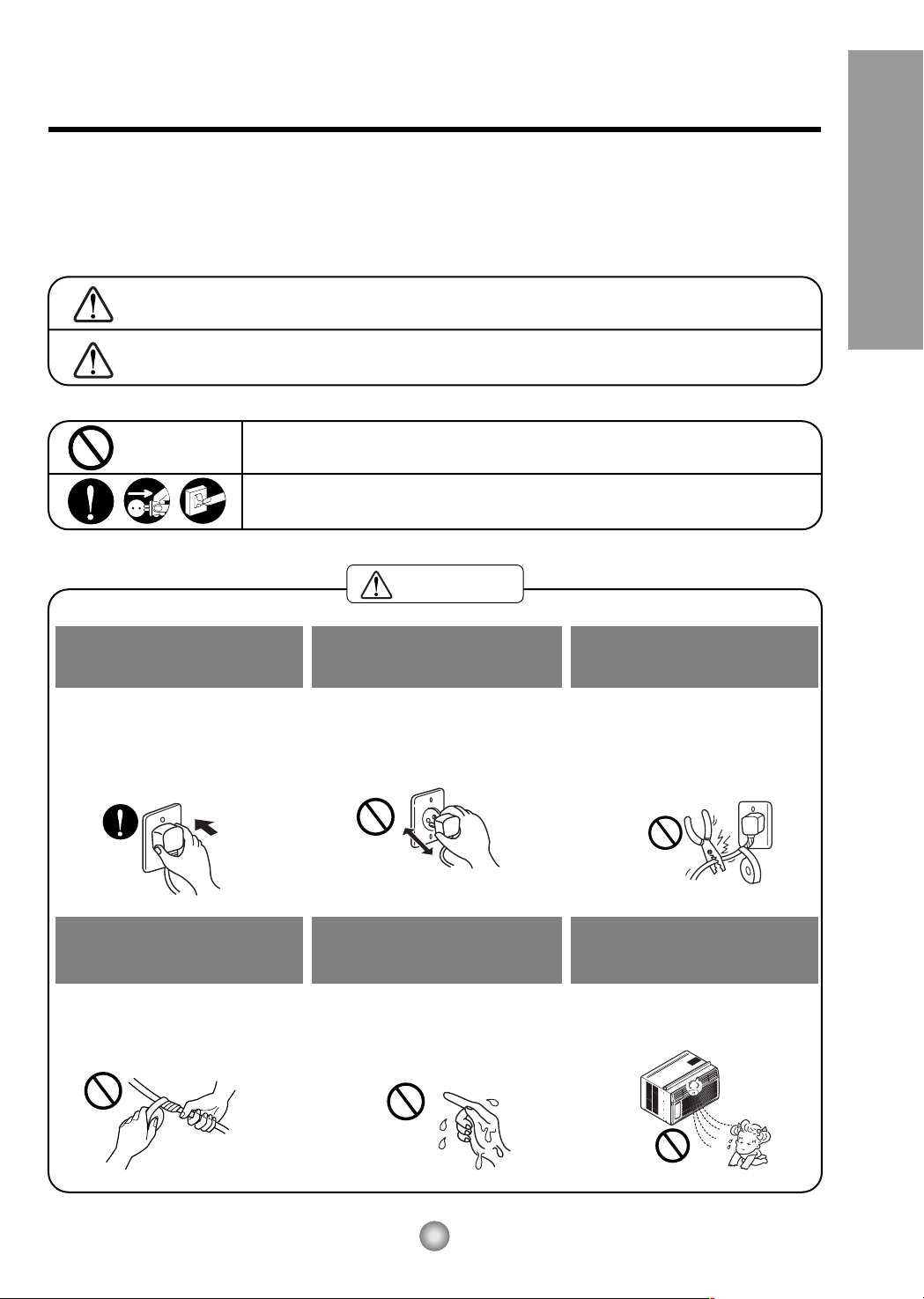
Plug in the power plug
properly.
• Otherwise, it will cause electric
shock or fire due to heat
generation.
Do not operate or stop the
unit by inserting or pulling
out the power plug.
• It will cause electric shock or fire
due to heat generation.
Do not damage or use an
unspecified power cord.
• It will cause electric shock or fire.
•
If the power cord is damaged, it must
be replaced by the manufacturer or
its service agent or a similarly
qualified person in order to avoid a
hazard.
Do not modify the length of
the power cord or use an
extension cord.
• It will cause electric shock or fire
due to heat generation.
Do not operate with wet
hands or in a damp
environment.
• It will cause electric shock.
Do not direct air flow at room
occupants.
• This could lead to health
problems.
Page 4
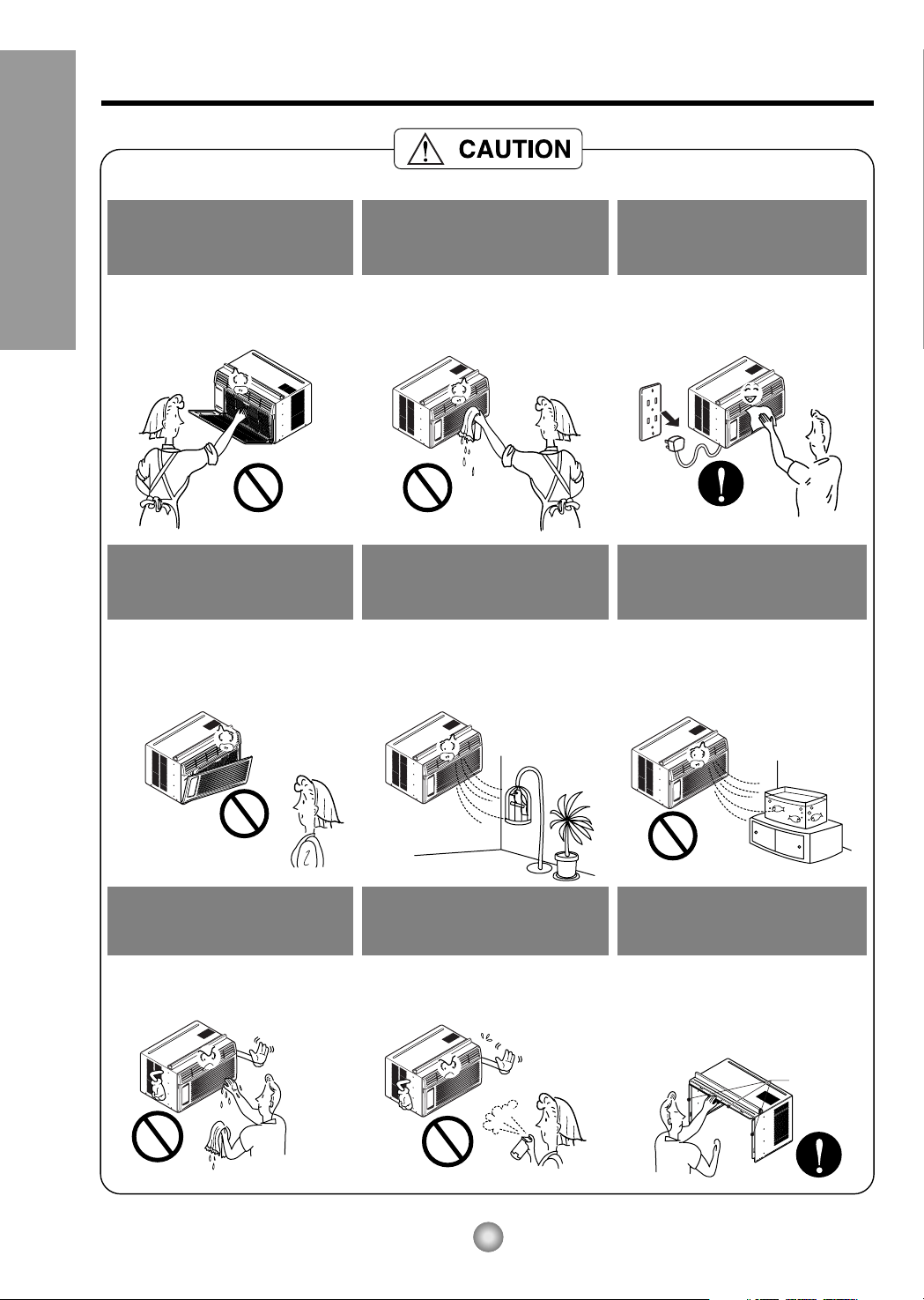
Sharp edges
When the air filter is to be
removed, do not touch the
metal parts of the unit.
• They are sharp and may cause
an injury.
Do not clean the air
conditioner with water.
• Water may enter the unit and
degrade the insulation. It may
cause an electric shock.
When the unit is to be
cleaned, switch the unit off,
and unplug it.
• Since the fan rotates at high
speed during operation, it may
cause an injury.
Do not operate the unit
without the air filter or when
the front intake grille has
been removed.
• It could cause dust to
accumulate on the heat
exchanger.
Do not put a pet or house
plant where it will be
exposed to direct air flow.
• This could injure the pets
or plants.
Do not use the unit for any
other purpose than its
intended use.
• Do not use this air conditioner to
preserve precision devices, food,
pets, plants, or art objects.
It may cause deterioration of
quality, etc.
Do not operate switches
with wet hands
.
• It may cause an electric shock.
Do not apply an insecticide
or flammable spray.
• It may cause a fire or damage of
the cabinet.
SHARP EDGES!
• Use caution when handling the
case. Grip it firmly and do not allow
it to slip while holding it.
• Use heavy gloves to handle the
case if necessary.
4
Safety Precautions
Page 5
About the Controls on the Air Conditioner
5
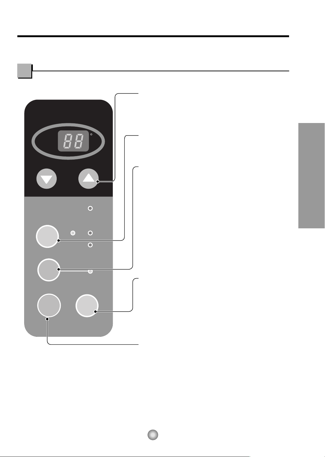
About the Controls on the air conditioner
The controls will look like the following.
Controls
hr
F
FAN
COOL
DRY
ECONOMY
FAN
SPEED
MODE
TEMP
OPERATION
OFF/ON
TIMER
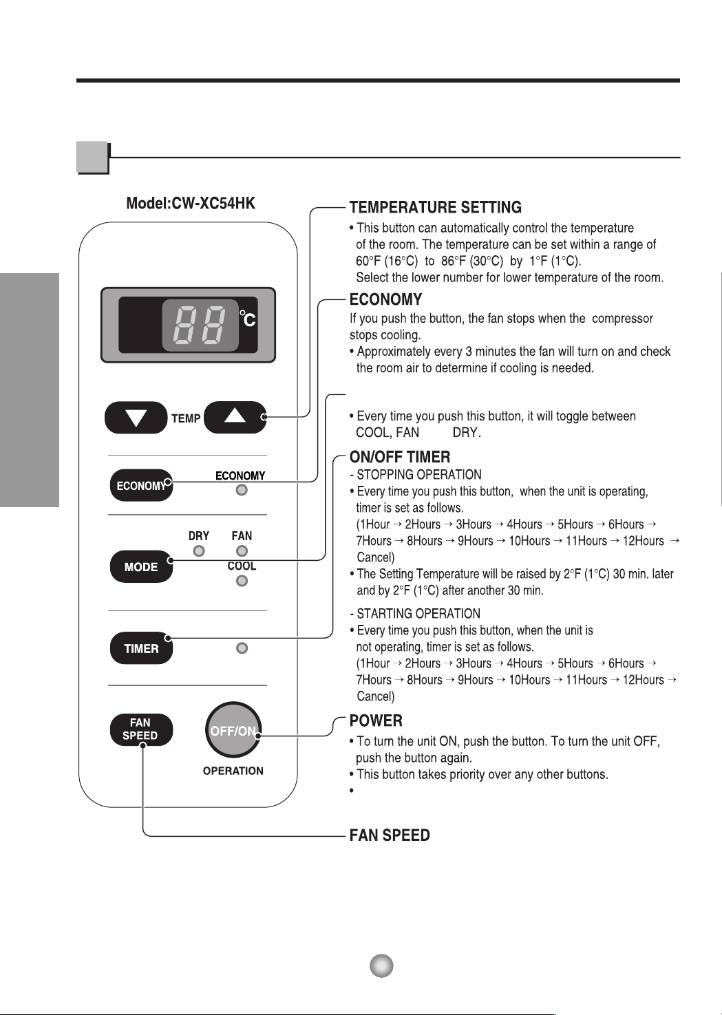
ON/OFF TIMER
- STOPPING OPERATION
• Every time you push this button, when the unit is operating,
timer is set as follows.
(1Hour → 2Hours → 3Hours → 4Hours → 5Hours → 6Hours →
7Hours → 8Hours → 9Hours → 10Hours → 11Hours → 12Hours → Cancel)
• The Setting Temperature will be raised by 2°F (1°C) 30 min. later
and by 2°F (1°C) after another 30 min.
- STARTING OPERATION
• Every time you push this button, when the unit is
not operating, timer is set as follows.
(1Hour → 2Hours → 3Hours → 4Hours → 5Hours → 6Hours →
7Hours → 8Hours → 9Hours → 10Hours → 11Hours → 12Hours → Cancel)
MODE
• Every time you push this button, it will toggle between
COOL, ECONOMY, FAN and DRY.
POWER
• To turn the unit ON, push the button. To turn the unit OFF,
push the button again.
• This button takes priority over any other buttons.
• When you first turn it on, the unit is on the High cool mode
and the temp. at 72°F (22°C).
TEMPERATURE SETTING
Model: CW-XC54HU
• This button can automatically control the temperature
of the room. The temperature can be set within a range of
60°F (16°C) to 86°F (30°C) by 1°F (1°C).
Select the lower number for lower temperature of the room.
FAN SPEED
• Every time you push this button it is set as follows.
{High(F2)
→
Low(F1)
→
High(F2)...}.
DRY
• When this unit is in dry mode, the fan rotates at low speed.
The fan stops when the compressor stops cooling.
Approximately every 3 minutes the fan will turn on and the unit
checks the room air temperature to set itself.
Page 6
6
About the Controls on the Air Conditioner
MODE
and
• Every time you push this button it is set as follows.
{High(F2) → Low(F1) → High(F2)...}.
DRY
• When this unit is in dry mode, the fan rotates
at low speed. The fan stops when the
compressor stops cooling.
Approximately every 3 minutes the fan will turn
on and the unit checks the room air
temperature to set itself.
hr
When you first turn it on, the unit is on the High cool mode
and the temp. at 72°F(22°C)
Controls
Page 7
7
About the Controls on the Air Conditioner
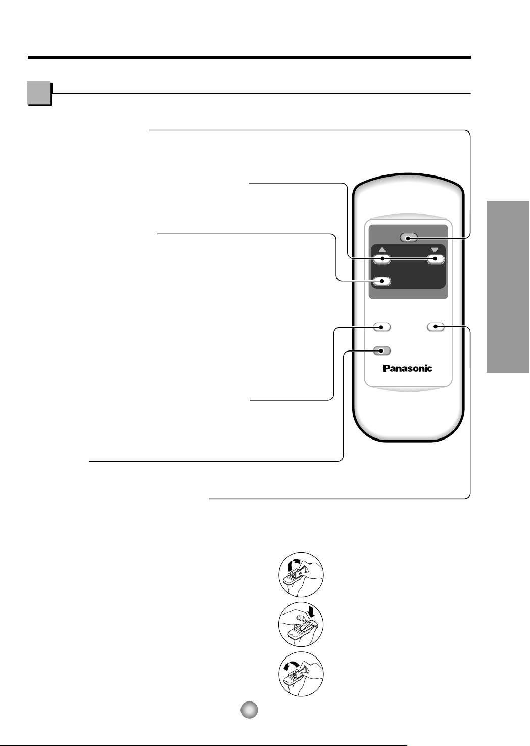
Remote controller
Precaution:
The Remote Controller will not function properly if strong light strikes the sensor window of the air
conditioner or if there are obstacles between the Remote Controller and the air conditioner.
1. Remove the cover from the back of the remote
controller
2. Insert two batteries.
• Be sure that the (+) and (-) directions are correct.
• Be sure that both batteries are new.
3. Re-attach the cover.
• Do not use rechargeable
batteries. Such batteries
differ from standard dry
cells in shape, dimensions,
and performance.
• Remove the batteries from
the remote controller if the
air conditioner is not going
to be used for an extended
length of time.
How to Insert Batteries
OPERATION
TEMP
TIMER
MODE
ECONOMY
FAN SPEED
ROOM TEMPERATURE SETTING BUTTON
ECONOMY
ON/OFF TIMER BUTTON
OPERATION BUTTON
FAN SPEED SELECTION BUTTON
OPERATION MODE SELECTION BUTTON
• To turn the air conditioner ON, push the button. To turn the air conditioner OFF, push the button again.
• This button takes priority over any other buttons.
• When you first turn it on, the air conditioner is on the High cool mode and the temp. at 72°F (22°C).
•
Every time you push this button, it will toggle between COOL, FAN and DRY.
(Model:CW-XC54HK)
•
Every time you push this button,it will toggle between COOL, ECONOMY, FAN
and DRY. (Model:CW-XC54HU)
• If you push this button, the fan stops when the compressor stops cooling. Approximately every
3 minutes the fan will turn on and check the room air to determine if cooling is needed.
• You can set the time when the unit will turn on or turn off automatically by pressing the timer
button. If the unit is in operation, this button controls the time it will be turned off. If the unit is
in off state, this button controls the time it will start. Every time you push this button, the
remaining time will be set as follows:
- STOPPING OPERATION
• Every time you push this button, when the air conditioner is operating, timer is set as
follows : (1Hour
→
2Hours → 3Hours → 4Hours → 5Hours → 6Hours → 7Hours →
8Hours
→
9Hours → 10Hours → 11Hours → 12Hours → 0Hour → 1Hour → 2Hours → ...)
• The Setting Temperature will be raised by 2°F (1°C) 30 min. later and by 2°F (1°C) after
another 30 min.
- STARTING OPERATION
• Every time you push this button, when the air conditioner is not operating, timer is set as
follows : (1Hour
→
2Hours → 3Hours → 4Hours → 5Hours → 6Hours → 7Hours →
8Hours → 9Hours →10Hours → 11Hours → 12Hours → 0Hour → 1Hour → 2Hours → ...)
Every time you push this button, it is set as follows.
{High(F2)
→
Low(F1) → High(F2)...}.
This button can automatically control the temperature of the room. The temperature
can be set within a range of 60°F to 86°F by 1°F. (16°C to 30°C by 1°C)
Select the lower number for lower temperature of the room.
Page 8
8
Features and Installation
Do not force open
or open too
far (about 56°)
Fig. 1
Fig. 2
Fig. 3
Fig. 4
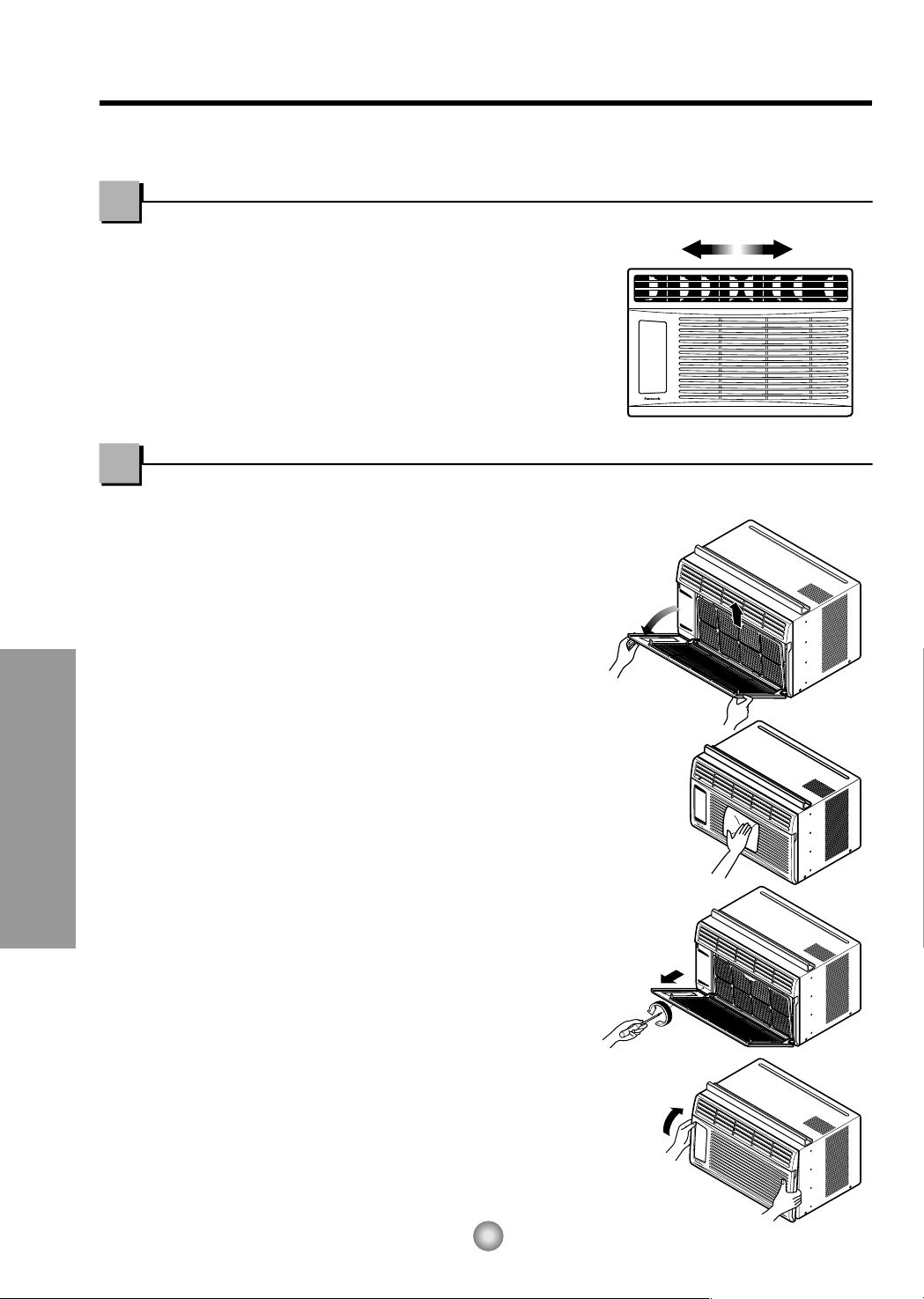
TURN THE AIR CONDITIONER OFF AND REMOVE THE PLUG FROM THE POWER OUTLET.
• TO CLEAN FILTER
The air filter will become dirty as it removes
dust from the inside air.
It should be washed at least every 2 weeks.
If the air filter remains full of dust, the air
flow will decrease and the cooling capacity
will be reduced, possibly damaging the unit.
1. Pull the inlet grille forward and pull out the
air filter. (Fig. 1)
2. Wash the air filter in warm 104°F (40°C) water.
Be sure to shake off all the water before
replacing the filter.
• CLEANING THE AIR CONDITIONER
The front grille and inlet grille may be wiped with a
cloth dampened in a mild detergent solution. (Fig. 2)
The cabinet may be washed with mild soap or
detergent and lukewarm water, then polished with
a liquid wax used for appliances.
To ensure continued peak efficiency, the condenser
coils (outside of unit) should be checked
periodically and cleaned if clogged with soot or
dirt from the atmosphere.
• HOW TO REMOVE THE FRONT GRILLE
1. Pull the inlet grille forward.
2. Remove the screw securing the front grille. (Fig. 3)
3. Push the grille up from the bottom and pull
the top of the grille away from the case as
the top tabs lift out of their slots. (Fig. 4)
Additional controls and important information.
Care and Maintenance
Air Direction
• ADJUSTING THE AIR DIRECTION USING THE HORIZONTAL AIR-DEFLECTOR CONTROL
Using the control tabs, the air flow can be directed
to the left, right, straight ahead, or any combination
of these directions.
Page 9
1
8
5
3
2
6
T
E
M
P
T
E
M
P
F
DRY
ECO
NOMY
FAN
COOL
O
P
E
R
A
T
I
O
N
O
P
E
R
A
T
I
O
N
O
FF
/ON
F
A
N
S
P
E
E
D
T
IM
E
R
M
O
D
E
T
E
M
P
T
E
M
P
F
DR
Y
EC
ON
OM
Y
F
AN
C
OO
L
O
P
E
R
A
T
IO
N
O
P
E
R
A
T
IO
N
O
F
F/
ON
F
A
N
S
P
E
E
D
T
IM
E
R
M
O
D
E
7
9
4
10
Wire net
Groove
Features and Installation
9
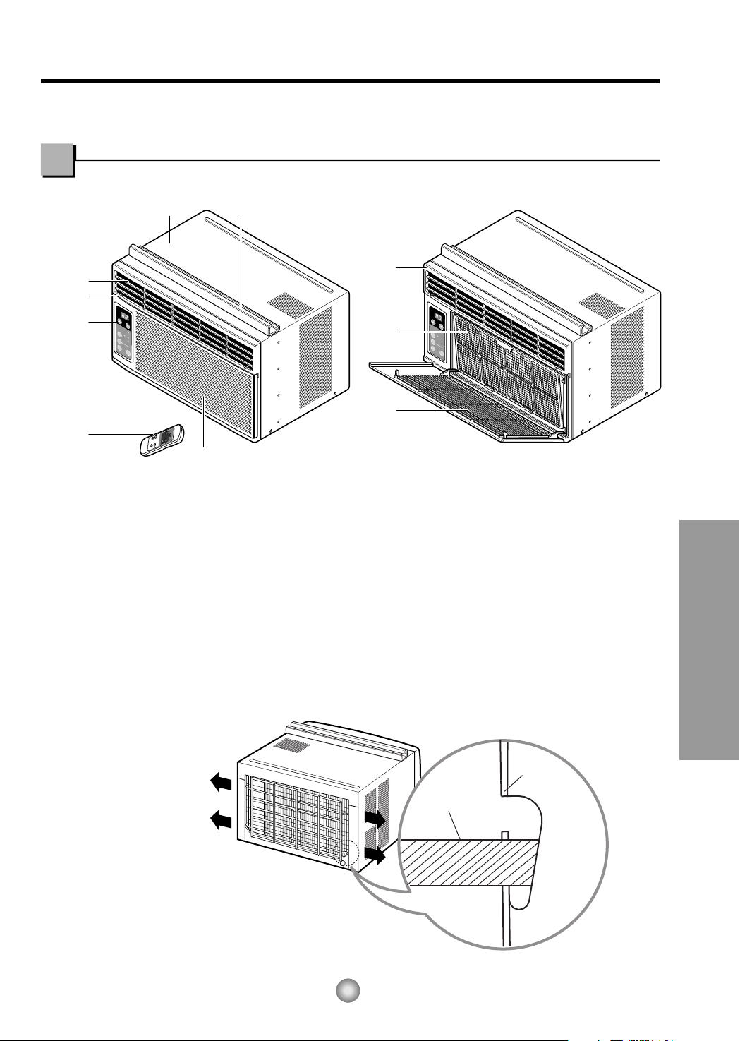
Learning parts name prior to installation will help you understand the installation procedure.
Features
■ How to install wire net on the back side of the cabinet
(Optional : CW353020031B)
Insert the rear grill wire ends into the 4 respective slots provided along the groove at the back of unit.
1. CABINET
2. HORIZONTAL AIR DEFLECTOR
3. COOL AIR DISCHARGE
4. FRONT GRILLE
5. INLET GRILLE
6. AIR FILTER
7. CONTROL BOARD
8. AIR INTAKE
9. UPPER GUIDE
10. REMOTE CONTROLLER
Features and Installation
Page 10
10
Features and Installation
OUTDOORSINDOORS
INNER
SILL
OUTER
SILL
INNER
SILL
WOOD STRIP MOUNTED
ON TOP OF INNER SILL
1"
WOOD STRIP
FOR
L
BRACKET
3
/4"
CLEARANCE
STORM
WINDOW
FRAME
OUTDOORSINDOORS
OUTER
SILL
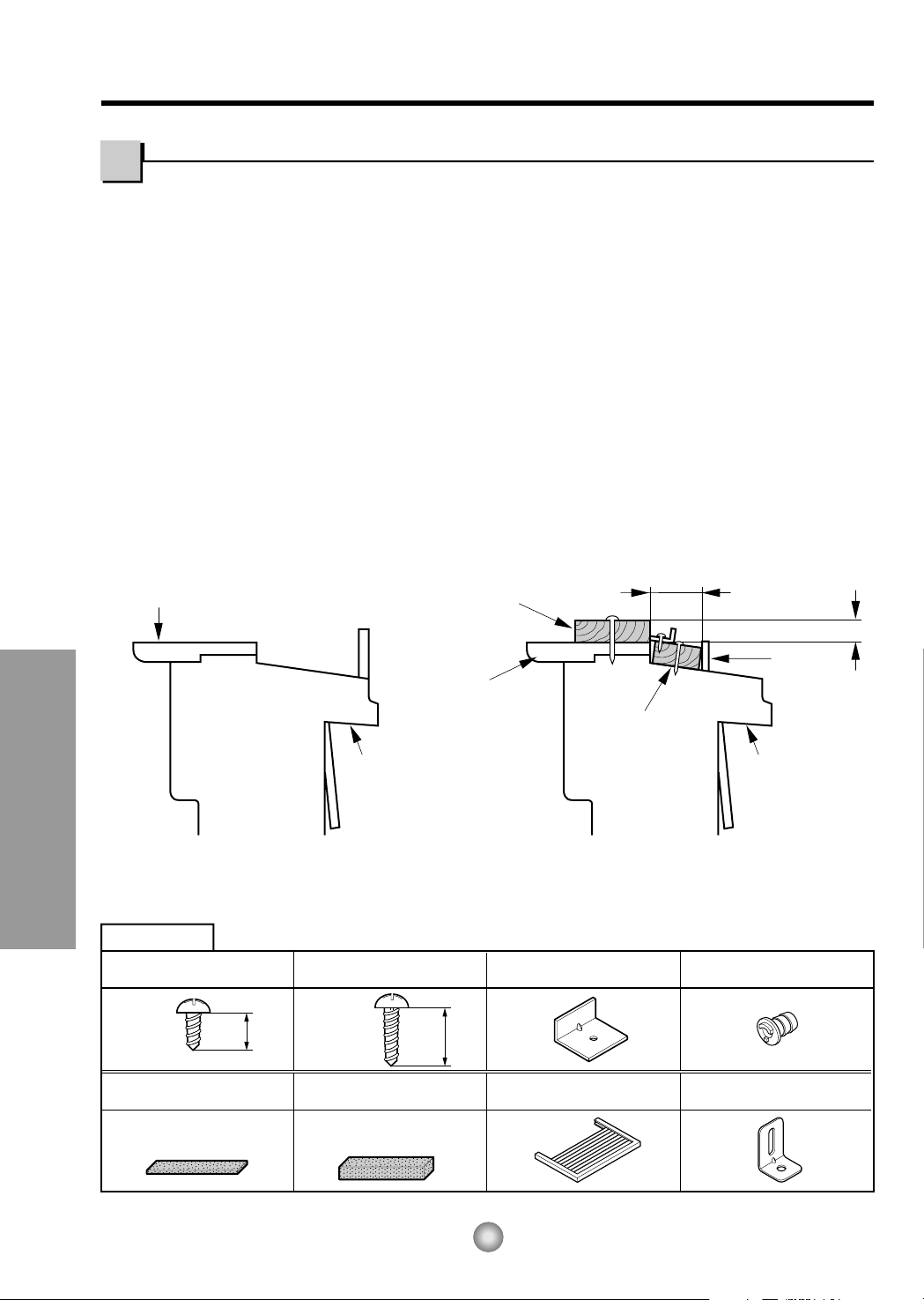
TYPE B: Qty:5
(WOOD SCREW)
HARDWARE
TYPE A: Qty:11
(SHORT SCREW)
TYPE C: Qty:3
(L BRACKET)
TYPE E: Qty:1
(SASH SEAL)
(Not adhesive backed)
TYPE D: Qty:1
(SEAL STRIP)
(Adhesive backed)
TYPE F: Qty:2
(GUIDE PANEL)
TYPE G: Qty:1
(SUPPORT BRACKET)
25/64"
(10mm)
5/8"
(16mm)
DRAIN PIPE
Qty:1
NOTE: All supporting parts should be secured to firm wood, masonry, or metal.
1. This unit is designed for installation in standard double hung windows with actual opening widths of
22" to 36". The upper and lower sash must open sufficiently to allow a clear vertical opening of 13"
from the bottom of the sash to the window stool.
2.If a storm window presents interference, fasten a 2" wide wood strip to the inner window sill across
the full width of the sill. The wood strip should be thick enough to raise the height of the window sill
so that the unit can be installed without interference by the storm window frame.
See Fig. 5-2. The top of the wood strip should be approximately
3
/4" higher than the storm window
frame (STORM WINDOW FRAME) or wood strip (OUTDOORS) to help condensation to drain
properly to the outside.
3. Install a second wood strip (approximately 18" long by 1
1
/2" wide and same thickness as first strip)
in the center of the outer sill flush against the back off the inner sill. This will raise the L bracket as
shown in Fig. 5-2.
4. The thickness of the second wood strip may not be the same as the first wood strip.
The thickness of the second wood strip must be defined to keep the
3
/4 inch distance between the
inner sill or the top of the first wood strip and the outer sill.
Window Requirements
Installation
Fig. 5-1
Fig. 5-2
Page 11
ROOM SIDE
CENTER LINE
INNER SILL
SEAL STRIP
(TYPE D)
CENTER LINE
OUTSIDE
INSIDE
L
BRACKET
OUTER SILL
INNER SILL
TYPE A
8"
8"
CENTER LINE
SEAL
WINDOW FRAME
BOTTOM
GUIDE
ABOUT
1/4"
L
BRACKET
UPPER GUIDE
TYPE A
TYPE A
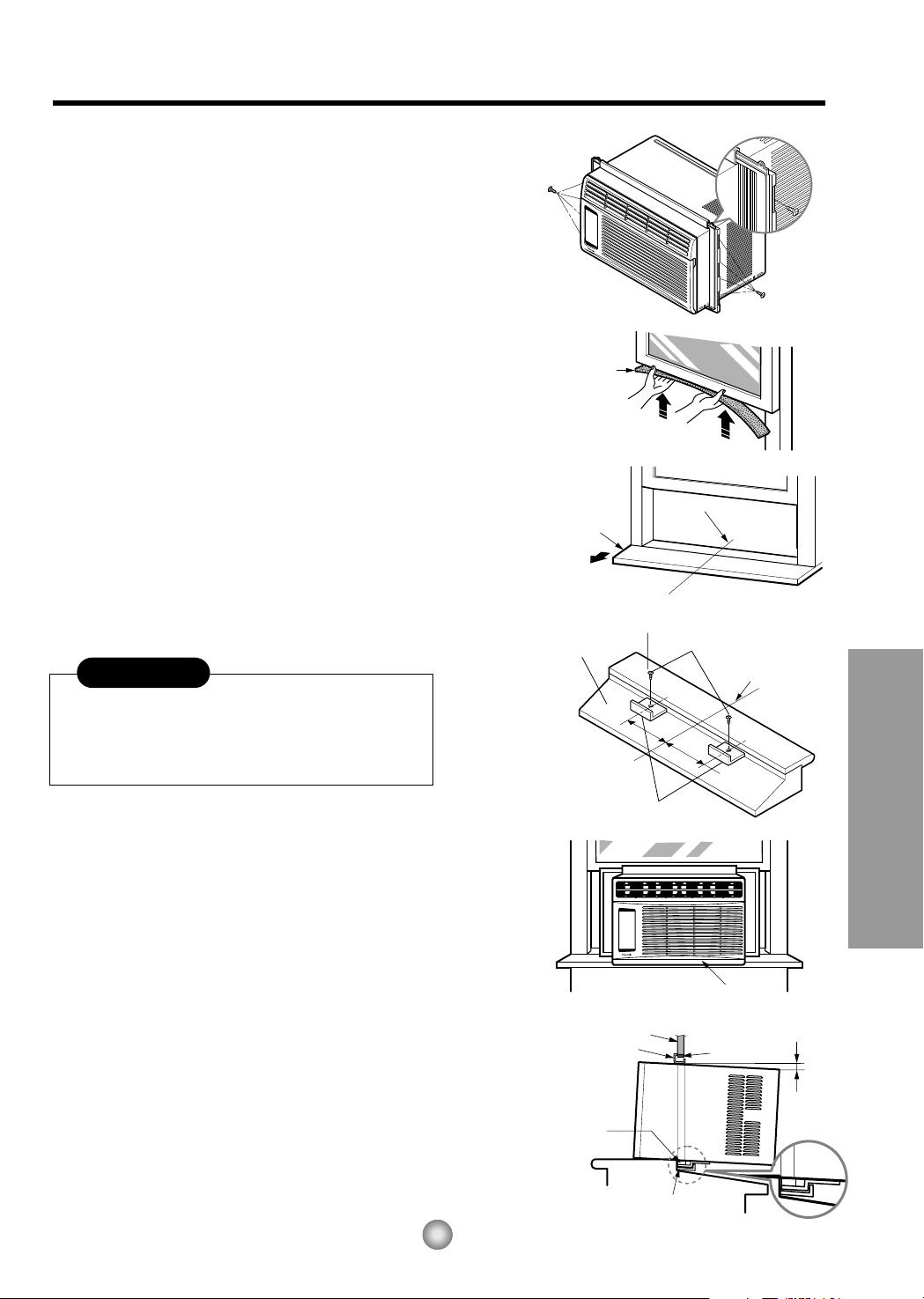
A. BEFORE INSTALLATION
1. Insert the guide panels into the guides of the air
conditioner. Fasten the curtains to the unit with
screws (TYPE A), as shown Fig. 6.
2. Cut the adhesive-backed seal strip (TYPE D) to the
window width.
Remove the backing from the seal strip and attach
the seal strip to the underside of the bottom
window. (Fig. 7)
B. NOW START INSTALLATION
1. LOCATING UNIT IN A WINDOW
Open the window and mark center line on the
center of the inner sill, as shown in Fig. 8.
2. ATTACH L BRACKET
a. Install the L brackets behind the inner window
sill, with short side of bracket as shown. Use the
2 screws (TYPE A) provided.
b. The bracket helps to hold the unit securely in
place. Be sure to place bracket edge flush
against back of inner sill. See Fig. 9.
3. INSTALL THE AIR CONDITIONER IN THE
WINDOW
a. Carefully lift the air conditioner and slide it into
the open window. Make sure the bottom guide of
the air conditioner drops into the notches of the
L bracket. See Fig. 9.
IMPORTANT :
When the air conditioner drops into the L bracket, the
air conditioner will be centered in window opening as
shown in Fig. 10.
b. While steadying the air conditioner, carefully
bring the window sash down behind the upper
guide of the air conditioner, as shown in Fig. 11.
Fig. 6
Fig. 7
Fig. 8
Fig. 9
Fig. 10
Fig. 11
During the following step, hold unit firmly until
window sash is lowered to top channel behind
side panel frames. Personal injury or property
damage may result if unit falls from window.
CAUTION
11
Features and Installation
Page 12
12
Features and Installation
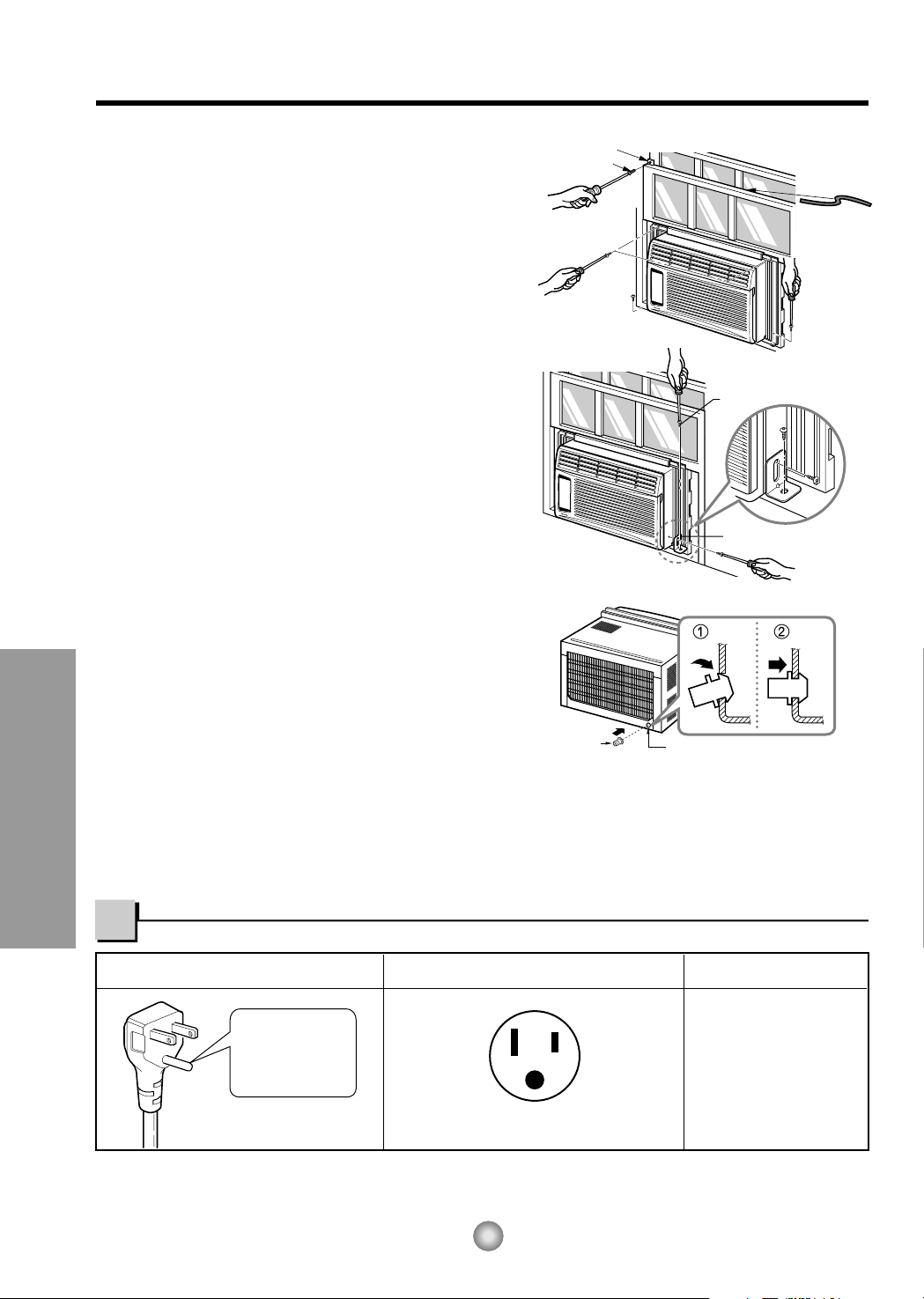
Do not under any
circumstances cut
or remove the
grounding prong
from the plug.
Line Cord Plug Use Wall Receptacle Power Supply
Power supply cord with
3-prong grounding plug
Standard 125V, 3-wire grounding
receptacle rated 15A, 125V AC
Use 15 AMP, time
delay fuse or circuit
breaker.
SASH SEAL
(TYPE E)
L BRACKET
TYPE A
DRAIN PIPE
DRAIN CAP
TYPE B
Support Bracket (TYPE G)
Fig. 12
Fig. 13
Fig. 14
4. SECURE THE GUIDE PANELS
Extend the guide panels (TYPE F) to fill the window
opening using 4 screws (TYPE B) to secure them, as
shown in Fig. 12.
5. INSTALL THE SASH SEAL AND SASH LOCK
a. Cut the sash seal (TYPE E) to the window width.
Stuff the sash seal between the glass and the
window to prevent air and insects from getting into
the room, as shown in Fig. 12.
b. Fasten the L bracket using a screw (TYPE A), as
shown in Fig. 12.
6. a. Remove the screws that secure the cabinet and
base pan in the right side.
b.
Fasten the support bracket (TYPE G) using a
removed screw. Attach the support bracket (TYPE G)
in the inner window sill with a screw (TYPE B), as
shown Fig. 13.
7. Window installation of room air conditioner is now
completed. See ELECTRICAL DATA for attaching
power cord to electrical outlet.
C. HOW TO SECURE THE DRAIN PIPE
In humid weather, excess water may cause the BASE
PAN to overflow. To drain the water, remove the
DRAIN CAP and secure the DRAIN PIPE to the rear
hole of the BASE PAN. (Fig. 14) Press the drain pipe
into the hole by pushing down and away from the fins
to avoid injury.
REMOVAL FROM WINDOW
Turn the air conditioner off, disconnect the power cord, remove the Support Bracket, L bracket and the screws
installed through the top and bottom of the guide panels, and save for reinstallation later. Close the guide panels.
Keeping a firm grip on the air conditioner, raise the sash, and carefully tilt the air conditioner backward, draining
any condensate. Lift the air conditioner from the window and remove the sash seal from between the windows.
USE OF EXTENSION CORDS
Because of potential safety hazards, we strongly discourage the use of an extension cord. However, if you wish to
use an extension cord, use a CSA certified/UL-listed 3-wire (grounding) extension cord, rated 15A, 125V.
Electrical Data
Hang Push
TYPE B
Page 13
13
Before you call for service...
Before you call for service...
Troubleshooting Tips save time and money!
Review the chart below first and you may not need to call for service.
Normal Operation
• You may hear a pinging noise caused by water being picked up and thrown against the condenser
on rainy days or when the humidity is high. This design feature helps remove moisture and improve
efficiency.
• You may hear the relay click when the compressor cycles on and off.
• Water will collect in the base pan during high humidity or on rainy days. The water may overflow
and drip from the outdoor side of the unit.
• The fan may run even when the compressor does not.
Abnormal Operation
Problem Possible Causes What To Do
■ The air conditioner is
unplugged.
■ The fuse is blown/circuit
breaker is tripped.
■ Power failure.
■ Airflow is restricted.
■ TEMP Control set to a
higher number.
■ The air filter is dirty.
■ The room may have been
hot.
■ Cold air is escaping.
■ Cooling coils have iced up.
■ Ice blocks the air flow and
stops the air conditioner
from cooling the room.
• Make sure the air conditioner plug is pushed
completely into the outlet.
• Check the house fuse/circuit breaker box and
replace the fuse or reset the breaker.
• When power is restored, wait 3 minutes to restart the
air conditioner to prevent tripping of the compressor
overload.
• Make sure there are no curtains, blinds, or furniture
blocking the front of the air conditioner.
• Set the TEMP Control to a lower number.
• Clean the filter at least every 2 weeks.
See the operating instructions section.
• When the air conditioner is first turned on
you need to allow time for the room to cool down.
• Check for open furnace floor registers
and cold air returns.
• Set the air conditioner's vent to the closed position.
• See Air Conditioner Freezing Up below.
• Set the mode control at High Fan at a high
temperature.
Air conditioner
does not start
Air conditioner
does not cool as it
should
Air conditioner
freezing up
Page 14
Instructions de fonctionnement
Instructions d'installation
Conseils de dépannage
14
Mesures de sécurité
ENREGISTREMENT
Reportez ici les numéros de modèle et de série :
N° de modèle
N° de série
Ces numéros sont inscrits sur l'étiquette apposée sur le
côté de l'appareil.
Raison sociale du vendeur
Date d'achat
Agrafez votre reçu ici pour la preuve d'achat.
• Le présent manuel communique de nombreuses et
précieuses informations quant à l'utilisation et à la
maintenance de ce climatiseur. Un entretien préventif
simple se traduit par une longévité accrue du climatiseur,
d'où une importante économie de temps et d'argent.
• Les conseils de dépannage permettent de résoudre les
problèmes les plus courants. La consultation préalable des
Conseils de dépannage peut éviter le recours à un
technicien de réparation.
• Toute intervention (réparation ou maintenance) de cet
appareil doit être confiée à un centre de service agréé.
• Ce climatiseur n'est pas destiné à être utilisé sans
surveillance par de jeunes enfants ou des personnes
handicapées.
• Veillez à ne pas laisser de jeunes enfants jouer avec le
climatiseur.
LISEZ CE MANUEL
ATTENTION
Mesures de sécurité
Mesures de sécurité ........15
Instructions de
fonctionnement
Commandes.....................17
Direction de l'air................20
Nettoyage et entretien......20
Instructions
d'installation
Caractéristiques ...............21
Dimensions de la fenêtre
......22
Mesures de sécurité
électrique..........................24
Avant de placer un
appel de service...
Fonctionnement normal ...25
Fonctionnement anormal .25
Page 15

AVERTISSEMENT
15
Mesures de sécurité
Mesures de sécurité
Les instructions ci-après doivent être observées dans le but de prévenir tout risque de dommages corporels
ou matériels:
■ L'utilisation non conforme, résultant de la négligence des instructions, est susceptible de provoquer des
dommages corporels ou matériels dont la gravité est signalée par les indications suivantes.
■ À cause du poids lourd du produit, il est recommandé que vous ayez recours à de l'aide pour l'installation.
■ Faites attention! Bords tranchants! Voir Attention, page 16.
AVERTISSEMENT
: Ce symbole signale un risque de blessure grave, voire mortelle.
ATTENTION
: Ce symbole signale un risque limité aux dommages matériels.
■ Les significations respectives des symboles utilisés dans ce manuel sont indiquées ci-dessous.
Pratique à éviter impérativement.
Instruction à observer impérativement.
Veillez à brancher
correctement votre appareil.
• Tout mauvais branchement peut
entraîner une surchauffe de votre
appareil provoquant ainsi un
risque d'électrocution ou
d'incendie.
Veuillez ne pas mettre en
marche ou éteindre votre
appareil en branchant ou
débranchant votre appareil.
• Ceci provoquera une surchauffe
et un risque d'électrocution ou
d'incendie.
Évitez d'endommager le
cordon d'alimentation
électrique ou d'utiliser un
cordon non-recommandé.
•
Il y a risque d'électrocution ou d'incendie.
•
Si le cordon d'alimentation est endommagé, il
doit être remplacé par le fabricant, un agent de
service ou une personne qualifiée afin d'éviter
tout risque de danger.
Ne modifiez pas la longueur du
cordon d'alimentation.
• Ceci pourrait provoquer un choc
électrique ou un incendie, dû à
une surchauffe.
Ne faites pas fonctionner
l'appareil les mains
mouillées ou dans un endroit
humide.
• II y a risque d'électrocution.
Ne pas diriger l'air sur les
personnes seulement.
• Ceci pourrait causer des
problèmes de santé.
Page 16

Bords
tranchants
Lorsque le filtre à air doit
être retiré, ne pas toucher les
parties métalliques de
l'appareil.
• Vous risquez de vous blesser.
Ne pas nettoyer le
climatiseur avec de l'eau.
• L'eau peut s'infiltrer dans
l'appareil et affecter l'isolement.
Cela peut également provoquer
un choc électrique.
Lorsque l'appareil doit être
nettoyé, coupez l'alimentation et
débranchez la prise de courant.
• Le ventilateur de refroidissement
tournant à grande vitesse dans
l'appareil, cela peut provoquer un
accident.
Ne pas opérer l'unité sans le
filtre à air ou quand le
grillage frontal a été enlevé.
• De la poussière pourrait
s'accumuler sur l'échangeur
thermique.
Ne pas placer une plante
d'intérieur ou un animal
domestique près de l'appareil
en risquant de l'exposer
directement à l'air froid.
• L'animal comme la plante
peuvent en souffrir.
Ne pas se servir de l'appareil
à des fins spéciales.
•
Le climatiseur ne doit pas être utilisé pour
protéger certains appareils de précision, des
aliments, des animaux, des plantes et des
objets d'art. La qualité risque d'en souffrir.
Ne pas actionner les
dispositifs de commande les
mains mouillées.
• Il y a risque de choc électrique.
Ne pas utiliser d'insecticide à
proximité de l'appareil ni de
produits inflammables.
• L'appareil risque de prendre feu
ou le coffret risque d'être
déformé.
BORDS TRANCHANTS!
• Faites attention en manipulant le
boîtier. Saisissez le boîtier
fermement et ne le laissez pas
glisser tout en le tenant.
• Employez des gants lourds pour
manipuler le boîtier au besoin.
16
Mesures de sécurité
Page 17

F
hr
FAN
COOL
DRY
ECONOMY
FAN
SPEED
MODE
TEMP
OPERATION
OFF/ON
TIMER
MODE REFROIDISSEMENT/ÉCONOMIE/
VENTILATEUR/SEC
ALIMENTATION
RÉGLAGE DE LA TEMPÉRATURE
Modèle:CW-XC54HU
MINUTERIE MARCHE/ARRÊT
VITESSE DE VENTILATEUR
• Ce bouton peut contrôler automatiquement la température de la pièce.
On peut régler la température dans une gamme de 60°F (16°C) à
86°F (30°C) par tranche de 1°F (1°C).
Choisir un chiffre plus bas pour une température de la pièce plus
basse.
• Chaque fois que vous appuyez sur ce bouton, le mode va
passer entre COOL, ECONOMY, FAN et DRY.
- ARRÊT DU FONCTIONNEMENT
• Chaque fois que vous pressez ce bouton, lorsque I'appareil
fonctionne, la minuterie se règle comme suit: (1 heure → 2 heures →
3 heures → 4 heures → 5 heures → 6 heures → 7 heures → 8 heures
→ 9 heures → 10 heures →11 heures →12 heures → annulation)
• La température de réglage augmentera de 2°F (1°C) 30 min plus tard
et encore de 2°F (1°C) 30 min plus tard.
- DÉBUT DU FONCTIONNEMENT
• Chaque fois que vous pressez ce bouton, lorsque I'appareil
fonctionne, la minuterie se règle comme suit: (1 heure → 2 heures →
3 heures → 4 heures → 5 heures → 6 heures → 7 heures → 8 heures
→ 9 heures → 10 heures → 11 heures → 12 heures → annulation)
• Pour mettre l'appareil en marche (ON), pressez ce bouton.
Pour éteindre I'appareil (OFF), pressez de nouveau sur le bouton.
• Ce bouton a priorité sur tous les autres.
• Quand vous mettez I'appareil en marche la première fois,
il est réglé au mode refroidissement élevé et à une température de
72°F (22°C).
• Chaque fois que vous appuyez sur ce bouton, le réglage se
fait comme suit:
{Élevée (F2)
→
Basse (F1) → Élevée (F2
)}
MODE SEC
• Quand l’appareil est en mode sec, le ventilateur tourne à
basse vitesse. Le ventilateur s’arrête quand le compresseur
cesse de refroidir.
Environ toutes les 3 minutes, le ventilateur se mettra en
marche et l’appareil vérifiera l’air de la pièce pour effectuer un
autoréglage.
Instructions de fonctionnement
17
Instructions de fonctionnement
Les commandes ressembleront à l'une des suivantes.
Commandes
Page 18

18
Instructions de fonctionnement
{Élevée (F2) → Basse (F1) → Élevée (F2
)}
Sur pression du bouton, le ventilateur s'arrête lorsque le compresseur
cesse de refroidir.
Modèle
MODE SEC
• Quand l’appareil est en mode sec, le ventilateur
tourne à basse vitesse. Le ventilateur s’arrête
quand le compresseur cesse de refroidir.
Environ toutes les 3 minutes, le ventilateur se
mettra en marche et l’appareil vérifiera l’air de la
pièce pour effectuer un autoréglage.
hr
60°F (16°C) à
86°F (30°C) par tranche de 1°F (1°C).
annulation)
annulation)
refroidissement élevé
72°F (22°C).
• La température de réglage augmentera de 2°F (1°C) 30 min plus
tard et encore de 2°F (1°C) 30 min plus tard.
Commandes
Page 19

19
Instructions de fonctionnement
OPERATION
TEMP
TIMER
MODE
ECONOMY
FAN SPEED
RÉGLAGE DE LA TEMPÉRATURE
ÉCONOMIE D'ÉNERGIE
MINUTERIE MARCHE/ARRÊT
ALIMENTATION
VITESSE DE VENTILATEUR
MODE D'OPÉRATION
• Pour mettre l'appareil en marche (ON), pressez ce bouton. Pour éteindre I'appareil (OFF), pressez de nouveau sur le bouton.
• Ce bouton a priorité sur tous les autres.
• Quand vous mettez I'appareil en marche la première fois, il est réglé au mode refroidissement élevé et à une température de 72˚F (22˚C).
•
Mise en garde: La télécommande ne fonctionnera pas correctement si une lumière forte frappe la fenêtre du
capteur du climatiseur ou s'il y a des obstacles entre la télécommande et le climatiseur.
Sur pression de ce bouton, le ventilateur s'arrête lorsque le compresseur cesse de refroidir.
Environ toutes les 3 minutes, le ventilateur se mettra en marche et vérifiera l'air de la pièce pour
déterminer si un refroidissement est nécessaire.
• Chaque fois que vous pressez ce bouton, COOL, FAN et DRY alterneront.
(Modèle : CW-XC54HK)
• Chaque fois que vous prssez ce bouton,COOL, ECONOMY, FAN et DRY
alterneront. (Modèle : CW-XC54HU)
Il est possible de régler l'heure de la mise en marche ou hors marche automatique de
l'appareil en appuyant sur le bouton de la minuterie. Lorsque l'appareil est déjà en marche,
ce bouton contrôle alors l'heure de la mise hors marche et vice versa. Sur chaque pression de
ce bouton, la minuterie se régle comme suit:
- ARRÊT DU FONCTIONNEMENT
• Chaque fois que vous pressez ce bouton, lorsque I'appareil fonctionne, la minuterie se règle
comme suit: (1 heure ➝ 2 heures ➝ 3 heures ➝ 4 heures ➝ 5 heures ➝ 6 heures ➝
7 heures ➝ 8 heures ➝ 9 heures ➝ 10 heures ➝ 11 heures ➝ 12 heures ➝ 0 heure➝
1 heure ➝ 2 heures ➝ ...)
• La température de réglage augmentera de 2˚F (1˚C) 30 minutes plus tard et encore de
2˚F (1˚C) 30 minutes plus tard.
- DÉBUT DU FONCTIONNEMENT
• Chaque fois que vous pressez ce bouton, lorsque I'appareil fonctionne, la minuterie se
règle comme suit: (1 heure ➝ 2 heures ➝ 3 heures ➝ 4 heures ➝ 5 heures ➝ 6 heures
➝ 7 heures ➝ 8 heures ➝ 9 heures ➝ 10 heures ➝ 11 heures ➝ 12 heures ➝ 0 heure➝
1 heure ➝ 2 heures ➝ ...)
• Chaque fois que vous appuyez sur ce bouton, le réglage se fait comme suit:
{Élevée (F2) → Basse (F1) → Élevée (F2) →
...
}
• Ce bouton peut contrôler automatiquement la température de la pièce. On peut régler la
température dans une gamme de 60˚F à 86˚F par tranche de 1˚F (16˚C à 30˚C par tranche de
1˚C). Choisissez un chiffre plus bas pour une température de la pièce plus basse.
Télécommande
• Ne pas utiliser de piles
rechargeables dans la
télécommande.
• Si vous comptez ne pas
utiliser l'appareil pour une
longue période, retirez les
piles de la télécommande.
Comment insérer les piles
1. Retirez le couvercle à l'arrière de la télécommande.
2. Mettez deux piles neuves dans leur logement en
respectant la polarité.
3. Remettez le couvercle en place.
Page 20

Ne forcez pas
pour ourvrir et
ne l'ouvrez
pas trop bas
(environ 56°)
Schéma 1
Schéma 2
Schéma 3
Schéma 4
20
Instructions d'installation
FERMEZ LE CLIMATISEUR ET DÉBRANCHEZ LA FICHE DE LA PRISE DE COURANT.
• NETTOYER LE FILTRE
Le filtre à air se salira inévitablement puisqu'il retire
les particules de poussière de l'air ambiant. Vous
devriez le nettoyer à toutes les 2 semaines. Si le filtre
demeure sale, la circulation d'air diminuera et la
capacité de refroidissement en sera sérieusement
diminuée, pouvant même endommager l'appareil.
1.Tirez sur le grillage d'admission d'air vers vous;
retirez le filtre à air (schéma 1).
2.Nettoyez le filtre dans de l'eau tiède de 104°F (40°C).
Assurez-vous de bien secouer le filtre et de retirer
toute l'eau avant de le remettre en place.
• NETTOYER LE CLIMATISEUR
Vous pouvez nettoyer le grillage frontal et le grillage
d'admission d'air à l'aide d'un chiffon humecté d'un
détergent doux (schéma 2).
Vous pouvez également nettoyer le boîtier en utilisant
un savon ou détergent doux et de l'eau tiède, puis
faites-le briller à l'aide de cire liquide pour appareils
électroménagers.
Afin de maintenir une performance constante de
l'appareil, les bobines de condensateur (du côté
extérieur) doivent être vérifiées régulièrement;
nettoyez-les si elles sont bloquées par la suie ou par
les saletés provenant du dehors.
• COMMENT ENLEVER LE GRILLAGE FRONTAL
1.
Tirez le grillage d'admission d'air vers vous.
2.
Retirez la vis qui tient le grillage frontal (schéma 3).
3.Poussez sur le grillage vers le haut, à partir du bas, et
tirez sur le dessus de façon à l'éloigner du boîtier; les
languettes supérieures sortiront de leurs fentes
(schéma 4).
Commandes supplémentaires et renseignements importants.
Nettoyage et entretien
Direction de l'air
• POUR AJUSTER LA DIRECTION DE L'AIR À L'AIDE DE LA COMMANDE DE DIRECTION
HORIZONTALE DE L'AIR
En vous servant des languettes de contrôle, vous
pouvez diriger la circulation d'air vers la gauche,
la droite, droit devant ou n'importe quelle
combinaison de ces directions.
Page 21

1
8
5
3
2
6
T
E
M
P
T
E
M
P
F
DRY
ECONOMY
FAN
COOL
O
P
E
R
A
T
I
O
N
O
P
E
R
A
T
I
O
N
O
FF/O
N
F
A
N
S
P
E
E
D
T
IM
E
R
M
O
D
E
T
E
M
P
T
E
M
P
F
DRY
EC
ON
OM
Y
FAN
CO
O
L
O
P
E
R
A
T
I
O
N
O
P
E
R
A
T
I
O
N
OF
F
/O
N
F
A
N
S
P
E
E
D
T
IM
E
R
M
O
D
E
7
9
4
10
Grillage métallique
Rainure
21
Instructions d'installation
Apprendre le nom des pièces avant l'installation vous aidera à mieux comprendre le
processus d'installation.
Caractéristiques
1. BOÎTIER
2. DÉFLECTEUR D'AIR HORIZONTAL
3. DÉCHARGE D'AIR FROID
4. GRILLAGE FRONTAL
5. GRILLAGE D'ADMISSION D'AIR
6. FILTRE À AIR
7. PANNEAU DE COMMANDE
8. PRISE D'ADMISSION D'AIR
9. GUIDE SUPÉRIEUR
10.TÉLÉCOMMANDE
Instructions d'installation
■ Comment installer le grillage métallique sur le panneau arrière du coffret
(Facultatif : CW353020031B)
Insérez les extrémités du grillage métallique arrière dans les 4 fentes prévues à cet effet le long de la
rainure située à l'arrière de l'appareil.
Page 22

Schéma 5-1
REBORD
INTÉRIEUR
EXTÉRIEURINTÉRIEUR
REBORD
EXTÉRIEUR
MATÉRIEL REQUIS POUR L'INSTALLATION
TYPE E: Qté:1
(Bande d'étanchéité)
(Sans endos
adhésif
)
TYPE D: Qté:1
(Bande d'étanchéité)
(Endos adhésif)
TYPE F: Qté:2
(Panneaux coulissants)
TYPE G: Qté:1
(Patte de fixation)
TYPE C: Qté:3
(Support en L)
TYPE A: Qté:11
(Vis courte)
25/64 po
(10mm)
5/8 po
(16mm)
TYPE B: Qté:5
(Vis à bois)
TUYAU D'ÉVACUATION: Qté: 1
Schéma 5-2
REBORD
INTÉRIEUR
CALE DE BOIS MONTÉE
SUR LE DESSUS
DU REBORD INTÉRIEUR
CALE DE BOIS
SUR LAQUELLE
SERONT INSTALLÉS
LE SUPPORT EN
L OU LE SUPPORT
DE REBORD
DE FENÊTRE
JEU DE
19 mm / 3/4 po
25 mm / 1 po
CADRE DE
LA DOUBLE
FENÊTRE
EXTÉRIEURINTÉRIEUR
REBORD
EXTÉRIEUR
22
Instructions d'installation
REMARQUE: Toutes les pièces de support doivent être ancrées solidement dans du bois
franc, de la maçonnerie ou du métal.
1. Cet appareil a été conçu pour être installé dans des fenêtres doubles à guillotine dont la largeur
d'ouverture varie entre 550 mm / 22 po et 900 mm / 36 po. Le châssis du haut et celui du bas
doivent s'ouvrir suffisamment pour permettre une ouverture verticale de 325 mm / 13 po à partir du
bas du châssis jusqu'au rebord de la fenêtre.
2. Si le cadre de la fenêtre extérieure gêne l'installation en n'offrant pas une pente de drainage
suffisante, fixez une cale de bois de 50 mm / 2 po de large sur toute la largeur du rebord intérieur
de la fenêtre. La cale de bois doit être assez épaisse pour remonter la hauteur du rebord intérieur
de la fenêtre, de manière à ce que le climatiseur puisse être installé sans problème. Voir le
schéma 5-2. Le dessus de la cale de bois doit dépasser le cadre de la fenêtre d'environ 19 mm /
3
/4 po afin de créer une pente qui facilitera le drainage de la condensation vers l'extérieur.
3. Fixez une deuxième cale de bois (de 150 mm / 18 po de long, 38 mm / 1
1
/2 po de large et de la
même épaisseur que la première) au centre du rebord extérieur de la fenêtre, en la coinçant contre
l'arrière du rebord intérieur. Vous soulèverez ainsi le support en L ou celui pour le rebord de la
fenêtre selon le cas, tel qu'illustré au schéma 5-2.
4. Si la distance entre "CALE DE BOIS MONTÉE SUR LE DESSUS DU REBORD INTÉRIEUR" et
"CADRE DE LA DOUBLE FENÊTRE" est plus de 25 mm / 1 po, deux bandes en bois ne sont pas
nécessaires.
Dimensions de la fenêtre
Installation
Page 23

23
Inastructions d'installation
CÔTÉ DE LA PI
ÈCE
LIGNE CENTRALE
REBORD
INTÉRIEUR
BANDE
D'ÉTANCHÉITÉ
LIGNE CENTRALE
EXTÉRIEUR
INTÉRIEUR
SUPPORTS EN
L
REBORD
EXTÉRIEUR
REBORD
INTÉRIEUR
TYPE A
8"
8"
LIGNE CENTRALE
BANDE D'ÉTANCHÉITÉ
CADRE DE LA FENÊTRE
GUIDE DU
DESSOUS
APPROX.
6 mm / 1/4 po
SUPPORT EN
L
GUIDE DU DESSOUS
TYPE A
TYPE A
Schéma 6
Schéma 7
Schéma 8
Schéma 9
Schéma 10
Schéma 11
(Type D)
A. AVANT L'INSTALLATION
1. Insérez les panneaux coulissants dans les guides
du climatiseur. Fixez les panneaux coulissants à
l'appareil en vous servant des vis de type A, tel
qu'illustré au schéma 6.
2. Coupez la bande d'étanchéité autocollante (Type
D) selon la largeur de la fenêtre.
Retirez l'endos autocollant de la bande et collez-la
sur le dessous de la fenêtre du bas. (Voir le
schéma 7.)
B. COMMENCEZ L'INSTALLATION
MAINTENANT
1.
EMPLACEMENT DE L'APPAREIL DANS LA FENÊTRE
Ouvrez la fenêtre et faites une marque au centre
du rebord intérieur, tel qu'illustré au schéma 8.
2. ATTACHEZ LES SUPPORTS EN L
a. Installez les supports en L derrière le seuil de la
fenêtre intérieure, avec le cô té court des
supports tel qu'illustré. Utilisez les 2 vis (Type A)
fournies.
b. Le support sert à maintenir I'appareil en place de
façon plus sécuritaire. Assurez-vous de le fixer
contre l'arrière du rebord intérieur. Voir schéma 9.
3. INSTALLEZ LE CLIMATISEUR À LA FENÊTRE
a. Levez doucement le climatiseur et glissez-le
dans la fenêtre ouverte. Assurez-vous que le
guide sous le climatiseur tombe dans les coches
des
supports en
L. Voir le schéma 9.
IMPORTANT :
Lorsque le climatiseur tombe dans les supports en
L, le climatiseur sera maintenant centré dans la
fenêtre, tel qu'illustré au schéma 10.
b. Pendant que vous stabilisez le climatiseur,
descendez tranquillement le châssis de la
fenêtre en arrière du guide supérieur du
climatiseur, tel qu'illustré au schéma 11.
Durant les étapes qui suivent, tenez le climatiseur
fermement jusqu'à ce que le châssis de la fenêtre
soit descendu et fermement appuyé sur la rainure
supérieure, qui se trouve derrière les panneaux
latéraux. La chute de I'appareil pourrait causer
des blessures ou des dommages à la propriété.
ATTENTION
Page 24

24
Instructions d'installation
Ne coupez ni n'enlevez
en aucun cas la broche
de mise à la masse de
la fiche.
Fiche du cordon d'alimentation Utilisez ce type de prise murale Source d'alimentation
Fil d'alimentation avec
fiche à 3 broches de type
mise à la masse
Réceptacle standard de 125 V
à 3 fils avec mise à la masse,
capacité de 15 A,125 V c.a.
Utilisez un fusible à
retardement de 15 A
ou un disjoncteur
Schéma 14
CAPUCHON D'ÉVACUATION
TUYAU
D'ÉVACUATION
Schéma 12
Type B
BANDE
D'ÉTANCHÉITÉ
DU CHÂSSIS
(TYPE E)
SUPPORT EN L
Type A
Schéma 13
TYPE B
PATTE DE FIXATION
(TYPE G)
4. ATTACHEZ LES PANNEAUX COULISSANTS
Étirez les panneaux coulissants de façon à ce qu'ils
occupent toute l'ouverture de la fenêtre et attachez-les à
l'aide des 4 vis (Type B), tel qu'illustré au schéma 12.
5. INSTALLEZ LA BANDE ET LE CHÂSSIS
a. Coupez la bande d'étanchéité du châssis selon la
largeur de la fenêtre. Bourrez l'espace entre la
fenêtre et le verre avec la bande d'étanchéité de
façon à empêcher l'air et les insectes d'entrer dans la
pièce, tel qu'illustré au schéma 12.
b. Vissez le support en L du châssis en vous servant
d'une vis de type A, tel qu'illustré au schéma 12.
6.
a.
Retirez les vis qui tiennent le boîtier et le bac de la base sur le
côté droit.
b.
Vissez la patte de fixation (TYPE G) à l'appareil avec une des
vis enlevées. Fixez la patte (TYPE G) au rebord intérieur de la
fenêtre avec une vis de TYPE B, comme illustré au schéma 13.
7. Vous avez maintenant complété l'installation de
votre climatiseur. Consultez la section sur les
MESURES DE SÉCURITÉ ÉLECTRIQUE pour tous
les détails du branchement du fil d'alimentation à la
prise de courant.
C. COMMENT FIXER LE TUYAU D'ÉVACUATION
En temps humide, I'eau peut causer le débordement du
BAC DE LA BASE. Pour évacuer I'eau, enlevez le
capuchon d'évacuation et fixez le tuyau d'évacuation à
I'orifice arrière du BAC DE LA BASE. (Schéma 14)
Insérez le tuyau d'évacuation dans le trou en appuyant,
tout en évitant les ailettes.
RETRAIT DE L'APPAREIL
Mettez l'appareil hors marche, débranchez le fil d'alimentation et retirez la patte de fixation, le support en L
du châssis et les vis installées au haut et au bas des panneaux coulissants. Conservez ces vis pour toute
installation ultérieure. Refermez les panneaux coulissants. En tenant solidement le climatiseur, soulevez le
châssis de la fenêtre à guillotine et penchez lentement l'appareil par en arrière en prenant soin de récolter
l'eau qui pourrait couler. Glissez le climatiseur et sortez-le de la fenêtre; retirez ensuite la bande d'étanchéité
du châssis qui se trouve entre les fenêtres.
UTILISATION DE CORDONS PROLONGATEURS
À cause des dangers potentiels nous vous déconseillons fortement l'utilisation de cordons prolongateurs. Toutefois, si vous
tenez à les utiliser, servez-vous d'un cordon prolongateur à 3 fils homologué par I'ACNOR, dont la capacité est de 15 A, 125 V.
Mesures de sécurité électrique
Pendez Appuyez
Page 25

25
Conseils de dépannage
Avant de placer un appel de service...
Quelques conseils pour vous dépanner:
Épargnez temps et argent! Révisez le tableau ci-dessous et vous éviterez
peut-être un appel de service.
Fonctionnement normal
• Il se peut que vous entendiez un cliquettement causé par l'eau qui est soulevée et projetée contre
le condensateur lors des jours de pluie ou lorsque le taux d'humidité est élevé. Cette
caractéristique sert à réduire I'humidité et améliorer l'efficacité de I'appareil.
• Il se peut que vous entendiez le relais émettre des déclics lorsque le compresseur se met en/hors
fonction.
• L'eau s'accumulera dans le bac de la base lors des jours très humides ou des jours de pluie. L'eau
peut déborder et s'égoutter à l'extérieur de l'appareil.
• Le ventilateur peut fonctionner même si le compresseur est inactif.
Fonctionnement anormal
PROBLÈME CAUSES POSSIBLES SOLUTION
■ Le climatiseur est débranché.
■ Le fusible est sauté ou le
disjoncteur est déclenché dans
la boîte électrique.
■ En cas de panne de courant.
■ Il y a blocage de la circulation
d'air.
■ Commande TEMP réglée à un
chiffre plus élevé.
■ Le filtre à air est sale.
■ Il se peut que la pièce ait été
excessivement chaude avant de
partir le climatiseur.
■ Il y a de l'air froid qui s'échappe.
■ Les bobines de refroidissement
sont recouvertes de glace.
■ Le givre bloque la circulation
d'air et empêche le climatiseur
de refroidir la pièce.
• Assurez-vous de bien enfoncer la fiche du climatiseur dans
la prise de courant.
• Vérifiez le fusible ou le disjoncteur, remplacez le fusible ou
remettez le disjoncteur en fonction.
• Après avoir ramené le courant, attendez 3 minutes avant
de repartir le climatiseur, ce qui empêchera de déclencher
la surcharge du compresseur.
• Assurez-vous d'éloigner tout rideau, store ou meuble
pouvant obstruer l'avant du climatiseur.
• Réglez la commande TEMP à un chiffre plus bas.
• Nettoyez régulièrement le filtre (au moins à toutes les
deux semaines). Consultez la section des instructions de
fonctionnement à ce sujet.
• Lorsque vous mettez le climatiseur en marche pour la
première fois, vous devez lui laisser suffisamment de
temps pour refroidir la pièce.
• Vérifiez si les registres du système de chauffage au
plancher et les retours d'air froid sont fermés.
• Réglez les bouches d'aération du climatiseur à la position
fermée.
• Consultez la rubrique "Le climatiseur est gelé" ci-dessous.
• Réglez le mode d'opération à élevé High Fan, à une
température élevée.
Le climatiseur ne
part pas.
Le climatiseur ne
refroidit pas de
manière efficace.
Le climatiseur est
gelé
Page 26

Instrucciones de FuncionamientoRequerimientos de la Ventana
Antes de avisar al Servicio Técnico
26
Precauciones Importantes de seguridad
PARA SU INFORMACION
Escriba aquí los números de serie y modelo de las
unidades exterior e interior:
Nº de Modelo
Nº Serie
Los números figuran en una etiqueta en el lateral de cada
unidad.
Distribuidor
Fecha de compra
Adjunte su recibo aquí para probar que lo adquirió.
• Aquí encontrará numerosas sugerencias sobre cómo
utilizar y mantener adecuadamente su acondicionador de
aire. Con unos cuantos cuidados preventivos se puede
ahorrar mucho tiempo y dinero a lo largo de la vida útil de
su acondicionador de aire.
• En la tabla de sugerencias para la resolución de
problemas encontrará respuestas a la mayoría de los
problemas más comunes. Si consulta primero la tabla de
Sugerencias para la resolución de problemas, quizá ni
siquiera necesite avisar al servicio técnico.
• Consulte con el servicio técnico autorizado sobre la
reparación o el mantenimiento de esta unidad.
• El acondicionador de aire no debe ser utilizado por
niños pequeños o personas inestables sin
supervisión.
• Es preciso vigilar a los niños pequeños para
asegurarse de que no juegan con el acondicionador
de aire.
LEA ESTE MANUAL
PRECAUCION
Precauciones
Importantes de
Seguridad
Precauciones Importantes
de seguridad ....................27
Instrucciones de
Funcionamiento
Controles..........................29
La dirección del aire ........32
Cuidado y
Mantenimiento.................32
Requerimientos de la
Ventana
Características .................33
Requerimientos de la
Ventana ...........................34
Informacion Electrica........36
Antes de Avisar Al
Servicio Técnico
Operacíon normal ............37
Operacíon anormal ..........37
Page 27

WARNING
27
Precauciones Importantes de seguridad
Precauciones Importantes de Seguridad
Para prevenir tanto lesiones al usuario u otras personas como daños materiales, es preciso seguir estas instrucciones:
■ El manejo incorrecto debido a la inobservancia de estas instrucciones puede causar lesiones o daños cuya gravedad
está clasificada en las siguientes indicaciones.
■ A cause del peso pesado del producto, se recomienda que usted tenga a un ayudante a participa en la instalación.
■ Tenga Precaución! Bordes Afilados! Ver Advertencia, página 28.
ADVERTENCIA Este símbolo indica la posibilidad de lesiones mortales o graves.
PRECAUCION
Este símbolo indica la posibilidad de lesiones o daños
materiales.
■
El significado de los símbolos utilizados en este manual se indica a continuación.
Asegúrese de no hacerlo.
Asegúrese de seguir las instrucciones.
Conecte correctamente el
enchufle
• De otra forma, ello ocasionaría
una descarga eléctrica o
incendio a causa de la
generación de calor.
No opere o pare la unidad
insertando o tirando del
enchufe
• Ello ocasionaría una descarga
eléctrica o incendio a causa de
la generación de calor.
No dañe o utilize un cable
eléctrico inadecuado
• Ello ocasionaría una descarga
eléctrica o incendio.
No modifique el largo del cable
eléctrico.
• Ello ocasionaría una descarga
eléctrica o incendio a causa de
la generación de calor.
No lo maneje con las manos
humedas
• Puede ocasionar una descarga
eléctrica.
No exponga durante mucho
tiempo la piel al aire frío
procedente directamente del
acondicionador.
• Esto podría dirigir al problema
de la salud.
Page 28

Bordes
afilados
PRECAUCION
Cuando se vaya a quitar el
filtro de aire no toque las
partes metálicas de la unidad
interior.
• Esto podría causar heridas.
No limpie el acondicionador
de aire con agua.
• El agua podría entrar en la
unidad y degradar el aislamiento.
También podría causar una
sacudida eléctrica.
Cuándo la unidad deberá ser
limpiada, cambia la unidad
lejos, y lo quita.
• Puesto que el ventilador gira a
alta velocidad durante la
operación, podría ocasionar
heridas.
No opere sin el filtro de aire o
cuando la rejilla frontal de toma
de aire haya sido removida.
• Podría causar acumulamiento de
polvo en el intercambiador de
calor.
No ponga un animal doméstico
ni una planta donde quede
directamente expuesto al flujo
de aire.
• Esto podría dañar al animal o a
la planta.
No lo utilice para propósitos
especiales.
•
No utilice este acondicionador de
aire para conservar dispositivos de
precisión, alimentos y objetos de
arte; no ponga tampoco animales y
plantas cerca de él. Esto podría
deteriorar la calidad, etc.
No manipule los
interruptores con las manos
mojadas.
• Esto podría causar una sacudida
eléctrica.
No aplique aerosoles con
insecticida o productos
inflamables.
• Esto podría causar un incendio o
deformar la caja.
BORDES AFILADOS!
• Tenga precaución al majenar la
carcasa. Agárrelo firmemente y no
permita que se deslice mientras lo
mantiene.
• Utilice guantes gruesas para manejar la
carcasa según la necesidad.
28
Precauciones Importantes de seguridad
Page 29

F
hr
FAN
COOL
DRY
ECONOMY
FAN
SPEED
MODE
TEMP
OPERATION
OFF/ON
TIMER
FRÍO/VENTILADOR/SECO
ENECNDIDO/APAGADO
• Para ENCENDER el sistema presione el botón,
y para APAGARLO presione el botón otra vez.
• Este botón tiene prioridad sobre todos los otros botones.
• Cuando Ud. Io enciende por primera vez, el sistema está en
el y la temperatura es de 72˚F (22°C).
AJUSTE DE LA TEMPERATURA
Modelo: CW-XC54HU
MARCADOR DE ENCENDIDO/APAGADO
VELOCIDAD DEL VENTILADOR
• Cada vez que presione este botón, el ajuste es como sigue
{Alto (F2)
→
Bajo (F1) → Alto (F2)...}.
• Cada vez que presione este botón, este señalará entre
COOL, ECONOMY, FAN y DRY.
- OPERACIÓN DE PARADA:
• Cada vez que presione este botón, cuando el sistema esté
operando, el marcador de tiempo se ajustará de la siguiente
manera: (1 Hora → 2 Horas → 3 Horas → 4 Horas → 5 Horas
6 Horas → 7 Horas → 8 Horas → 9 Horas → 10 Horas → 11 Horas
→ 12 Horas → Cancelar).
• La temperatura de ajuste se elevará 2˚F (1°C), 30 minutos
después, y otros 2˚F (1°C) media hora después.
- OPERACIÓN DE INICIACIÓN:
• Cada vez que presione este botón, cuando el sistema esté
operando, el marcador de tiempo se ajustará de la siguiente
manera: (1 Hora → 2 Horas → 3 Horas → 4 Horas → 5 Horas →
6 Horas → 7 Horas → 8 Horas → 9 Horas → 10 Horas → 11 Horas
→ 12 Horas → Cancelar).
• Este botón puede controlar la temperatura del cuarto
automáticamente. La temperatura se puede ajustar de grado
en grado, desde 60˚F hasta 86˚F cada 1˚F (16°C hasta 30°C
cada 1°C). Seleccione el número más bajo para la
temperatura más baja en el cuarto.
OPERATION
DRY
• Cuando esta unidad se torna al modo seco, el ventilador gira
en velocidad lenta. El ventilador se detiene cuando el
compresor se para de enfriar.
Aproximadamente cada 3 minutos se encenderá el ventilador
y la unidad comprueba la temperatura del aire de la
habitación para ajustarse a si mismo.
Instrucciones de Funcionamiento
29
Instruccionnes de Funcionamiento
La apariencia de los controles será como uno de los siguientes.
Controles
Page 30

• Este botón puede controlar la temperatura del cuarto
automáticamente. La temperatura se puede ajustar de grado
en grado, desde
60˚F hasta 86˚F cada 1˚F (16°C hasta 30°C
cada 1°C)
. Seleccione el número más bajo para la
temperatura másbaja en el cuarto.
El ventilador se detiene cuando el compressor no sigue
enfriando.
• Aproximadamente cada 3 minutos el ventilador se
encenderá, y necesitará verificar la temperatura del cuarto
para saber si es necesario más enfriamiento.
• Cada vez que presione este botón, este señalará entre
COOL, FAN y DRY.
- OPERACIÓN DE PARADA:
• Cada vez que presione este botón, cuando el sistema esté
operando, el marcador de tiempo se ajustará de la siguiente
manera: (1Hora
→
2 Horas → 3 Horas → 4 Horas → 5 Horas
→
6 Horas → 7 Horas → 8 Horas → 9 Horas → 10 Horas →
11 Horas
→
12 Horas → Cancelar).
• La temperatura de ajuste se elevará 2˚F (1°C), 30 minutos
después, y otros 2˚F (1°C) media hora después.
- OPERACIÓN DE INICIACIÓN:
• Cada vez que presione este botón, cuando el sistema esté
operando, el marcador de tiempo se ajustará de la siguiente
manera: (1Hora
→
2 Horas → 3 Horas → 4 Horas → 5 Horas
6 Horas
→
7 Horas → 8 Horas → 9 Horas → 10 Horas
→
11 Horas → 12 Horas → Cancelar).
• Cada vez que presione este botón, el ajuste es como sigue.
{Alto (F2)
→
Bajo (F1) → Alto (F2)...
}.
• Para ENCENDER el sistema presione el botón, y para
APAGARLO presione el botón otra vez.
• Este botón tiene prioridad sobre todos los otros botones.
• Cuando Ud. Io enciende por primera vez, el sistema está
en el y la temperatura es de 72˚F (22°C).
DRY
•
Cuando esta unidad se torna al modo seco, el
ventilador gira en velocidad lenta. El ventilador se
detiene cuando el compresor se para de enfriar.
Aproximadamente cada 3 minutos se encenderá el
ventilador y la unidad comprueba la temperatura del
aire de la habitación para ajustarse a si mismo.
hr
30
Instrucciones de funcionamiento
Controles
Page 31

OPERATION
TEMP
TIMER
MODE
ECONOMY
FAN SPEED
ENECNDIDO/APAGADO
• Para ENCENDER el sistema presione el botón, y para APAGARLO presione el botón otra vez.
• Este botón tiene prioridad sobre todos los otros botones.
• Cuando Ud. Io enciende por primera vez, el sistema está en el y la temperatura es de 72˚F (22°C).
AJUSTE DE LA TEMPERATURA
• Este botón puede controlar la temperatura del cuarto automáticamente.
La temperatura se puede ajustar de grado en grado, desde 60˚F (16°C)
hasta 86˚F (30°C). Seleccione el número más bajo para la temperatura más
baja en el cuarto.
VELOCIDAD DEL VENTILADOR
• Cada vez que presione este botón, el ajuste es como sigue.
{Alto (F2)
→
Bajo (F1) → Alto (F2)...}
MARCADOR DE ENCENDIDO/APAGADO
- OPERACIÓN DE PARADA:
• Cada vez que presione este botón, cuando el sistema esté
operando, el marcador de tiempo se ajustará de la siguiente
manera: (1Hora 2 Horas 3 Horas 4 Horas 5 Horas
6 Horas 7 Horas 8 Horas 9 Horas 10 Horas 11 Horas
12 Horas Cancelar).
• La temperatura de ajuste se elevará 2˚F (1°C), 30 minutos después,
y otros 2˚F (1°C) media hora después.
- OPERACIÓN DE INICIACIÓN:
• Cada vez que presione este botón, cuando el sistema esté
operando, el marcador de tiempo se ajustará de la siguiente
manera: (1Hora 2 Horas 3 Horas 4 Horas 5 Horas
6 Horas 7 Horas 8 Horas 9 Horas 10 Horas 11 Horas
12 Horas Cancelar).
AHORRADOR DE ENERGÍA
FRÍO/VENTILADOR/SECO
• Cada vez que presione este botón, las palabras COOL, FAN y DRY
aparecéran alternadamente.(Modelo : CW-XC54HK)
• Cada vez que presione este botón, las, palabras COOL, ECONOMY, FAN
y DRY aparecéran aiternadamente. (Modelo : CW-XC54HU)
El ventilador se detiene cuando el compressor no sigue enfriando.
• Aproximadamente cada 3 minutos el ventilador se encenderá, y necesitará verificar la
temperatura del cuarto para saber si es necesario más enfriamiento.
Requerimientos de la Ventana
31
1. Quite la tapa de la parte posterior del telemando.
Para ello haga deslizar la tapa según la dirección
del la flecha.
2. Introduzca las dos baterías, asegurándose de que
las direcciones (+) y (-) estén colocadas
correctament. Use baterías nuevas.
3. Volver a cerrar, resbalando la tapa hasta la
posición inicial.
• No utilice baterís
recargables, éstas son
diferentes de forma, de
dimensión y uso respecto a
las baterías secas usuales.
• Seque las baterías del
telemando cuando el
acondicionador no vaya a
ser usado durante un largo
período.
Cómo Poner las Baterías
Control remoto
Page 32

No debe forzar
a abrir o abrir a
lo lejos. (aproxim
adamente 56°)
Fig. 1
Fig. 2
Fig. 4
Fig. 3
32
Requerimientos de la Ventana
Controles adicionales e informacion importante.
Cuidado y Mantenimiento
La dirección del aire
• PARA AJUSTAR LA DIRECCION DEL AIRE USANDO CONTROL DE LA DIRECCION DEL
AIRE
Las dos lengüetas horizontales para el control
de las rejillas le permiten descargar el aire
hacia la izquierda, o algo de aire a la izquierda
y otro a la derecha, o todo el aire hacia el
frente, o cualquier combinación de las
posiciones mencionadas.
APAGUE EL AIRE ACONDICIONADO Y SAQUE EL ENCHUFE DEL TOMA CORRIENTE DE LA PARED.
• PARA LIMPIAR EL FILTRO
Limpie el Filtro del Aire, que extrae el polvo interior del
cuarto.
Debe ser lavado por lo menos cada dos semanas.
Un filtro de Aire sucio disminuye el flujo de aire y la
capacidad de enfriamiento se reduce.
1. Saque el Filtro de Aire de la parrilla frontal
halando hacia la izquierda (ver Fig. 1).
2. Lave el Filtro de Aire con agua tibia.
Sacúadalo bien cuando esté limpio para sacar la
humedad completamente.
Colóquelo en su lugar.
• LIMPIEZA DEL AIRE ACONDICINADO
La parrilla frontal puede ser limpiada con un trapo
húmedo mojado en un detergente suave (ver Fig. 2).
El gabinete puede ser lavado con jabón suave o
detergente y agua tibia, entonces pulido Cera Liquida
para aparatos.
Para asegurarse una eficiencia continua, las bobinas del
condensador (del lado expuesto al exterior) debe ser
revisado y lavado periódicamente sea por que se tranque
con basura o polvo de la atmosférico.
• COMO REMOVER LA PARILLA FRONTAL
1. Saque el Filtro de Aire halando hacia la izquierda.
2. S
aque el tornillo que asegura la Parrilla Frontal (ver Fig. 3).
3. Suelte el lado izquierdo primero.
Después cuidadosamente hale desde la parte de
arriba y empuje hacia la derecha. Las lengüetas están
aseguradas
(ver Fig. 4).
Page 33

Requerimientos de la Ventana
1
8
5
3
2
6
T
E
M
P
T
E
M
P
F
DRY
ECONOMY
FAN
COO
L
O
P
E
R
A
T
I
O
N
O
P
E
R
A
T
I
O
N
O
FF/O
N
F
A
N
S
P
E
E
D
T
IM
E
R
M
O
D
E
T
E
M
P
T
E
M
P
F
DRY
EC
ONOM
Y
FAN
COO
L
O
P
E
R
A
T
I
O
N
O
P
E
R
A
T
I
O
N
O
F
F/
ON
F
A
N
S
P
E
E
D
T
IM
E
R
M
O
D
E
7
9
4
10
Wire net
Channel
tube
33
Requerimientos de la Ventana
Aprender el nombre de las partes antes de la instalación le ayudará a entender el proceso
de instalación.
Características
1. GABINETE
2. DEFLECTOR HORIZONTAL DE AIRE
(VENTANILLAS VERTICAKLES)
3. SALIDA DE AIRE
4. REJILLA FRONTAL
5. RECOLECTOR DE AIRE
6. FILTRO DE AIRE
7. TABLEAU DE CONTROLE
8. TOMA DE AIRE
9. GUÍA SUPERIOR
10. CONTROL REMOTO
■ Instalar la red alámbrico en la parte posterior de la cabina
(Opcional : CW353020031B)
Inserte los extremos de alambre de la rejilla trasera en las 4 ranuras respectivas en el
canal en la parte posterior de la unidad
Page 34

34
Requerimientos de la Ventana
Fig.
5-2
Fig.
5-1
ANTEPECHO
INTERIOR
FRANJA DE MADERA
MONTADA SOBRE
LA PARTE SUPERIOR
DEL DESCANSO
INTERIOR
TIRA DE MADERA
PARA LA MENSULA
L Y MENSULA DE
ANTEPECHO
3
/4"-PULG
DE SEPARACION
1" MAX.
VENTANA DE
HOJA DOBLE
EXTERIORINTERIOR
ANTEPECHO
INTERIOR
ANTEPECHO
EXTERIORINTERIOR
ANTEPECHO
MATERIALES
TIPO E: 1
(BANDA DEL MARCO)
(No adhesivo
posterior
)
TIPO D: 1
(BANDA ADHESIVA)
(Adhesivo posterior)
TIPO F: 2
(PANEL GUÍA)
TIPO G: 1
(SOSTENGA PARÉNTESIS)
TIPO C: 3
(EL PARÉNTESIS L)
TAPA DEL DESAGÜE: 1
TIPO A: 11
(TORNILLO CORTO)
25/64"
(10mm)
5/8"
(16mm)
TIPO B: 5
(TORNILLO MEDIANO)
NOTA: Todas las partes que soportan la ventana deben de estar bien fijas a madera,
metal, o cemento.
1. La unidad está diseñada para ser instalada en una ventana doble con anchos entre 22" y 36".
El borde superior e inferior deben de estar lo suficientemente abierto para permitir un espacio
vertical de por lo menos 13" de la parte inferior de la ventana hasta la parte superior de la ventana.
2. Si la sobre-ventana estorba colóquese una tira de madera de 2" pulg de ancho a lo largo del
descanso de la ventana por la parte que de internamente al cuarto, y en toda su extensión. La tira
de madera debe ser lo suficientemente gruesa para elevar el descanso de la ventana, de tal
manera que la unidad de aire acondicionado pueda ser intalada sin interferencia del marco de la
sobre-ventana (storm window). Ver Fig. 5-2. La parte superior de la tira de madera debe estar
aproximadamente a 3/4" de pulg más alta que el marco de la sobre ventana, (storm window) para
ayudar a que el agua de condensación de la unidad fluya hacia afuera.
3. Instale una segunda tira de madera (aproximadamente 18" pulg. de largo, 1-
1
/
2" pulg de ancho y
mismo espesor que la primeratira de madera) en el centro del descanso exterior, póngala contra la
parte posterior del descanso interior. Esto elevará la ménsula L como en la Fig. 5-2.
4. Si la distancia entre "FRANJA DE MADERA MONTADA SOBRE LA PARTE SUPERIOR DEL
DESCANSO INTERIOR" y "TIRA DE MADERA PARA LA MENSULA L Y MENSULA DE
ANTEPECHO" es mas que 1", dos tiras de modetra no son necessarias.
Requerimientos de la ventana
Instalacion
Page 35

35
Requerimientos de la Ventana
Fig. 6
Fig. 7
Fig. 8
Fig. 9
Fig. 10
Fig. 11
EXTERIOR
INTERIOR
EL PARÉNTESIS L
DESCANSO
EXTERIOR
DESCANSO
INTERIOR
TIPO A
8"
8"
LINEA DEL CENTRO
TABURETE
LINEA DEL CENTRO
ANTEPECHO
INTERIOR
BANDA
ADHESIVA
(TIPO D)
BANDA
BORDE DE LA VENTANA
SUPERIOR
GUÍA INFERIOR
ABOUT
1/4"
EL PARÉNTESIS L
GUÍA SUPERIOR
TIPO A
TIPO A
LINEA DEL CENTRO
A. ANTES DE INSTALAR
1. Introduzca los paneles en los guías del aire
acondicionado. Las cortinas atorníllelas con los
tornillos (TIPO A), como en la Fig. 6.
2. Corte la banda adhesiva (TIPO D) y colóquela
del ancho de la ventana.
Remueva el plástico de la banda adhesiva y
colóquela en la parte superior de el marco
inferior de la ventana. (Ver Fig. 7)
B. EMPIEZE LA INSTLACION
1. COLOCANDO LA UNIDAD EN LA VENTANA
Abra la ventana y marque LINEA en el centro esta.
2. COLOQUE EL MÉNSULA EN L
a. Instale los soportes L detrás de alféizar interno
de la ventana, con el lado corto del soporte
como está ilustrado. Utilice 2 tornillos (TIPO A)
proveidos.
b. La ménsula ayuda a que la unidad se encuentre
firme. Asegúrese de poner la ménsula en L
contra la parte posterior del descanso interior.
3. INSTALE EL AIRE ACONDICIONADO A LA
VENTANA
a.
Cuidadosamente levante el aire acondicionado y
colóquelo en el hoyo de la ventana. Asegúrese de
que la guía inferior del aire acondicionado caiga
en lugar correcto del
ménsula en
L. Ver Fig. 9.
IMPORTANTE :
Cuando el aire acondicionado sea fijado en el
support en L, el aire acondicionado será centrado
como pueden observar en la Fig. 10.
b.Mientras mantiene el aire acondicionado en
posición, cuidadosamente baje el borde de la
ventana superior hasta la guía superior del aire
acondicionado, como en la Fig.11.
En las siguientes instrucciones, sostenga la
unidad firmemente hasta que la parte corrediza
de la ventana descanse sobre la parte superior
del canal y por detrás del marco de los paneles
corredizos. Puede haber lesiones o daños si la
unidad se cae de la ventana.
PELIGRO
Page 36

36
Requerimientos de la Ventana
TAPA DEL
DESAGÜE
TUBO
No lo corte bajo
ninguna circunstancia
o remueva la punta
del enchufe.
Corcón Eléctrico Utilice el enchufe de la pared Consumo de Energía
Cordón eléctrico con
puntas para enchufar
Standard 125V, enchufe de 3
Líneas de 15A, 125V AC
Utilice un fusible de
15AMP o un
Interruptor
TIPO
B
BANDA DEL
MARCO
CERRADURA DEL MARCO
TIPO
A
TIPO B
Sostenga Paréntesis
(TIPO G)
Fig. 14
Fig. 13
Fig. 12
4. ASEGURE LOS PANELES
Extienda los paneles para rellenar los orificios de la
ventana usando los 4 tornillos (TIPO B) como en la Fig. 12.
5. INSTALE LA BANDA DEL MARCO
a. Corte la banda del marco del mismo ancho de la
ventana. Coloque la banda del marco entre el
vidrio y la ventana para prevenir la penetración al
cuarto de insectos y aire, como en la Fig. 12.
b. Atornille la cerradura del marco usando un tornillo
TIPO A, como en la Fig. 12.
6. a. Quite los tornillos que aseguran el gabinete y
cacerola despreciable
en el lado correcto
.
b.
Abroche el paréntesis de suport (TIPO G) usando
un tornillo quitado. Conecte el paréntesis de suport
(TIPO G) en el alféizal interior de ventana con un
tornillo (TIPO B), cuando Fig. 13.
7.
La instalación del aire acondicionado de ventana no
estará completa. Vea SEGURIDAD ELECTRICA para
conectar la extensión eléctrica al toma corriente.
C: COMO INSTALAR EL TUBO DE DESAGÜE
En climas húmedos, es posible que la BANDEJA
EVAPORADORA se llenne de agua. Para quitar el
agua acumulado, es preciso conectar el tubo de
desagüe. Quite la TAPA DEL DESAGÜE y conecte el
TUBO a la BANDEJA EVAPORADORA. (Fig. 14)
REMOVERLO DE LA VENTANA
Apague el aire acondicionado, desconecte el cordón eléctrico del toma corriente, remueva la cerradura del
marco y los tornillos instalados en la parte superior e inferior de los paneles, y guárdelos para reinstalación.
Cierre los paneles. Manteniendo el aire acondicionado fuertemente, levante el marco de la ventana, y
cuidadosamente, incline el aire acondicionado hacia atrás, botando cualquier agua condensada. Deslice el aire
acondicionado 1" a la derecha, luego levántelo de la ventana y remuévale la banda del marco de la ventana.
USO DE CORDONES DE EXTENSION
Debido al potencial de peligro a su seguridad bajo ciertas circunstancias recomendamos encaredidamente no
utiliar cordones de extensión. Sin embargo, si usted decide usar un cordón de extensión, es absolutamente
necesario que este sea un cordón listado bajo UL de tres espigas con conexión a tierra calificado 15A, 125V.
Informacion Electrica
Cuelgue Empujon
Page 37

37
Antes de avisar al Servicio Técnico
Antes de avisar al Servicio Técnico
Tips para solucionar problemas
(Ahorre temopo y dinero) Cuando tenga algún problema primero consulte el cuadro que se
encuentra abajo y tal vez no necesite llamar para solicitar servicio técnico.
Operación normal
• Durar te dias lluviosos o cuando la humedad es alta usted puede escuchar un ruido metállco causa
do por agua recogida y arrojada contra el condensador. Esta caracteristica ayuda a remover la
humedad y mejorar la eficiencia.
• Usted puede escuchar que el relevo hace un click cuando se enciende o apaga el ciclo del comp
esor.
• Durar te dias lluviosos o cuando la humedad es alta el agua será recolectada on la base del
aparato. Esta agua podrá fluir y será eliminada por el lado externo de la unidad.
• El ventilador podrá correr aún cuando el compresor no esté encendido.
Operación anormal
Probama Causas posibles Que hacer
■ El aire acondicionado está
desconectado.
■ El fusible está quemado/el
interruptor de energía se ha
bloqueado.
■ Falta de energía.
■ El flujo de aire esta
restringido.
■ Coloque el control de
TEMPERATURA en un
número más alto.
■ El filtro de aire está sucio.
■ El cuarto aún está caliente.
■ El aire frio se está
escapando.
■
El serpentin de refrigeración
se ha
congelado.
■ El hielo bloquea el flujo de
aire y detiene el
enfriamiento del cuarto.
• Asegúrese que ei aire acondicionado está conectado
completamente a la fuente de energia.
• Cheque los fusibles/interruptor de la casa y reemplace
los fusibles o reestablezca el interruptor de energía.
• Cuando la energía se reestablezca, espere 3 minutos
para encender de nuevo el aire acondicionado. Con esto
evitará que se produzca una sobrecarga en el compresor.
• Asegúrese que no haya cortinas, persianas o muebles
bloqueando el frente del aire acondicionado.
• Gire el control de TEMPERATURA a un número más
bajo.
• Limpie el filtro por lo menos cada dos semanas. Vea la
sección de instrucciones de operación.
• Cuando usted enciende el aire acondicionado debe
esperar un momento para que la habitación se enfrie.
• Asegúrese que todas las salidas de aire estén cerradas
para que el aire regrese.
• Coloque la ventana del aire acondicionado en la
posición más cercana.
• Establezca una temperatura más alta.
•
Ajustar el control de mode en 'Ventilación Alta' o
'Erfriamiento Alto' con la temperatura alta.
El aire
acondicionado no
enciende
El aire
acondicionado no
enfría corno
debiera
El aire
acondicionado
enfria dernasiado
Page 38

38
MEMO
Page 39

39
MEMO
Page 40

40
MEMO
Page 41

41
Model CW-XC54HK CW-XC54HU
Modèle
Modelo
COOLING CAPACITY Btu/h 5,200 5,200
CAPACITÉ DE REFROIDISSEMENT
CAPACIDAD DE ENFRIAMIENTO
ELECTRICAL RATING Phase Single Single
CARACTÉRISTIQUES ÉLECTRIQUES Phase Simple Simple
CLASIFICION DE LA ELECTRICIDAD Fase Monofasico Monofasico
Frequency (Hz) 60 60
Fréquence
Frecuencia
Voltage (V) 115 115
Tension
Voltaja
Current (Amps) 4.4 4.4
Courant (A)
Corriente (Amps)
Input (W) 480 480
Consommation
Potencia
EER
RENDEMENT ÉNERGÉTIQUE 10.8 10.8
EER
MOISTURE REMOVAL (Pints/h)
SUPPRESSION D'HUMIDITÉ (pinte/h) 1.4 1.4
DESHUMIDIFICACION (Tinta/h)
ROOM CIRCULATION (Cf/min)
CIRCULATION D'AIR (pi/min) 140 140
CIRCULACION DE AIRE (pie/min)
DIMENSIONS Height cm (inches)
DIMENSIONS Hauteur cm (pouces) 31.2 (12 9/32) 31.2 (12 9/32)
DIMENSIONES Alto cm (pulgadas)
Width cm (inches)
Largeur cm (pouces) 47.2 (18 9/16) 47.2 (18 9/16)
Ancho cm (pulgadas)
Depth cm (inches)
Profondeur cm (pouces) 37.0 (14 9/16) 37.0 (14 9/16)
Profundidad cm (pulgadas)
NET WEIGHT kg (Ibs)
POIDS NET kg (livres) 22 (48) 22 (48)
PESO NETO kb (libras)
GROSS WEIGHT kg (Ibs)
POIDS BRUT kg (livres) 23 (52) 23 (52)
PESO BRUTO kb (libras)
PRODUCT SPECIFICATION
SPÉCIFICATIONS
ESPÉCIFICIONES DEL PRODUCTO
* Specifications are subject to change without notice for improvement.
* Les spécifications ci-dessus peuvent être changées sans préavis.
* Las especificacionas están sujetas a cambios por majoras sin previo aviso.
Page 42

42
Ref: Acwar 11/03
Page 43

43
Ref.: AcwarFr 11/03
Page 44

Panasonic Room Air Conditioner
Limited Warranty
Panasonic Consumer Electronics Company or Panasonic Sales Company (collectively referred to as "the Warrantor") will repair
this product with new or refurbished parts in case of defects in material or workmanship, free of charge, in the USA or Puerto
Rico in accordance to the following (All time periods start from the date of the original purchase).
SEALED REFRIGERATING SYSTEM (compressor and interconnecting tube): FIVE (5) YEARS - PARTS AND LABOR
ALL OTHER COMPONENTS: ONE (1) YEAR - PARTS AND LABOR
In-home service in the USA can be obtained during the warranty period by contacting a Panasonic Service Company (PASC)
Factory Servicenter listed in the Servicenter Directory. Or call toll free, 1-800-211-PANA(7262), to locate a PASC authorized
Servicenter. In-home service in Puerto Rico can be obtained during the warranty period by calling the Panasonic Sales Company
telephone number listed in the Servicenter Directory.
Note: If the unit is installed at the other than normal window height and/or has been
custom-installed (e.g., through the wall), the customer is responsible for removing
the unit from its installation prior to the performance of in-home service.
This warranty is extended only to the original purchaser. A purchase receipt or other proof of date of the original purchase is
required for service and parts replacement under this warranty.
This warranty only covers failures due to defects in materials and workmanship and does not cover normal wear or cosmetic
damage. The warranty does not cover damages which occur in shipment, or failures which are caused by products not supplied by
the warrantor, or failures which result from accident, misuse, abuse, neglect, mishandling, misapplication, faulty installation,
maladjustment of customer controls, improper maintenance, alteration, modification, power line surge, lightning damage,
improper voltage supply, commercial use such as hotel, office, restaurant, or other business or rental use of the product, or service
by anyone other than a PASC Factory Servicenter or a PASC authorized Servicenter, or damage that is attributable to acts of God.
LIMITS AND EXCLUSIONS
There are no express warranties except as listed above.
THE WARRANTOR SHALL NOT BE LIABLE FOR INCIDENTAL OR CONSEQUENTIAL DAMAGES RESULTING
FROM THE USE OF THIS PRODUCT, OR ARISING OUT OF ANY BREACH OF THIS WARRANTY ALL EXPRESS AND
IMPLIED WARRANTIES, INCLUDING THE WARRANTIES OF MERCHANTABILITY, ARE LIMITED TO THE
APPLICABLE WARRANTY PERIOD SET FORTH ABOVE.
Some states do not allow the exclusion or limitation of incidental or consequential damages or limitations on how long an
implied warranty lasts, so the above exclusions or limitations may not apply to you.
This warranty gives you specific legal rights and you may also have other rights which vary from state to state If a problem with
this product develops during or after the warranty period, you may contact your dealer or Servicenter If the problem is not
handled to your satisfaction, then write to the Consumer Affairs Department at the company address indicated above
SERVICE CALLS WHICH DO NOT INVOLVE DEFECTIVE MATERIALS OR WORKMANSHIP AS DETERMINED BY
THE WARRANTOR, IN ITS SOLE DISCRETION, ARE NOT COVERED COSTS OF SUCH SERVICE CALLS ARE THE
RESPONSIBILITY OF THE PURCHASER.
[For assistance, please call: 1-800-21 1-PANA (7262) or send e-mail to consumerproducts@panasonic.com]
Printed in Korea
Panasonic Consumer Electronics Company,
Division of Matsushita Electric Corporation
of America
One Panasonic Way
Secaucus, New Jersey 07094
Panasonic Sales Company,
Division of Matsushita Electric of Puerto Rico, Inc.,
Ave. 65 de Infanteria, Km. 9.5
San Gabriel Industrial Park
Carolina, Puerto Rico 00985
P/No.: 3828A20391A
 Loading...