

Panasonic CW-XC51LE Service Manual
Service Manual
Order No RAC0008058C4
Room Air Conditioner
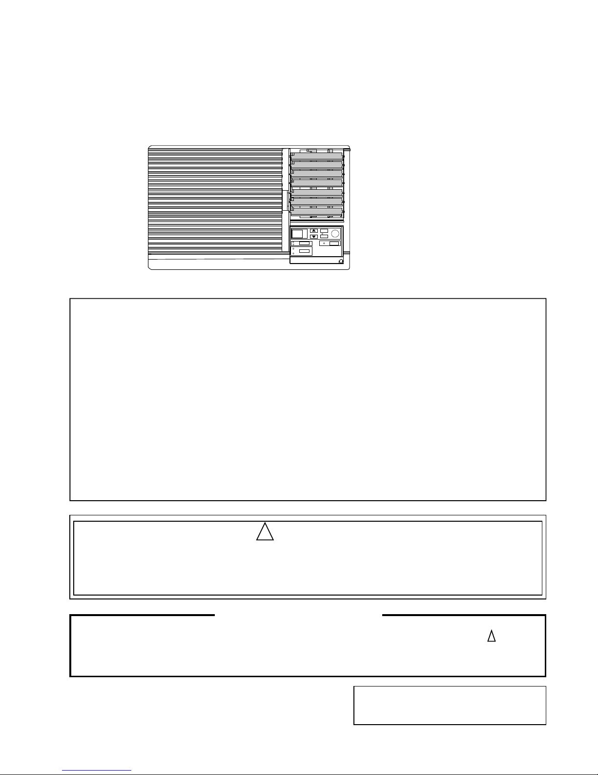
CW-XC51LE
2001 PT. National Gobel Air Conditioner Division.
All right reserved. Unauthorized copying and
distribution is a violation of law.
This service information is desidned for experienced repair technician only and is not designed for use by the general public.
It does not contain warnings or cautions to advise non-technical individuals of potential dangers in attempting to service a
product. Product powered by electricity should be serviced or repaired only by experienced professional technicians. Any
attempt to service or repair the product or product deal with in this service information by anyone else could result in serious
injury or death.
! WARNING
Specification
Model CW-XC51LE
Phase Double
Voltage 220 V
Frequency 50 Hz
Cooling Capacity 1.47 kW
5000 Btu/h
Running Current 2.1 A
Input Power 440 Watt
EER 11.1 Btu/W.h
Starting Current
Compressor Output
Fan Motor Output
Moisture Removal 0.9 Ltr/h
Noise Level Indoor High 46 dB
Low 41 dB
Outdoor High 50 dB
Low 47 dB
Air Circulation 5.1 m3/min
Dimension Height : 340 mm
Width : 525 mm
Depth : 610 mm
Net Weight 29 Kg
Gross weight 31 Kg
Refrigerant (R-22) 330 g
Note : Specification are subject to change
without notice, for further improvement.
There are special components used in this equipment which are important for safety. These parts are marked by ! in the
Schematic Diagrams, Circuit Board Diagrams, Exploded Views and Replacement Part List. It is essential that these critical parts
should be replaced with the manufacturer’s parts to prevent shock, fire or other hazards. Do not modify the original design
without permission of the manufacturer.
IMPORTANT SAFETY NOTICE
Panasonic
PanasonicPanasonic
Panasonic
PanasonicPanasonic
PanasonicPanasonic
Panasonic
- 1 -

CONTENTS
1 Functions ........................................................... 2
2 Refrigerant Cycle diagram ............................... 4
3 Block Diagram ................................................... 4
4 Wiring Diagram .................................................. 5
5 Air Conditioner Performance Evaluation ....... 5
6 Troubleshooting Guide ..................................... 6
7 Operation Details ............................................... 7
8 Operating instructions ..................................... 10
9 Air ConditionerInstallation ............................. 15
10 Care and Maintenance ................................. 17
11 Service Information ....................................... 18
12 Exploded View .............................................. 19
13 Replacement Part List .................................. 20
14 Electronic Part List ........................................ 21
15 Electronic Circuit / Indicator Complete ...... 21
16 Electronic Circuit / Main ............................... 22
17 Technical Data .............................................. 22
18 Electronic Circuit Diagram ........................... 23
1 Functions
1.1 Remote Control
OPERATION
TEMP/TIMER
TIMER
SET/
CANCEL
MODE JET MODE
FAN SPEED
Panasonic
Signal Transmitter
Operation OFF/ON
Operation Mode Selection
Fan Speed Selection
Jet Mode Operation OFF/ON
OPERA-
TION
FAN
SPEED
JET
MODE
• High Fan Speed or Low Fan Speed
• Jet Mode operation for fast cooling
MODE
• Cooling Operation Mode or Fan Operation
Mode
TIIMER
• To set delay OFF Timer.
TEMP/
TIMER
• Cooling Operation Mode
- Temperature Setting ( 16oC ~ 30oC )
SET/
CANCEL
• To start delay OFF or cancelation
Timer Operation Setting
Room Temperature and Timer Setting
Delay OFF Timer OFF/ON
• Timer Setting
- Timer Setting ( 1 ~ 12 hours )
- 2 -
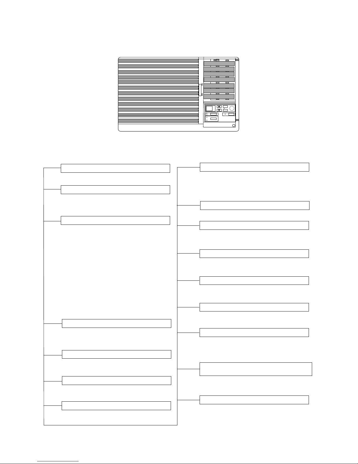
1.1 Main Unit
Operation OFF/ON
Remote Control signal Receiving Sound
Operation Indicator Light (LED’S)
OPERA-
TION
• Can be enable/disable by pressing down
Operation OFF/ON button for 10 seconds.
• MODE
COOL (Green)
FAN (Orange)
Lights up in Cooling
Mode Operation.
Lights up in Fan Mode
Operation.
• FAN SPEED
HIGH (Orange)
MED (Orange)
LOW (Orange)
Lights up in High Fan
Speed Operation.
Lights up in Medium
Fan Speed Operation.
Lights up in Low fan
Speed Operation.
• TIMER
(Orange)
Lights up in Timer
Setting.
• JET MODE
(Orange)
Lights up in Jet Mode
Operation.
Operation Mode Selection
Fan Speed Selection
Jet Mode Operation OFF/ON
• Jet Mode operation for fast cooling
FAN
SPEED
JET
MODE
• High Fan Speed or Low Fan Speed
MODE
• Cooling Operation Mode or Fan Operation
Mode
TIIMER
• To set delay OFF Timer.
Timer Operation Setting
Room Temperature and Timer Setting
TEMP/
TIMER
• Cooling Operation Mode
- Temperature Setting ( 16oC ~ 30oC )
• Timer Setting
- Timer Setting ( 1 ~ 12 hours )
SET/
CANCEL
• To start delay OFF or cancelation
Delay OFF Timer OFF/ON
Random Auto Restart Control
• Random auto restart after power failure at
previous setting mode.
Freeze Prevention Control
• Freeze prevention control for the Evaporator. (Cooling Operation Only)
Starting Current Control
• Fan Motor is delayed for 1.6 seconds
when Compressors starts simultaneously.
Time Delay safety Control
• Restarting is inhibited for approximately 3
minutes.
60 Secs. Forced Operation Control
• Once the compressor is activated, it does
not stop within the first 60 seconds.
However, it stops immediately with
remote control stop signal.
Compressor Reverse Rotation Protection
Control.
• To protect compressor from reverse
rotation when there is an instantaneous
power failure.
Over Load Protector
• Overload protector will trip to protect the
compressor when it is overheated.
Panasonic
- 3-

2 Refrigeration Cycle
2.1 CW-XC51LE
3 Block Diagram
3.1 CW-XC51LE
capillary tube
INDOOR SIDE
OUTDOOR SIDE
CONDENSOR
Intake air
sensor
COMPRESSOR
EVAPORATOR
Overload
Protector
Indicates the electronic control unit.
“C” Indicates the number of core wires. (Example : 7C = 7 core wires)
ZNR1
Transformer
Double Phase
AC 220V
50 Hz
Electronic Controller
RY-PWR
Thermal Fuse
(113oC)
Fuse (3.15A)
RY-H
RY-L
Indicator
Complite
10 C
Fan
Motor
Comp.
7 C
4 C
Sensor
Wireless Remote
Control Transmitter
- 4 -

4 Wiring Diagram
4.1 CW-XC51LE
POWER SUPPLY
CORD 1φ
, 50Hz 220V
BLUE
YELLOW/GREEN
CAPACITOR
COM PRESSOR
RED
BLUE
BROWN
R S
C
RED
RED
OLP
YELLOW
YELLOW
TRANSFORMER
BLACK T1 (BLK)
BLACK T2 (BLK)
CN-T(WHT)
FUSE
ZNR
BLUE
RED
WHITE
C-FM
(RED)
AC
(WHT)
CN-DISP1 (WHT)
CN-DISP1 (WHT)
CN-DISP2 (WHT)
CN-DISP2 (WHT)
RY-H
RY-L
C C
CN-FM
(GRN)
7 5 3 1
YELLOW
ORANGE
RED
BLUE
YELLOW/GREEN
FAN MOTOR
CN-TH(YLW)
1 2 3 4
SENSOR (INTAKE.TEMP)
YELLOW
BLUE
RED
TRADE MARK
COMPRESSOR TERMINAL
10 9 8 7 6 5 4 3 2 1
w w w w w w w w w w w w w w w w w
7 6 5 4 3 2 1
RY-PWR
P L
ELECTRONIC CONTROLLER
(RECEIVER AND DISPLAY)
10 9 8 7 6 5 4 3 2 1
7 6 5 4 3 2 1
WIRELESS
REMOTE CONTROL
REMARKS
WHT : WHITE
YLW : YELLOW
BLK : BLACK
GRN : GREEN
5 Air Conditioner Performance Evaluation
Suction & Discharge Air
Temperature Difference
- 8 C and over
- 8 C and over
- Under 8oC
- Under 8oC
- Under 8oC
Current
- As specified.
- Higher than specified.
- Higher than specified.
- Lower than specified.
- Higher than specified by 50%
Determination
- Nothing wrong.
- Nothing wrong, outdoor
temperature is too high, heat
radiation is not efficient.
- something is preventing heat
radiation.
- leakage of refrigerant or
refrigerant systems is blocked.
- Compressor defect.
Remedy
- None
- Improve heat radiation.
- Excessive amount of
refrigerant.
- Improve heat radiation.
- Locate and repair leak.
- Flush refrigeration cycle.
- Replace the compressor.
- 5 -

- 6 -
6 Troubleshooting Guide
Warning :
Disconnect unit from electrical power supply before making any electrical checks. Discharge the capacitor before checking it.
Check
1. Supply Voltage.
2. Fuse box or Circuit
Breaker.
3. Power cord or wiring
harness.
4. Temp. Setting.
1. Objects around fan.
2. Resistance between
wires.
3. Capacitor Fan Motor.
1. Temperature setting.
2. Resistance between
terminal and the
compressor body.
3. Resistance between
terminals.
4.
Overload Protector (OLP)
.
5.
Capacitor Compressor.
1. Thermostat setting.
2. Air filter dirty.
3.
Location of installation.
4.
Evaporator/Condensor coil
obstructed
.
5. Unit capacity to small or
room to big.
6. Temperature and
current difference.
1. Source of noise.
1. Unit installation.
2. Drain Tray-styrofoam
pieces blocking drain
channel.
Result
Less than 10% by rated.
Open Contacts.
Pulled loose or shorted.
Higher than room temperature.
Locked fan.
Shorted/Open circuit.
Ohm Meter doesn't deflect.
Higher than room temperature.
Shorted.
Shorted.
Infinity between terminals
.
Ohm Meter doesn't deflect.
Higher than room temperature.
Clogged or dirty.
Sunlight hitting outdoor side
obstacles.
Clogged or dirty.
Not satisfied.
Refer performance
evaluation.
Vibration.
Intermitten noise.
Tilted to inside the room.
Clogged.
Cause
Costumer restarted unit
immidiatelly without waiting
3 minutes.
Fan hitting cowling of
foreign materials.
Frozen Bearings.
Shorted or burned out.
Capacitor defect.
Winding coil touch to the body
Rare shorted or burn out.
Overload Protector (OLP) broken
.
Capacitor defect.
Restricted air circulation.
Restricted heat exchanger.
Restricted heat exchanger.
Restricted air circulation.
Leakage of refrigerant or
refrigerant systems is blocked.
Faulty installation.
Fan hitting object.
Refrigerant tubing touching
each other.
Fan splash Drain water.
Restricted run off
.
Clogged or blocked.
Remedy
Consult to an electician.
Repair open circuit.
Wait for 3 minute.
Repair or replace it.
Set it to lower.
Adjust fan position setting
.
Remove foreign materials
.
Replace wires.
Replace capacitor fan motor.
Set it to lower.
Replace compressor.
Replace compressor
terminals.
Replace Overload Protector.
Replace capacitor compressor.
Set it to lower.
Clean or replace air filter.
Consider to build an awning.
Remove obstacle or reinstall
unit.
Clean by steam cleaner.
Replace the unit with bigger
capacity.
Locate and repair leak.
Flush refrigeration cycle.
Reinstall unit or reinforce
the installation.
Adjust fan position or remove
foreign materials.
About 1/2" Clearance.
Set the drain outlet
downward, so that the
drain water can run off.
Tilt unit to out side slightly.
remove the foreign materials.
Trouble
Fan Motor and
Compressor
won't run.
Fan Motor won't
run
Compressor
won't run (Fan
motor runs).
Insufficient
Cooling
Noise
Water Dripping
7 Operation Details
7.1 Fan Mode Operation
• Fan operation only. Fan in operation according to Remote Control or main Unit ( Touch panel) Setting.
7.1.1 Manual Setting of Fan Speed
• Basic Fan Speed can be manually adjusted (Lo, Hi) by using the Fan Speed Selection Button/Pad at Remote Control or
Main Unit (Touch Control Panel).
7.2 Cooling Mode Operation
• Cooling in operation according to Remote Control or Main Unit ( Touch Control Panel) setting.
7.2.1 Time delay Safety Control ( 3 Minute)
• When the compressor is stopped by Operation Switch at the Remote Control or Main Unit (Touch Control Panel), it restart
after 3 minutes when the Operation Switch at the remote Control or Main Unit (Touch Control Panel) is turned ON.
• When the setting temperature is reached during cooling operation, the compresor stops and it will not startfor 3 minutes.
• Protection of compressor to balance the pressure in the refrigeration cycle for 3 minutes.
7.2.2 7 minutes Time Saved Control
• The compressor will start automatically if it has stopped for 7 minutes even if the room temperature is between the
compressor On temperature and OFF temperature.
7.2.3 Starting Current Control
• When the compressor and fan motor are simultaneously started, the fan motor will operate 1.6 second later.
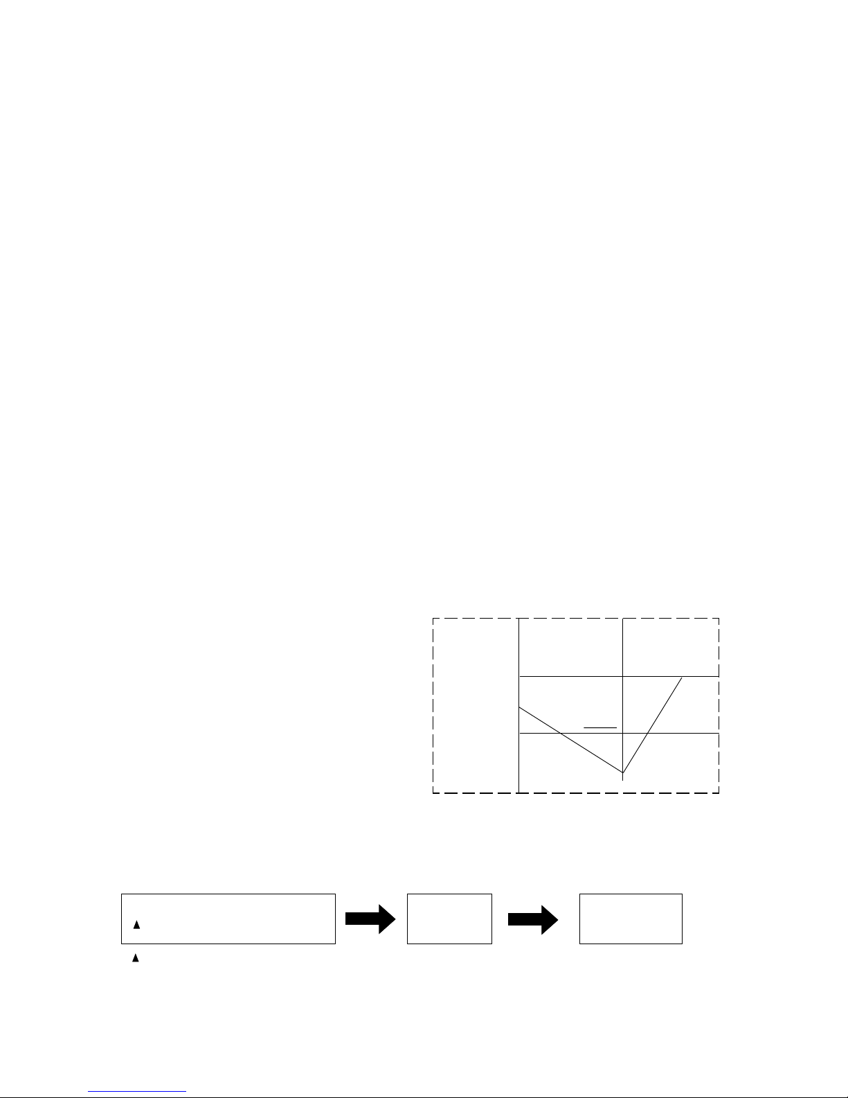
7.2.4 Freeze Prevention Control
If the temperature of the indoor heat exchanger falls continuously below 1°C for 3 minute or more, the compressor turns off to protect the heat exchanger from freezing.
The fan spee setting remains the same.
Compressor restarts when the heat exchanger temperature rises to 12°C (Recovery).
* 3 Minutes waiting of Time Delay Safety control is
valid for Cooling Operation.
7.2.5 Compressor Reverse Rotation Protection Control
• If the compressor is operating continuously for 5 minutes or longer and the temperature difference between intake air
and heat exchanger is - 15°C for 2 minutes, compressor will stop and restart automatically ( Time Delay Safety Control
is valid).
Indoor Heat
Exchanger
Temperature
(°C)
Compressor OFF
Recovery
12
1
3 min
Compressor start for ≤ 5 Minutes
T ≤ -15° C for 2 Minutes
Compressor
OFF
Compressor
restarts (3 minutes
waiting)
T = Intake air temperature - Indoor heat exchanger temperature.
This is to protect reverse rotation of the copressor when there is an instantaneous power failure.
- 7 -

7.3 Jet Mode Operation
7.2.6 Cooling Operation Time Diagram
• This Operation automatically will be running under High Fan speed, even if the LED shown the Low Fan Speed.
• Purpose of this operation is to cool down room temperature at faster speed compare to normal operation.
• When Jet Mode button is pressed, target temperature is shifted -3
o
C from the previous setting, for remote control setting from 19oC to
16oC, setting temperature shifted only to 16oC, the minimum setting temperature.
Operation LED
Fan
Compressor
Basic Time
Intake
Temperature
1.5oC
ON
OFF
Set
Temperature
3’
7’ 3’
60’
7’
60’
Operation
Stop
a b c d e f g h i j k l
< Description of operation >
b - c : Time Delay Safety Control ( waiting for 3 minutes).
d - e : 7 Minutes Time Saved Control.
g - h : 60 sec. forcible operation
• Jet Mode operation will stop with the following condition :
- Jet Mode button is pressed again.
- Jet Mode operation has run for 15 minutes
- Stopped by OFF/ON switch
- Timer OFF activates.
7.4 Random Auto Restart Control
• Restart time is decided randomly with 5 parameters :
- Intake air temperature.
- Setting temperature
- Fan speed
- Indoor heat exchanger temperature.
• If there is a power failure, operation will be automatically restarted after 3 to 4 minutes when the power is resumed. It will start with
previous operation mode (Time Delay Safety Control is Valid). as the operation was not stopped by Remote Control or main Unit (Touch
Control Panel).
• Auto Restart Control is not available when Timer is set.
• If Jet Mode is set during power failure, then after power resume, Jet Mode will not start automatically with previous operation mode.
• The control can be omitted by opening jumper JX1 on Printed Circuit Main Board.
- 8 -
 Loading...