

Page 1
Room Air Conditioner
O
F
F
/
O
N
O
P
E
R
A
T
I
O
N
T
E
M
P
/
T
I
M
E
R
C
O
O
L
F
A
N
H
I
G
H
M
E
D
L
O
W
M
O
D
E
F
A
N
S
P
E
E
D
S
E
T
T
I
M
E
R
S
E
T
/
C
A
N
C
E
L
h
r
°
F
A
I
R
S
W
I
N
G
E
C
O
N
O
M
Y
W
ire
le
s
s
R
e
m
o
t
e
C
o
n
t
r
o
l
C
L
O
S
E
V
E
N
T
O
P
E
N
INSTALLATION AND
OPERATING INSTRUCTIONS
Model CW-XC100AU
CW-XC120AU
OPERATION
TEMP/TIMER
SET/
TIMER
CANCEL
MODE
ECONOMY
FAN SPEED
AIR SWING
Panasonic
Please read these operating instructions thoroughly before
using your air conditioner and keep them for future reference.
For assistance, please call: 1-800-211-PANA (7262) or send e-mail to
consumerproducts@panasonic.com or refer to www.panasonic.com
ENGLISH
ESPAÑOL
F563181
Page 2
Thank you for purchasing a Panasonic product.
Gracias por comprar un producto Panasonic.
This Panasonic Room Air Conditioner has been designed for maximum energy efficiency and minimal noise while
keeping your room comfortably cool.
Este Acondicionador De Aire Panasonic ha sido diseñado para mantener la habitación a una temperatura
comfortable con máxima eficiencia de energia y mínimo ruido.
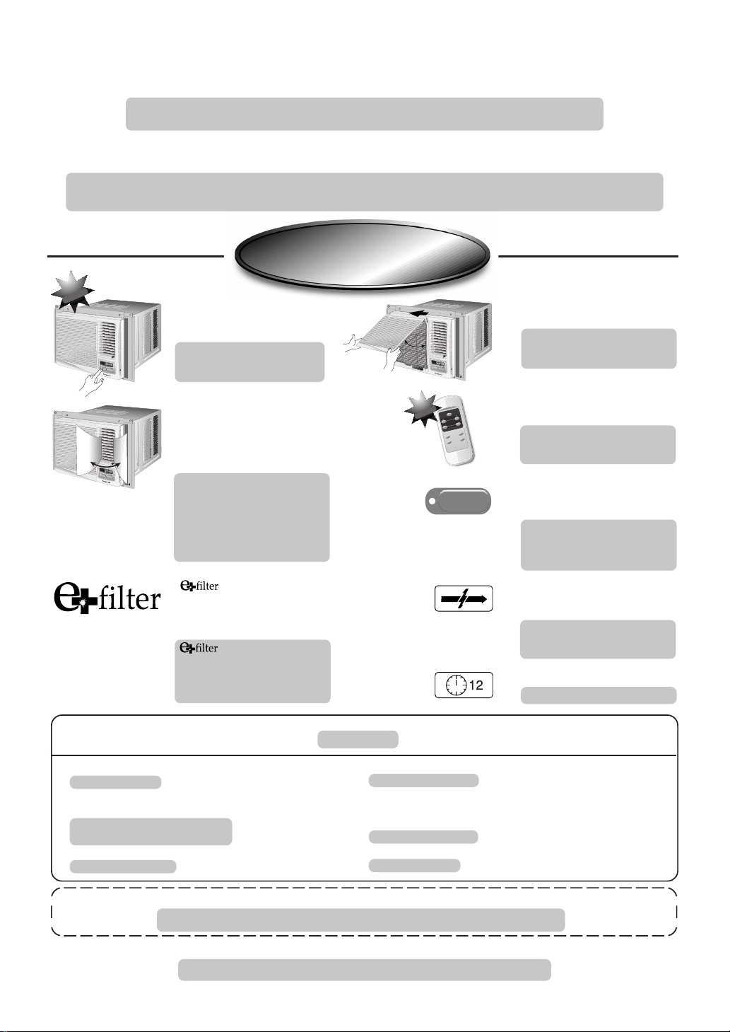
FEATURES
FEATURES
CARACTERÍSTICAS
CARACTERÍSTICAS
!
W
E
!
N
O
V
E
U
N
☛
TOUCH CONTROL PANEL
It comes with the added advantage
of easy touch pad selection for your
convenience.
C
L
O
S
E
V
E
N
T
O
P
E
N
°
F
T
I
M
E
R
O
T
P
E
E
M
R
A
P
T
/
T
I
O
I
M
N
E
hr
R
S
E
T
S
E
O
T
F
/
F
/
O
C
N
C
A
N
O
C
O
E
L
L
F
A
M
N
O
D
E
A
I
R
S
W
I
N
G
H
I
G
H
E
C
O
N
O
M
Y
M
E
D
F
A
N
S
P
E
E
L
D
O
W
W
i
r
e
l
e
R
s
e
s
m
o
t
e
C
o
n
t
r
o
l
TABLERO DE INSTRUMENTOS
Ofrece la ventaja de una selección
facíl para su comodidad.
☛
AIR SWING
The air circulation vanes swing from
side to side to direct air evenly in the
room when switched on. When the
C
L
O
S
E
V
E
N
T
O
P
E
N
°
F
T
I
M
E
R
O
T
P
E
E
M
R
A
P
T
/
T
I
O
I
M
N
E
h
R
r
S
E
T
S
E
O
T
F
/
F
/
O
C
N
C
A
N
O
C
O
E
L
L
F
A
M
N
O
D
E
A
I
R
S
W
I
N
G
H
I
G
H
E
C
O
N
O
M
Y
M
E
D
F
A
N
S
P
E
E
L
D
O
W
W
i
r
e
l
e
R
s
e
s
m
o
t
e
C
o
n
t
r
o
l
desired fixed air direction is obtained,
you can turn the air swing off.
ROTADO DEL AIRE
El balanceo de las veletas de la
circulación del aire de lado para dirigir
!
W
E
N
O
V
E
U
N
C
L
O
S
E
V
E
N
T
O
P
E
N
°
F
T
I
M
E
R
O
T
P
E
E
M
R
P
A
/
T
T
I
I
O
M
N
E
h
R
r
S
E
T
S
E
O
T
F
/
F
/
O
C
N
A
C
N
O
C
O
E
L
L
F
M
A
N
O
D
E
A
I
R
S
W
I
N
G
H
I
G
H
E
C
O
N
O
M
Y
M
E
D
F
A
N
S
P
E
E
D
L
O
W
W
i
r
e
l
e
s
R
s
e
m
o
t
e
C
o
n
t
r
o
l
!
N
IO
T
A
R
E
P
O
R
E
M
I
/T
P
M
E
T
/
T
E
S
L
E
C
N
A
C
R
E
IM
T
Y
M
O
N
O
C
E
E
D
O
M
D
E
E
P
S
N
A
F
G
IN
W
S
IR
A
c
i
n
o
s
a
n
a
P
ECONOMY
regularmente el aire en la habitación
cuando se enciende. Cuando desea
fijar la dirección del aire, tu puedes
hacer girar el rotado del aire.
☛
REMOVABLE FRONT INTAKE
GRILLE
For quick and easy cleaning.
QUITE LA REJILLA FRONTAL
DE LA TOMA DE AIRE
Para rápida y fácil limpieza.
☛
WIRELESS REMOTE CONTROL
The remote control is designed to be
user-friendly.
TELECONTROL SIN CABLE
El telecontrol es diseñado para que
sea amistosa.
☛
ECONOMY MODE
One-touch power saving operation for
economical cooling.
MODO ECONOMY
Operación de ahorro de electricidad
de un toque para refrigeración
económica.
☛
The e+filter keeps room air cleaner
by attracting, and trapping tiny particles
that would pass through ordinary
filters.
El filtro mantiene el aire ambiente más
limpio al atraer y atrapar pequeñas
partículas que pasan a través de filtros
normales.
REFERENCE
REFERENCIA
Model Number : ___________________________________________
Número del modelo:
Serial Number : ___________________________________________
(Located on the side of unit)
Número de serie:
(Localizado en el costado de la unidad)
Dealer's Name : ___________________________________________
Nombre del distribuidor:
Please staple your purchase receipt here for future reference.
Por favor Pegue acá su recibo de compra para un referencia futuro.
© 2000 Matsushita Electrical Co., Ltd. All Right Reserved.
© 2000 Matsushita Electrical Co., Ltd. Derechos Reservados.
☛
RANDOM AUTO RESTART
Automatically restarts the unit after
power failure.
AL AZAR DE AUTOARRANQUE
Arranca automáticamente el aparato
después de un apagón.
☛
12-HOUR OFF TIMER
TEMPORIZADOR DE 12 HORAS
Dealer's Address : __________________________________________
Nombre del comerciante:
Dealer's Tel : ______________________________________________
Teléfono del comerciante:
Date of Purchase : _________________________________________
Fecha de adquisicion:
Page 3
CONTENTS
CONTENTS
CONTENIDO
CONTENIDO
■ SAFETY PRECAUTIONS........................................................................................ 2 ~ 5
■ PRECAUCIONES DE SEGURIDAD
■ AIR CONDITIONER INSTALLATION ................................................................ 6 ~ 11
■ INSTALACIÓN DEL ACONDICIONADOR DE AIRE
■ PART IDENTIFICATION..................................................................................... 12 ~ 14
■ IDENTIFICACIÓN DE LOS COMPONENTES
■ PREPARATIONS BEFORE OPERATION .................................................................. 15
■ PREPARACIÓN ANTES DEL FUNCIONAMIENTO
■ AIR CONDITIONER OPERATION .................................................................... 16 ~ 20
■ OPERACIÓN DEL ACONDICIONADOR DE AIRE
■ HELPFUL INFORMATION ......................................................................................... 21
■ INFORMACIÓN ÚTIL
■ ENERGY SAVING HINTS ................................................................................... 22 ~ 23
■ CONSEJOS DE AHORRAMIENTO DE ENERGÍA
■ CARE AND MAINTENANCE ............................................................................. 24 ~ 26
■ CUIDADO Y MANTENIMIENTO
■ PRODUCT SPECIFICATIONS ................................................................................... 27
■ ESPECIFICACIONES DEL PRODUCTO
■ BEFORE CALLING FOR SERVICE .................................................................... 28 ~ 29
■ ANTES DE LLAMAR PARA MANTENIMIENTO
PRODUCT
SPECIFICATION
1
Page 4
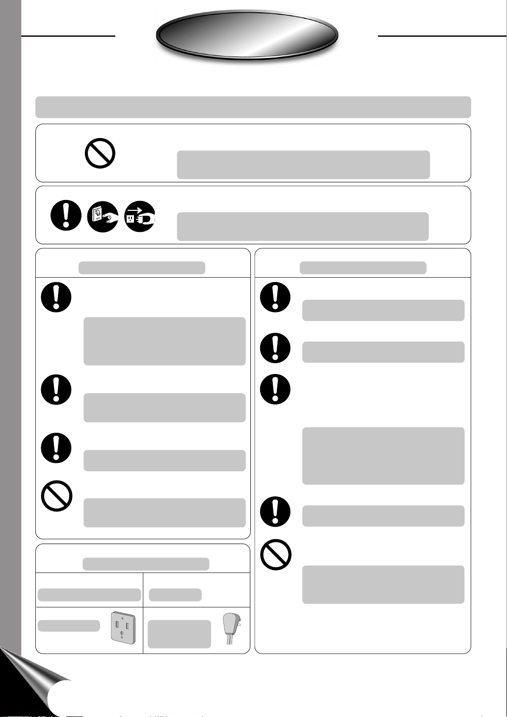
SAFETY PRECAUTIONS
SAFETY PRECAUTIONS
PRECAUCIONES DE SEGURIDAD
PRECAUCIONES DE SEGURIDAD
• Please observe the following safety precautions when using your air conditioner.
Failure or negligence in observing these safety precautions could cause fire, electrical shock or personal injury.
• Por favor observe las siguientes precauciones de seguridad cuando use su acondicionador de aire.
Si usted no observa las precauciones, puede resultar en incendio, choque eléctrico o heridas personales.
This symbol (with a white background) denotes an action that is
PROHIBITED.
Este símbolo (con un fondo blanco) denota una acción que
es PROHIBIDO.
These symbols (with a blue background) denote actions that are
COMPULSORY.
Estos símbolos (con fondo azul) denotan acciones que son
OBLIGATORIAS.
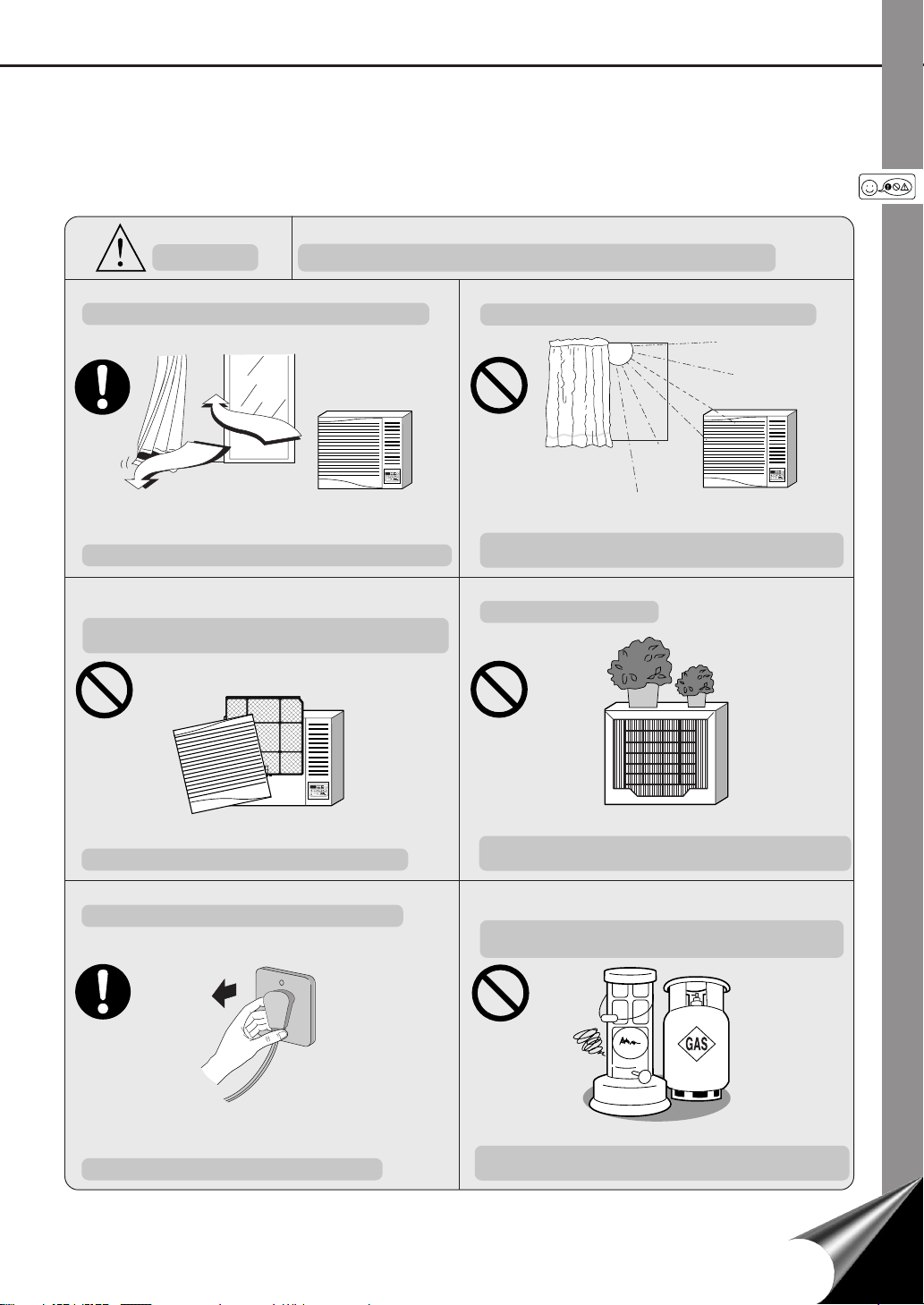
Installation Precautions
Precauciones de Instalación
• Due to the weight of this product, we recommend that you have a helper to assist in the
installation. To avoid injury, use the proper
method of lifting. Avoid any sharp edges.
• Debido a que este producto es muy pesado, le
recomendamos que tenga un asistente para
ayudarlo en la instalación. Para evitar lesiones,
use un modo propio para levantarlo. Aléjese de
los bordes afilados.
• Make sure the window frame to be used can
properly support this product.
• Asegúrese que el marco de la ventana que se
usará puede soportar apropiadamente este
producto.
• This product must be installed in accordance
with all local codes and ordinances.
• Este producto debe ser instalado de acuerdo
con las leyes y regulaciones locales.
• Do not install the unit in places where
inflammable gas, fumes or soot may be generated.
• No instale la unidad cerca de lugares, donde
puedan ser producidos gases inflamables,
emanaciones de humo u hollín.
Operation Precautions
Precauciones de Operación
• Operate your air conditioner from a stable
115 volt AC supply.
• Haga funcionar su acondicionador de aire desde
una fuente de alimentación de CA de 115 voltios.
• Plug into a separate 15 amp grounded outlet only.
• Enchúfelo sólo en un tomacorriente separado
de 15 amp con conexión a tierra.
• Use of extension cords
Avoid using extension cords. If there are no
alternatives, ensure that the cord is a UL listed
3-wire grounding type, rated 125 volts with a
minimum current-carrying rating of 15 amps,
number 14 or heavier wire.
• Utilización de cables de extensión
No use cables de extensión. Si no existiera otra
posibilidad, debería ser un cable de 3 alambres
con conexión a tierra de tipo UL, de 125 voltios
con un amperaje mínimo de 15 amp, de alambre
número 14 o mayor.
• Use a 15 amp time delay fuse or a circuit breaker.
• Use un fusible de retardo de 15 amp o un
interruptor automático.
• Do not switch off by unplugging the power plug
Power Supply
Suministro de Electricidad
Time Delay Fuse : 15 Amps
Fusible de Retardo : 15 Amp
Socket Type
Tipo de enchufe
Rated Voltage : 115V
Voltaje :115V
Line Cord Plug
Cable de
Alimentación de
Corriente
while it is operating. Press the OFF/ON pad to
“OFF” before unplugging.
• No desconecte desenchufando el enchufe de
alimentación mientras esté funcionando.
Presione el botón OFF/ON para desconectar
antes de desenchufar.
2
Page 5

OPERATION PRECAUTIONS
COOL
MODE
OFF/ON
OPERATION
TEMP/TIMER SET
TIMER
hr
F
ECONOMY
FAN SPEED
SET/
CANCEL
FAN
HIGH
MED
LOW
AIR SWING
PRECAUCIONES DE OPERACIÓN
WARNING
ADVERTENCIA
This sign warns of risk of death or serious injury.
Esta señal indica riesgo de peligro de muerte o lesiones serias.
• Do not modify the length of the power cord or use an extension cord.
• No modifique el largo de cable de suministro de poder ni use cables
de extensión.
It could cause electrical shock or fire.
Podría causar una descarga eléctrica.
• Do not turn on the unit by inserting the power plug.
Do not switch off the unit by pulling out the power plug.
• No opere la unidad insertando el enchufe principal.
No apague la unidad sacando el enchufe principal.
It could cause electrical shock or fire.
Podría causar una descarga eléctrica.
• Do not touch or operate with wet hands.
Do not modify or damage the cord.
• No toque ni opere con las manos mojadas. No modifique o dañe el
cable eléctrico.
It could cause electrical shock or fire.
Podría causar una descarga eléctrica.
• Plug in properly before operating and use a specified power cord.
• Enchufe adecuadamente antes de operar y utilice un cable
especificado.
It could cause electrical shock or fire.
Podría causar una descarga eléctrica.
• If abnormal conditions (burnt smell, etc) occur, switch off and remove
the power plug.
• Si detecta una situación anormal (por ejemplo, olor a quemado), pare
• Avoid an extended period of direct airflow.
• Evite estar un largo tiempo expuesto directamente a la corriente de
aire.
el acondicionador de aire y quite el enchufe principal.
OPERATION
TIMER
¡F
TEMP/TIMER SET
OFF/ON
hr
SET/
CANCEL
COOL
ECONOMY
AIR SWING
MODE
FAN
HIGH
FAN SPEED
MED
Switch off the breaker and remove the power plug.
Apague el interruptor y quite el enchufe principal.
LOW
The heat generated could cause electrical shock or fire.
Please consult an authorized dealer or servicenter.
El calor generado podría causar una descarga electrica o un incendio.
Por favor consulte a su comerciante autorizado o servicio técnico.
• Do not insert sticks, fingers or any other object into the unit.
• No inserte palos, dedos o cualquier otra clase de objeto en la unidad.
OPERATION
TIMER
¡F
TEMP/TIMER SET
OFF/ON
hr
SET/
CANCEL
COOL
ECONOMY
AIR SWING
MODE
FAN
HIGH
FAN SPEED
MED
LOW
It could lead to health problems.
Podría llevar a problemas de salud.
• Do not try to repair the unit yourself.
• No intente reparar la unidad usted mismo.
It could lead to fire or cause an electrical shock.
It could lead to physical injury as well as damage to the unit.
Podría causar alguna herida física asi como también dañar la unidad.
Please call an authorized dealer or servicenter.
Podría llevar a causar un incendio o una descarga eléctrica.
Por favor consulte a su comerciante autorizado o servicio técnico.
OPERATION
TIMER
¡F
TEMP/TIMER SET
OFF/ON
hr
SET/
CANCEL
COOL
ECONOMY
AIR SWING
MODE
FAN
HIGH
FAN SPEED
MED
LOW
3
Page 6

SAFETY PRECAUTIONS
COOL
MODE
OFF/ON
OPERATION
TEMP/TIMER SET
TIMER
hr
¡F
ECONOMY
FAN SPEED
SET/
CANCEL
FAN
HIGH
MED
LOW
AIR SWING
COOL
MODE
OFF/ON
OPERATION
TEMP/TIMER SET
TIMER
hr
¡F
ECONOMY
FAN SPEED
SET/
CANCEL
FAN
HIGH
MED
LOW
AIR SWING
SAFETY PRECAUTIONS
PRECAUCIONES DE SEGURIDAD
PRECAUCIONES DE SEGURIDAD
OPERATION PRECAUTIONS
PRECAUCIONES DE OPERACIÓN
CAUTION
CUIDADO
This sign warns of injury or damage to property.
Esta señal indica peligro de lesiones o daño a la propiedad.
• Switch off the breaker and remove the power plug from the socket if
the unit will not be operated for a long period, such as while on vacation.
• Apague el interruptor y quite el enchufe principal, si no utilizará la
unidad por un largo tiempo, como durante las vacaciones.
OPERATION
TIMER
Switch off the breaker and remove the power plug.
Apague el interruptor y quite el enchufe principal.
F
TEMP/TIMER SET
OFF/ON
hr
SET/
CANCEL
COOL
ECONOMY
AIR SWING
MODE
FAN
HIGH
FAN SPEED
MED
LOW
Dust accumulated on the power plug pin may cause over-heating and fire.
El polvo acumulado en el enchufe principal puede causar sobre calentamiento e
incendio.
• Do not remove the power plug by pulling the cord.
• No quite el enchufe principal de alimentación tirando del cable.
• Do not use the unit for any other purpose, than its intended use.
• No utilice la unidad para cualquier otro propósito que el destinado.
OPERATION
TIMER
F
TEMP/TIMER SET
OFF/ON
hr
SET/
CANCEL
COOL
ECONOMY
AIR SWING
MODE
FAN
HIGH
FAN SPEED
MED
LOW
Do not use for cooling or preservation purposes. It will affect food quality.
No use para fines de enfriar o preservar alimentos. Podría afectar la calidad de
estos.
• Do not block the air intake and outlet vanes.
• No bloquee la salida ni entrada de aire.
Hold the power plug when disconnecting the power plug from the wall outlet.
Sujete el enchufe principal cuando desconecte el enchufe principal de la salida
de la pared.
• Pay attention to any wear damage on the unit caused by extensive
usage.
Cooling performance will be affected.
El proceso de enfriamiento será afectado.
• Do not splash or direct water at the unit.
• No moje la unidad ni exponga al agua.
• Ponga atención a cualquier daño por desgaste en la unidad causado
por un uso extensivo.
OPERATION
TIMER
¡F
TEMP/TIMER SET
OFF/ON
hr
SET/
CANCEL
COOL
ECONOMY
AIR SWING
MODE
FAN
HIGH
FAN SPEED
MED
LOW
Ensure that the necessary repairs are carried out.
Asegúrese de que los reparos necesarios sean llevados a cabo.
4
It could cause electrical shock.
Podría causar una descarga eléctrica.
Page 7
CAUTION
COOL
MODE
OFF/ON
OPERATION
TEMP/TIMER SET
TIMER
hr
¡F
ECONOMY
FAN SPEED
SET/
CANCEL
FAN
HIGH
MED
LOW
AIR SWING
CUIDADO
This sign warns of injury or damage to property.
Esta señal indica peligro de lesiones o daño a la propiedad.
• Ventilate the room occasionally where the unit is installed.
• Ventile ocasionalmente el cuarto donde la unidad esta instalada.
OPERATION
TIMER
¡F
TEMP/TIMER SET
OFF/ON
hr
SET/
CANCEL
COOL
ECONOMY
AIR SWING
MODE
FAN
HIGH
FAN SPEED
MED
LOW
Since windows are kept closed, it does good to open them periodically to ventilate
the room.
Cuando las ventanas son mantenidas cerradas, es bueno abrirlas para ventilar el cuarto.
• Do not operate the unit without the air filter or when the front intake
grille has been removed.
• No opere sin el filtro de aire o cuando la rejilla frontal de toma de aire
haya sido removida.
OPERATION
TIMER
¡F
TEMP/TIMER SET
OFF/ON
hr
SET/
CANCEL
COOL
ECONOMY
MODE
AIR SWING
FAN
HIGH
FAN SPEED
MED
LOW
• Do not expose the unit to direct sunlight during operation.
• No exponga la unidad a la luz solar, mientras esta funcionando.
Cooling performance will be affected, thus increasing power consumption.
El proceso de enfriamiento será afectado, así se incrementará el consumo de
electricidad.
• Do not place any objects on the unit.
• No coloque objetos en la unidad.
It could cause dust to accumulate on the heat exchanger.
Podría causar acumulamiento de polvo en el intercambiador de calor.
• Remove the power plug when cleaning the unit.
• Desconecte el enchufe principal cuando se limpie la unidad.
This is to prevent injury caused by the rotating fan in the unit.
Esto es para prevenir lesiones debido al ventilador de la unidad.
The object may fall off or the weight of it could cause the unit to collapse.
El objeto podría caerse o el peso del mismo podría causar un colapso en la
unidad.
• Do not operate any combustion equipment near the unit’s airflow
area.
• No coloque ningún equipo de combustible en el paso del flujo de aire
de la unidad.
Incomplete combustion due to the air flow could cause toxic gas (CO) poisoning.
La combustión deficiente debido a la corriente de aire podría causar
envenenamiento por gases tóxicos (CO).
5
Page 8

AIR CONDITIONER INSTALLATION
AIR CONDITIONER INSTALLATION
INSTALACIÓN DEL ACONDICIONADOR DE AIRE
INSTALACIÓN DEL ACONDICIONADOR DE AIRE
CAUTION
CUIDADO
Please remove the shipping blocks
fixed to the compressor and front
grille before installation.
Por favor remueva los tacos de envío
fijados en el compresor y la rejilla
frontal antes de la instalación.
Compressor
Compresor
REMOVE
REMUEVA
Shipping blocks
Tacos de envío
INSTALLATION BOX CONTENTS
CONTENIDO DE LA CAJA DE INSTALACIÓN
Window sash foam seal
Espuma de sellado de la
hoja móvil de la ventana
Type B screws
Tornillos tipo B
Panel retainer
Retenedor del panel
Type A screws
Tornillos tipo A
Type C screws
Tornillos tipo C
Panel retainer
Retenedor del panel
Top angle
Angulo
superior
Left side
expandable panel
Lado izquierdo del
panel extensible
BACK VIEW
VISTA TRASERA
Front intake grille
Rejilla frontal de la
toma de aire
Front grille
Rejilla frontal
Window sash sealing ribbon
Cinta de sellado de la hoja
móvil de la ventana
Type A screws
Tornillos tipo A
Type C screws
Tornillos tipo C
Front grille
Rejilla frontal
Sealer 50 g
(1.8 oz) (Putty)
Sellador 50 g
(1,8 oz) (Masilla)
Right side
expandable panel
Lado derecho del
panel extensible
SCREWS
FURNISHED
TORNILLOS
SUMINISTRADOS
Type Part no. Remarks Qty.
Tipo Parte no. Comentario Cantidad
XTN5D25A
A
CWH4580211
B
XTT4D10C
C
ACCESSORIES
ACCESORIOS
Type A Type B Type C
Tipo A Tipo B Tipo C
Wood Screw
Tornillo para madera
Machine Screw
Tornillo para metales
Tapping Screw
Tornillo de rosca
SUGGESTED TOOL LIST
LISTA DE HERRAMIENTAS SUGERIDAS
Medium sized screwdriver (#2 Phillips)
Destornillador mediano (Phillips No. 2)
Tape Measure
Cinta métrica
4
5
4
(4 pcs)
(4 piezas)
Pencil
Lápiz
Level
Nivel
Knife or Scissors
Cuchilla o tijeras
(5 pcs)
(5 piezas)
(4 pcs)
(4 piezas)
Note : Check that none of the
accessories are missing.
Nota : Compruebe que no falte
ninguno de los accesorios.
6
Page 9
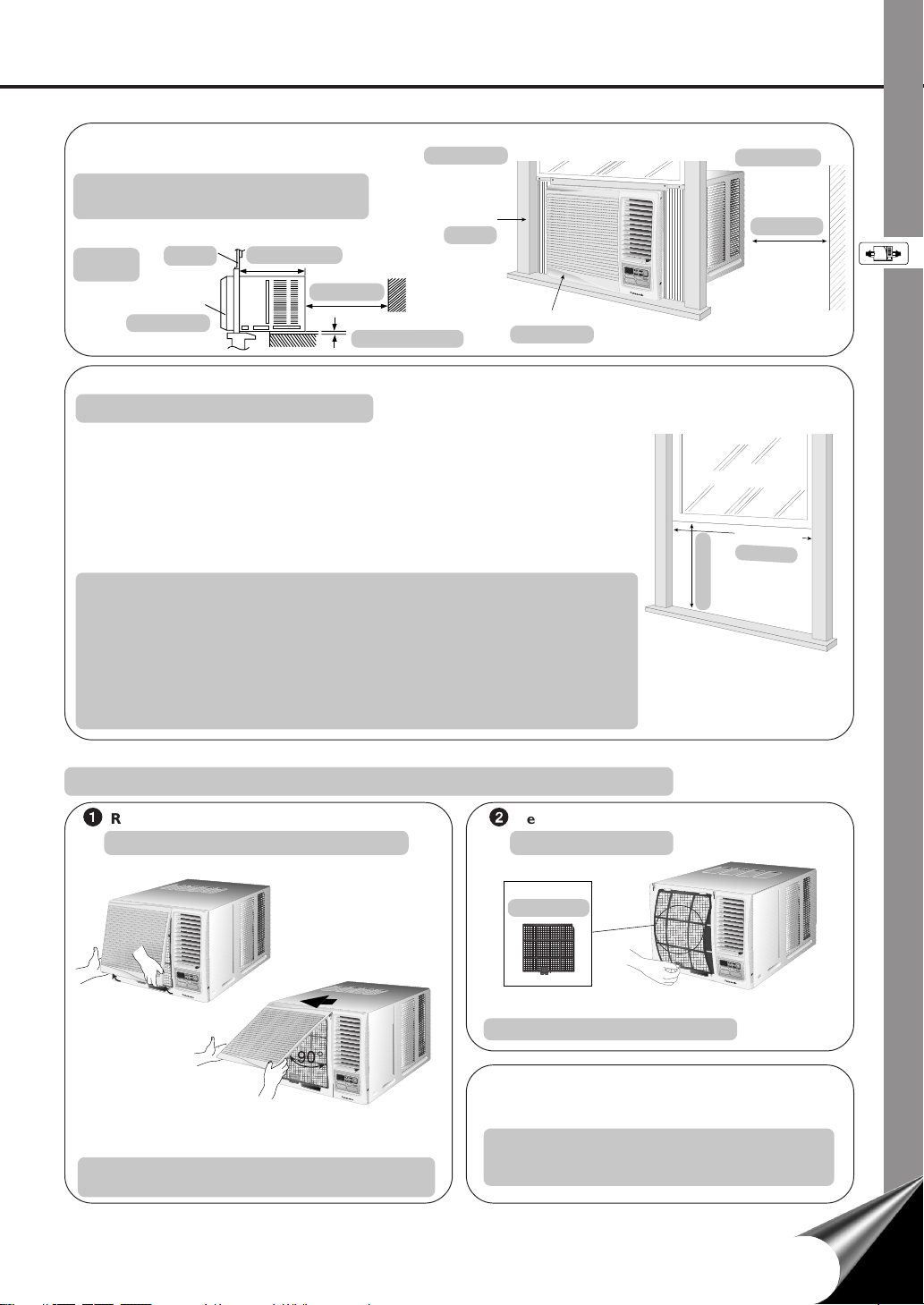
SELECT THE BEST LOCATION
(Single or Double hung window)
Indoor side
Lado interior
ELIJA LA MEJOR UBICACIÓN
(Ventana de guillotina simple o doble)
3
19–
/
SIDE VIEW
VISTA
LATERAL
Window
Ventana
Front grille
Rejilla frontal
3
/16 pulgadas
19–
16
inches
12 inches
12 pulgadas
More than 4 inches
Más de 4 pulgadas
Window
Ventana
Front grille
Rejilla frontal
WINDOW REQUIREMENTS
REQUISITOS DE LA VENTANA
• Hot sun rays hitting the outside surface of the cabinet will create considerable heat
load. If the outside of the cabinet is exposed to direct sunlight, consider building an
awning to shade the cabinet while providing ample area for the heated air to be
exhausted from the condenser (both sides) and the top.
This unit is designed for installation in standard double hung windows.
NOTE: The unit may also be installed “through the wall”. You should, however,
observe standard carpentry practices and frame the opening without violating
local ordinances.
• Los rayos solares que tocan la superficie exterior de la caja crearán una considerable
carga de calor. Si la parte que da al exterior de la caja está bajo la luz directa del sol,
considere el construir un toldo para dar sombra pero dejando espacio suficiente para
que el aire caliente pueda ser expulsado del condensador (en ambos lados) y parte
superior.
Este aparato está diseñado para ser instalado en ventanas levadizas dobles.
NOTA: Esta unidad tambíen se puede instalar a través de la pared. En este caso, se
deberán realizar trabajos de carpintería y construir una estructura en la abertura
deacuerdo con los reglamentos locales.
Outdoor side
Lado exterior
12 inches
12 pulgadas
C
L
O
S
E
V
E
N
T
O
P
E
N
°
F
T
I
M
E
R
O
P
E
T
R
E
A
M
T
I
P
O
/
T
N
I
M
E
R
h
r
S
E
T
O
F
S
F
E
/
T
O
/
N
C
A
N
C
E
C
L
O
O
L
F
A
M
N
O
D
E
A
IR
S
W
I
N
G
H
I
E
G
C
H
O
N
O
M
Y
M
E
D
F
A
N
S
P
E
E
L
D
O
W
W
i
r
e
l
e
s
R
s
e
m
o
t
e
C
o
n
t
r
o
l
1
22
to 42-
/
8
1
22
a 42-
/
8
(minimo)
16
/
15
15-
(min)
16
/
15
15-
PREPARATION OF AIR CONDITIONER CHASSIS
PREPARACIÓN DEL CHASIS DEL ACONDICIONADOR DE AIRE
1
Remove the front intake grille
Quite la rejilla frontal de la toma de aire
C
L
O
S
E
V
E
N
T
O
P
E
N
°
F
T
I
M
E
R
O
T
P
E
E
M
R
P
A
/
T
T
I
I
O
M
N
E
h
R
r
S
E
T
S
E
O
T
F
/
F
/
O
C
N
A
C
N
O
C
E
O
L
L
F
A
M
N
O
D
E
A
I
R
S
W
I
N
G
H
I
G
H
E
C
O
N
O
M
Y
M
E
D
F
A
N
S
P
E
E
D
L
O
W
W
ir
e
le
R
s
e
s
m
o
t
e
C
o
n
t
r
o
l
C
L
O
S
E
V
E
N
T
O
P
E
N
°
F
T
I
M
E
R
O
T
P
E
E
M
R
P
A
/
T
T
I
I
O
M
N
E
h
R
r
S
E
T
S
E
O
T
F
/
F
/
O
C
N
A
C
N
O
C
E
O
L
L
F
A
M
N
O
D
E
A
I
R
S
W
I
N
G
H
I
G
H
E
C
O
N
O
M
Y
M
E
D
F
A
N
S
P
E
E
D
L
O
W
W
i
r
e
l
e
R
s
e
s
m
o
t
e
C
o
n
t
r
o
l
Pull up the front intake grille about 90° and slide it slightly
to the left to unhook the tabs.
Tire la rejilla frontal cerca de 90° y deslice un poco a la
izquierda para desenganchar la etiqueta.
2
Remove the air filter
Quite el filtro de aire
Air filter
Filtro de aire
Tilt up and pull out the air filter by the holder.
Incline y saque el filtro por el soporte.
NOTE: It is much easier, and also safer, to install the
empty cabinet into a window first and we
suggest that you follow this procedure.
NOTA: Es mucho más fácil y también más seguro
instalar primero la caja vacía en la ventana.
Nosotros sugerimos, que lo haga así.
C
L
O
S
E
V
E
N
T
O
P
E
N
°
F
T
I
M
E
R
O
T
P
E
E
M
R
A
P/T
T
I
O
IM
N
E
h
R
r
S
E
T
S
E
O
T
F
/
F
/O
C
N
A
C
N
O
C
O
E
L
L
F
A
M
N
O
D
E
A
I
R
S
W
I
N
G
H
I
G
H
E
C
O
N
O
M
Y
M
E
D
F
A
N
S
P
E
E
D
L
O
W
W
i
r
e
l
e
R
s
e
s
m
o
t
e
C
o
n
t
r
o
l
7
Page 10
AIR CONDITIONER INSTALLATION
AIR CONDITIONER INSTALLATION
INSTALACIÓN DEL ACONDICIONADOR DE AIRE
INSTALACIÓN DEL ACONDICIONADOR DE AIRE
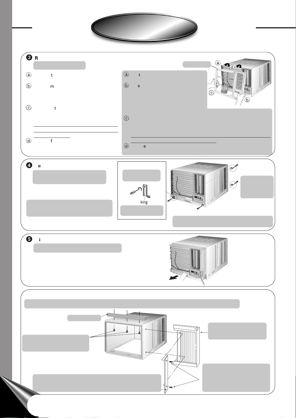
3
Remove the front grille
Quite la rejilla frontal
a
Remove the adhesive tape from all sides of
the front grille.
b
At bottom right side of the front grille, press
inward on cabinet near the power cord, and
pull the grille outward to the right until right
tab releases.
c
At the bottom left side, push inward on
cabinet and pull the grille outward to the
left to release the left tab.
Do not pull the bottom edge toward you
more than 3 inches to prevent the two top
tabs from damage.
d
Slide the front grille upwards to free the two
top tabs from slots at the top of the cabinet.
4
Remove the chassis locking bracket
Quite los soportes que cierran
el chasis
Unscrew and remove the chassis locking
brackets. Keep for later use.
Desatornille y quite los soportes que
cierran el chasis. Guardelos para futuro
uso.
Front grille
a
d
a
Quite las cintas adhesivas de los
Rejilla frontal
lados de la rejilla frontal.
b
En la parte inferior derecha de la rejilla
frontal, presione hacia dentro en el
mueble al lado del cordón de
alimentación y tire de la rejilla hacia
c
F
T
E
M
h
P
r
/
T
I
M
E
R
C
O
O
L
C
F
A
N
M
O
D
E
H
I
A
G
I
H
R
S
W
I
N
F
A
N
L
S
O
P
W
E
E
D
W
R
e
m
b
fuera, hacia la derecha, hasta
desenganchar la lengüeta derecha.
c
En el lado inferior izquierdo, presione hacia dentro en el mueble y tire
de la rejilla hacia fuera, hacia la izquierda, para desenganchar la lengüeta
izquierda.
No tire del borde inferior, hacia usted, más de 3 pulgadas para impedir
que las dos lengüetas superiores se dañen.
d
Deslice la rejilla frontal hacia arriba para liberar las dos lengüetas
superiores de las ranuras en la parte superior del mueble.
Counter clockwise.
En sentido contrario
al reloj.
Chassis locking bracket
Soportes que cierran
el chasis
¡
F
T
T
E
I
M
M
h
P
E
r
/
R
T
I
M
O
E
P
R
E
R
A
T
I
O
N
S
E
T
C
O
O
S
L
E
T
O
/
F
C
F
F
A
A
/
N
N
O
C
N
M
E
L
O
D
E
H
I
A
G
I
R
H
S
W
I
N
G
M
E
D
F
ECONOMY
A
N
L
S
O
P
W
E
E
D
W
i
r
e
l
R
e
e
s
m
s
o
t
e
C
o
n
t
r
o
l
Remove the chassis grounding screw and save for later use.
Retire el tornillo de puesta a tierra del chasis y guárdelo
para uso posterior.
Unscrew and
remove from rear
cabinet.
Destornille y
remueva desde la
parte de atrás del
caja.
T
I
M
E
R
O
P
E
R
A
T
I
O
N
S
E
T
S
E
T
O
/
F
F
A
/
N
O
C
N
E
L
G
E
C
O
N
O
M
Y
i
r
e
l
e
s
s
o
t
e
C
o
n
t
r
o
l
5
Slide the chassis out from the cabinet
Deslice el chasis hacia afuera del caja
¡
F
T
E
T
M
h
I
P
M
r
/
T
E
I
R
M
E
O
R
P
E
R
A
T
I
O
S
N
E
C
T
O
O
L
S
F
E
A
T
N
O
C
/
F
A
F
N
M
/
C
O
O
E
N
D
L
E
H
I
G
H
A
I
R
S
W
M
I
N
E
G
D
F
A
N
L
O
S
E
W
P
C
E
O
N
E
O
D
M
Y
W
ir
e
R
l
e
e
m
s
o
s
t
e
C
o
n
t
r
o
l
HOW TO ASSEMBLE THE EXPANDABLE PANELS (LEFT & RIGHT)
COMO ARMAR LOS PANELES EXPANSIBLES (IZQUIERDO Y DERECHO)
Top angle
Angulo superior
Attach the top angle to the cabinet
using screw type B (3 pcs).
Fije el ángulo superior a la caja
utilizando tornillos de tipo B
(3 piezas).
Panel retainer
(The panel retainers are packed in the folds of the expansion panels.)
Retenedor del panel
(Las placas de retención del panel están empacadas en los pliegues de
los paneles expansibles.)
8
8
Insert expandable panels to
cabinet sides as shown.
Inserte los paneles expansibles
a los costados de la caja como
se muestra.
Attach a panel retainer on the first
fold of each expansion panel and
secure panel retainers to cabinet
using screw type C (2 each).
Inserte la placa de retención del
panel dentro del primer pliegue de
cada uno de los paneles expansibles
y retenedor del panel al caja usando
los tornillos tipo C (2 cada uno).
Page 11

C
O
O
L
M
O
D
E
O
F
F
/
O
N
O
P
E
R
A
T
I
O
N
T
E
M
P
/
T
I
M
E
R
S
E
T
T
I
M
E
R
h
r
¡
F
F
A
N
S
P
E
E
D
A
I
R
S
W
I
N
G
S
E
T
/
C
A
N
C
E
L
F
A
N
H
I
G
H
M
E
D
L
O
W
E
C
O
N
O
M
Y
W
i
r
e
l
e
s
s
R
e
m
o
t
e
C
o
n
t
r
o
l
CABINET INSTALLATION
INSTALACIÓN DEL CAJA
1
Cut the “Sealing Ribbon” to the proper length, and attach it
along the bottom edge of the bottom window sash.
Corte la cinta de sellar del largo apropiado y colóquela a lo
largo de la parte inferior de la ventana de guillotina.
2
To prevent condensation water from dripping inside, the cabinet
should be installed level or very slightly tilted to the outside.
Para prevenir que el agua de condensación gotee dentro, el
caja debe ser instalada al nivel o con una muy ligera inclinación
desde adentro hacia fuera.
3
Secure the cabinet using screws.
Fije la caja usando los tornillos.
Type A screws
Tornillos tipo A
Type B screws
Tornillos tipo B
Inside of sash
Interior de la hoja móvil
Top angle
Angulo superior
Window sash sealing ribbon
Cinta de sellado de la hoja
móvil
Outside of sash
Exterior de la hoja móvil
Sealing ribbon
Cinta de sellar
Window sash
Hoja de la ventana
Window sill
Alféizar de la
ventana
Type A screws
Panel extensible
Tornillos tipo A
Expandable panel
• Expand the expandable panel fully into the grooves of the
window frame, secure the expandable panel, left, right and
top mounting frames to the bottom of the window sash
using 4 screws type A and 2 screws type B.
• Secure the cabinet using wood screws type A.
• Cut the window sash foam seal to the proper size and
seal the opening between the top of the inside window
sash and the outside window sash.
Note : If a gap exists between the unit and window sash,
you may use “Sealer” supplied with the installation
kit for a better seal.
• Expande el panel extenible completamente dentro del marco de la
ventana, asegúrelo a la parte inferior de la hoja de la ventana por la
izquierda, a la derecha y por la parte superior, usando A tornillos tipo
A y 2 tornillos del tipo B.
• Fije la caja usando tornillos para madera tipo A.
• Corte la cinta para sellar de la hoja de la ventana del tamafío correcto
y selle la abertura entre la parte superior del interior y del exterior
de la hoja de la ventana.
Nota : Si existiera un espacio entre la unidad y la hoja de la ventana,
puede usar el sellador que está dentro del paquete de instalación,
para obtener un mejor sellado.
CHASSIS INSTALLATION INTO THE CABINET
INSTALACIÓN DEL CHASIS DENTRO DE LA CAJA
1
Slide the chassis into the cabinet
Deslica el chasis dentro del caja
9
Page 12

AIR CONDITIONER INSTALLATION
C
O
O
L
M
O
D
E
O
F
F
/
O
N
O
P
E
R
A
T
I
O
N
T
E
M
P
/
T
I
M
E
R
S
E
T
T
I
M
E
R
h
r
¡
F
F
A
N
S
P
E
E
D
A
IR
S
W
IN
G
S
E
T
/
C
A
N
C
E
L
F
A
N
H
I
G
H
M
E
D
L
O
W
E
C
O
N
O
M
Y
W
i
r
e
l
e
s
s
Remote
Control
AIR CONDITIONER INSTALLATION
INSTALACIÓN DEL ACONDICIONADOR DE AIRE
INSTALACIÓN DEL ACONDICIONADOR DE AIRE
2
Reinstall the chassis locking
brackets and retighten the screws
Reinstale los soportes que cierran
el chasis y apriete bien los tornillos
Chassis locking
bracket
Sopartes que
cierran el chasis
Clockwise
En el sentido
del reloj
¡
F
T
I
M
E
R
O
P
T
E
M
P
/
T
I
M
E
h
R
r
S
E
T
O
S
E
T
/
C
A
N
C
C
E
O
L
O
L
F
A
N
M
O
D
E
A
I
R
S
W
I
N
G
H
I
G
H
E
M
E
D
F
A
N
S
P
E
E
D
L
O
W
W
i
r
e
l
e
s
s
R
e
m
o
t
e
C
o
n
t
r
o
Fix the chassis grounding screw to the original position.
Fije el tornillo de puesta a tierra del chasis en su posición original.
INSTALLATION OF THE FRONT GRILLE
INSTALACIÓN DE LA REJILLA FRONTAL
Depending upon the location of the AC outlet, route the AC
cord to either the left or right side while installing the front
grille.
Dependiendo de la ubicación de la toma de CA, dirija el cable
hacia la derecha o izquierda mientras instala la rejilla frontal.
This figure shows the AC cord routed to the left side.
Esta figura muestra el cable de CA dirijida hacia la
izquierda.
F
T
I
M
E
O
R
P
E
R
A
T
I
O
N
T
E
M
P
/
T
I
M
E
R
h
r
S
E
T
S
E
OFF/ON
T
/
C
A
N
C
E
L
COOL
M
FAN
O
D
E
E
C
ON
HIGH
OM
Y
MED
F
A
N
S
P
E
E
D
LOW
W
i
r
e
l
e
s
R
s
e
m
o
t
e
C
o
n
t
r
o
l
E
R
A
T
I
O
N
F
F
/
O
N
C
O
N
O
M
Y
l
10
10
1
Place the front grille on the cabinet first.
2
Secure the front grille to the main chassis using the screws provided.
1
Primero, ponga la rejilla frontal en la caja.
2
Asegure la rejilla frontal a el chasis haciendo uso de los tornillos provistos.
INSERT THE
INSERTE EL FILTRO
Attach the (part no. CZ-SF6P)
to the frame.
Adjuntar el
filtro (serie no.
CZ-SF6P) a el marco.
Slot in the
and the frame (part no.
CZ-SFW6P) to the
front grille.
El ranura
filtro
y el marco (serie no.
CZ-SFW6P) a la rejilla
frontal.
The and the frame can be obtained
separately from your nearest servicenter.
El
filtro y el marco puede ser obtenido en
su servicentro más cercano por separado.
(part no. CZ-SF6P)
(serie no. CZ-SF6P)
To frame
Al marco
°F
T
IM
E
R
O
P
E
R
A
T
T
IO
E
M
N
P
/
T
I
M
E
R
h
r
S
E
T
S
E
T
O
/
F
F
/
O
N
C
A
N
C
E
L
C
O
O
L
F
M
A
N
O
D
E
A
I
R
S
W
I
N
G
H
IG
ECONOMY
H
M
ED
F
A
N
S
P
E
E
D
L
O
W
W
i
r
e
l
e
s
R
s
e
m
o
t
e
C
o
n
t
r
o
l
Clockwise
En el sentido
del reloj
INSERT THE AIR FILTER
INSERTE EL FILTRO DE
AIRE
A
IR
S
W
IN
G
Attach the air filter to
the intake grille.
Adjuntar el filtro de aire a la
rejilla frontal.
Page 13

A
I
R
S
W
I
N
G
PLACE FRONT INTAKE GRILLE OVER THE FRONT GRILLE
COLOQUE LA REJILLA FRONTAL DE TOMA DE AIRE SOBRE LA REJILLA FRONTAL
Slide the front intake grille slightly to the right to reattach the tabs and then
push it down to close tight.
Deslice la rejilla frontal de toma de aire un poco a la derecha para readjuntar
las lengüetas y luego tire hacia abajo para dejar bien cerrado.
NOTE: A “click” sound can be heard when the front intake grille is pushed
down.
NOTA: Se puede escuchar un “click” cuando la rejilla frontal de la toma
de aire es empujada hacia abajo.
Lift up about 90°.
Levante hasta más o menos 90°.
HOW TO ATTACH THE DRAIN PAN (OPTIONAL)
COMO INSTALAR LA BANDEJA DE DRENAJE (OPCIONAL)
Condensed water drainage
Drenaje de agua condensada
This air conditioner employs a “Slinger-Up
System” which is designed to splash the
condensed water on the condenser coil for
maximum cooling efficiency, thus producing
a splashing sound.
If the splashing sound annoys you, you can
provide an outside drainage by using the
following procedure which may, however,
cause a small loss of performance.
Note: The cabinet should be installed tilted slightly lower to the rear for
necessary condensate drainage. (Max. 13/32”)
Este acondicionador de aire emplea un “Sistema de lanzado” el cual esta
diseñado para salpicar el agua condensada en el rollo del condensador
para maximizar la eficiencia de enfriamiento, por esto se produce un
sonido de salpicadura. Si el sonido de la salpicada le molesta, puede proveer
un drenaje externo siguiendo el procedimiento de a continuación que
purde, sin embargo, disminuir el grado de funcionamiento.
Nota: El armario debe de estar un poco inclinado, más bajo que la parte
trasera para el drenaje necesario de la condensación. (Máxima de 13/32”)
2
Install the optional drain pan (part no. CWH40175)
Instale la bandeja opcional de drenaje (serie no.
CWH40175)
Install the drain pan at
the right corner of the
cabinet using 2 screws
(part no. CWG86C733).
Instale la bandeja de
drenaje en la esquina
derecha de la caja con
dos tornillos (serie no.
CWG86C733).
INTERNAL VIEW
VISTA INTERIOR
Screws
Tornillos
Drain pan (optional)
Bandeja de drenaje (opcional)
Maximum
13/32”
Máxima
de 13/32”
Condensed water
Agua condensada
3
Fit the drain
hose to the
drain pan.
Inserte la
manguera
de drenaje a
la bandeja
de drenaje.
1
Slide the chassis out from the
cabinet (refer to page 8) and
remove the rubber plug.
Deslice el chasis hacia afuera
del caja (diríjase a la página 8)
y quite el tapon de goma.
Remove the
rubber plug
Quite el
tapón de
goma
Note: The drain pan (part no. CWH40175) can
be obtained from nearest servicenter.
Nota: La bandeja de drenaje (serie no.
CWH40175) puede ser obtanido en su
servicentro más cercano pagadero.)
Connect a drain hose (optional)
Conectar la manguera de drenaje (opcional)
EXTERNAL VIEW
VISTA EXTERIOR
Under-side view with drain pan and hose
in place.
Vista inferior con la bandeja de drenaje y
la manguera de drenaje ya instaladas.
Drain hose
(not included)
Manguera
de drenaje
(no incluido)
4
Slide the chassis back into the cabinet
Re-install the chassis locking bracket
Deslice el chasis hacia el interior de la caja
Reinstale los soportes que cierran el chasis
Fix the chassis grounding screw to the
original position.
Fije el tornillo de puesta a tierra del
chasis en su posición original.
Note: Drain hose or tubing can be purchased locally to satisfy your particular needs.
Nota: El tubo o la manguera de drenaje puede ser comprado localmente de acuerdo a
sus necesidades particulares.
¡
F
TEMP/TIMER
T
IM
h
E
r
R
O
P
E
R
A
T
I
O
N
SET
C
O
O
S
L
E
T
O
/
F
C
F
F
A
A
/O
N
N
C
N
E
M
L
O
D
E
H
I
A
G
IR
H
S
W
IN
G
M
E
D
F
E
A
C
N
O
L
S
N
O
O
P
W
M
E
Y
E
D
W
ireless
R
e
m
o
t
e
C
o
n
t
r
o
l
11
Page 14

PART IDENTIFICATION
PART IDENTIFICATION
IDENTIFICACIÓN DE LOS COMPONENTES
IDENTIFICACIÓN DE LOS COMPONENTES
MAIN UNIT
UNIDAD PRINCIPAL
Air filter
(behind the front
intake grille)
Filtro de aire
(detras de la
rejilla frontal de
toma de aire)
Front intake grille
Rejilla frontal de
toma de aire
Cabinet
Caja
Air inlet louver
Tomas de aire
para ventilación
Front grille
Rejilla frontal
Power cord
Cable de
suministro
Airflow Direction Vane
Vertical Airflow Direction Adjustment Up-Down
The vertical airflow direction vane is controlled by positioning the vane to discharge the air
upwards, downwards or straight out.
Veleta de control de dirección de la corriente de aire
F
T
I
M
E
R
O
T
P
E
E
M
R
A
P
T
/
T
I
O
I
M
N
E
h
R
r
S
E
T
S
E
O
T
F
/
F
/
O
C
N
A
C
N
O
C
E
O
L
L
F
M
A
N
O
D
E
A
I
R
S
W
I
N
G
H
I
G
E
H
C
O
N
O
M
Y
M
E
D
F
A
N
S
P
E
E
D
L
O
W
W
i
r
e
l
e
R
s
e
s
m
o
t
e
C
o
n
t
r
o
l
Corriente de aire en dirección vertical de ajuste hacia arriba y hacia abajo
La dirección vertical de la corriente de aire se controla colocando la veleta de manera que
descargue la corriente de aire hacia arriba, hacia abajo o de frente.
ACCESSORIES
ACCESORIOS
Two R03 “AAA”
dry-cell batteries
Dos pilas secas
R03 “AAA”
Remote control
Telecontrol
and frame
y marco
12
Page 15

VENTILATION LEVER
PALANCA DE VENTILACIÓN
When the slide lever is in the :
Cuando la palanca se encuentra deslizada
en la:
When the slide lever is in the :
Cuando la palanca se encuentra deslizada
en la:
– “OPEN” position, the ventilation door
opens to allow air, smoke or odors to
C
L
O
S
E
V
E
N
T
O
P
E
N
F
T
I
M
E
R
O
T
P
E
E
M
R
P
A
T
/
T
I
O
I
M
N
E
h
R
r
S
E
T
S
E
O
T
F
/
F
/
O
C
N
A
C
N
O
C
O
E
L
L
F
M
A
N
O
D
E
A
I
R
S
W
I
N
G
H
I
G
H
E
C
O
N
O
M
Y
M
E
D
F
A
N
S
P
E
E
D
L
O
W
Wireless
R
emo
te C
ontrol
be expelled from the room.
– Posición “OPEN”, la puerta de
ventilación está abierta para permitir
que el aire, humo u olor sean
expulsados de la habitación.
TOUCH CONTROL PANEL
TABLERO DE INSTRUMENTOS
TEMPERATURE/TIMER setting pad
Botón del programador de temperatura
Display Panel
Pantella de
visualización
MODE selection pad
Botón de selección
del modo
FAN SPEED
selection pad
Botón de control
de la velocidad del
ventilador
COOL
FAN
HIGH
MED
LOW
°F
hr
MODE
FAN SPEED
– “CLOSE” position, the ventilation door
is closed and the air will be circulated
inside the room and conditioned.
– Posición “CLOSE”, la puerta de
ventilación está cerrada y el aire circula
dentro de la habitación y así
acondicionará.
Timer SET/CANCEL pad
Botón de SET/CANCEL del programador
TIMER pad
Botón del programador
OFF/ON pad
Botón de conectar/
desconectar
ECONOMY pad
TEMP/TIMER
AIR SWING
TIMER
SET
SET/
CANCEL
OPERATION
OFF/ON
ECONOMY
Botón ECONOMY
Wireless
Remote Control
AIR SWING pad
Botón de modo
AIR SWING
TYPES OF SIGNAL SOUND
TIPOS DE SEÑALES SONOROS
One long “beep” and one short “beep”.
(emitted by the main unit.)
Un “beep” de larga duración y un breve “beep”.
(omitido por la unidad principal)
CANCEL SIGNAL SOUND
SEÑAL DE ANULACIÓN
To cancel signal sound, press and hold OFF/ON for
more than 10 seconds.
To restore signal sound, repeat the above operation.
Para que se escuche la señal de anulación, presione y
sujete OFF/ON durante más de 10 segundos.
Para restaurar la señal, repita la operación de arriba.
13
Page 16

PART IDENTIFICATION
PART IDENTIFICATION
IDENTIFICACIÓN DE LOS COMPONENTES
IDENTIFICACIÓN DE LOS COMPONENTES
REMOTE CONTROL
TELECONTROL
Signal Transmitter
Transmisor de señales
OFF/ON button
OPERATION
Botón de selección ON/OFF
TEMP/TIMER
TIMER button
Botón arreglo del programador
MODE selection button
Botón de selección del modo
AIR SWING button
TIMER
MODE
AIR SWING
SET/
CANCEL
ECONOMY
FAN SPEED
Botón AIR SWING
Panasonic
Be sure to observe the following:
Asegura que estas reglas estén respectadas:
• Aim remote control at control panel on air conditioner when operating.
• Do not drop or throw the remote control.
• Do not place the remote control where it is exposed to direct sunlight or
next to a heating unit or other heat sources.
• Apunte al control remoto en el panel de control en el acondicionador de
aire cuando esté en funcionamiento.
• No caer ni tirar el telecontrol.
• No poner el telecontrol donde esta expuesto a la luz del sol ni cerca de
une fuente de calor.
TEMPERATURE/TIMER setting
button
Botón regulador de temperatura
TIMER SET/CANCEL button
Botón SET/CANCEL arreglo
del programador
ECONOMY button
Botón ECONOMY
FAN SPEED selection button
Botón regulador de velocidad
del ventilador
C
LO
SE VEN
T O
PEN
°
F
T
I
M
E
R
O
T
P
E
E
M
R
A
P
T
/
T
I
O
I
M
N
E
h
R
r
S
E
T
S
E
O
T
F
/
F
/
O
C
N
C
A
N
O
C
O
E
L
L
F
A
M
N
O
D
E
A
I
R
S
W
I
N
G
H
I
G
H
E
C
O
N
O
M
Y
M
E
D
F
A
N
S
P
E
E
L
D
O
W
W
i
r
e
l
e
R
s
e
s
m
o
t
e
C
o
n
t
r
o
l
14
* Maximium distance : 10m (32.8 ft.)
* Distancia máxima : 10m (32,8 ft.)
Page 17

PREPARATIONS BEFORE OPERATION
PREPARATIONS BEFORE OPERATION
PREPARACIÓN ANTES DEL FUNCIONAMIENTO
PREPARACIÓN ANTES DEL FUNCIONAMIENTO
Warning
å
• Ensure that the power plug is securely inserted.
• Asegúrese de que el enchufe está adecuadamente insertado.
NOTES
NOTAS
• If the unit is not going to be used for an extended period of time, remove the power plug. Otherwise, approximately 2.5W of
electricity will be used even if the unit has been turned off using the remote control.
• If the unit is restarted immediately after operation is stopped it will resume operation only after 3 minutes.
• Si la unidad no se va a utilizar por un periodo de tiempo externo, quite el enchufe. Si no realiza esto se utilizará aproximadamente
2,5W de electricidad incluso si la unidad ha sido desconectada utilizando el control remoto.
• Si se para el funcionamiento, recomience immediatamente, la unidad reanudará la operación después de 3 minutos.
How to insert batteries
Introducción de la pilas
Advertencia
A loose plug may cause a fire or an electric shock.
Un enchufe flojo puede causar un incendio o una descarga eléctrica.
Open the battery
1
compartment cover.
Abrir la tapa del
compartimiento de la
batería.
About the batteries
Notas sobre la pilas
• The batteries can be used for approximately one year.
• Do not use rechargeable (Ni-Cd) batteries, because such batteries differ from the standard dry cell batteries in shape, dimension
and performance.
• Be sure to replace the batteries with two new identical batteries.
• Remove the batteries if the air conditioner will not be used for an extended period of time.
• Se pueden utilizarse durante mas o menos un año.
• No puede utilizar pilas que se recargan (Ni-Cd) porque esas tienen diferentes forma, dimension y rendimiento que normales
pilas secas.
• Asegura que las pilas estén reemplazandas con dos pilas nuevas de tipo idéntico.
• Quita las pilas si el acondicionador de aire no esta utilizado durante mucho tiempo.
Insert the two batteries.
23
Be sure that the polarities
are correct.
Inserte las dos baterías.
Asegura que las
polaridades sean correctas.
Close the compartment
cover.
Cerrar la tapa del
compartimiento.
15
Page 18

AIR CONDITIONER OPERATION
OPERATION
OPERATION
AIR CONDITIONER OPERATION
OPERACIÓN DEL ACONDICIONADOR DE AIRE
OPERACIÓN DEL ACONDICIONADOR DE AIRE
Operating the unit
Hacer funcionar la unidad
Touch Control
Panel
Tablero de
instrumentos
OFF/ON
OFF/ON
Remote control
Telecontrol
OPERATION
OPERATION
Display
Pantalla de
visualización
°F
hr
°F
hr
Setting display temperature
Ajustar la temperatura de visualización
Touch Control
Panel
Tablero de
instrumentos
TEMP/TIMER
Remote control
Telecontrol
TEMP/TIMER
Display
Pantalla de
visualización
°F
hr
Display will change
according to the
setting.
La indicación cambia
según el arreglo.
1. Start operation by pressing OFF/ON.
Operation will start and the display panel will light up.
1. Poner en marcha empujando el botón OFF/ON.
La operación enciende y la pantella de visualización se ilumina
mostrando las temperaturas arregladas antes.
2. To stop operation, press OFF/ON again.
The unit will stop operating and the display panel light will
turn off.
2. Para suspender el funcionamiento, empuja el botón OFF/
ON de nuevo.
La unidad se para y la luz de la pantella de visualización
cesa.
1. Press TEMP/TIMER 5 or ∞ to set the display temperature.
The temperature can be set between 60°F and 86°F.
Recomended temperature: 75°F ~ 78°F
5 Press to increase temperature
∞ Press to decrease temperature
1. Empuja el botón TEMP/TIMER 5 o ∞ para seleccionar la
temperatura de visualización.
La temperatura puede estar arreglada desde 60ºF hasta 86ºF.
Temperaturas recomandadas: 75°F ~ 78°F
5 Empuja para aumentar la temperatura
∞ Empuja para disminuir la temperatura
Note:
• The latest temperature setting will be memorized and will
appear on the display the next time it’s turned on.
• The display temperature selection is for display purpose
only and does not indicate actual room setting temperatures.
Your room temperature may not necessarily match the
displayed temperature.
Nota:
• La ultima temperatura escogida esta recuerda y aparecerá el
la pantella de visualización la proxima vez que será encendida.
• La selección de visualización de temperatura tiene fines de
visualización solamente y no indica temperaturas actuales del
ajuste de la habitación. La temperatura de la habitación puede
que no necesariamente concuerde con la temperatura
visualizada.
16
Page 19

Selecting Operation mode
Modo de selección de operación
Touch Control
Panel
Tablero de
instrumentos
COOL
MODE
FAN
Remote control
Telecontrol
MODE
Indicator
Indicador
COOL
FAN
The indicator will
change in order as set.
El indicador cambia
según el arreglo.
Selecting Fan Speed
Ajustar la velocidad del ventilador
Touch Control
Panel
Tablero de
instrumentos
HIGH
FAN SPEED
MED
LOW
Remote control
Telecontrol
FAN SPEED
Indicator
Indicador
HIGH
MED
LOW
The indicator will
change in order as set.
El indicador cambia
según el arreglo.
1. Press MODE to select the desired operation .
The indicator will light up and a “beep” sound will
indicate changing settings.
COOL mode To set display temperature to your
preference of cooling comfort.
FAN mode To provide air circulation without cooling the
room.
During Fan operation, temperature setting
cannot be selected.
1. Empuja el botón MODE para seleccionar la operación
escogida.
El indicador se luce y un sonido “beep” indica los cambios
de arreglo.
Modo COOL Para seleccionar la temperatura de
visualización según su preferencia de
bienestar.
Modo FAN Para proveer un excambio de aire sin enfriar
el cuarto.
Durante el uso del modo FAN, la temperatura
no puede estar modificada
1. Press FAN SPEED to choose the speed level of the fan.
The indicator will light up and a “beep” sound will indicate
changing settings.
1. Empuja el botón FAN SPEED para seleccionar la velocidad
del ventilador
El indicador se luce y un sonido “beep” indica los cambios
de arreglo.
Note: The latest fan speed setting will be memorized and will
appear on the display the next time the unit is turned on.
Nota: La ultima velocidad del ventilador escogida esta recuerda
y el indicador iluminará la proxima vez que la unidad esta
encendida.
17
Page 20

AIR CONDITIONER OPERATION
AIR CONDITIONER OPERATION
OPERACIÓN DEL ACONDICIONADOR DE AIRE
OPERACIÓN DEL ACONDICIONADOR DE AIRE
Adjusting Horizontal Airflow Direction
Ajustar la dirección horizontal del corriente de aire
Touch Control
Panel
Tablero de
Remote control
Telecontrol
Indicator
Indicador
instrumentos
AIR SWING
AIR SWING
No indication will
appear.
No indicador.
Vertical louvers
Contraventaras verticales
Note: Vertical adjustment of the
F
T
I
M
E
R
O
T
P
E
E
M
R
A
P
T
/
T
I
O
I
M
E
h
R
r
S
E
T
S
E
O
T
F
/
F
/
O
C
N
A
C
N
O
C
E
O
L
L
F
M
A
N
O
D
E
A
I
R
S
W
I
N
G
H
I
G
E
H
C
O
N
O
M
M
E
D
F
A
N
S
P
E
E
D
L
O
W
W
i
r
e
l
e
R
s
e
s
m
o
te
C
o
n
tr
o
l
airflow direction is done manually.
N
Y
Nota: El ajuste vertical de la
ventilación se hacia a mano.
ECONOMY mode operation
Funcionamento en ECONOMY
Touch Control
Panel
Tablero de
instrumentos
ECONOMY
Remote control
Telecontrol
ECONOMY
Display
Pantalla de
visualización
1. Press to select AIR SWING.
The air circulation will automatically move the horizontal
louvers left and right for better air distribution around
the room.
Note: Using your hands to adjust the direction may cause
the louvers to malfunction. If this happens, stop operation
immediately and restart.
1. Empuja el botón AIR SWING.
El corriente de aire mueve automáticamente el
contraventara horizontal hacia la derecha y la izquierda
para un mejor reparto del aire en el cuarto.
Nota: Ajustar la paleta de dirección del corriente de aire
de mano puede causar un malfuncionamento del
contraventara. Si eso occure, suspender el funcionamento
y poner en marcha de nuevo.
°F
hr
1. To reduce power consumption:
• Press ECONOMY.
• To cancel this operation, press once more.
1. Para reducir el consumo de electricidad:
• Empuja el botón ECONOMY.
• Para anularlo, empuja el botón de nuevo.
18
ECONOMY
Recommended for electricity cost saving. When economy button is pressed, target temperature is shifted up 1°F, this will
reduce operating time of the compressor and therefore reduce power consumption. It may, however, take a little longer for
the compressor to cycle on and thereby increase the room temperature slightly. Economy mode will override your current
fan speed, setting it to “LOW”. Compressor stops when the room temperature reaches the target temperature. It turns
on again when the room temperature rises. When power failure occurs, the economy setting is cancelled. Once power is
resumed, reset the economy setting.
ECONOMY
Ahorramiento de costos recomendados. Cuando el botón de economía se aprieta, la temperatura a alcanzar sube 1ºF, esto
reducirá el tiempo de operación del compresor y reducirá el consumo de energía. Puede, que sin embargo, le lleve un poco
más de tiempo al compresor para la reinyección y por lo tanto incrementar la temperatura de la habitación levemente. El
modo económico reemplazará la velocidad actual del ventilador, fijándola al modo “LOW”. El compresor se apagan cuando
la temperatura de la habitación llega al nivel del termostato preajustado. Se encenderán nuevamente cuando suba la
temperatura en la habitación. Si occure un corte eléctrico, se cancelará el ajuste del economía. Ajústelo de nuevo cuando
se restablezca la corriente.
Page 21

Setting Delay Stop TIMER
Ajustar el programador para la parada de demora
Touch Control
Panel
Tablero de
instrumentos
TIMER
TEMP/TIMER
SET
SET/
CANCEL
TEMP/TIMER
Remote control
Telecontrol
TIMER
TEMP/TIMER
SET/
CANCEL
TEMP/TIMER
Display
Pantalla de
visualización
°F
hr
°F
hr
°F
hr
°F
hr
1. Press the TIMER button.
The SET/CANCEL indicator light will blink, indicating an
entry is required.
1. Empuja el botón TIMER.
La luz del indicador SET/CANCEL oscila, significando que
unos datos deben estar seleccionados.
2. Press the TEMP/TIMER ∂ or ƒ button until the preferred
hour of operation is reached.
2. Empuja el botón TEMP/TIMER ∂ o ƒ hasta que la hora
de empiezo de funcionamento escogida sea seleccionada.
3. Press the SET/CANCEL button to complete the setting.
At this time, the SET/CANCEL indicator light is steady
instead of blinking.
3. Empuja el botón SET/CANCEL para terminar el arreglo.
A este momento, la luz del indicador SET/CANCEL deja
de oscilar y se queda “ON”.
NOTE: The hour reading will change back to the set
temperature reading after 10 seconds. (You can also revert
to temperature setting immediately by pressing the TEMP/
TIMER ∂ or ƒ buttons again.)
NOTA: La indicación de hora volverá a la indicación de la
temperatura seleccionada después de 10 segundas. (Usted
también puede regresar immediatamente a la temperatura
seleccionada presionando nuevamente los botones TEMP/
TIMER ∂ o ƒ.)
Timer Details
Detalles del programador
The timer is for delay stop only.
The unit will turn off automatically according to your specified setting.
Timer duration can be set from a minimum of 1 hour to a maximum of 12 hours.
El programador es solamente para la parada de demora.
La unidad se apaga automáticamente con los arreglos recuerdos.
La duración del programador puede estar arreglada desde un mínimo de 1 hora hasta un máximo de 12 horas.
NOTE:
The last timer setting will be memorized and will appear on the display the next time you operate the unit with the
TIMER function.
NOTA:
El último arreglo del programador esta recuerdo y lucirá en la pantella de visualización la próxima vez que utiliza el
acondicionador con la función TIMER.
19
Page 22

AIR CONDITIONER OPERATION
AIR CONDITIONER OPERATION
OPERACIÓN DEL ACONDICIONADOR DE AIRE
OPERACIÓN DEL ACONDICIONADOR DE AIRE
Check TIMER setting
Controlar arreglo el programador
Touch Control
Panel
Tablero de
instrumentos
TIMER
Remote control
Telecontrol
TIMER
Display
Pantalla de
visualización
°F
hr
°F
hr
1. Press the TIMER button to check the remaining
programmed timer setting.
The figure will be displayed for 10 seconds then will
automatically switch back to temperature setting.
1. Empuja el botón TIMER para controlar arreglo el programador
que queda.
La indicación luce durante 10 segundos y después esta
reemplazada con la indicación del arreglo de temperatura.
NOTE: The timer figure will change according to the time
remaining (if you set it to turn off 3 hours from now, the timer
will show “2” when you check the timer an hour later).
NOTA: La indicación del programador cambia según la hora
real (si arregla la parada 3 horas después que ahora, el
programador lucerá “2” cuando le controla una hora mas tarde.
Cancel TIMER
Cancelar el programador
Touch Control
Panel
Tablero de
instrumentos
SET
SET/
CANCEL
SET
SET/
CANCEL
Remote control
Telecontrol
SET/
CANCEL
SET/
CANCEL
Display
Pantalla de
visualización
°F
hr
°F
hr
°F
hr
(Cancellation within 10 seconds)
Cancelación dentro de 10 segundos)
(
1. Press the SET/CANCEL button to cancel the timer setting.
The temperature reading and SET/CANCEL indicator light
will turn off simultaneously.
Temperature setting will be displayed again 10 seconds
later. (Or, press the TEMP/TIMER ∂ or ƒ button to show
the temperature reading immediately.)
1. Empuja el botón SET/CANCEL para cancelar el arreglo
del programador.
La luz de la pantalla y la del indicador SET/CANCEL se
apagarán simultáneamente.
La indicación aparecerá el la pantalla 10 segundos después
para mostrar la temperatura. (O, presione el botón TEMP/
TIMER ∂ o ƒ para obtener la indicación de la
temperatura inmediatamente).
or
o
(Cancellation after 10 seconds)
Cancelación después de 10 segundos)
(
1. Press the SET/CANCEL button to cancel the timer setting.
The SET/CANCEL indicator light will turn off.
However the temperature remains displayed.
1. Empuja el botón SET/CANCEL para cancelar el arreglo
del programador.
La luz del indicador SET/CANCEL se apagará.
Sin embargo, la indicación de la temperatura permanece
en la pantalla.
20
Page 23

HELPFUL INFORMATION
HELPFUL INFORMATION
INFORMACIÓN ÚTIL
INFORMACIÓN ÚTIL
Random Auto Restart
• When power resumes after a power failure, operation will restart
automatically after 3 - 4 minutes.
• Operation will automatically resume under the previous operation
mode.
Al azar de Autoarranque
• Si hay un corte eléctrico, la unidad comenzará a funcionar
automáticamente de 3 a 4 minutos después de que se haya
restablecido la corriente.
• Al restablecerse la corriente se reiniciará automáticamente con
el modo de funcionamiento.
CORTE DE
CORRIENTE
Timer Setting
• When power failure occurs, the timer setting is cancelled. Once power returns, reset the timer.
Ajuste del Temporizador
• Si ocurre un corte eléctrico, se cancelará el ajuste del temporizador. Ajústelo de nuevo cuando se restablezca
la corriente.
21
Page 24

ENERGY SAVING HINTS
P
a
n
a
s
o
n
i
c
A
IR
S
W
IN
G
M
O
D
E
O
P
E
R
A
T
IO
N
F
A
N
S
P
E
E
D
E
C
O
N
O
M
Y
S
E
T
/
C
A
N
C
E
L
T
E
M
P
/T
IM
E
R
T
IM
E
R
ENERGY SAVING HINTS
CONSEJOS DE AHORRAMIENTO DE ENERGÍA
CONSEJOS DE AHORRAMIENTO DE ENERGÍA
Setting temperature
Set the temperature 1°F higher than actually desired. This can
reduce your cooling costs by up to about 10%.
Ajustar la temperatura
Ajusta la temperatura 1ºF más que la temperatura escogida. Eso
puede ahorrar hasta más o menos 10% de los costos electricos.
Do not overcool the room
This may affect your well-being as well as increase power
consumption.
No sobrenfrie la habitación
Esto no es saludable y representa un gasto de electricidad.
Avoid direct sunlight and heat
Ensure that curtains and drapes are always closed to keep out
direct sunlight during cooling operation. Avoid heat.
Evite la luz solar directa y el calor
Asegúrese que cortinas estén siempre cerradas para mantenerlo
fuera de la luz solar directa durante la operación de enfriamiento.
Evite calentamiento.
22
Page 25

Air filter
Clean the air filter every 2 weeks (refer to page 24).
Dirty filters may reduce cooling efficiency.
Filtro de aire
Limpie el filtro de aire cada dos semanas (diríjase a la página 24).
Los filtros sucios pueden reducir la eficacia de enfriamiento.
Proper capacity of the room
The cooling capacity of the room air conditioner must match the
room size for efficient and satisfactory operation.
Capacidad apropiada en la habitación
La capacidad del acondiciondor del aire de habitación debe ser a
decuada paa el tamaño de la habitación para un funcionamiento
eficiente y satisfactoria.
O
P
F
E
R
T
A
I
M
T
E
I
O
R
N
T
E
M
P
/
T
I
M
E
R
S
E
T
h
r
O
F
F
/
O
N
S
E
T
/
C
A
N
C
E
L
C
O
O
L
M
O
D
E
A
I
R
S
W
IN
G
F
A
N
E
C
O
N
O
M
Y
H
I
G
H
M
E
D
F
A
N
S
W
P
E
E
i
D
r
e
l
e
s
s
R
e
m
o
L
t
e
O
W
C
o
n
t
r
o
l
P
a
n
a
s
o
n
i
c
Keep all doors and windows closed
Prevent hot air from entering and cool air from escaping.
Mantenga cerradas todas las puertas y
ventanas
Así evitará que entre aire caliente y que salga el aire frío.
23
Page 26

CARE AND MAINTENANCE
O
F
F
/
O
N
O
P
E
R
A
T
I
O
N
T
EM
P
/T
IM
E
R
C
O
O
L
F
A
N
H
I
G
H
M
E
D
L
O
W
M
O
D
E
F
A
N
S
P
E
E
D
S
E
T
T
I
M
E
R
S
E
T
/
C
A
N
C
E
L
h
r
°
F
A
I
R
S
W
I
N
G
E
C
O
N
O
M
Y
W
ir
e
l
e
s
s
R
e
m
o
t
e
C
o
n
t
r
o
l
C
L
O
S
E
V
E
N
T
O
P
E
N
CARE AND MAINTENANCE
CUIDADO Y MANTENIMIENTO
CUIDADO Y MANTENIMIENTO
CAUTION
CUIDADO
Always turn off the air conditioner and the main power supply before unplugging the power cord to
clean the unit.
Switch off the power supply if the unit is not going to be used for a long period of time.
Siempre apague el acondicionador de aire antes de desenchufar el cable de poder y limpiar la unidad.
Si no va a utilizarse la unidad durante un largo período de tiempo, desconecte la alimentación eléctrica.
• Cleaning the
unit.
• Limpiando la
unidad.
• Cleaning the
front intake
grille.
• Limpiando la
rejilla frontal
de toma de
aire.
• Cleaning the
air filter or
the
.
• Limpieza de
los filtros de
aire o
filtros.
Clean the cabinet, and front grille with a mild soap
or detergent and lukewarm water.
Limpie el caja y la rejilla frontal con un jabón suave
o detergente y agua tibia.
The front intake grille can be easily removed for
cleaning purposes (refer to page 7 - Remove the
front intake grille).
Gently wash with water and a sponge. (Do not
use a scrubbing brush or other hard cleaning aids).
La rejilla frontal de toma de aire puede ser
fácilmente quitada para propósitos de limpieza
(Vaya a la página 7 para los procedimientos de cómo
Quite la rejilla frontal de la toma de aire).
Lave despacio con agua y esponja.(No utilice
cepillos de fregado u otra clase de elementos
duros).
The filter can be easily cleaned using a vacuum cleaner
(To remove the air filter, please refer to page 25 for
Air Filter Removal). Vacuum the front of the filter
and then wash the back with water. If it is badly soiled,
wash with a mild household detergent.
It is recommended that you replace the
(part
no. CZ-SF6P) every 3 months.
El filtro puede ser fácilmente limpiado usando una
aspiradora (Para remover el filtro de aire, por favor
remítase a la página 25 en Como Desmontar el
Filtro de Aire). Aspire el frente del filtro y luego
lave atrás de él con agua. Si esta muy sucio, lave con
un detergente casero que sea suave.
Es recomendable reemplazar el
(serie no.CZ-
SF6P) filtro cada 3 meses.
24
NOTE:
NOTA:
Do not dry the front panel or the air filter under direct sunlight. (Exposure to direct sunlight may discolor or
deform the panel.)
No saque el panel frontal o el filtro de aire a la luz del sol. (La exposición directa al sol puede decolorar o deformar el
panel.)
Page 27

Do not clean with benzene, thinners, scouring
powders or corrosive chemicals.
No limpie usando bencina, tíner, polvo de fregar,
paños empapados en productos químicos.
Dolore magna aliquam
erat volutpat wisi enim
veniam quis nostrud.
Hendrerit in vulputate
velit elitesse molescorpu
at sanconsequat dolore
ANNUAL CHECK
CHEQUEOS ANUALES
• If the unit is extremely dirty, heat transfer is less efficient and the unit may not
cool effectively. Contact your nearest servicenter for an annual check.
(Annual check is not covered under warranty)
• Si la unidad se encuentra bastante deteriorada, la transferencia de calor es mucho
menos eficiente y el aparato no se enfriará efectivamente. Llame al centro de
servicio mas cercano para chequeos anuales.
(Bajo la grantía, no se incluye la verificación anual)
HELPFUL INFORMATION
INFORMACIÓN ÚTIL
If the air filter becomes clogged with dust, the
cooling capacity will drop, and 6% of the
electricity used to operate the air conditioner
will be wasted.
Si el filtro de aire llega a ser atascado con el
polvo, la capacidad de enfriamiento disminuirá,
y se desperdiciará el 6% de la electricidad usada
para operar el acondicionador de aire.
Desperdiciado
Remove the air filter procedures
Procedimientos de cómo quite la Filtro de Aire
11
1
Pull up the front intake grille.
11
22
2
Lift up the front intake grille at a 45° angle until it is supported by the stopper.
22
33
3
Tilt up and pull out the air filter by the holder.
33
11
1
Tire la rejilla frontal.
11
22
2
Levante la rejilla frontal a 45° hasta que es sostenido por el tapón.
22
33
3
Incline y saque el filtro por el soporte.
33
Stopper
Tapón
25
Page 28

CARE AND MAINTENANCE
CARE AND MAINTENANCE
CUIDADO Y MANTENIMIENTO
CUIDADO Y MANTENIMIENTO
Pre-season Inspection
Inspección pre-estación
• Is the discharged air cold?
After 15 minutes of operation, it is normal for the temperature difference between
intake and outlet air to be more than 14.4°F.
• Esta descargado el aire frío?
La operación es normal si la diferencia de temperatura entre el aire que entra y el
que sale es 14,4°F o más, después de 15 minutos de la operación de enfriamiento.
• Are the air intake and outlet vanes of the indoor and outdoor side
obstructed?
• Esta el aire de consumo o las veletas de salida del interior o aire libre
obstruidas?
• Are the remote control batteries weak?
• Las pilas del telecontrol estan flojas ?
RECOMMENDED INSPECTION
INSPECCIÓN DE RECOMENDADO
OPERATION
TIMER
F
TEMP/TIMER SET
OFF/ON
hr
SET/
CANCEL
COOL
AIR SWING
ECONOMY
MODE
FAN
HIGH
FAN SPEED
LOW
Panasonic
• Usage over several seasons will reduce performance as the unit becomes dirty.
A dirty unit may produce foul odors and dust may clog the dehumidifying drainage.
Seasonal inspection is recommended in addition to regular cleaning. Consult your nearest servicenter.
• Usar varias estaciones reducirá la capacidad al estar sucia.
Una unidad sucia puede producir malos olores y el polvo puede atascar el drenaje del deshumificador.
Las inspecciones estacionales son recomendadas además para regular la limpieza. Consultecon un agente autorizado o
su centro de servicios.
26
Page 29

PRODUCT SPECIFICATIONS
PRODUCT SPECIFICATIONS
ESPECIFICACIONES DEL PRODUCTO
ESPECIFICACIONES DEL PRODUCTO
Model
Modelo
COOLING CAPACITY
CAPACIDAD DE ENFRIAMIENTO 10.000 11.500
Btu/h
ELECTRICAL RATING Phase Single
CLASIFICACIÓN DE Fase Monofásico
LA ELECTRICIDAD
EER
EER 10,5 10,3
Frequency
Frecuencia 60
Voltage
Voltaje 115
Current
Corriente 8,4 9,8
Input
Potencia 950 1110
(Hz)
(V)
(Amps)
(W)
(Btu/W.h)
CW-XC100AU CW-XC120AU
10,000 11,500
→
→
60
→
→
115
→
→
8.4 9.8
950 1110
10.5 10.3
MOISTURE REMOVAL (Pints/h) 1.1 1.4
DESHUMIDIFICACION (Tinta/h) 1,1 1,4
ROOM AIR CIRCULATION (Cf/min) 330
CIRCULACION DE AIRE (pie3/min) 330
DIMENSIONS Height cm (inches) 37.5 (14DIMENSIONES Alto cm (pulgadas) 37,5 (14-
Width cm (inches) 56 (22Ancho cm (pulgadas) 56 (22-
Depth cm (inches) 61 (24Profundidad cm (pulgadas) 61 (24-1/32˝)
NET WEIGHT kg (lb) 44 (97)
PESO NETO kg (libras) 44 (97)
GROSS WEIGHT kg (lb) 50 (110)
PESO BRUTO kg (libras) 50 (110)
* Specifications are subject to change without notice for further improvement.
* Las especificaciones están sujetas a cambios por mejoras sin previo aviso.
25
25
1
/16˝)
1
/16˝)
1
/32˝)
/32˝)
/32˝)
→
→
→
→
→
→
→
→
→
→
→
→
PRODUCT
SPECIFICATION
27
Page 30

BEFORE CALLING FOR SERVICE
BEFORE CALLING FOR SERVICE
ANTES DE LLAMAR PARA MANTENIMIENTO
ANTES DE LLAMAR PARA MANTENIMIENTO
Check the following points before calling for repairs or service.
BEFORE
If the malfunction persists, please contact your nearest servicenter.
For assistance, please call: 1-800-211-PANA (7262) or send e-mail to:
ANTES
consumerproducts@panasonic.com
Revise los siguientes puntos antes de llamar para reparaciones o
mantenimiento. Si el problema persiste, por favor llame al servicentro más
cercano.
Para asistencia, por favor llame: 1-800-211-PANA (7262) o envíe un e-mail a:
consumerproducts@panasonic.com
If the unit is noisy during operation.
1
Si la unidad está demasiado ruidoso durante el funcionamiento.
If the unit does not operate.
Humm…
2
Si la unidad no funciona.
……
Sssssss…
KACK!
3
C
L
O
S
E
V
E
N
T
O
P
E
N
°
F
T
I
M
E
R
O
T
P
E
E
M
R
A
P
T
/T
I
O
IM
N
E
h
R
r
S
E
T
S
E
O
T
FF
/
/O
C
N
C
A
N
O
C
O
E
L
L
F
A
M
N
O
D
E
A
I
R
S
W
I
N
G
H
I
G
H
ECONOMY
M
E
D
F
A
N
S
P
E
E
L
D
O
W
W
i
r
e
l
e
R
s
e
s
m
o
t
e
C
o
n
t
r
o
l
4
If water drips from the rear of the unit.
Si agua gotea detrás de la unidad.
If the unit does not cool properly.
Si la unidad no enfría correctamente.
28
If water drips inside the room.
5
Si agua gotea dentro de la habitación.
POSSIBLE CAUSES OF THE ABOVE PROBLEMS
POSIBLES CAUSAS DE LOS PROBLEMAS ARRIBA MENCIONADOS
The following sounds are normal during operation:
• a low humming sound indicating that the unit is operating.
• a soft clicking sound when the compressor is turned on and off.
Condition
Condición
1
• a flowing sound due to circulation of the refrigerant when the compressor is turned on.
• a splashing sound indicating condensation in the condenser coil.
If you hear other noises, please contact your nearest servicenter.
Los siguientes ruidos son normales durante el funcionamiento:
• Un murmullo suave para indicar que el aparato está funcionando.
• Un suave "clic" cuando el compresor se enciende o apaga.
• Un sonido de flujo debido a la circulación del refrigerante cuando el compresor se
enciende.
• Un ruido de chapoteo indicando condensación en el condensador.
Si escucha otros sonidos, por favor contacte a su servicentro más cercano.
Page 31

Condition
Condición
2
Condition
Condición
3
Condition
Condición
4
• The main power cord is not plugged in.
• The internal fuse has blown.
• The main circuit breaker has tripped.
• El cable de alimentación no está enchufado.
• El fusible interno se ha quemado.
• El interruptor de circuitos de la casaha disparado.
• The room is too big for the unit’s cooling capacity.
• The ventilation lever is set to OPEN.
• The air circulation is impeded by curtains or furniture.
• After 15 minutes of operation, it is normal for the temperature difference between
intake and outlet air to be more than 14.4°F.
• El tamaño de la habitación es muy grande para la capacidad de enfriamiento de la
unidad.
• La palanca de ventilación se encuentra en la posición "OPEN".
• El aire no puede circular bien por que cortinas o muebles se lo impiden.
• Después de 15 minutos de operación, es normal que la diferencia de temperatura entre
la toma de aire y la salida será más de 14,4°F.
• Humidity is high.
• Condensed water is overflowing.
• To rectify the problem, mount an optional drain pan to the unit (part number
CWH40175, obtainable from your nearest servicenter).
• La humedad es alta.
• El agua condensada se está desbordando.
• Para solucionar el problema, monte un bandeja de drenaje opcional a la unidad (serie
no. CW40175, disponible con su servicentro más cercano).
• The unit is tilted inward. To rectify this, tilt the unit slightly outward.
Condition
Condición
5
If the trouble persists after you have
checked all of these, call your authorized
Panasonic dealer or servicenter.
Service information can be obtained 24
hours/day by calling
1-800-211-(PANA) 7262.
To expedite the repair of your air
conditioner:
• Please have your proof of purchase.
• List all symptoms the unit is exhibiting.
• The drain pan may be blocked.
• Mount the optional drain pan if you prefer.
• La unidad está inclinada hacia adentro. Para corregir, incline la unidad un poco hacia
afuera.
• La bandeja de drenaje puede estar bloqueada.
• Monta el bandeja de drenaje opcional si prefieres.
Si todavía tiene problemas después de haber
verifícado todos los puntos anteriores, llame a su
distribuidor o al centro de servicio autorizado de
Panasonic. El servicio de atención al público esta
disponible las 24 horas del día, llamando por teléfono
al número 1-800-211-(PANA) 7262.
Para rápido servicio de su aire acondicionador:
• Por favor tenga su recibo de compra.
• Haga una lista de todos los síntomas que ha notado
con su acondicionador de aire.
29
Page 32

Panasonic Consumer Electronics Company,
Division of Matsushita Electric Corporation
of America
One Panasonic Way
Secaucus, New Jersey 07094
Panasonic Sales Company,
Division of Matsushita Electric of Puerto Rico, Inc.,
Ave. 65 de Infanteria, Km. 9.5
San Gabriel Industrial Park
Carolina, Puerto Rico 00985
Panasonic Room Air Conditioner
Limited Warranty
Panasonic Consumer Electronics Company or Panasonic Sales Company (collectively referred to as “the Warrantor”) will repair
this product with new or refurbished parts in case of defects in material or workmanship, free of charge, in the USA or Puerto Rico
in accordance to the following (All time periods start from the date of the original purchase).
SEALED REFRIGERATING SYSTEM (compr essor and interconnecting tube): FIVE (5) YEARS - P AR TS AND LABOR
ALL OTHER COMPONENTS: ONE (1) YEAR - PARTS AND LABOR
In-home service in the USA can be obtained during the warranty period by contacting a Panasonic Service Company (PASC)
Factory Servicenter listed in the Servicenter Directory. Or call toll free, 1-800-211-PANA(7262), to locate a PASC authorized
Servicenter. In-home service in Puerto Rico can be obtained during the warranty period by calling the Panasonic Sales Company
telephone number listed in the Servicenter Directory.
Note: If the unit is installed at the other than normal window height and/or has been
custom-installed (e.g., through the wall), the customer is responsible for removing
the unit from its installation prior to the performance of in-home service.
This warranty is extended only to the original purchaser. A purchase receipt or other proof of date of the original purchase is
required for service and parts replacement under this warranty.
This warranty only covers failures due to defects in materials and workmanship and does not cover normal wear or cosmetic
damage. The warranty does not cover damages which occur in shipment, or failures which are caused by products not supplied by
the warrantor, or failures which result from accident, misuse, abuse, neglect, mishandling, misapplication, faulty installation,
maladjustment of customer controls, improper maintenance, alteration, modification, power line surge, lightning damage, improper
voltage supply, commercial use such as hotel, of fice, restaurant, or other business or rental use of the product, or service by anyone
other than a PASC Factory Servicenter or a PASC authorized Servicenter, or damage that is attributable to acts of God.
LIMITS AND EXCLUSIONS
There are no express warranties except as listed above.
THE W ARRANTOR SHALL NOT BE LIABLE FOR INCIDENTAL OR CONSEQUENTIAL DAMAGES RESULTING FROM
THE USE OF THIS PRODUCT , OR ARISING OUT OF ANY BREACH OF THIS W ARRANTY. ALL EXPRESS AND IMPLIED
WARRANTIES, INCLUDING THE WARRANTIES OF MERCHANTABILITY, ARE LIMITED TO THE APPLICABLE
WARRANTY PERIOD SET FORTH ABOVE.
Some states do not allow the exclusion or limitation of incidental or consequential damages, or limitations on how long an implied
warranty lasts, so the above exclusions or limitations may not apply to you.
This warranty gives you specific legal rights and you may also have other rights which vary from state to state. If a problem with
this product develops during or after the warranty period, you may contact your dealer or Servicenter. If the problem is not
handled to your satisfaction, then write to the Consumer Affairs Department at the company address indicated above.
SERVICE CALLS WHICH DO NOT INVOLVE DEFECTIVE MATERIALS OR WORKMANSHIP AS DETERMINED BY
THE WARRANTOR, IN ITS SOLE DISCRETION, ARE NOT COVERED. COSTS OF SUCH SERVICE CALLS ARE THE
RESPONSIBILITY OF THE PURCHASER.
[For assistance, please call: 1-800-211-PANA (7262) or send e-mail to consumerproducts@panasonic.com]
Printed in Malaysia
F0012-3
F563181
 Loading...