

Panasonic CW-C51LE Service Manual
Window Type
MODEL:
CW-C51LE
Service Manual
Room Air Conditioners
Specification
Model
CW-C51LE
50 Hz
Cooling
Capacity
BTU/j
5,000kW1.47
EER
BTU/W
11.1
Voltage
V
220
Input
W
440
Current
A
2.1
Electrical Data
Moisture
Removal
l/j
0.9
Air Circulation
(Indoor/Hi)
m3/min
5.1
Height
mm
340
Depth
mm
470
Width
mm
525
Dimension
Net
Weight
kg
29
Freon
R-22
gr
330
[CONTENTS]
Page
Product Component Identification . . . . . . . . . . . . . . . . . . . . . . . . . . . . . 2
Operating Instruction . . . . . . . . . . . . . . . . . . . . . . . . . . . . . . . . . . . . . . . . . . 3
Schematic Diagram . . . . . . . . . . . . . . . . . . . . . . . . . . . . . . . . . . . . . . . . . . . 4
Troubleshooting Guide . . . . . . . . . . . . . . . . . . . . . . . . . . . . . . . . . . . . . . . . 5
Exploded View . . . . . . . . . . . . . . . . . . . . . . . . . . . . . . . . . . . . . . . . . . . . . . . . 6
Replacement Part List . . . . . . . . . . . . . . . . . . . . . . . . . . . . . . . . . . . . . . . . . 7
Condition
Indoor Temperature 27o C DB 19o C WB
Outdoor Temperature 35o C DB 24o C WB
Panasonic
Order No.: RAC0008048C3
Panasonic
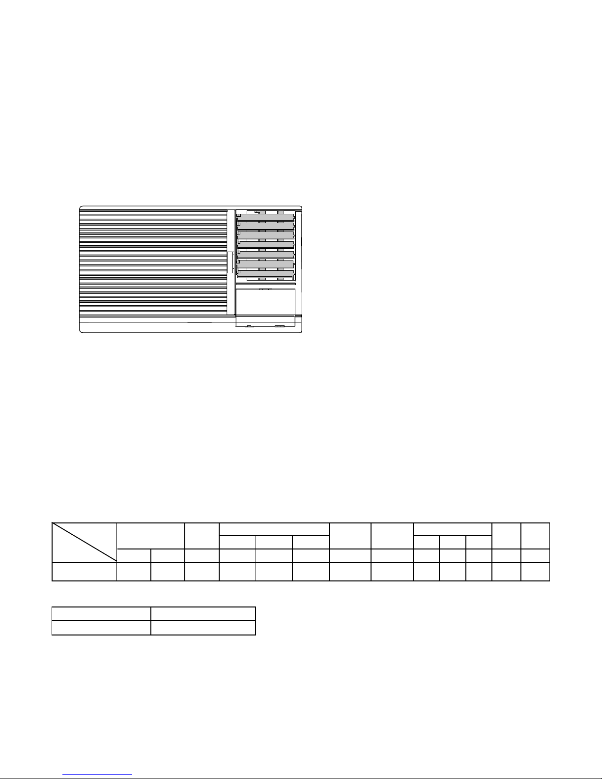
Product Component Identification
Vertical Airflow Direction Vane
(Airflow direction adjusment up-anddown).
Control Panel
Cabinet and Control Panel
- 2 -
Air Intake
Grille
Air Filter
Air Outlet
Grille
Horizontal Airflow Direction Vane
(Airflow direction adjusment side to
side).
Grille Door

1.
2.
3.
4.
5.
Operating Instructions
Maximum
Temperature
Minimum
Temperature
DBT : Dry Bulb Temperature.
WBT : Wet Bulb Temperature.
WBT
26
15
DBT
43
21
Outdoor
WBT
23
15
Indoor
DBT
32
21
- 3 -
Power Suplly
Set the main control switch to the OFF position,
and confirm that the power supply cord is
connected to a proper AC outlet.
Set either LOW COOL or
HIGH COOL, as required. (
Fan setting operates the fan
only ).
Main Control Switch
Caution: If the timer is turned of ,wait at least 3
minutes before restarting the operation ( the
timer set to ON or setting hour).
Thermostat Control Switch
Set the thermostat
control at the desired
setting. (ussually at 6 ~ 7
is recommended setting
position). If the room
temperature is not
satisfactory after a
reasonable amount of
time, turn the control
clockwise to cool the
room more, or anti
clockwise to cool the
room less.
When the termostat control is set to 10, moisture may
freeze onto the coils and prevent effective cooling. If
this happens, turn the main control switch to FAN,
and the thermostat control switch anti clockwise. This
will quickly defrost the cooling coil and resume
normal cooling.
Vertical Airflow Direction Vane
(Airflow direction adjusment Up-and-Down)
The vertical airflow
direction vane may
be positioned using
tabs to deflect the air
upward, downward,
or straight on.
Vertical Airflow Direction Vane
Horizontal Airflow Direction Vane
(Airflow direction adjusment Side-to-Side)
The horizontal
airflow direction
vane may be
adjusted by lever to
deflect the air side to
side ( left,right, or
straight).
Recommendation
Use the air conditioner under the following conditions as below:
Operating temperature range.
(Unit in oC)
Humidity does not exceed 90 %.
Continuous operation at over 90 % humidity
may create condensation and waterdrops on
the intake and outlet vents.
 Loading...