

Panasonic CW-C241SE Service Manual
CONTENTS
• PRODUCT SPECIFICATIONS ................................................................................................1
• DIMENSIONS ..........................................................................................................................2
• WIRING DIAGRAM..................................................................................................................2
• REFRIGERATION CYCLE DIAGRAM.....................................................................................3
• AIR CONDITIONER PERFORMANCE EVALUATION............................................................3
• HOW TO INSTALL.............................................................................................................4 ~ 5
• HOW TO OPERATE................................................................................................................6
• TROUBLESHOOTING GUIDE ................................................................................................ 7
• CARE AND MAINTENANCE ...................................................................................................8
• EXPLODED VIEW ...................................................................................................................9
• REPLACEMENT PARTS LIST .............................................................................................. 10
ORDER NO. MAC9607030C3
© 1996 Matsushita Industrial Corp. Sdn. Bhd.
(11969 - T)
All rights reserved. Unauthorized copying and
distribution is a violation of law.
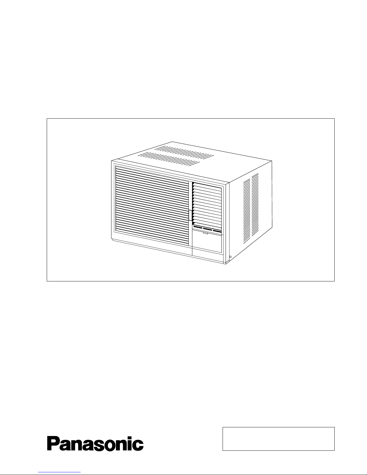
MODEL : CW-C241SE
Service Manual
Room Air Conditioner
Panasonic
– 1 –
CW-C241SE
WARNING
This service information is designed for experienced repair technicians only and is not designed for use by the general
public. It does not contain warnings or cautions to advise non-technical individuals of potential dangers in attempting
to service a product. Products powered by electricity should be serviced or repaired only by experienced professional technicians.
Any attempt to service or repair the product or products dealt with in this service information by anyone else could result in serious injury
or death.
Precaution of Low Temperature
In order to avoid frostbite, be assured of no refrigerant leakage during the installation or repairing of refrigeration circuit.
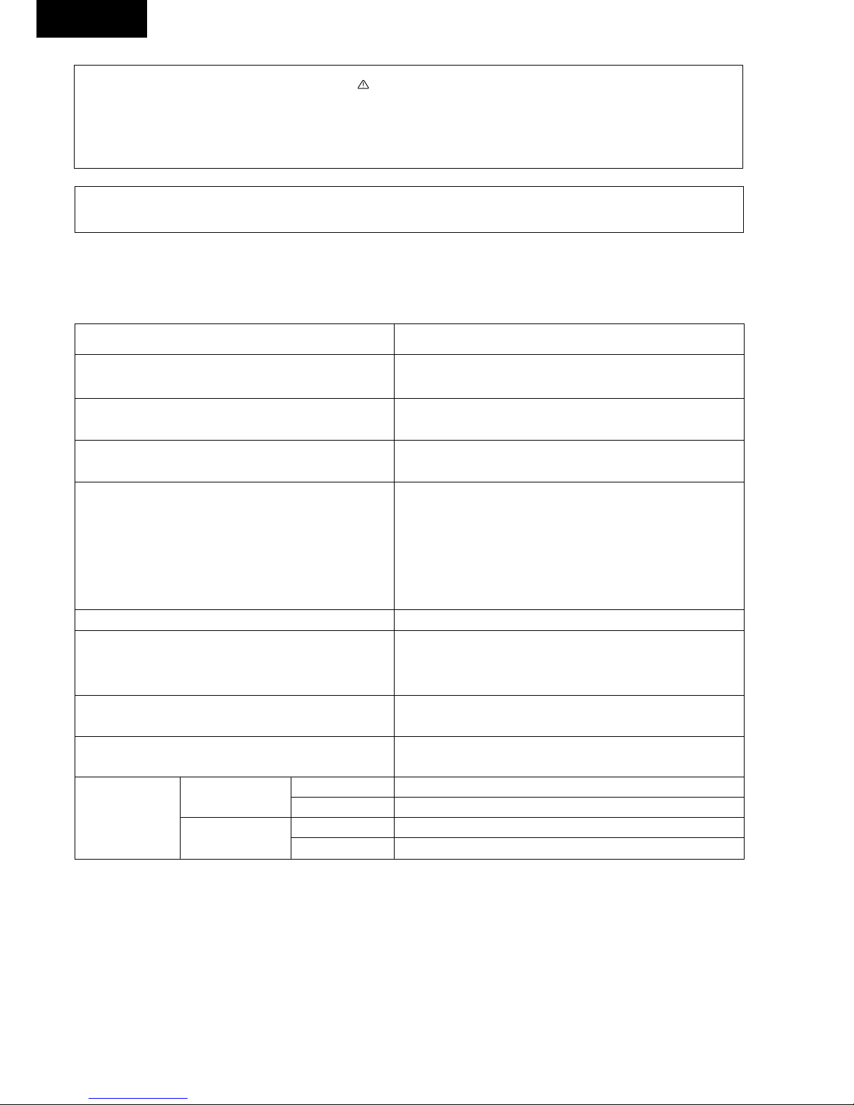
PRODUCT SPECIFICATIONS
MODEL
CAPACITY (Btu/h) 22,510–22,510
(W) 6,600–6,600
MOISTURE REMOVAL (s/h) 4.0
(Pints/h) 8.5
AIR CIRCULATION (m3/min) 17.0
(Cft/min) 600
ELECTRICAL DATA Phase Ø Single
Cycle (Hz) 50
Voltage (V) 230–220V
Running Current (A) 14.5–14.4
Starting Current (A) 60
Input (W) 3,000–2,950
COMPRESSOR OUTPUT (W) 2,200
CABINET Height (mm) 16–7/8" (428)
DIMENSIONS Width (mm) 26" (660)
Depth (mm) 28–3/4" (730)
NET WEIGHT (kg) 72
(lbs) 160
REFRIGERANT (R–22) (g) 1,350
(oz) 47.7
58–57
CW-C241SE
NOISE LEVEL
High
Low
Indoor (dB)
Outdoor (dB)
Indoor (dB)
Outdoor (dB)
* Specifications are subject to change without notice for further improvement.
67–66
54–53
64–63
CW-C241SE
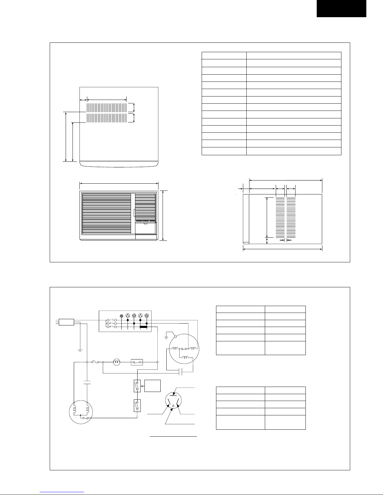
DIMENSIONS
– 2 –
ITEM CW-C241SE
A Width 26" (660)
B Height 16 – 7/8" (428)
C Depth 28 – 3/4" (730)
D 26 – 25/32" (680)
E 1 – 31/32" (50)
F 11 – 13/16" (300)
G 2 – 3/64" (75)
I 3/64" (15)
J 10 – 13/16" (288)
K 15 – 11/32" (389.6)
L 12 – 17/32" (318)
M 3 – 5/32" (80)
N 3 – 35/64" (90)
Unit : (mm)
K
N
N
J
B
A
FRONT VIEW
TOP VIEW
M
L
Panasonic
E
F
G
2-3/32"
(53)
13-25/32"
(350)
C
I
SIDE VIEW
D
G
WIRING DIAGRAM
ORANGE
YELLOW
Resistance of Fan Motor windings and rated Capacitor
Resistance of Compressor windings and rated Capacitor
POWER SUPPLY CORD
1Ø, 230-220V, 50Hz
COMPRESSOR
1
2
1
2
4
0
MAIN SWITCH
AIR SWING
SELECT SWITCH
AIR SWING
MOTOR
YELLOW/GREEN
3
BROWN
YELLOW/GREEN
BLUE
FUSE (5A)
1 P
BLUE
BLUE
BLACK
WHITE
WHITE
BLACK
BLUE BLUE
WHITE
RED
BLUE
CAPACITOR
RED
BLUE
R S
C
YELLOW
CAPACITOR
THERMOSTAT
(LOW TEMP.)
THERMOSTAT
(TEP. CONTROL)
FOR MODEL
CW-C241SE
ONLY
COMP. TERMINAL
YELLOW (C)
BLUE (R)
RED (S)
TRADE MARK
BROWN
FAN MOTOR
CW-C241SE
Connection 2JS438D4AA02
C-R 0.95
C-S 4.39
CAPACITOR
CWA31539
45µF/370VAC
CW-C241SE
Connection CWA92125
BLUE–YELLOW 18.8
YELLOW–ORANGE 6.25
RED–YELLOW 51.5
CAPACITOR
CWA31244
3µF/400VAC
* Resistance at 20°C of Ambient Temp.
CW-C241SE
– 3 –
* Indoor temp. at 27°C (DB), 19°C (WB) and
Outdoor at 35°C , 24°C.
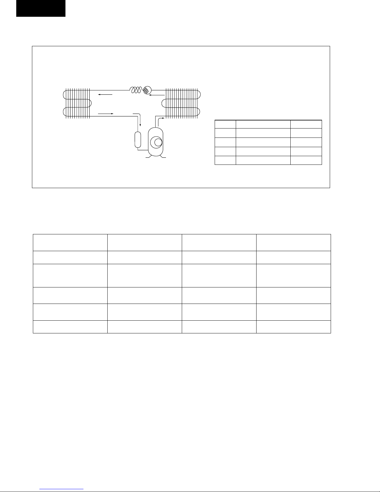
REFRIGERATION CYCLE DIAGRAM
2
6
1
BC
A
4
3
5
D
ITEM PRESSURE (kg/cm2) TEMP. (°C)
A 17.5 ~ 21.0 75 ~ 90
B 17.2 ~ 20.7 38 ~ 45
C 5.5 ~ 6.1 7 ~ 15
D 5.3 ~ 5.8 5 ~ 15
1 Compressor
2 Condenser
3 Strainer
4 Capillary Tube
5 Evaporator
6 Accumulator
AIR CONDITIONER PERFORMANCE EVALUATION
SUCTION & DISCHARGE AIR
CURRENT DETERMINATION REMEDY
TEMPERATURE DIFFERENCE
8°C and over as specified nothing wrong • none
8°C and over higher than specified nothing wrong, outdoor • improve heat radiation
temperature is too high, heat
radiation is not efficient.
under 8°C higher than specified something is preventing heat • excessive amount of refrigerant
radiation • improve heat radiation
under 8°C lower than specified leakage of refrigerant or • locate repair leak
refrigerant system is blocked • flush refrigeration cycle
under 8°C higher than specified by 50% compressor defect • replace the compressor
* Note: Room air humidity is relatively higher, the Temp. difference will be smaller.
 Loading...