

Panasonic CW-C180ES, CW-C240ES, CW-A180ES, CW-A240ES, CW-SC180ES Service Manual

1 Product Specifications 2
2 Dimensions
3
3 Wiring Diagram
4
4 Refrigeration Cycle Diagram
6
5 Air Conditioner Performance Evaluation
7
6 Troubleshooting Guide
7
7 Operating Instructions
9
© 2000 Matsushita Industrial Corp. Sdn. Bhd.
(11969-T). All rights reserved. Unauthorized copying
and distribution is a violation of law.
CW-C180ES
CW-C240ES
CW-A180ES
CW-A240ES
CW-SC180ES
8 How to Install 13
9 Technical Data
17
10 Care and Maintenance
19
11 Service Information
20
12 Exploded View
21
13 Replacemen t Part List
22
Room Air Conditioner
CONTENTS
Page Page
Order No. MAC0011061C3
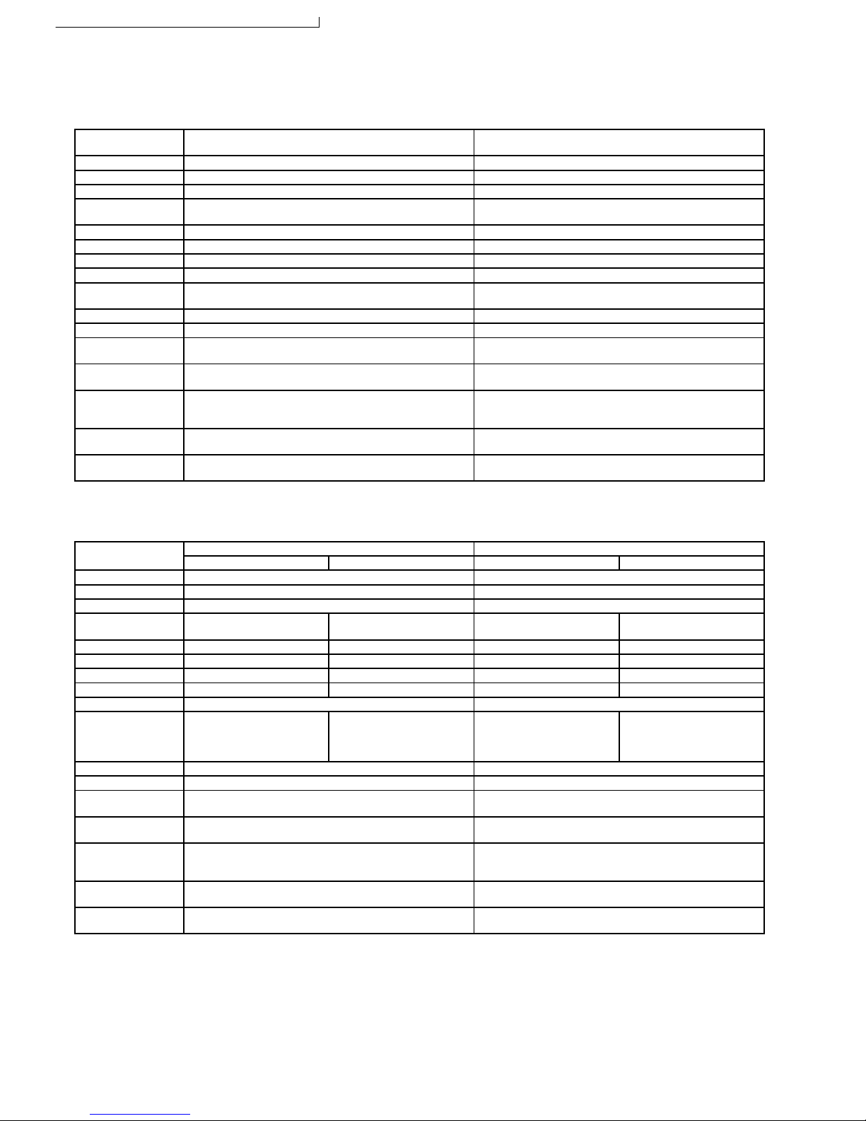
1 Product Specifications
1.1. CW-C180ES, CW-C240ES & CW-SC180ES.
Model CW-C180ES
CW-SC180ES
CW-C240ES
Phase Single Single
Voltage 220 V 220 V
Frequency 60 Hz 60 Hz
Capacity 5.42 kW
18,500 Btu/h
7.03 kW
24,000 Btu/h
Running Current 9.7 A 12.8 A
Input Power 2.09 kW 2.72 kW
EER 8.85 Btu/h.W 8.82 Btu/h.W
Starting Current 39 A 51 A
Noise Level Indoor (High / Low): 52 / 48 dB(A)
Outdoor (High / Low): 59 / 55 dB(A)
Indoor (High / Low): 58 / 54 dB(A)
Outdoor (High / Low): 63 / 60 dB(A)
Fan Motor Output 100 W 170 W
Compressor Output 1.4 kW 1.7 kW
Moisture Removal 0.7 Ltr/h
1.5 Pint/h
1.3 Ltr/h
2.7 Pint/h
Air Circulation 14.0 m3/min.
490 Ft
3
/min.
16.8 m3/min.
590 Ft
3
/min.
Dimensions Height: 16-7/8 inches (428 mm)
Width: 26 inches (660 mm)
Depth: 27-9/16 inches (700 mm)
Height: 16-7/8 inches (428 mm)
Width: 26 inches (660 mm)
Depth: 30-11/32 inches (770 mm)
Net Weight 62 kg
137 Ib
70 kg
154 Ib
Refrigerant (R-22) 760 g
26.8 oz
1.08 kg
38.1 oz
Note: Specifications are subject to change without notice for further improvement.
1.2. CW-A180ES & CW-A240ES.
Model CW-A180ES CW-A240ES
Cooling Heating Cooling Heating
Phase Single Single
Voltage 220 V 220 V
Frequency 60 Hz 60 Hz
Capacity 5.13 kW
17,500 Btu/h
4.60 kW
15,700 Btu/h
6.45 kW
22,000 Btu/h
5.60 kW
19,100 Btu/h
Running Current 10.1 A 8.0 A 13.3 A 10.5 A
Input Power 2.17 kW 1.70 kW 2.82 kW 2.23 kW
EER 8.06 Btu/h.W ------ 7.80 Btu/h.W -----COP ------ 9.24 Btu/h.W ------ 8.57 Btu/h.W
Starting Current 39 A 51 A
Noise Level Indoor (High / Low):
52 / 48 dB(A)
Outdoor (High / Low):
59 / 55 dB(A)
Indoor (High / Low):
52 / 48 dB(A)
Outdoor (High / Low):
60 / 56 dB(A)
Indoor (High / Low):
58 / 54 dB(A)
Outdoor (High / Low):
64 / 61 dB(A)
Indoor (High / Low):
58 / 54 dB(A)
Outdoor (High / Low):
65 / 62 dB(A)
Fan Motor Output 100 W 170 W
Compressor Output 1.4 kW 1.7 kW
Moisture Removal 0.6 Ltr/h
1.3 Pint/h
1.1 Ltr/h
2.3 Pint/h
Air Circulation 14.0 m3/min.
490 Ft
3
/min.
16.8 m3/min.
590 Ft
3
/min.
Dimensions Height: 16-7/8 inches (428 mm)
Width: 26 inches (660 mm)
Depth: 27-9/16 inches (700 mm)
Height: 16-7/8 inches (428 mm)
Width: 26 inches (660 mm)
Depth: 30-11/32 inches (770 mm)
Net Weight 62 kg
137 Ib
70 kg
154 Ib
Refrigerant (R-22) 830 g
29.3 oz
1.12 kg
39.5 oz
Note: Specifications are subject to change without notice for further improvement.
2
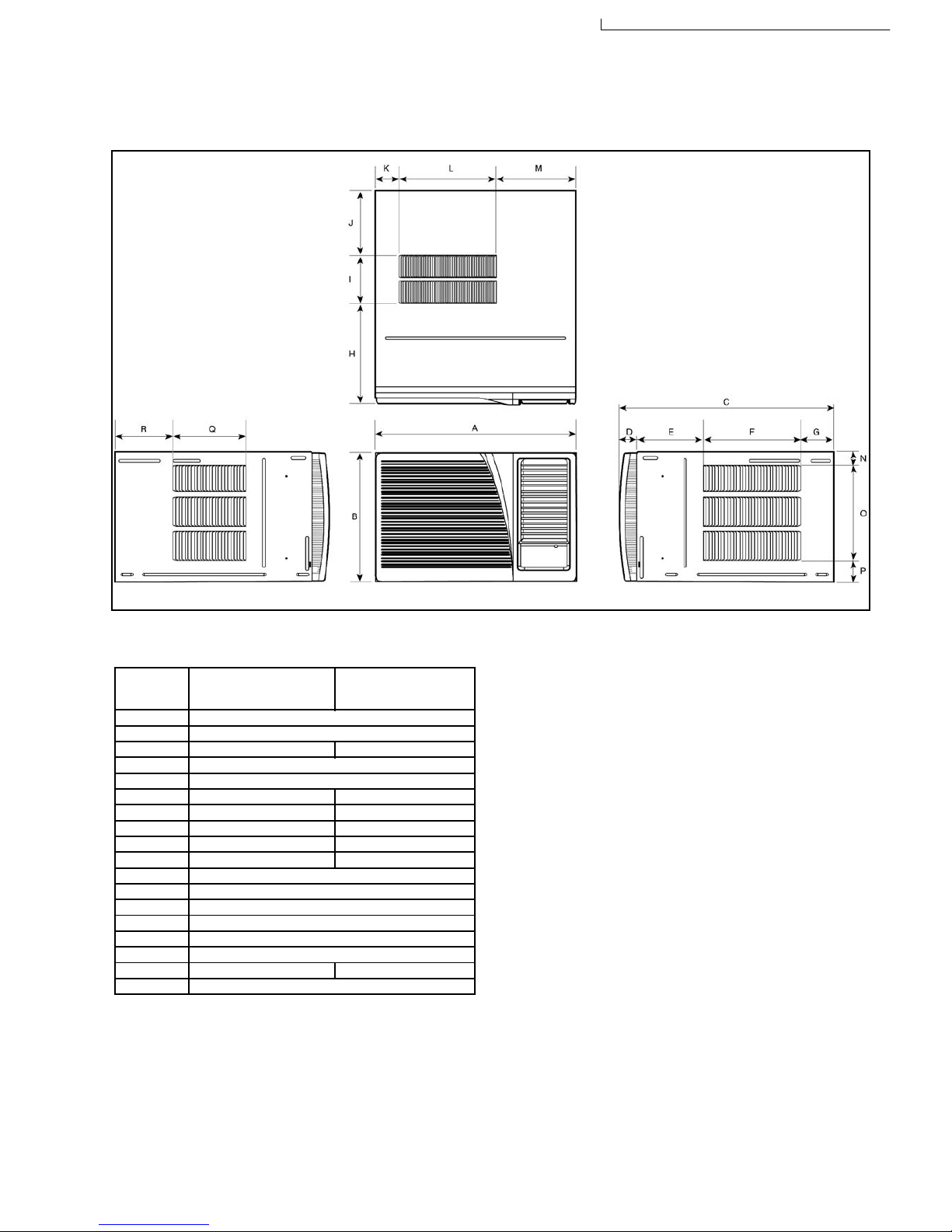
2 Dimensions
Item CW-C180ES
CW-A180ES
CW-SC180ES
CW-C240ES
CW-A240ES
A - Width 26” (660)
B - Height 16-7/8” (428)
C - Depth 27-9/16” (700) 30-11/32” (770)
D 1-31/32” (50)
E 8-21/32” (220)
F 12-19/32” (320) 10-1/4” (260)
G 4-11/32” (110) 9-7/16” (240)
H 13-5/32” (334) 12-3/4” (324)
I 5-3/16” (132) 7-9/16” (192)
J 9-7/32” (234) 10” (254)
K 3-5/32” (80)
L 12-17/32” (318)
M 10-5/16” (262)
N 1-21/32” (42)
O 12-17/32” (318)
P 2-11/16” (68)
Q 9-7/16” (240) 12-7/32” (310)
R 7-15/32” (190)
Unit: Inch (mm)
2.1. Top View, Front View & Side View.
2.2. Unit.
3
CW-C180ES / CW-C240ES / CW-A180ES / CW-A240ES / CW-SC180ES
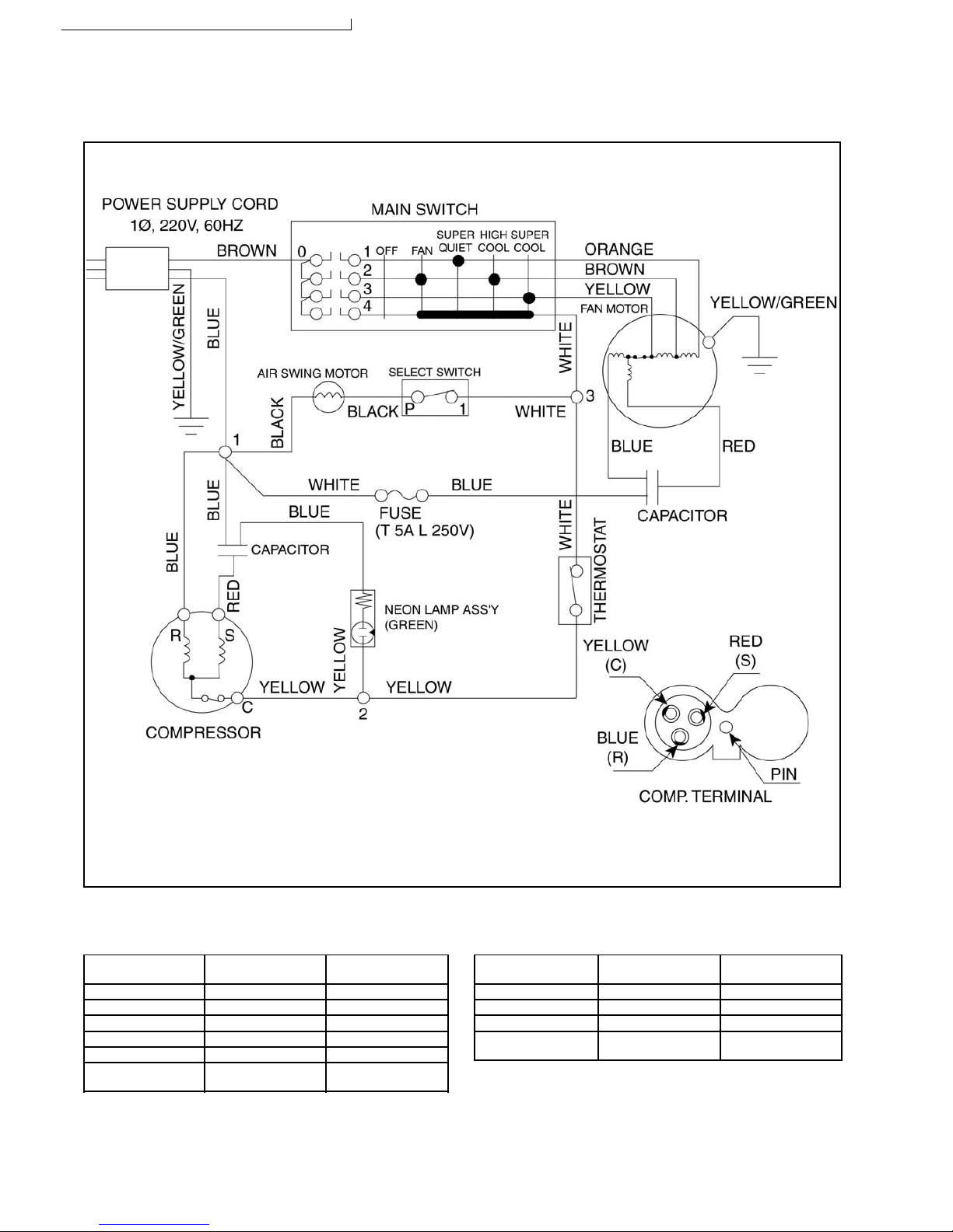
3 Wiring Diagram
3.1.1. Resistance of Fan Motor windings
and the rated Capacitor.
CW-C180ES
CW-SC180ES
CW-C240ES
Connection CWA951053 CWA951069
Blue - Yellow 34.1 Ω 22.25 Ω
Yellow - Brown 6.5 Ω 4.04 Ω
Brown - Orange 6.2 Ω 2.97 Ω
Red - Yellow 41.1 Ω 27.13 Ω
Capacitor CWA312048
(5µF, 440VAC)
CWA312052
(8µF, 440VAC)
3.1.2. Resistance of Compressor
windings and the rated Capacitor.
CW-C180ES
CW-SC180ES
CW-C240ES
Connection 2KS282H6CA02 2JS350H4CA02
C-R 1.239 Ω 0.934 Ω
C-S 1.721 Ω 1.558 Ω
Capacitor CWA31507
(50µF, 370VAC)
CWA31507
(50µF, 370VAC)
Note: Resistance at 20°C of Ambient Temperature.
3.1. CW-C180ES, CW-C240ES & CW-SC180ES.
4

3.2.1. Resistance of Fan Motor windings
and the rated Capacitor.
CW-A180ES CW-A240ES
Connection CWA951059 CWA951073
Blue - Yellow 34.1 Ω 22.25 Ω
Yellow - Orange 12.7 Ω 7.01 Ω
Red - Yellow 41.1 Ω 27.13 Ω
Capacitor CWA312048
(5µF, 440VAC)
CWA312052
(8µF, 440VAC)
3.2.2. Resistance of Compressor
windings and the rated Capacitor.
CW-A180ES CW-A240ES
Connection 2KS282H6CA02 2JS350H4CA02
C-R 1.239 Ω 0.934 Ω
C-S 1.721 Ω 1.558 Ω
Capacitor CWA31507
(50µF, 370VAC)
CWA31507
(50µF, 370VAC)
Note: Resistance at 20°C of Ambient Temperature.
3.2. CW-A180ES & CW-A240ES.
5
CW-C180ES / CW-C240ES / CW-A180ES / CW-A240ES / CW-SC180ES
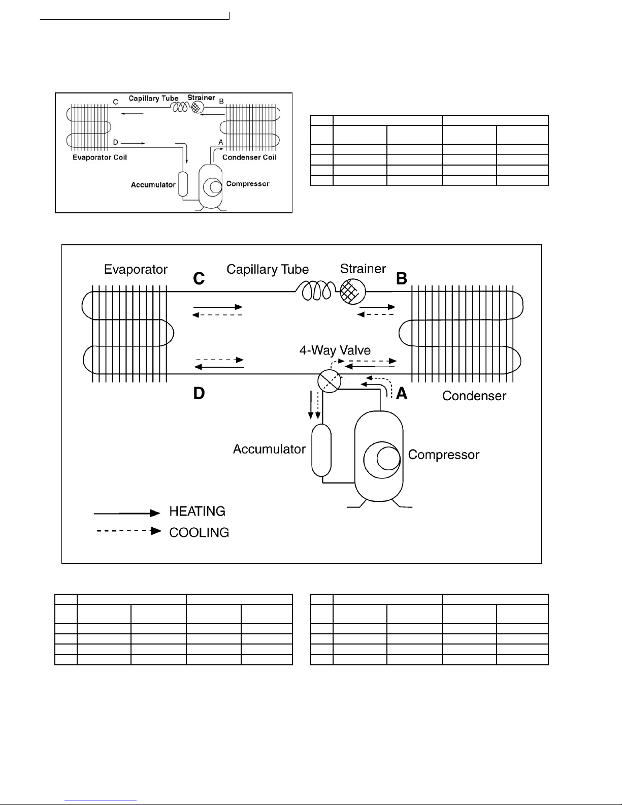
4.2.1. Cooling.
CW-A180ES CW-A240ES
Item Pressure
(MPa)
Temperature
(°C)
Pressure
(MPa)
Temperature
(°C)
A 2.83 ~ 2.93 76 ~ 92 2.79 ~ 2.89 84 ~ 100
B 2.73 ~ 2.83 55 ~ 65 2.69 ~ 2.79 56 ~ 66
C 0.64 ~ 0.70 12 ~ 16 0.58 ~ 0.67 10 ~ 14
D 0.59 ~ 0.65 8~16 0.50 ~ 0.56 8~16
Note: Indoor temperature at 27°C (DB), 19°C (WB) and Outdoor at
35°C (DB), 24°C (WB) for Cooling.
4.1.1. Cooling.
CW-C180ES & CW-SC180ES CW-C240ES
Item Pressure
(MPa)
Temperature
(°C)
Pressure
(MPa)
Temperature
(°C)
A 2.65 ~ 2.85 81 ~ 91 2.77 ~ 2.97 78 ~ 88
B 2.55 ~ 2.75 54 ~ 64 2.67 ~ 2.87 53 ~ 63
C 0.63 ~ 0.69 10 ~ 15 0.57 ~ 0.62 9~14
D 0.58 ~ 0.64 9~14 0.55 ~ 0.60 8~13
Note: Indoor temperature at 29°C (DB), 19°C (WB) and Outdoor at
46°C (DB), 24°C (WB) for Cooling.
4.2.2. Heating.
CW-A180ES CW-A240ES
Item Pressure
(MPa)
Temperature
(°C)
Pressure
(MPa)
Temperature
(°C)
A 0.26 ~ 0.32 -9 ~ -1 0.26 ~ 0.32 -10 ~ -3
B 0.40 ~ 0.47 0~4 0.42 ~ 0.49 1.5 ~ 5.5
C 1.34 ~ 1.44 32 ~ 42 1.52 ~ 1.62 42 ~ 48
D 1.49 ~ 1.59 41 ~ 57 1.62 ~ 1.72 50 ~ 60
Note: Indoor temperature at 20°C (DB), 15.5°C (WB) and Outdoor at
7°C (DB), 6°C (WB) for Heating.
4 Refrigeration Cycle Diagram
4.1. CW-C180ES, CW-C240ES & CW-SC180ES.
4.2. CW-A180ES & CW-A240ES.
6
5 Air Conditioner Performance Evaluation
5.1. Cooling.
Intake & Discharge Air
Temperature Difference
Current Drain Determination Remedy
• 8°C and over (14.4°F) • As specified. • Nothing wrong. • None.
• 8°C and over (14.4°F) • Higher than specified. • Nothing wrong, outdoor
temperature is too high, heat
radiation is not efficient.
• Improve heat radiation.
• Under 8°C (14.4°F) • Higher than specified. • Something is preventing heat
radiation.
• Excessive amount of refrigerant.
• Improve heat radiation.
• Under 8°C (14.4°F) • Lower than specified. • Leakage of refrigerant or
refrigerant system is blocked.
• Locate and repair leak.
• Flush refrigeration cycle.
• Under 8°C (14.4°F) • Higher than specified by
50%.
• Compressor defect or
compressor capacitor defect.
• Replace the compressor or
compressor capacitor.
Note: Room air humidity is relatively higher, the temperature difference will be smaller.
5.2. Heating.
Intake & Discharge Air
Temperature Difference
Current Drain Determination Remedy
• 14°C and over (25.2°F) • As specified. • Nothing wrong. • None.
• 14°C and over (25.2°F) • Higher than specified. • Nothing wrong, outdoor
temperature is high.
• Something is preventing heat
radiation at indoor heat
exchanger.
• None.
• Clean air filter.
• Under 14°C (25.2°F) • Lower than specified. • Nothing wrong, outdoor
temperature is low.
• Something is preventing heat
radiation at outdoor heat
exchanger.
• Leakage of refrigerant.
• Refrigerant system is blocked.
• None.
• Improve heat radiation at
outdoor heat exchanger.
• Locate and repair leak.
• Flush refrigeration cycle.
• Under 14°C (25.2°F) • Higher than specified by
50%.
• Compressor defect.
• Compressor capacitor defect
• Replace the compressor.
• Replace the compressor
capacitor.
Note: Room air humidity is relatively higher, the temperature difference will be smaller.
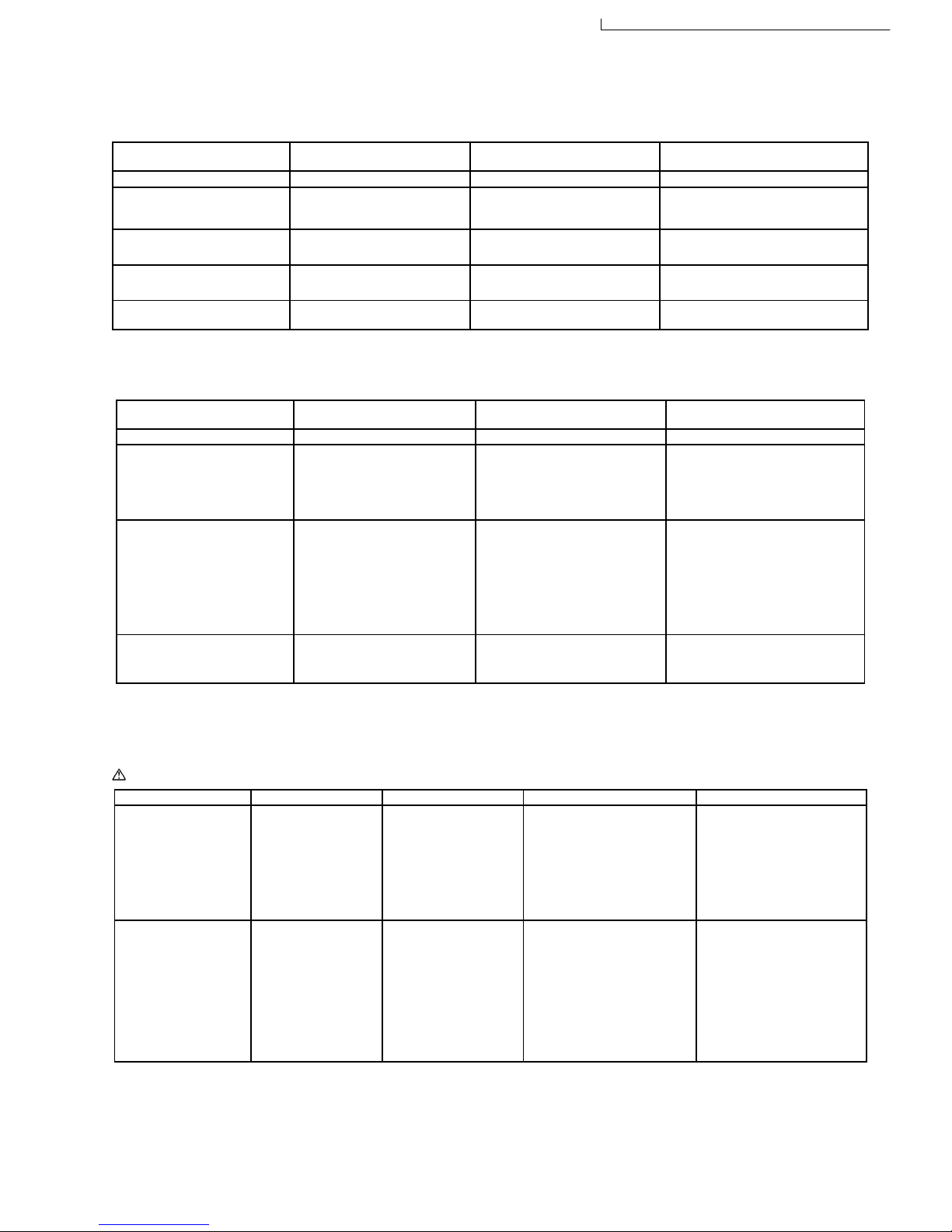
6 Troubleshooting Guide
Warning: Disconnect unit from electrical power supply before making any electrical checks.
Trouble Check Result Cause Remedy
Fan Motor and
Compressor won’t run.
• Supply Voltage
• Fuse Box or Circuit
Breaker.
• Power cord or
Wiring Harness.
• Thermostat Setting.
• Less than 10% by
Rated.
• Open Contacts.
• Pulled loose or
Shorted.
• Higher than room
temp.
• Temporary or Permanent?
• Customer Restarted unit
immediately without waiting
3 minutes.
• Consult ELECTRICIAN, If
permanent.
• Repair Open Circuit.
• WAIT FOR 3 MINUTES.
• Repair or Replace it.
• Set it LOWER.
Fan Motor won’t run
(Compressor run).
• Objects around
Fan.
• RESISTANCE
between Wires.
• Capacitor Fan
Motor.
• Main Control
Switch.
• Locked Fan.
• Shorted / Open
circuit.
• OHM Meter doesn’t
Deflect.
• No contacts at
Position Shown.
• Fan Hitting Cowling or
• Foreign Materials.
• Frozen Bearings.
• Shorted or Burned out.
• Capacitor Defect.
• Main Control Switch defect.
• Adjust Fan position setting
screw.
• Remove Foreign Materials.
• Replace Fan Motor.
• Replace Fan Motor.
• Replace Capacitor Fan.
• Replace Main Control
Switch.
7
CW-C180ES / CW-C240ES / CW-A180ES / CW-A240ES / CW-SC180ES
 Loading...