

Panasonic CU-PC9CKV, CU-PC12CKV, CS-PC12CKV, CS-PC9CKV Service Manual
Order No: GMAC0401004C3
Room Air Conditioners
CS-PC9CKV CU-PC9CKV
CS-PC12CKV CU-PC12CKV
CONTENTS
Page Page
1 Functions 2
2 Product Specifications
3 Dimensions
4 Refrigeration Cycle Diagram
5 Block Diagram
6 Wiring Diagram
7 Operation Details
8 Installation
9 2-way, 3-way Valve
10 Disassembly of the parts
11 Trouble-shooting guide 47
5
12 Technical Data
13 Exploded View
9
12
14 Replacement Parts List
15 Exploded View
13
14
16 Replacement Parts List
17 Exploded View
15
22
18 Replacement Parts List
36
19 ELECTRONIC CIRCUIT DIAGRAM
43
© Guangzhou Matsushita Air Conditioner Co., Ltd.
(GMAC) All rights reserved. Unauthorized copying
and distribution is a violation of law.
49
51
52
53
54
55
56
57
CS-PC9CKV CU-PC9CKV / CS-PC12CKV CU-PC12C KV
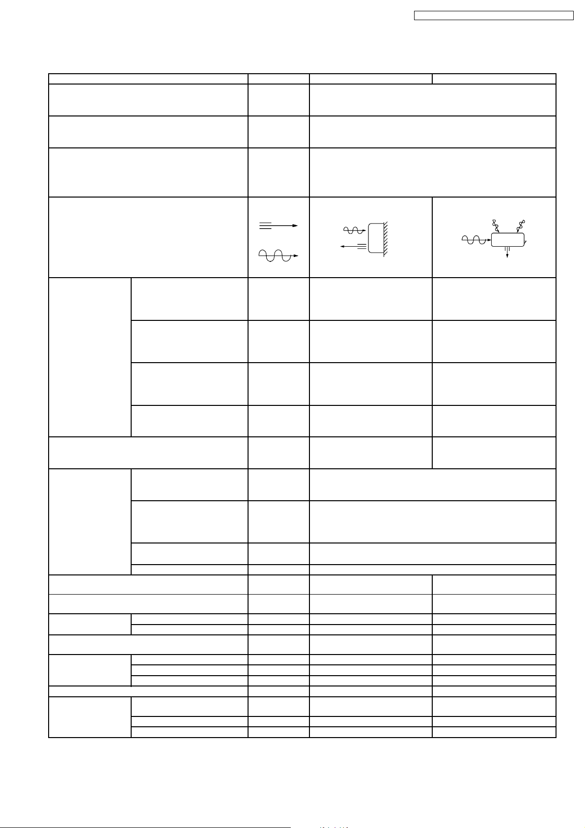
1 Functions
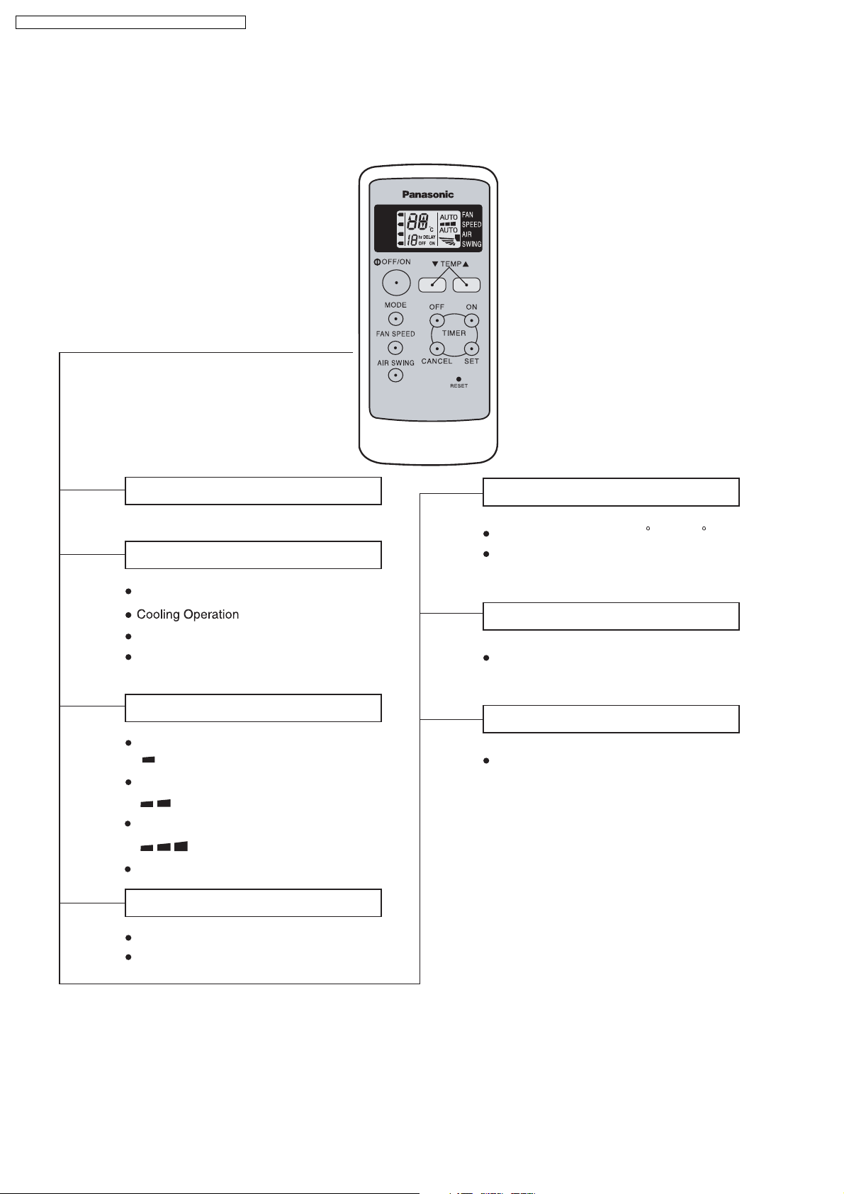
Operation START/ST OP
Operation Mode Selection
Automatic Operation
Soft Dry Mode Operation
Air Circulation Operation
Mode
AUTO
COOL
DRY
FAN
S
T
D
Room Temperature Setting
Temperature Setting(16 C to 30 C)
Auto Operation
Timer Operation Selection
Stop/Start Operation Control
(set the ON/OFF Timer hourly later)
Indoor Fan Speed Selection
Low Speed
Medium Speed
High Speed
Automatic Speed
Airflow Direction Control
Auto Airflow Direction
Airflow Direction Manual Control
Set /Cancel Timer Operation
Set timer/Cancel the set timer
2
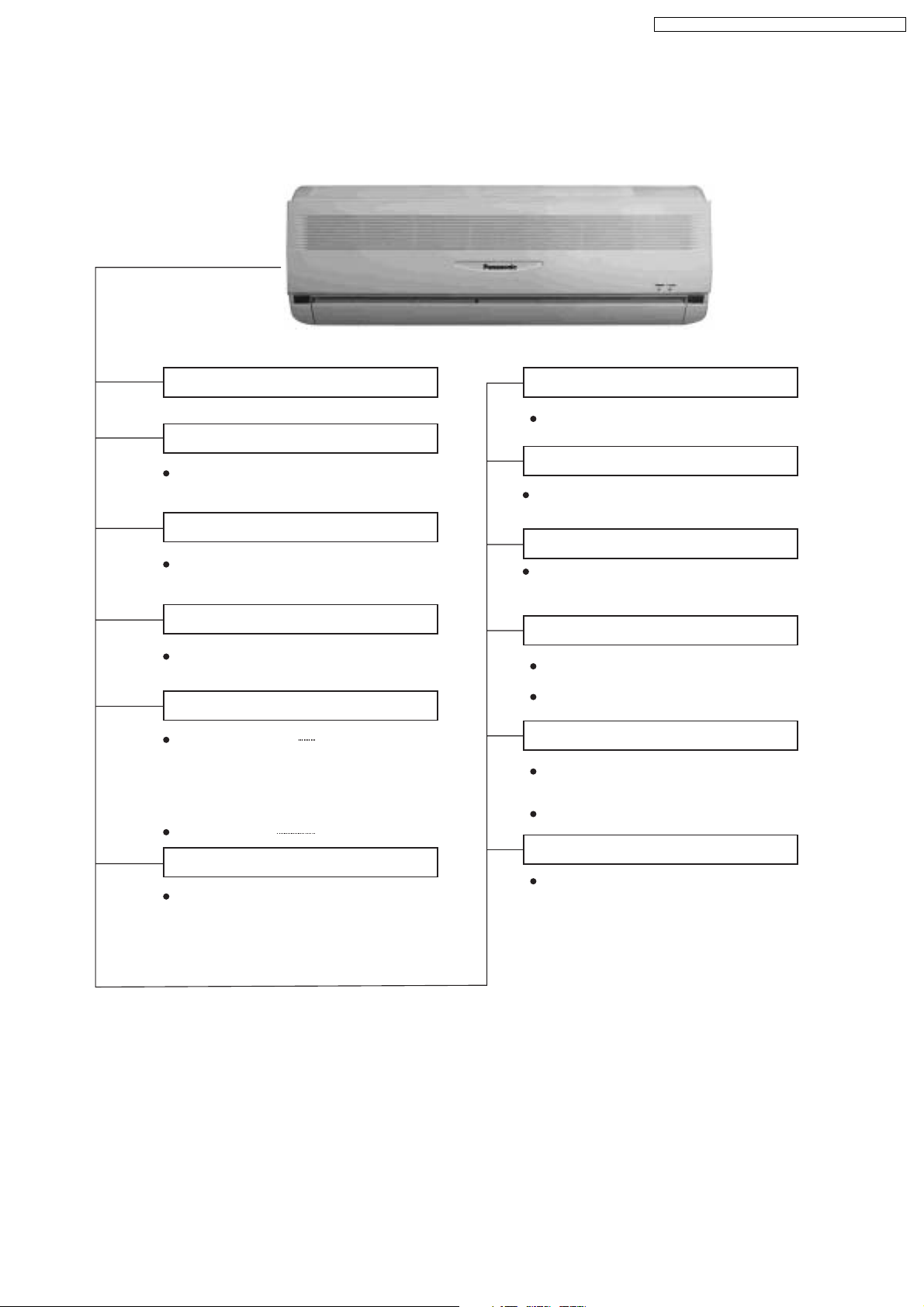
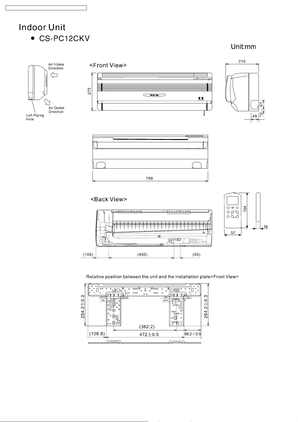
Indoor Unit
CS-PC9CKV CU-PC9CKV / CS-PC12CKV CU-PC12C KV
Power Switch ON/OFF
Auto Mode Operation Selection Button
When the remote control cannot be used,
please use this button.
Signal Receiving Sound Control
Keep pressing this button for 10sec to turn
on or turn off the signal receiving sound.
Test Run
Used when testing or repairing
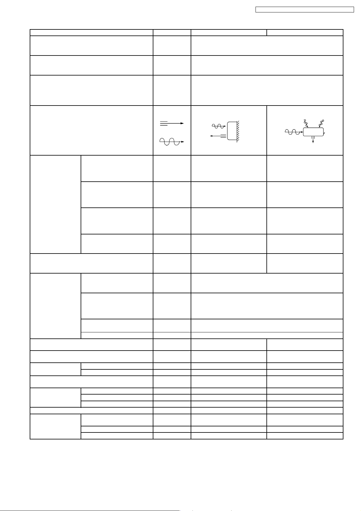
Operation Indication Lamps
Operation (green)
Timer(orange)
Iights up in operation
Blinks during Test
Run operation and
determining Auto
Operation mode
Timer in operation
Operation Mode
Cooling/Soft Dry/Air Circulation/
Auto Operation
Anti-freezing Control for the Evaporator
Cooling or Soft Dry Operation
Time Delay Safety Control
The unit will restart operation after 3-4
minutes after each pause.
Automatic Restarting Control
7-minutes automatic restarting at Cooling
Operation
Indoor Fan Speed Control
High,Med,Low
Auto Fan Speed
Airflow Direction Control
Automatic Airflow Direction Control
The louver automatically swings up and down
Airflow Direction Manual Control
Delayed On-timer Control
For cooling or soft dry mode, the unit
starts 15 minutes before the set time with
the remote control.
3
CS-PC9CKV CU-PC9CKV / CS-PC12CKV CU-PC12C KV
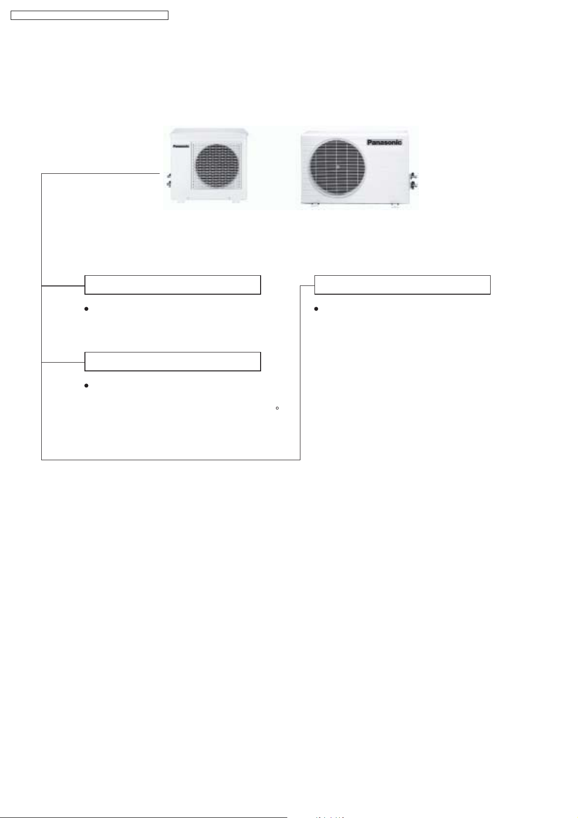
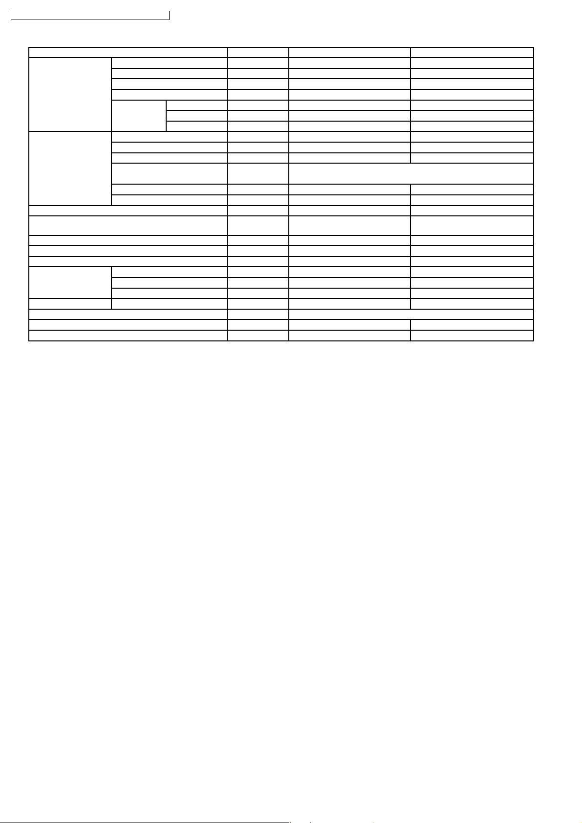
Outdoor Unit
CU-PC9CKV CU-PC12CKV
Anti-reverse Protection
To protect the compressor from reverse
rotation when power off suddenly.
Overload Protector
The 2-step Overload Protector is to protect
the compressor when
1/ temperature of compressor reaches 120 C
2/ high temperature or current enters into the
compressor.
60-seconds Test Operation Control
Once the compressor is activated,it does not
stop for 60 seconds.It stops immediately with
remote controller ON/OFF button.
4
CS-PC9CKV CU-PC9CKV / CS-PC12CKV CU-PC12C KV
2 Product Specifications
Unit CS-PC9CKV CU-PC9CKV
Cooling Capacity kW 2.50
Moisture Removal L/h 1.40
Power Source Phase
Airflow Method OUTLET
Air Circulation Indoor Air (low) m3/min 7.0 —
Indoor Air (medium) m3/min 7.8 —
Indoor Air (high) m3/min 8.8 —
Outdoor Air m3/min — —
V
Cycle
SIDE VIEW TOP VIEW
INTAKE
Single
220-230
60
Noise Level dB(A) High36, Low30 High49
Electrical Data Input W 830-840
Running Current A 4.0-3.9
EER W/W 3.0-2.98
Starting Current A 19
Piping Connection Port
(Flare piping)
Piping Size
(Flare piping)
Drain
Hose
Power Supply Cord Length
(Number of core-wire)
Dimensions Height mm 250 534
Net Weight kg 8.0 26
Compressor Type — Rotary(1 cylinder)
Inner Diameter mm 12 —
Length m 0.6 —
Width mm 770 590
Depth mm 205 255
Motor Type — Induction(2 pole)
Rated Output W — 650
Inch
Inch
Inch
Inch
m 2.2
G: half union 3/8"
L: half union 1/4"
G: gas side 3/8"
L: liquid side 1/4"
3 core-wire/1.5mm
G: 3-way valve 3/8"
L: 2-way valve 1/4"
G: gas side 3/8"
L: liquid side 1/4"
2
—
—
Rolling piston type
5
CS-PC9CKV CU-PC9CKV / CS-PC12CKV CU-PC12C KV
Unit CS-PC9CKV CU-PC9CKV
Air Circulation Type Cross-flow Fan Propeller fan
Motor Type Induction (4 pole) Induction (4 pole)
Input W 38.4 58.2
Rated Output W 13 22
Fan Speed Low rpm 870±60 —
Medium rpm 980±60 —
High rpm 1100±60 880±60
Heat Exchanger Description Evaporator Condenser
Tube Material copper copper
Fin Type slot type Corrugation type
Rows / Stage (Plate fin configuration, forced draft)
2×12 1×20
FPI 18 18
Dimensions mm 610 × 252 × 25.4 568.8 × 508 × 22
Refrigerant Control Device — Capillary Tube
Refrigeration Oil (c.c) — SUNISO 4GDID or ATMOS M60
Refrigerant (R-22) g — 530*
Thermostat Electronic Control —
Protection Device — O.L.P.(25A/230V)
Capillary Length mm — 630
Circulation L/min — 11.7
Inner Diameter mm — 1.5
Air Filter P.P Honeycomb —
Refrigerant Circulation Control Device Capillary
Compressor Capacitor µFV — 30µF, 370V
Fan Motor Capacitor µFV 1.5µF, 400V 1.5µF, 440V
(M56)
•
•
Specifications are subject to change without notice for further improvement.
• •
* 60g for air purging is not included.
6
CS-PC9CKV CU-PC9CKV / CS-PC12CKV CU-PC12C KV
Unit CS-PC12CKV CU-PC12CKV
Cooling Capacity kW 3.50
Moisture Removal L/h 2.1
Power Source Phase
V
Cycle
Airflow Method OUTLET
SIDE VIEW TOP VIEW
Single
220-230
60
INTAKE
Air Circulation Indoor Air (low) m3/min 8.0 —
Indoor Air (medium) m3/min 8.7 —
Indoor Air (high) m3/min 9.9 —
Outdoor Air m3/min — —
Noise Level dB(A) High39, Low33 High47
Electrical Data Input W 1210-1220
Running Current A 5.70-5.50
EER W/W 2.89-2.87
Starting Current A 25
Piping Connection Port
(Flare piping)
Piping Size
(Flare piping)
Drain
Hose
Inner Diameter mm 12 —
Length m 0.6 —
Power Supply Cord Length
(Number of core-wire)
Inch
Inch
Inch
Inch
G: half union 3/8"
L: half union 1/4"
G: gas side 3/8"
L: liquid side 1/4"
m 2.2
3 core-wire/1.5mm
G: 3-way valve 3/8"
L: 2-way valve 1/4"
G: gas side 3/8"
L: liquid side 1/4"
2
—
—
Dimensions Height mm 250 505
Width mm 770 780
Depth mm 205 245
Net Weight kg 8.0 30
Compressor Type — Rotary(1 cylinder)
Rolling piston type
Motor Type — Induction(2 pole)
Rated Output W — 850
7

CS-PC9CKV CU-PC9CKV / CS-PC12CKV CU-PC12C KV
Unit CS-PC12CKV CU-PC12CKV
Air Circulation Type Cross-flow Fan Propeller fan
Motor Type Induction (4 pole) Induction (4 pole)
Input W 43 61
Rated Output W 16 20
Fan Speed Low rpm 980±60 —
Medium rpm 1110±60 —
High rpm 1260±60 740±50
Heat Exchanger Description Evaporator Condenser
Tube Material copper copper
Fin Type slot type Corrugation type
Rows / Stage (Plate fin configuration, forced draft)
2×12 1×19
FPI 21 16
Dimensions mm 610 × 315 × 25.4 706.2 × 482.6 × 22
Refrigerant Control Device — Capillary Tube
Refrigeration Oil (c.c) — SUNISO 4GDID or ATMOS M60
Refrigerant (R-22) g — 800*
Thermostat Electronic Control O.L.P.(25A/230V)
Protection Device — —
Capillary Length mm — 720
Circulation L/min — 11.0
Inner Diameter mm — 1.5
Air Filter P.P Honeycomb —
Refrigerant Circulation Control Device Capillary
Compressor Capacitor µFV — 30µF, 370V
Fan Motor Capacitor µFV 1.5µF, 400V 1.5µF, 400V
(M56)
•
•
Specifications are subject to change without notice for further improvement.
• •
* 60g for air purging is not included.
8

3 Dimensions
CS-PC9CKV CU-PC9CKV / CS-PC12CKV CU-PC12C KV
9
CS-PC9CKV CU-PC9CKV / CS-PC12CKV CU-PC12C KV
10

CS-PC9CKV CU-PC9CKV / CS-PC12CKV CU-PC12C KV
11
CS-PC9CKV CU-PC9CKV / CS-PC12CKV CU-PC12C KV
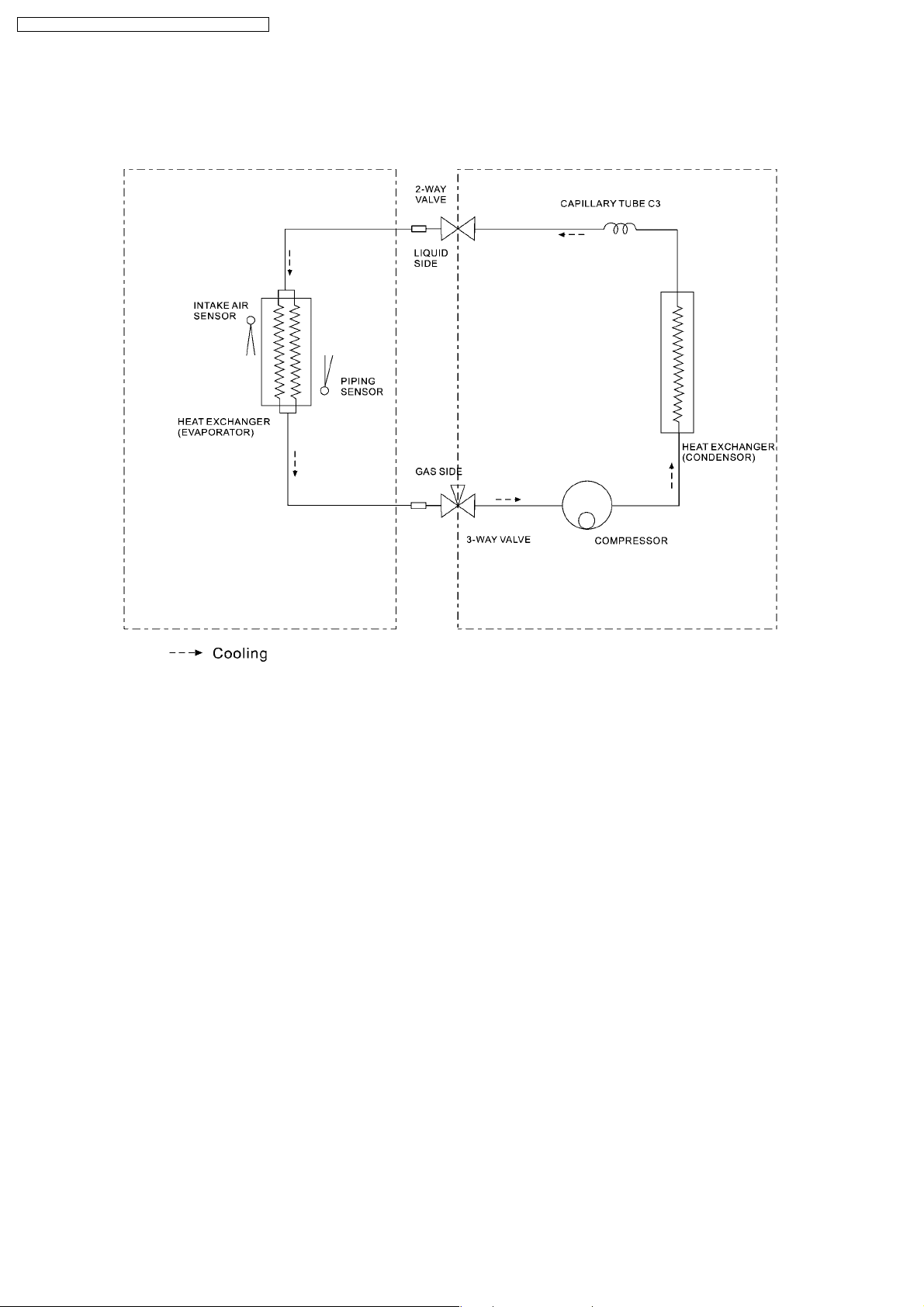
4 Refrigeration Cycle Diagram
4.1. CS/CU-PC9CKV, CS/CU-PC12CKV
12
5 Block Diagram
5.1. CS/CU-PC9CKV,CS/CU-PC12CKV
CS-PC9CKV CU-PC9CKV / CS-PC12CKV CU-PC12C KV
13

CS-PC9CKV CU-PC9CKV / CS-PC12CKV CU-PC12C KV
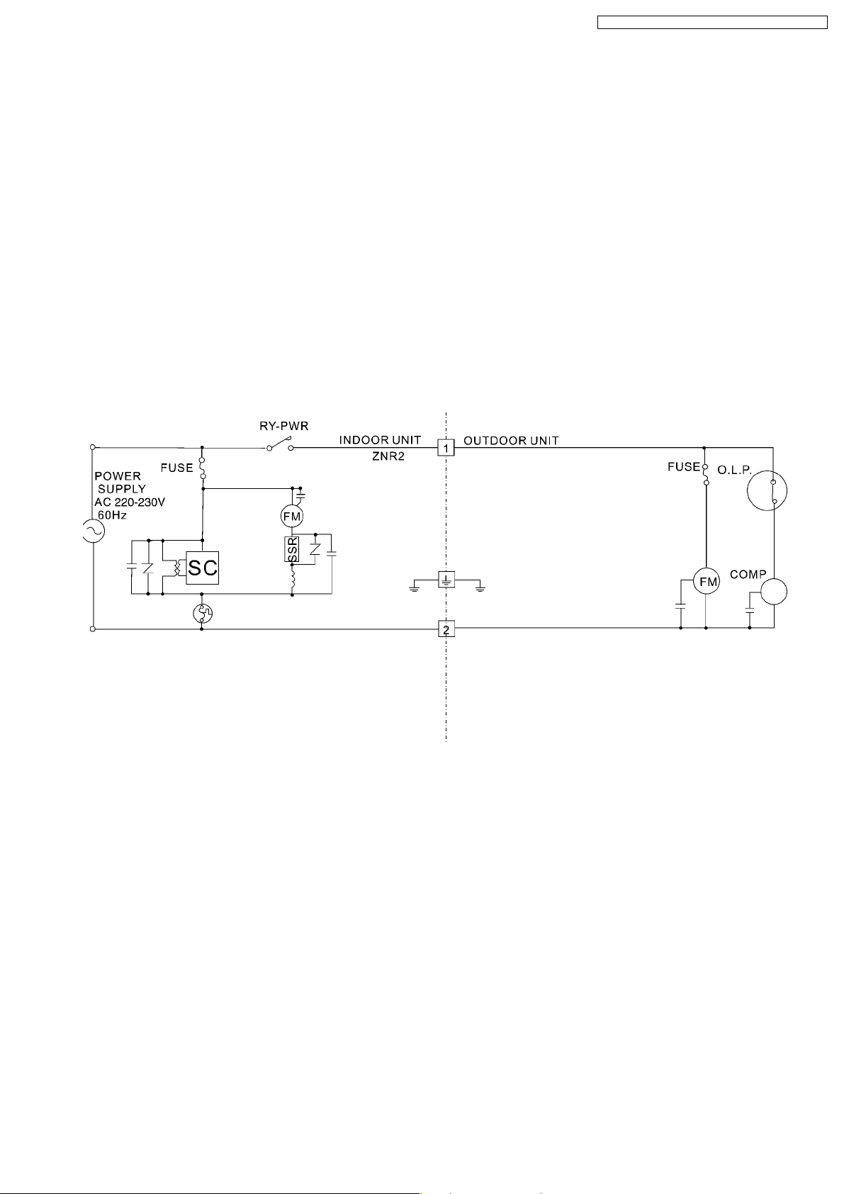
6 Wiring Diagram
6.1. CS/CU-PC9CKV, CS/CU-PC12CKV
14
CS-PC9CKV CU-PC9CKV / CS-PC12CKV CU-PC12C KV
7 Operation Details
7.1. Cooling Mode Operation
•
•
When selecting the Cooling Mode Operation, the unit will operate according to the setting by the Remote Control and the
• •
operation is as the following.
Time Delay Safety Control
•
•
3 min. ---- The compressor is ceased for 3 minutes to balance the pressure in the refrigeration cycle.
• •
•
•
(Protection of compressor).
• •
Automatic Restarting Control
•
•
7 min. ---- The unit will automatically operate in 7 minutes even if the room temperature is not reached.
• •
(Prevention of raising the humidity)
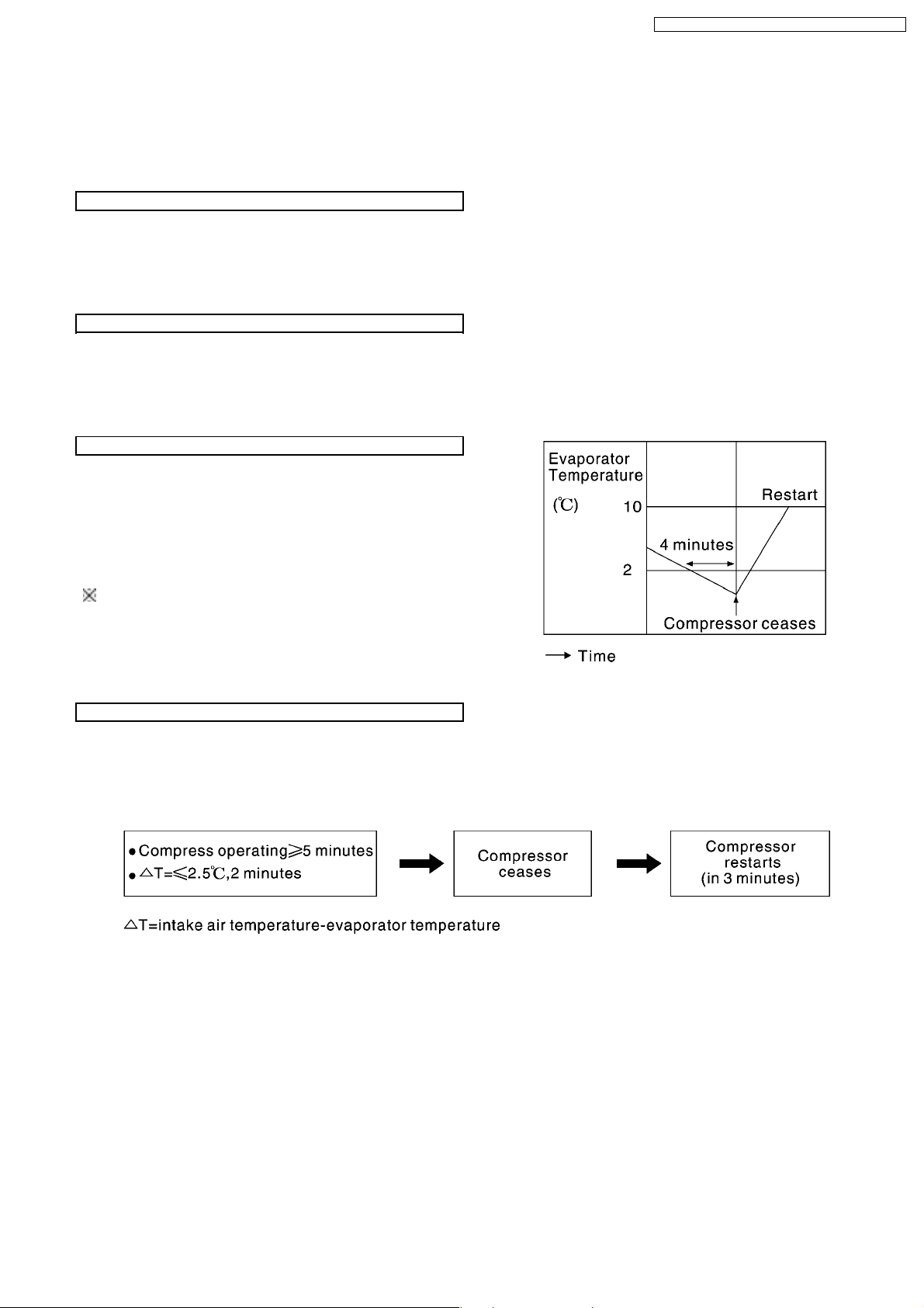
Anti-freezing Control
•
•
If temperature of evaporator is lower than 2°C continuously
• •
for 4 minutes, the compressor will cease to prevent the
evaporator from freezing. Fan speed setting will not be
changed.
•
•
When temperature of evaporator reaches 10°C,
• •
compressor will restart.
During Cooling Mode Operation, the Time Delay Safety Control
is available.
Anti-reversing Control
•
•
If the compressor has been continuously running for 5 minutes, and the difference of temperature between intake air and
• •
evaporator is continuously lower than 2.5°C for 2 minutes, the compressor is ceased for 3 minutes then restarts. (Time Delay
Protection Control is effective.)
15
CS-PC9CKV CU-PC9CKV / CS-PC12CKV CU-PC12C KV
Automatic Fan Speed Mode
During Cooling Mode Operation, use remote control to select Automatic Fan Speed.
•
•
Fan speed will be at the point between "high speed" and "medium speed".
• •
•
•
Deodorization control.
• •
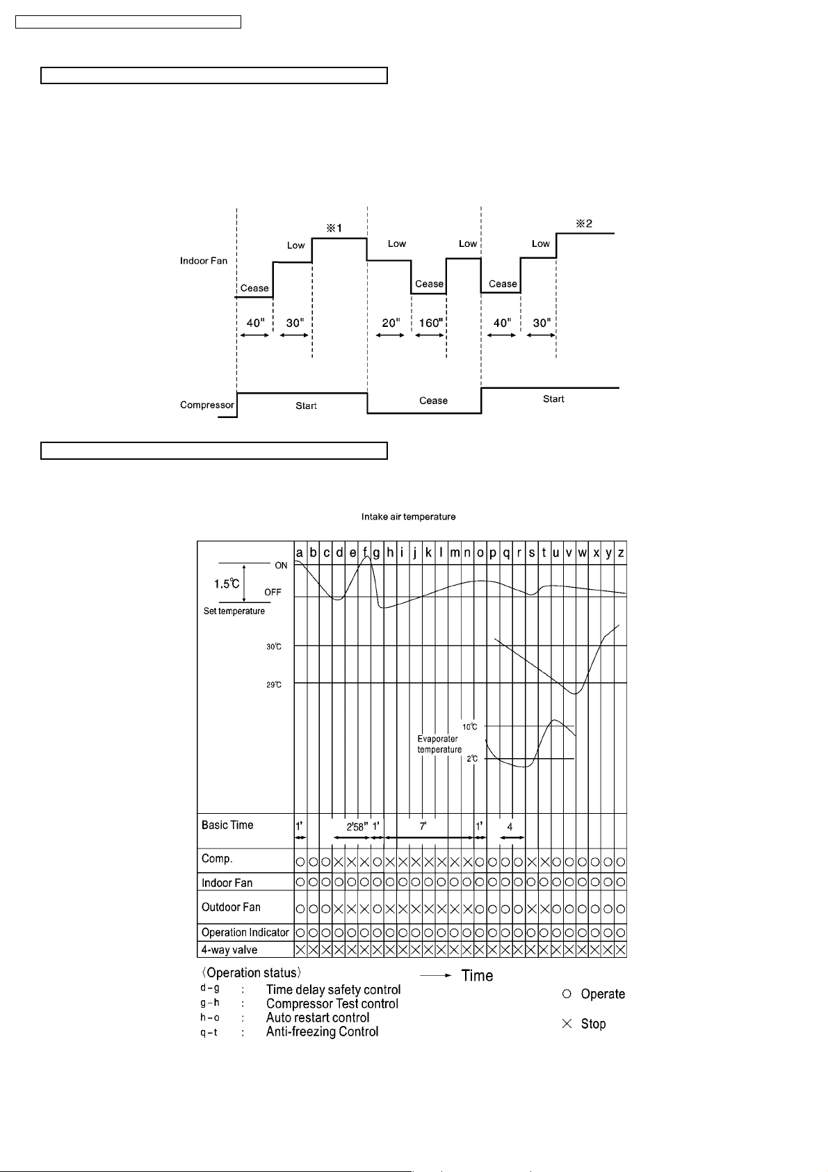
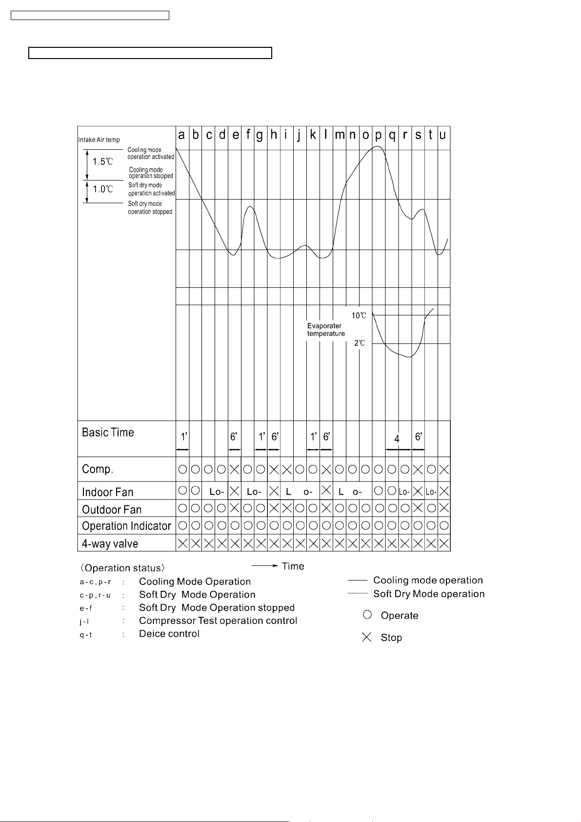
Time Graph for cooling Operation
16
CS-PC9CKV CU-PC9CKV / CS-PC12CKV CU-PC12C KV
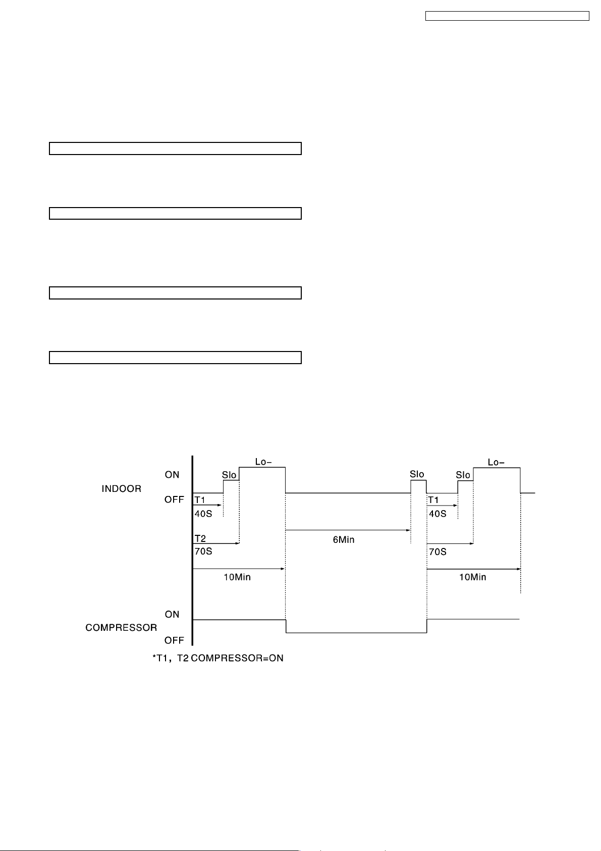
7.2. Soft Dry Mode Operation
•
•
When selecting Soft Dry mode operation, the operation will be cooling until the room temperature reaches the set temp on the
• •
remote control, and then Soft Dry will be activated. (During Soft Dry Mode the fan of indoor unit will operate at super low speed.)
•
•
Once soft Dry mode operation is turned off, indoor fan, compressor and outdoor fan will stop for 6 minutes.
• •
Time Delay Safety Protection
•
•
During cooling mode operation, if the compressor ceased, it will not restart within 3 minutes.
• •
Anti Freezing Control
•
•
Same as the denotation in Cooling Operation. (P.15)
• •
(During Soft Dry Mode Operation, compressor will stop for at least 6 min.)
Anti-reverse Control
•
•
Same as the denotation in Cooling Operation. (P.15)
• •
Automatic Fan Speed
During Soft Dry Operation, use remote control to select Auto Fan Speed mode.
•
•
Indoor Fan Speed is at super low.
• •
•
•
Deodorization control.
• •
17
CS-PC9CKV CU-PC9CKV / CS-PC12CKV CU-PC12C KV
Time Graph for soft dry operation
18
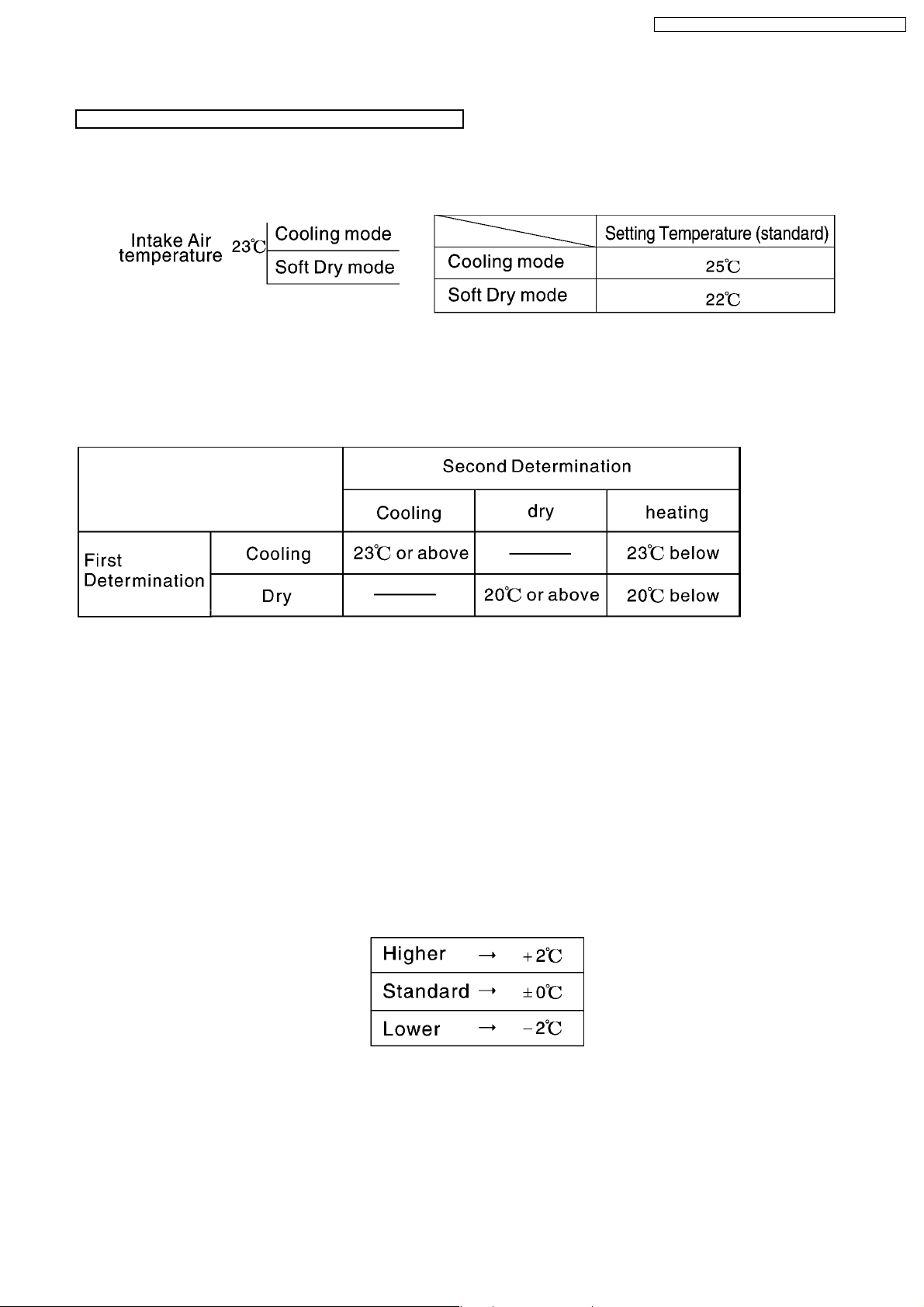
7.3. Automatic Mode Operation
Standard for determining operation mode
First Determination:
Second Determination:
One hour after the above determination, the unit will operate according to the table below.
CS-PC9CKV CU-PC9CKV / CS-PC12CKV CU-PC12C KV
1. Indoor fan operates at super low speed for 20 seconds.
2. After judging indoor air temperature, the operation is determined and operation continued at the mode determined.
3. After the operation mode has been determined, the mode does not change. However, Soft Dry mode operation includes cooling
mode operation.
4. If automatic mode operation is started while the unit is operating, operation will continue.
If current operation is in cooling mode (including the cooling mode operation when is a part of Soft Dry mode operation) it will
be maintained, and if current operation is not cooling mode, the appropriate operation mode is determined for 20 seconds at
super slow fan speed. Then the selected mode will continue.
5. Room temperature adjustment
19
 Loading...