

Panasonic CS-MVG103KE, CU-MVG153KE Service Manual
Order number RAC9911058C2
Room Air Conditioners
CS-MVG103KE
CU-MVG153KE
© 1999 Matsushita Electric Industrial Co., Ltd. All
rights reserved. Unauthorized copying and
distribution is a violation of law.
CS-MVG103KE / CU-MVG153KE
CONTENTS
Page Page
1 Features 2
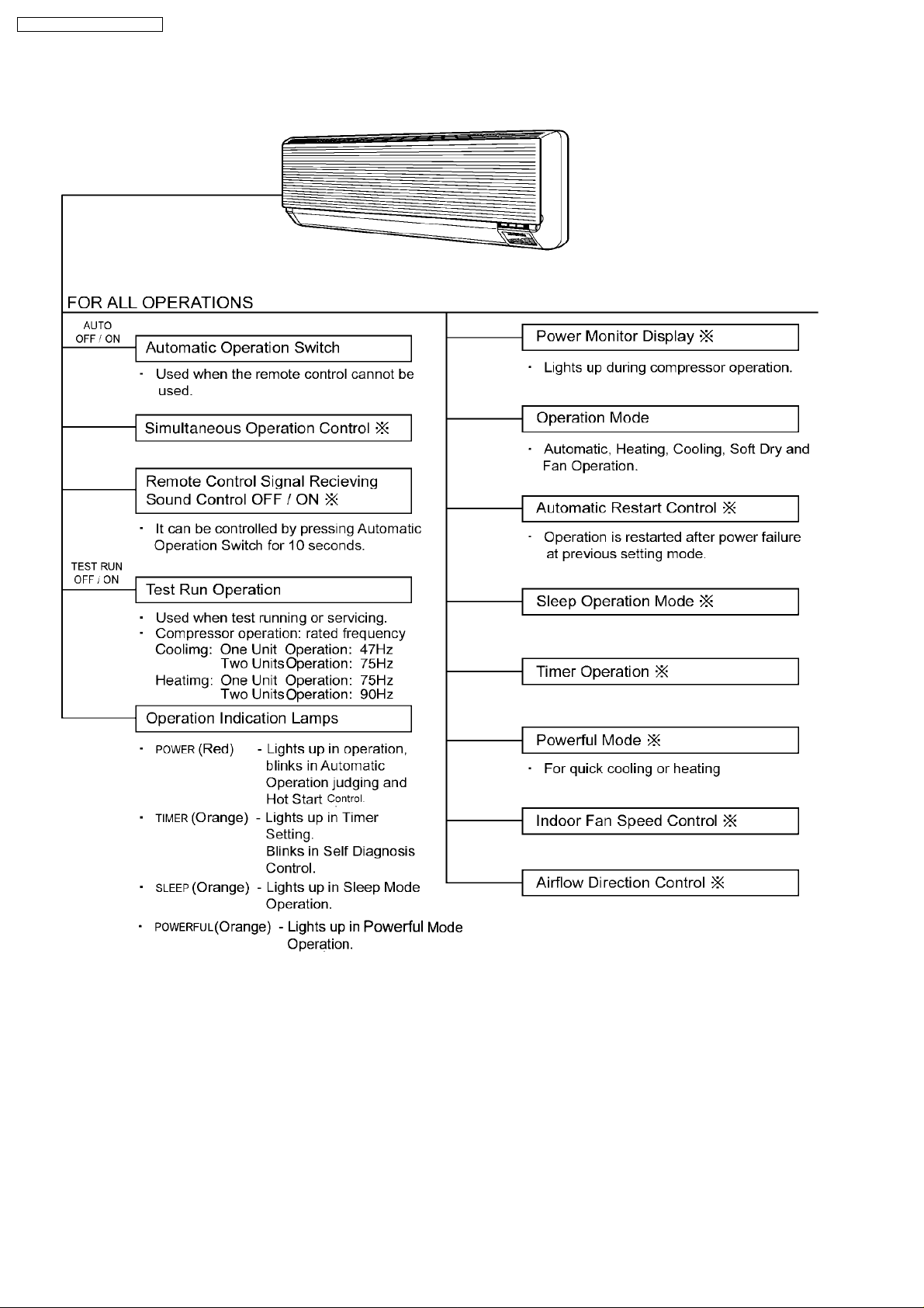
2 Functions
2.1. REMOTE CONTROL
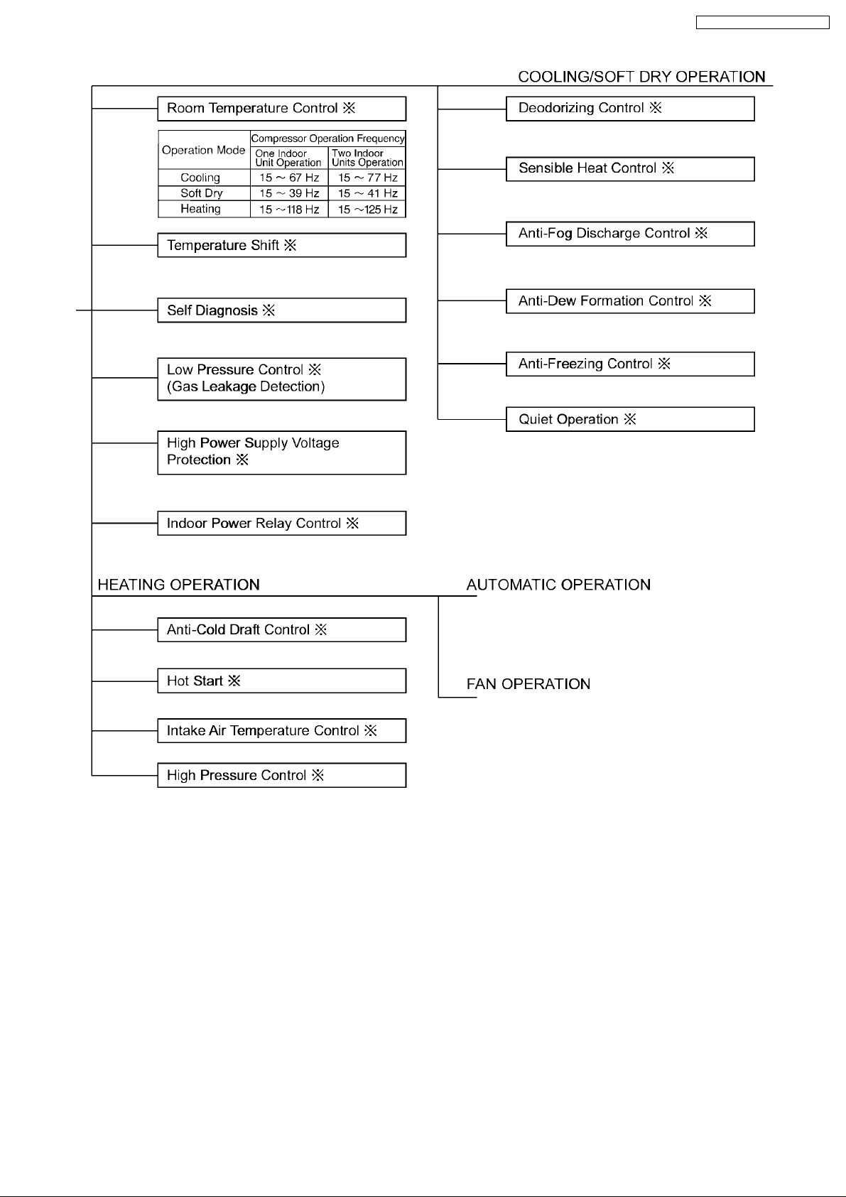
2.2. INDOOR UNIT
2.3. OUTDOOR UNIT
3 Product Specifications
4 Dimensions
4.1. CS-MVG103KE (INDOOR UNIT)
4.2. CU-MVG153KE (OUTDOOR UNIT)
5 Refrigeration Cycle Diagram
6 Block Diagram
7 Wiring Diagram
7.1. CS-MVG103KE ( INDOOR UNIT )
7.2. CU-MVG153KE ( OUTDOOR UNIT )
8 Operation Details (FUNCTIONS)
8.1. SIMULTANEOUS OPERATION CONTROL
8.2. TEMPERATURE SHIFT
8.3. COMPRESSOR OPERATING FREQUENCY OPERATION
8.4. COOLING OPERATION
8.5. SOFT DRY OPERATION
8.6. HEATING OPERATION
8.7. FAN OPERATION
8.8. AUTOMATIC OPERATION
8.9. INDOOR FAN SPEED CONTROL
8.10. OUTDOOR FAN CONTROL
8.11. AIRFLOW DIRECTION
8.12. QUIET OPERATION
8.13. POWERFUL MODE OPERATION
8.14. SLEEP MODE OPERATION
8.15. DELAY ON TIMER CONTROL
8.16. AUTO RESTART CONTROL
8.17. POWER MONITOR DISPLAY
8.18. REMOTE CONTROL SIGNAL RECEIVING SOUND
ON/OFF
9 Operation Details (PROTECTION)
9.1. PROTECTION CONTROL FOR ALL OPERATIONS
10
11
12
13
13
14
15
15
16
17
18
20
21
25
25
27
29
29
31
31
32
33
33
34
34
35
35
3
3
4
6
7
9
9
9.2. PROTECTION CONTROL FOR COOLING & SOFT DRY
9.3. PROTECTION CONTROL FOR HEATING OPERATION
10 Installation And Servicing Air Conditioner Using R410A
10.1. OUTLINE
10.2. TOOLS FOR INSTALLING/SERVICING REFRIGERANT
PIPING
10.3. REFRIGERANT PIPING WORK
10.4. INSTALLATION, TRANSFERRING, SERVICING
11 Installation Information
11.1. ATTACHED ACCESSORIES
11.2. SELECT THE BEST LOCATION
11.3. INDOOR/OUTDOOR UNIT INSTALLATION DIAGRAM
11.4. CONNECTION PIPES FOR AIR CONDITIONER UNITS
WITH R410A
11.5. NOTE
12 Servicing Information
12.1. TROUBLESHOOTING
12.2. SELF DIAGNOSIS DISPLAY
12.3. REMOTE CONTROL
12.4. DISASSEMBLY OF PARTS
13 Technical Data
13.1. OPERATION CHARACTERISTICS
14 Electronic Circuit Diagram
14.1. HOW TO USE ELECTRONIC CIRCUIT DIAGRAM
14.2. TIMER TABLE
14.3. INDOOR UNIT
14.4. OUTDOOR UNIT
14.5. REMOTE CONTROLLER
15 Printed Circuit Board
15.1. INDOOR UNIT
15.2. OUTDOOR UNIT / MAIN PCB
15.3. OUTDOOR UNIT / TRANSISTOR MODULE
16 Exploded View & Replacement Parts List
16.1. CS-MVG103KE
16.2. CU-MVG153KE
17 Electronic Parts List
39
40
41
41
42
46
48
52
52
52
54
55
55
56
56
58
60
61
69
69
71
71
71
72
74
76
77
77
79
81
82
82
84
86
1 Features
Product
·
−
−
Powerful Mode for quick cool/heat
− −
−
−
Compressor operating frequency control to maintain
− −
desired room temperature
−
−
Automatic Restart after power failure
− −
−
−
Washable front panel
− −
−
−
Power Monitor Display
− −
Serviceability
·
−
−
Self diagnosis
− −
−
−
Test Run at both Cooling and Heating rated frequency
− −
Quality Improvement
·
−
−
High power supply voltage protection
− −
−
−
Low power supply voltage protection
− −
−
−
Gas leakage detection
− −
2

2 Functions
2.1. REMOTE CONTROL
CS-MVG103KE / CU-MVG153KE
3
CS-MVG103KE / CU-MVG153KE
2.2. INDOOR UNIT
4
CS-MVG103KE / CU-MVG153KE
5

CS-MVG103KE / CU-MVG153KE
2.3. OUTDOOR UNIT
6
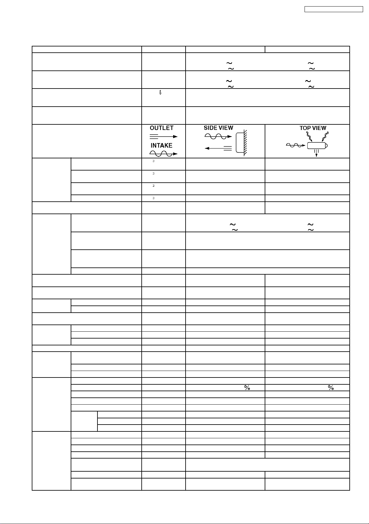
3 Product Specifications
Unit CS-MVG103KE CU-MVG153KE
Cooling Capacity
kW
Btu/h
Heating Capacity
kW
Btu/h
Moisture Removal /h
Pint/h
Power Source Phase
V
Cycle
Airflow Method
CS-MVG103KE / CU-MVG153KE
(1 unit) (2 units)
2.8(0.7 3.5) 2.25(0.45 2.3)
9,500(2,400 11,900) 7,650(1,500 7,850)
(1 unit) (2 units)
4.0(0.7 4.3) 2.6(0.45 3.05) x 2
13,600(2,400
14,700) 8,850(1,500 10,400) x 2
(1 unit) (2 units)
1.6 2.5
3.4 5.3
Single
230
50
x 2
x 2
Air Volume Indoor Air(Lo) m / min(cfm) Cooling ; 7.0(247)
Indoor Air(Me) m / min(cfm) Cooling ; 7.6(268)
Indoor Air(Hi) m / min(cfm) Cooling ; 8.3(293)
Outdoor Air m / min(cfm) - Hi; 30.0(1050)
Noise Level dB(A) Cooling ; High 39,Low 27
Electrical
Data
Piping Connection Port
(Flare piping)
Pipe Size
(Flare piping)
Drain
Hose
Power Cord length
Number of core-wire
Dimensions Height inch(mm) 10 - 31/32(279) 25 - 25/32(540)
Net Weight lb(kg) 20(9.0) 95(43)
Compressor Type - Rotary
Air Circulation Type Cross-flow Fan Propeller Fan
Heat
Exchange
Input
kW
Running Current
A
COP (1 unit) (2 units)
Starting Current A 6.50
inch
inch
inch
inch
Inner diameter mm 12 Length m 0.7 -
Width inch(mm) 31 - 15/32(799) 30 - 3/4(780)
Depth inch(mm) 7 - 15/32(190) 11 - 13/32(289)
Motor Type - Brushless(4-poles)
Rated Output W - 1,200
Material AS+Glass Fiber 30 AES+Giass Fiber 12
Motor Type Transiator(4-poles) Induction(6-poles)
Input W - 110
rated Output W 20 25
Fan
Speed
description Evaporator Condenser
Tube material Copper Copper
Fine material Aluminium Aluminium
Fine type Slit Fin Corrugated Fin
Row/Stage
FPI 21 17
Size(W x H x L) mm 600 x 252 x 25.4 673 x 504 x 18.2
Low Cool(Heat) rpm 880(970) Medium Cool(Heat) rpm 1,100(1,170) High Cool(Heat) rpm 1,290(1,310) 700
Heating ; 7.2(254)
Heating ; 7.8(275)
Heating ; 8.5(300)
heating ; High 39,Low 27
Cooling ; 770(250 1,100) 1,350(255 1,380)
Heating ;1,320(215 1,900) 1,280(220 1,800)
Cooling ;;3.70 ( max 5.40 ) 6.50 ( max 6.70 )
Heating 6.35 ( max 9.90 ) 6.15 ( max 9.90 )
Cooling ; 3.64 3.33
Heating ; 3.03 4.06
(1 unit) (2 units)
(1 unit) (2 units)
G ; Half Union 3/8”
L ; Half Union 1/4”
G(gas side) ; 3/8”
L(liquid side) ; 1/4”
-
-
(Plate fin configuration,forced draft)
2/14
G ; 3-Way valve 3/8”
L ; 2-Way valve 1/4”
L(liquid side) ; 1/4”
-
-
-
Cooling ; 46
Heating ; 47
G(gas side) ; 3/8”
-
-
(2 cylinder)
2/24
615 x 504 x 18.2
7
CS-MVG103KE / CU-MVG153KE
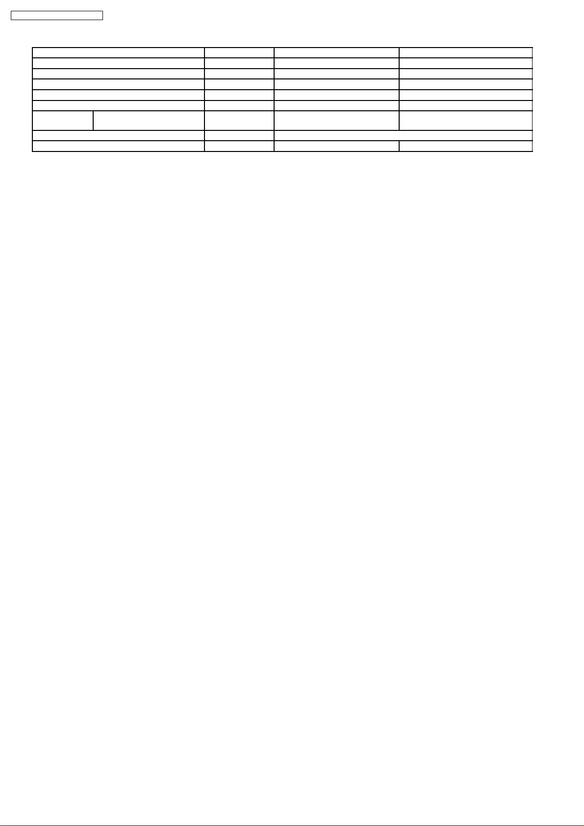
Unit CS-MVG103KE CU-MVG153KE
Refrigerant Control Device - Expansion Valve
refrigeration Oil (c.c) - RB88A(290)
Refrigerant(R410A) g(oz) - 1250(44.1)
Thermostat Electronic Control Protection Device Electronic Control
Air Filter Material
Capacity Control Expansion valve
Fan motor Capacitor µF,VAC - 2.0µF,400VAC
·
Specifications are subject to change without notice for further improvement.
style
P.P
Honeycomb
-
8
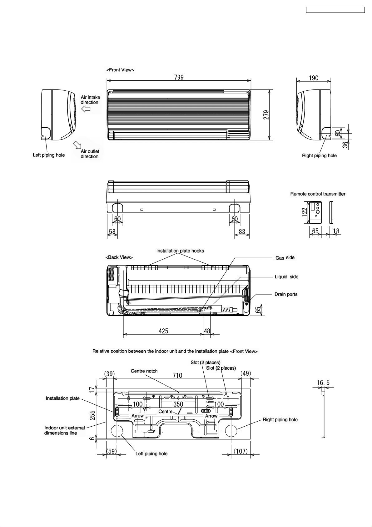
4 Dimensions
4.1. CS-MVG103KE (INDOOR UNIT)
CS-MVG103KE / CU-MVG153KE
9
CS-MVG103KE / CU-MVG153KE
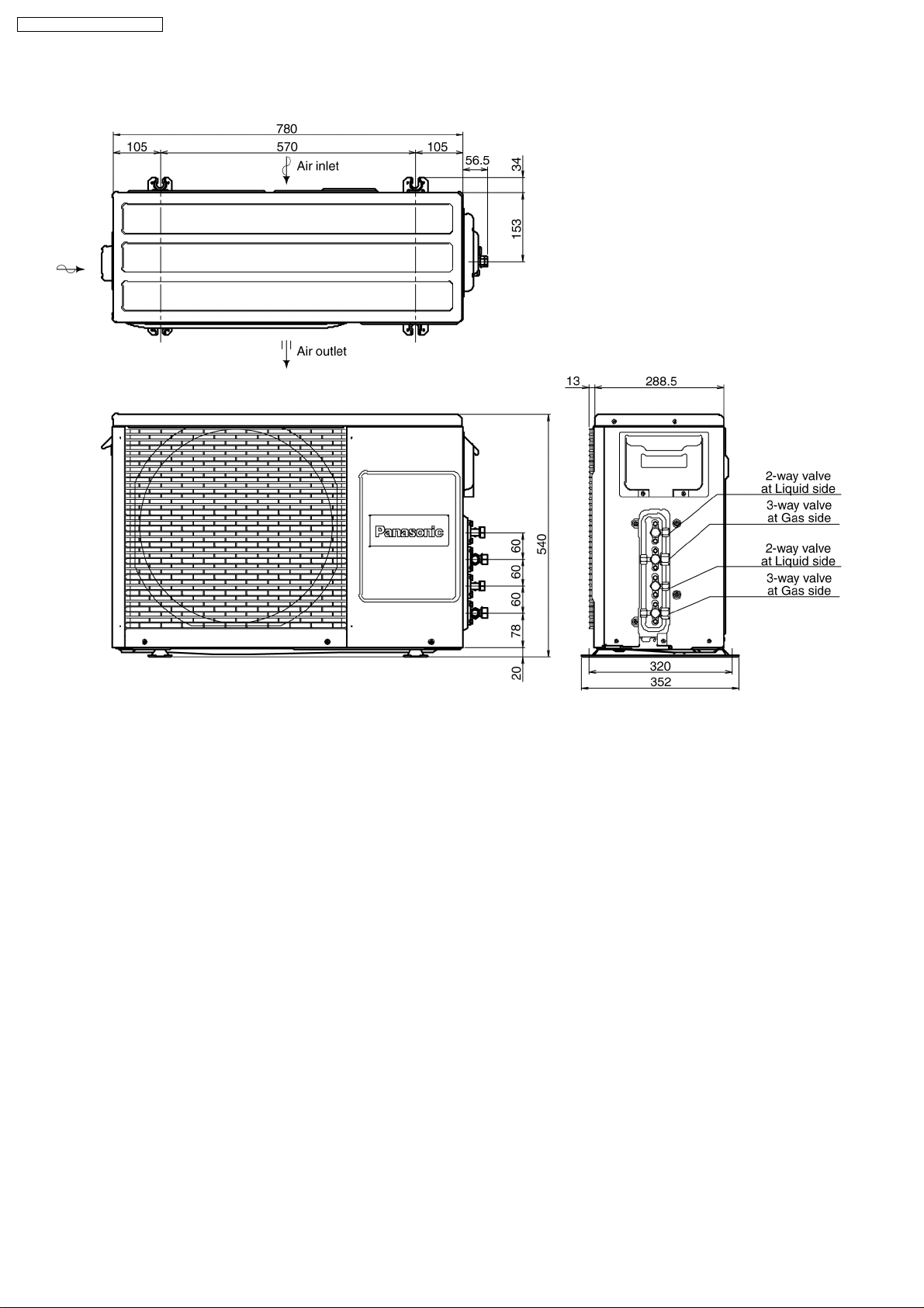
4.2. CU-MVG153KE (OUTDOOR UNIT)
10
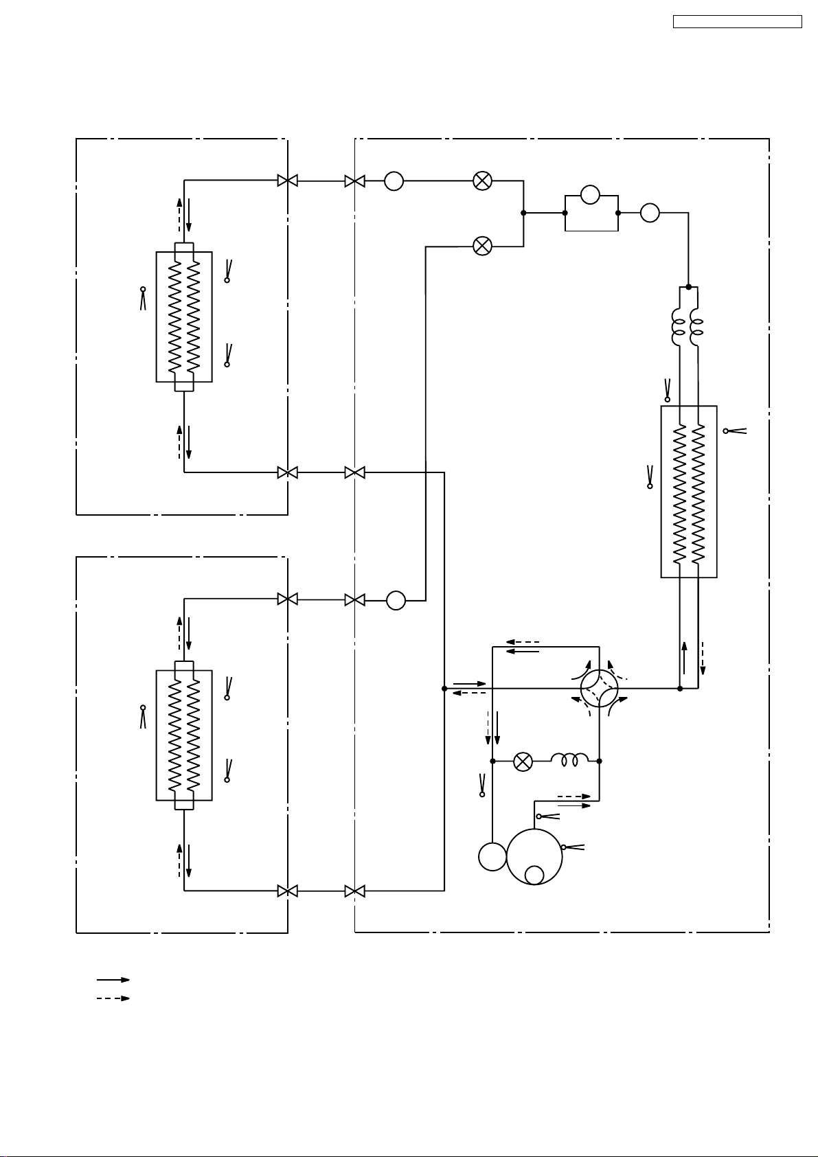
5 Refrigeration Cycle Diagram
4-WAY VAL VE
2-WAY
VALVE
PIPE
TEMP.
SENSOR
PIPE
TEMP.
SENSOR
SENSOR
TEMP.
INTAKE
PIPE
TEMP.
SENSOR
PIPE
TEMP.
SENSOR
INDOOR A
OUTDOOR
COOLING
HEATING
HEAT EXCHANGER
(EVAPORATOR)
HEAT EXCHANGER
(CONDENSER)
2-WAY
VALVE
VALVE
3-WAY
2-WAY
VALVE
VALVE
3-WAY
C1
STRAINER
C ; CAPILLARY TUBE
SENSOR
TEMP.
INTAKE
PIPE
TEMP.
SENSOR
PIPE
TEMP.
SENSOR
INDOOR B
HEAT EXCHANGER
(EVAPORATOR)
DISCHARGE TEMP
SENSOR
COMPRESSOR
COMPRESSOR
TEMP SENSOR
OUTDOOR AIR
TEMP SENSOR
DRYER
STRAINER
STRAINER
EXPANSION
VALVE (A)
EXPANSION
VALVE (B)
SUCTION
TEMP.
SENSOR
CS-MVG103KE / CU-MVG153KE
11

6 Block Diagram
INDOOR UNIT A OUTDOOR UNIT
WIRELESS
REMOTE CONTROL
TRANSMITTER
FUSE
(3.15A)
CS-MVG103KE / CU-MVG153KE
OUITDOOR
POWER
SUPPLY
SINGLE
PHASE
230V 50Hz
1 2
FUSE
(20A)
1
1
C.T.
RY-AC
PTC
RY-PWR
12
RECEIVER
P.C.B.
INCIDATOR
P.C.B.
FAN
MOTOR
LOUVER
MOTOR
FM
3C
9C
3C
5C
ELECTRONIC
CONTROLLER
TERNINAL
THERMAL
FUSE 102
INDOOR UNIT B
SAME AS
UNIT A
RY-L
RY-2CV
RY-HOT
DIODE
-
4-WAY
NOISE FILLTER
ELECTRONIC
CONTROLLER
2
2
3
3
1
1
2
2
3
3
VALVE
2-WAY
VALVE
MOTOR
FM
FAN
REACTOR
++
+
NOISE FILLTER
5C
5C
EXP.VALVE(A)
EXP.VALVE(B)
COMPRESSOR
Indicates the electronic control unit.
"C" Indicates the number of core wires. (Example:5C=5 core wires).
7 Wiring Diagram
Y
7.1. CS-MVG103KE ( INDOOR UNIT )
PUMP DOWN SW.
PUMP DOWN SW.
( TEST RUN)
( TEST RUN)
FUSE
FUSE
T 3. 15A L 250V
T 3. 15A L 250V
1
1
1
1
EL ECTRONIC
EL ECTRONIC
CONTROLLER
CONTROLLER
ZNR
ZNR
AUTO SW.
AUTO SW.
W
W
3
3
2
2
1
1
CS-MVG103KE / CU-MVG153KE
53
12
12
3
3
CN- MTR1( G)
CN- MTR1( G)
E
E
L
L
O
O
C
C
R
R
(
(
C
C
W
W
W
W
W
W
53
1
1
RBY
RBY
L
L
E
E
W
W
I
I
R
R
E
E
E
E
M
M
O
O
T
T
R
R
R
R
C
C
O
O
N
N
T
T
N
N
R
R
O
O
E
E
C
C
T
T
L
L
R
R
O
O
L
L
N
N
T
T
E
E
V
V
E
E
I
I
E
E
C
C
R
R
C
C
V
V
(
(
N
N
-
-
3
3
2
2
1
1
MOT OR
MOT OR
S
S
S
S
E
E
O
O
L
L
C
C
I
I
E
E
R
R
R
R
)
)
W
W
)
)
/G
/G
123
123
TERMINAL
TERMINAL
TO OUT DOOR UNIT
TO OUT DOOR UNIT
16
16
16
16
TERM INAL
TERM INAL
COMPLETE
COMPLETE
THERMAL FUSE
THERMAL FUSE
102 C(3A)
102 C(3A)
CN- RCV1 ( )
CN- RCV1 ( )
SENSOR 2
SENSOR 2
(PIPE TEMP.2)
CN- STM1 (W)
CN- STM1 (W)
2435
1
2435
1
O
O
P
CN-PWR1( B)
CN-PWR1( B)
REMARKS
REMARKS
B : BL UE BR:BROWN W : WHI T E G:GREEN
B : BL UE BR:BROWN W : WHI T E G:GREEN
P : PINK Y: YELLOW O : ORANGE
P : PINK Y: YELLOW O : ORANGE
BL : BL ACK R: RED Y/ G : YEL LOW/GREEN
BL : BL ACK R: RED Y/ G : YEL LOW/GREEN
P
MOTOR
MOTOR
LOUVER
LOUVER
CN- DI SP2(W)
CN- DI SP2(W)
CN-DISP1(W)
CN-DISP1(W)
DISPLAY, SEL F - DIAGNOSIS
DISPLAY, SEL F - DIAGNOSIS
POW E R MONITO R DISPLAY
POW E R MONITO R DISPLAY
BRR
Y
BRR
Y
15
15
65
4
4
321
321
6789
6789
798
65
798
WWWW
WWWW
WWWW
WWWW
W
W
12345
12345
6
6
5
5
4
4
321
321
CN -TH1 (W)
CN -TH1 (W)
(PIPE TEMP.2)
SENSOR 1
SENSOR 1
( PI PE T EMP. 1)
( PI PE T EMP. 1)
SEN SOR
SEN SOR
(AIR TEMP.)
(AIR TEMP.)
13

C
CS-MVG103KE / CU-MVG153KE
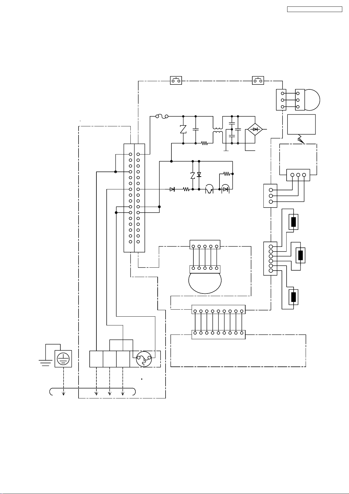
7.2. CU-MVG153KE ( OUTDOOR UNIT )
230V/50Hz
SINGLE PHASE
1
BL
FUSE
250V/ 20A
BL
GG
6
7
9
8
1110
BR
-
+
CAPACITOR
OR
R
BL
Y
B
THE PRENTHESIZED
LETTER IS INDICATED
ON TERM I NAL COVER.
R
TRADE MARK
COMP. TERMINAL
R
U
B
V
Y
OMPRESSER
W
TERMINAL
2
WH
B
BL
420V 750 F
R
CAPACITOR
WH
REACTOR
251
43
175V 45 F
BL
-
+
420V 750 F
R
N
P
TO
INDOOR UNIT A
TERMINAL TERMINAL
1
2
3
BL
B
NOISE
FILTER
(BLUE)
(BLACK)
WH
WH
B
BR
BR
-
PTC
AC9
(BROWN)
Y
DIODE
+
SENSOR
AI R T EMP.
SENSOR
PI PE T EMP.
SENSOR
COMP. TEMP.
SENSOR
PIPE TEMP.
CN-V
CN- U
(BLUE)
(RED)
31
R
31
31
CN- U
CN-V
(RED)
(BLUE)
(YELLOW)
1
PBLB
(YELL OW)
CN- W
Y
3131
CN- W
AC10
(YELLOW)
V
TRANSISTOR COMPLETE
TO
INDOOR UNIT B
123
BL
AC1
AC2
AC3
(GRAY)
GR
(WHITE)
1
2
3
4
GR
1
GR
2
1
3
CN-L
(WHITE)
ORYBRRGRPV
GR
421
CN-L
(WHITE)
CN- ROOM B
(GREEN)
FUSE T5. 0A
L250V
+
AC5
RY- AC
L
P
RY- PWR
L
P
RY- L
CN- TH1
(YELLOW)
CN- TANK
(BLUE)
EL ECT RONIC
CONTROL UNIT
CN- T H2
(GREEN)
CN- PW M
(WHIT E)
78654312431
B
876543 1
CN-PWM
(WHIT E)
2
OR
2
B: BLUE
BL : BL ACK
BR: BROWN
G: GREEN
R: RED
WH: WHITE
Y: YELL OW
RBL
WH
OR
GR
1
FUSE T3. 15A
L250V
CT
CR101
RY- HOT
CR102
RY- 2CV
CR103
CN-DIS
(WHITE)
BR
31
SENSOR
PIPE TEMP.
CN-TH3
(YELLOW )
REMARKS
1
CN- HOT
(YELL OW)
CN- 2 CV
(WHITE)
C- FM
CN - F M
(GREEN)
31
SENSOR
AIR T EMP.
GR: GRAY
OR: ORANGE
P: PINK
V: VIOLET
CN-ROOM A
(BLUE)
33
BL
1
BL
3
(4-WAY
B
1
B
3
(2-WAY
Y
5
R
3
B
1
1
2
3
4
5
6
CN- EVA(WHITE)
EXP.
1
2
3
4
5
6
CN-EVB(YELLOW)
EXP. VALVE
COIL
COIL
MOT E R
OR
R
Y
BL
GR
OR
R
Y
BL
GR
VALVE)
VALVE)
FAN
COIL
EXP.
VALVE
VALVE
COIL
EXP.
VALVE
Resistance of Outdoor Fan Motor Windings
CONNECTION
YELLOW -RED
YELLOW - BLUE
CWA951029
257.2
265.2
( )
Resistance of Compressor Windings
CONNECTION
U-V
U-W
V-W
( )
1.0
1.0
1.0
14

8 Operation Details (FUNCTIONS)
8.1. SIMULTANEOUS OPERATION CONTROL
CS-MVG103KE / CU-MVG153KE
15
CS-MVG103KE / CU-MVG153KE
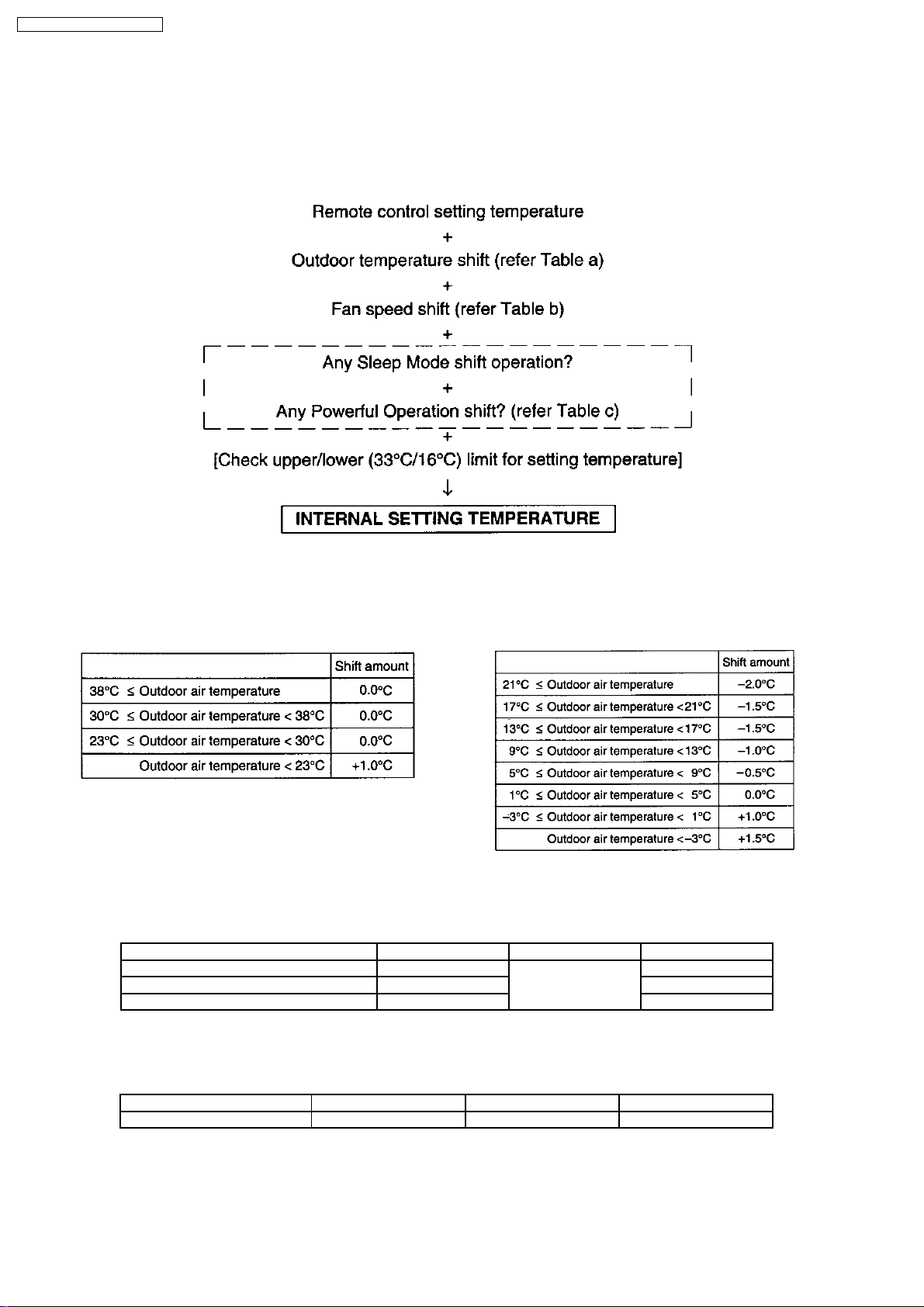
8.2. TEMPERATURE SHIFT
Once the operation starts, the remote control setting temperature will be shifted internally based on the setting fan speed and
outdoor air temperature. In addition, if Sleep Mode or Powerful Mode are set, the temperature shift will be carried out.
Setting of internal Setting Temperature
The internal setting temperature can be decided as follows:
8.2.1. Table a
Setting Temperature Shift based on outdoor air temperature.
1. Cooling, Soft Dry 2. Heating
8.2.2. Table b
Setting Temperature Shift based on fan speed.
Remote control setting fan speed Cooling Dry Heating
Lo +1.0°C +1.0°C +1.0°C
Me-, Me, Me+, Auto fan speed +1.0°C +1.0°C
Hi +1.0°C +1.0°C
8.2.3. Table c
Powerful Mode Shift
Cooling Dry Heating
Powerful -4.0°C -3.0°C +6.0°C
16
CS-MVG103KE / CU-MVG153KE
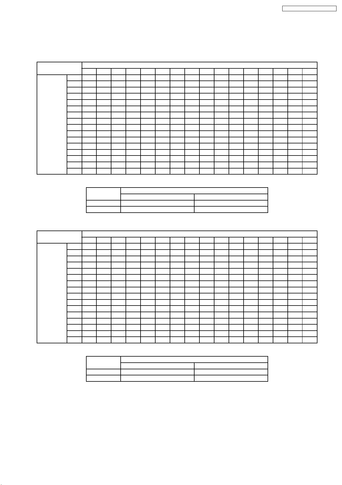
8.3. COMPRESSOR OPERATING FREQUENCY OPERATION
Compressor Operation Frequency According to Comp. Operation Frequency Command Number(INDOOR UNIT)
8.3.1. Cooling & Soft Dry
(Unit : Hz)
Comp.
Operation
Frequency
Command
Number of
Indoor Unit B
0 1 2 3 4 5 6 7 8 9 10 11 12 13 14 15
0 0 15 15 15 15 15 22 30 39 45 47 65 67 67 67 67
1 30 30 39 43 45 47 50 52 56 57 61 61 61 61 61
15
2 30 30 39 43 45 47 50 52 56 57 61 61 61 61 61
15
3 39 39 41 45 47 48 52 54 57 59 63 63 63 63 63
15
4 15
5 15 45 45 47 50 52 54 57 59 63 65 68 68 68 68 68
6 22 47 47 48 52 54 56 59 61 65 67 70 70 70 70 70
7 30 50 50 52 56 57 59 63 65 68 70 74 74 74 74 74
8 39 52 52 54 57 59 61 65 67 70 72 75 75 75 75 75
9 45 56 56 57 61 63 65 68 70 74 75 75 75 75 75 75
10 47 57 57 59 63 65 67 70 72 75 75 76 76 76 76 76
11 65 61 61 63 67 68 70 74 75 75 76 77 77 77 77 77
12 67 61 61 63 67 68 70 74 75 75 76 77 77 77 77 77
13 67 61 61 63 67 68 70 74 75 75 76 77 77 77 77 77
14 67 61 61 63 67 68 70 74 75 75 76 77 77 77 77 77
15 67 61 61 63 67 68 70 74 75 75 76 77 77 77 77 77
43 43 45 48 50 52 56 57 61 63 67 67 67 67 67
Rated and Maximum Operation frequency
Fc (10) 47 75
Fc max (15) 67 77
8.3.2. Heating
Comp.Operation Frequency Command Number of Indoor Unit A
Compressor Operation Frequency (Hz)
One Indoor Unit Operation Two Indoor Units Operation
(Unit : Hz)
Comp.
Operation
Frequency
Command
Number of
Indoor Unit B
0 1 2 3 4 5 6 7 8 9 10 11 12 13 14 15
0 0 15 25 35 45 55 55 65 69 74 75 93 106 118 118 118
1 15 45 55 65 69 71 72 74 75 77 77 78 81 83 83 83
2 25 55 65 69 71 72 74 75 77 78 78 80 83 84 84 84
3 35 65 69 71 72 74 75 77 78 80 80 81 84 86 86 86
4 45 69 71 72 74 75 77 78 80 81 81 83 86 87 87 87
5 55 71 72 74 75 77 78 80 81 83 83 84 87 89 89 89
6 55 72 74 75 77 78 80 81 83 84 84 86 89 90 90 90
7 65 74 75 77 78 80 81 83 84 86 86 87 90 92 92 92
8 69 75 77 78 80 81 83 84 86 87 87 89 92 93 93 93
9 74 77 78 80 81 83 84 86 87 89 89 90 93 94 94 94
10 75 77 78 80 81 83 84 86 87 89 90 92 93 100 100 100
11 93 78 80 81 83 84 86 87 89 90 92 93 94 106 106 106
12 106 81 83 84 86 87 89 90 92 93 93 94 106 112 112 112
13 118 83 84 86 87 89 90 92 93 94 100 106 112 125 125 125
14 118 83 84 86 87 89 90 92 93 94 100 106 112 125 125 125
15 118 83 84 86 87 89 90 92 93 94 100 106 112 125 125 125
Rated and Maximum Operation frequency
Fh (10) 75 90
Fh max (15) 118 125
Comp.Operation Frequency Command Number of Indoor Unit A
Compressor Operation Frequency (Hz)
One Indoor Unit Operation Two Indoor Units Operation
17
CS-MVG103KE / CU-MVG153KE
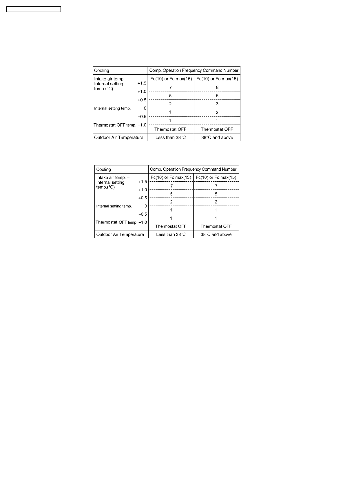
8.4. COOLING OPERATION
8.4.1. Room Temperature Control
1. When the remote control setting temperature is less than 24°C.
Refer to8.3.2. Compressor Operation Frequency
2. When the remote control setting temperature is 24°C and above.
Refer to8.3.1. Compressor Operation Frequency
· Thermostat OFF temperature = Thermostat ON temper ature.
· The Comp. Operation Frequency Command can be changed every 30 seconds.
· 30 minutes from the start of the operation, the compressor is operating at Fc max.
· The Thermostat OFF when the intake air temperature reaches 1°C below internal setting temperature and continues for 3
minutes.
· When the Thermostat of both Indoor Units OFF, the Compressor stops.
· When the compressor stops, it will not begin operation for 3 minutes. (Time Delay Safety Control)
· When the intake air temperature reaches the Compressor ON temperature, the Compressor starts operation.
· When the compressor stops, the outdoor fan motor stops 30 seconds later.
18
CS-MVG103KE / CU-MVG153KE
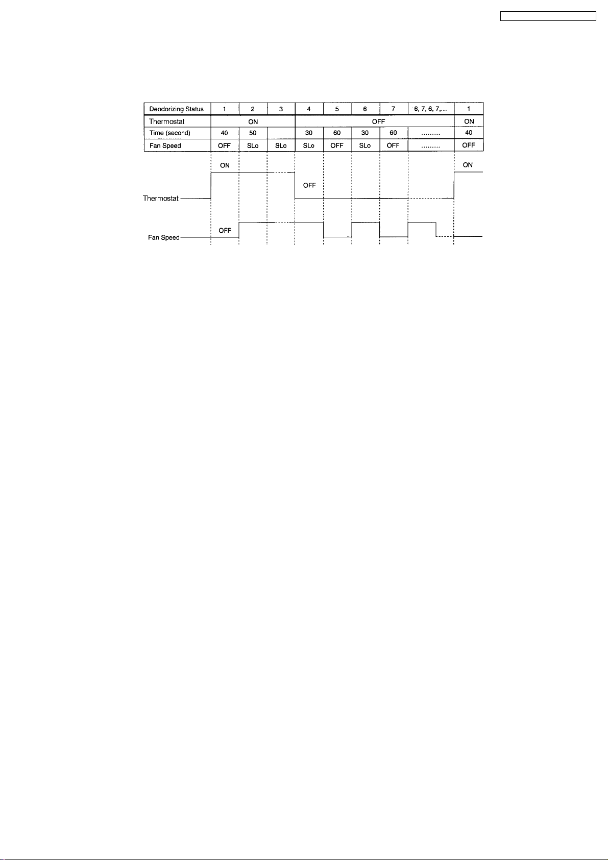
8.4.2. Deodorizing Control
· This control is available during automatic fan speed for Cooling and Soft Dry Operation. It is not available during anti-freezing
control.
· When the Thermostat ON operation, the deodorizing status starts from 1 → 2 → 3.
· When the Thermostat OFF operation, the deodorizing status starts from 4 → 5 → 6 → 7.
· If the Thermostat OFF operation after 3 minutes, the deodorizing status will start from 6.
8.4.3. Sensible Heat Control
· This control is to improve the feeling in high fan speed during low Comp. Operation Frequency Command Number. When the
Comp. Operation Frequency Command Number is less than 4, the fan speed will reduce. When the Comp. Operation
Frequency Command Number is above 5 continuously for 5 minutes, the fan speed will resume to normal condition.
19
CS-MVG103KE / CU-MVG153KE
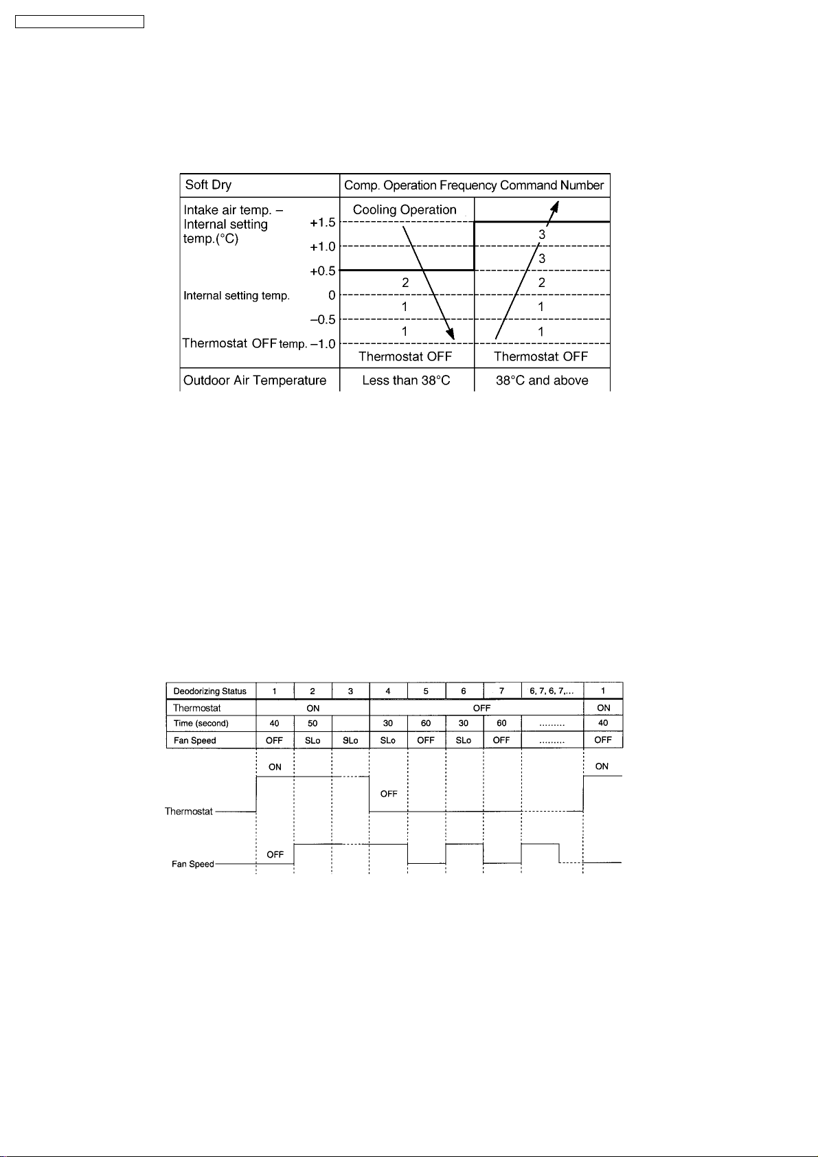
8.5. SOFT DRY OPERATION
8.5.1. Room Temperature Control
At the start of operation, cooling operation is running until the intake air temperature is 0.5°C higher than internal setting
temperature, then the operation will shift to Soft Dry with indoor fan speed SLo.
Refer to8.3.1. Compressor Operation Frequency
· Thermostat OFF temperature = Thermostat ON temper ature.
· The Comp. Operation Frequency Command can be changed every 30 seconds.
· 30 minutes from the start of the operation, the compressor is operating at Fc max.
· The Thermostat OFF when the intake air temperature reaches 1°C below internal setting temperature and continues for 3
minutes.
· When the Thermostat of both Indoor Units OFF, the Compressor stops.
· When the compressor stops, it will not begin operation for 3 minutes. (Time Delay Safety Control)
· When the intake air temperature reaches the Compressor ON temperature, the Compressor starts operation.
· When the compressor stops, the outdoor fan motor stops 30 seconds later.
8.5.2. Deodorizing Control
· This control is available during automatic fan speed for Cooling and Soft Dry Operation. It is not available during anti-freezing
control.
· When the Thermostat ON operation, the deodorizing status starts from 1 → 2 → 3.
· When the Thermostat OFF operation, the deodorizing status starts from 4 → 5 → 6 → 7.
· If the Thermostat OFF operation after 3 minutes, the deodorizing status will start from 6.
8.5.3. Sensible Heat Control
· This control is to improve the feeling in high fan speed during low Comp. Operation Frequency Command Number. When the
Comp. Operation Frequency Command Number is less than 4, the fan speed will reduce. When the Comp. Operation
Frequency Command Number is above 5 continuously for 5 minutes, the fan speed will resume to normal condition.
20
CS-MVG103KE / CU-MVG153KE
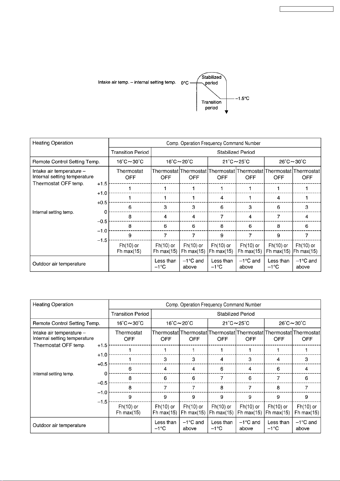
8.6. HEATING OPERATION
8.6.1. Room Temperature Control
· During heating operation, the room temperature control depends on intake air temperature and internal setting temperature.
Basically it can be divided into 2 periods as shown below:
1. When indoor fan speed is Medium or above.
Refer to8.3.2. Compressor Operation Frequency
2. When indoor fan speed is lower than Medium.
Refer to8.3.2. Compressor Operation Frequency
21
CS-MVG103KE / CU-MVG153KE
· Thermostat OFF temperature = Thermostat ON temper ature.
· The operation frequency changes every 30 seconds.
· When the difference of the intake air temperature and Internal setting temperature is -1.5°C or more, compressor will operate
at Fh continuously for 3 minutes and then change over to Fh max.
· The Thermostat OFF when the intake air temperature reaches 1.5°C above internal setting temperature and continues for 3
minutes.
· When the Thermostat of both Indoor Units OFF, the Compressor stops.
· When the compressor stops, it will not start operation for 3 minutes. (Time Delay Safety Control)
· When the intake air temperature decreases to the compre ssor ON temperature, the compressor starts immediately.
· When the compressor stops, the outdoor fan motor stops 30 seconds later.
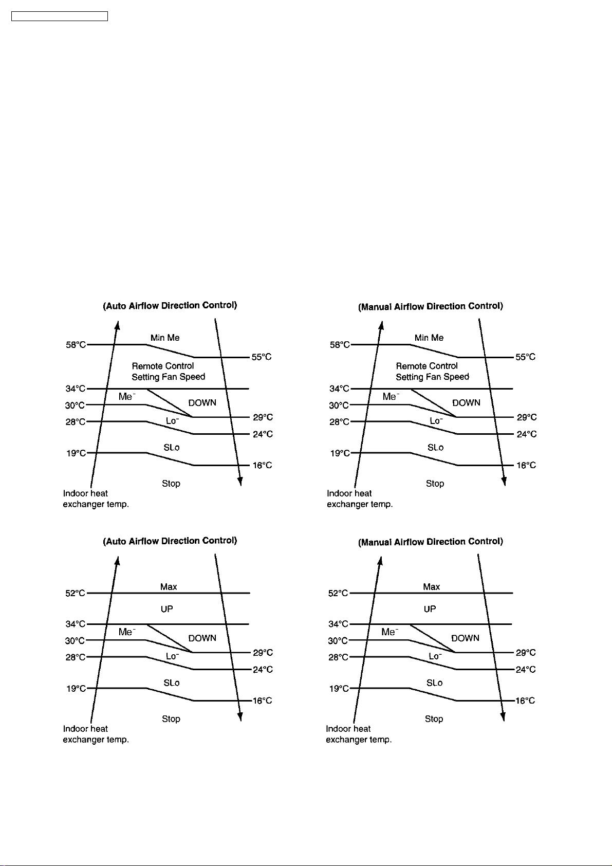
8.6.2. Anti Cold Draft Control
1. Indoor Fan Control
Indoor fan speed and airflow direction varies in accordance to the indoor heat exchanger temperature as shown below:
a. Manual Fan speed control
b. Auto Fan speed control
Note:
· UP means fan speed is increased by 1 rank.
· DOWN means fan speed is decreased by 1 rank.
· Max means fan speed is running at maximum auto fan speed.
22
CS-MVG103KE / CU-MVG153KE
2. Hot Start
· At the start of heating operation, the indoor fan stops and Comp. Operation Frequency Command Number at Fh max. This
is to heat up the indoor heat exchanger in order to avoid cold air discharged.
· Hot Start ends when
a. Indoor heat exchanger temperature reaches over 15°C
or
b. 4 minutes after heating operation starts
· After Hot Start operation, Comp. Operation Frequency Command Number at Fh max for 2 minutes.
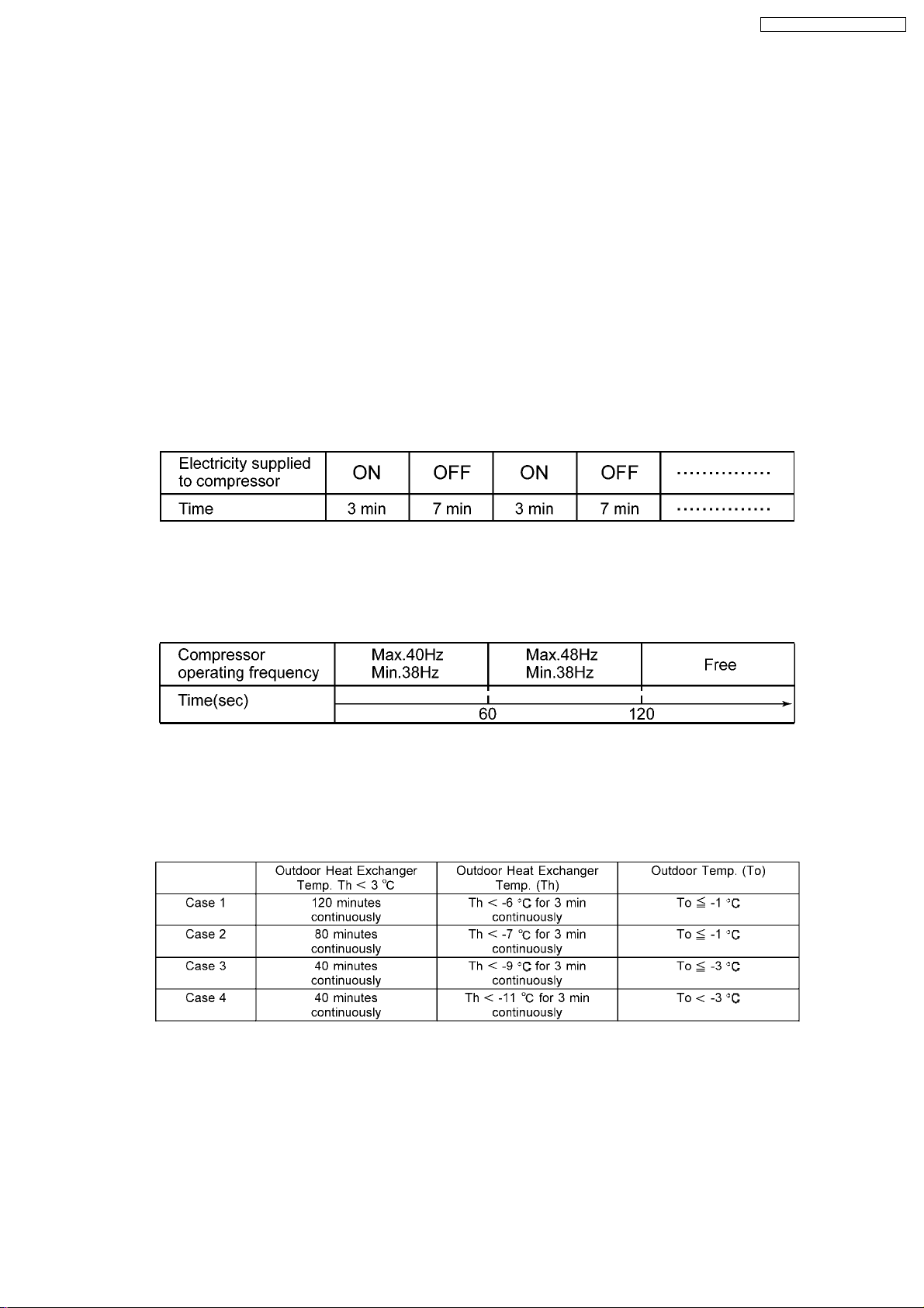
8.6.3. Standby Control
1. The purpose of Standby Control is to warm up the compressor when outdoor temperature is low.
the standby control will be activated when all of the followings occur.
· Unit is not operating.
· Compressor temperature is below 7°C.
2. When the standby control is activated, low electricity will be supplied to compressor for 3 minutes and stops for 7 minutes.
This condition is repeated until standby control is cancelled.It will consume about 35W of electric power.
3. Standby control will be cancelled when one of the following conditions occurs.
· Unit starts operation.
· Compressor temperature is over 9°C.
4. When the unit is switched on by the remote control, the compressor operates at frequency as shown in below:-
5. The standby control can be cancelled by cutting off the jumper wire on the outdoor electronic controller.
8.6.4. Deice Operation
Deice operation occurs when the deice operation starting signal is generated. This happens when one of the following conditions
occurs. However, the first deice operation will begin 1 hour after start of heating operation.
Note:
The above 4 cases are under compressor operating condition.
23
CS-MVG103KE / CU-MVG153KE
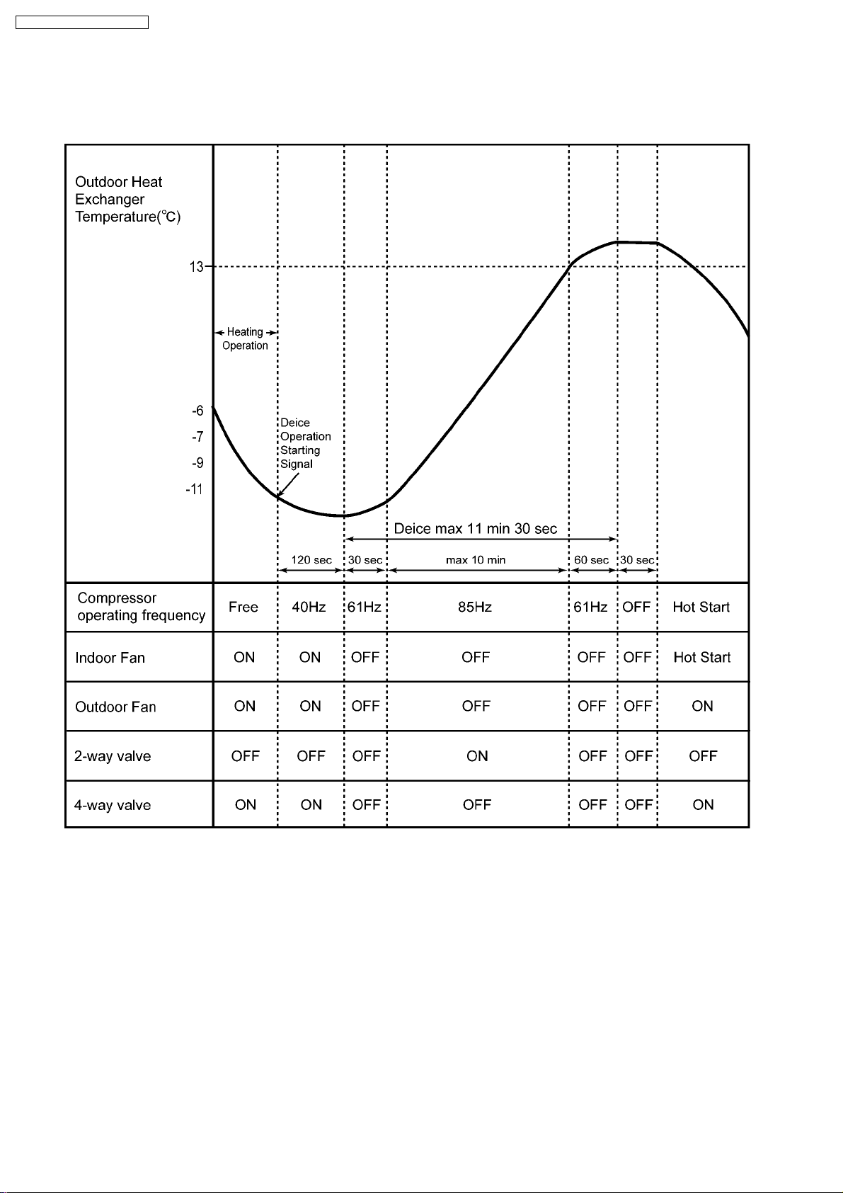
Deice Operation Time Chart
· Compressor frequency is set at 40Hz when the deice operation starting signal is generated.
· 120 seconds later deice operation starting signal is generated, indoor fan, outdoor fan, 4-way valve are turned off and
compressor operates at 61Hz for 30 seconds. (Deice operation starts)
· During deice operation, the compressor operating frequency is set at 85Hz.
· Deice will end when the outdoor heat exchanger temperature rises to 13°C or after 11 min 30sec.
24

CS-MVG103KE / CU-MVG153KE
8.7. FAN OPERATION
This operation is to enable the fan operation without compressor running. Timer operation is valid for fan operation.
8.8. AUTOMATIC OPERATION
When the Automatic mode is selected, the operation mode is decided in accordance to remote control setting temperature, intake
air temperature and outdoor air temperature.
· During judging the operati on mode, indoor fan is running at Lo-speed and outdoor fan at ON in order to sense the indoor intake
air temperature and outdoor air temperature for 20 seconds. At this time, Power LED is blinking. After the operation mode is
selected, Power LED light up.
There are 4 determination charts when automatic mode is selected.
25
CS-MVG103KE / CU-MVG153KE
Setting temp °C T1 T2 T3
18 and below +10 +8 -5
19 - 22 +8 +7 -7
23 - 26 +7 +6 -7
27 and above +6 +5 -8
Note:
Base temperature for T1 is 29 °C
Base temperature for T2 is 27 °C
Base temperature for T3 is 21 °C
· When the operation mode is changed over, the value for t1, t2 and t3 are shifted as follows:
Cooling/Soft dry → Heating: -2°C
Heating → Cooling/Soft dry: +2°C
· When the indoor intake air temperature is lower than 16°C, heating operation is immediately started.
· When the outdoor air temperature is more than 25°C, and the intake air temperature is over 16°C, cooling operation is
immediately started.
· The operation mode is judged every 3 hours.
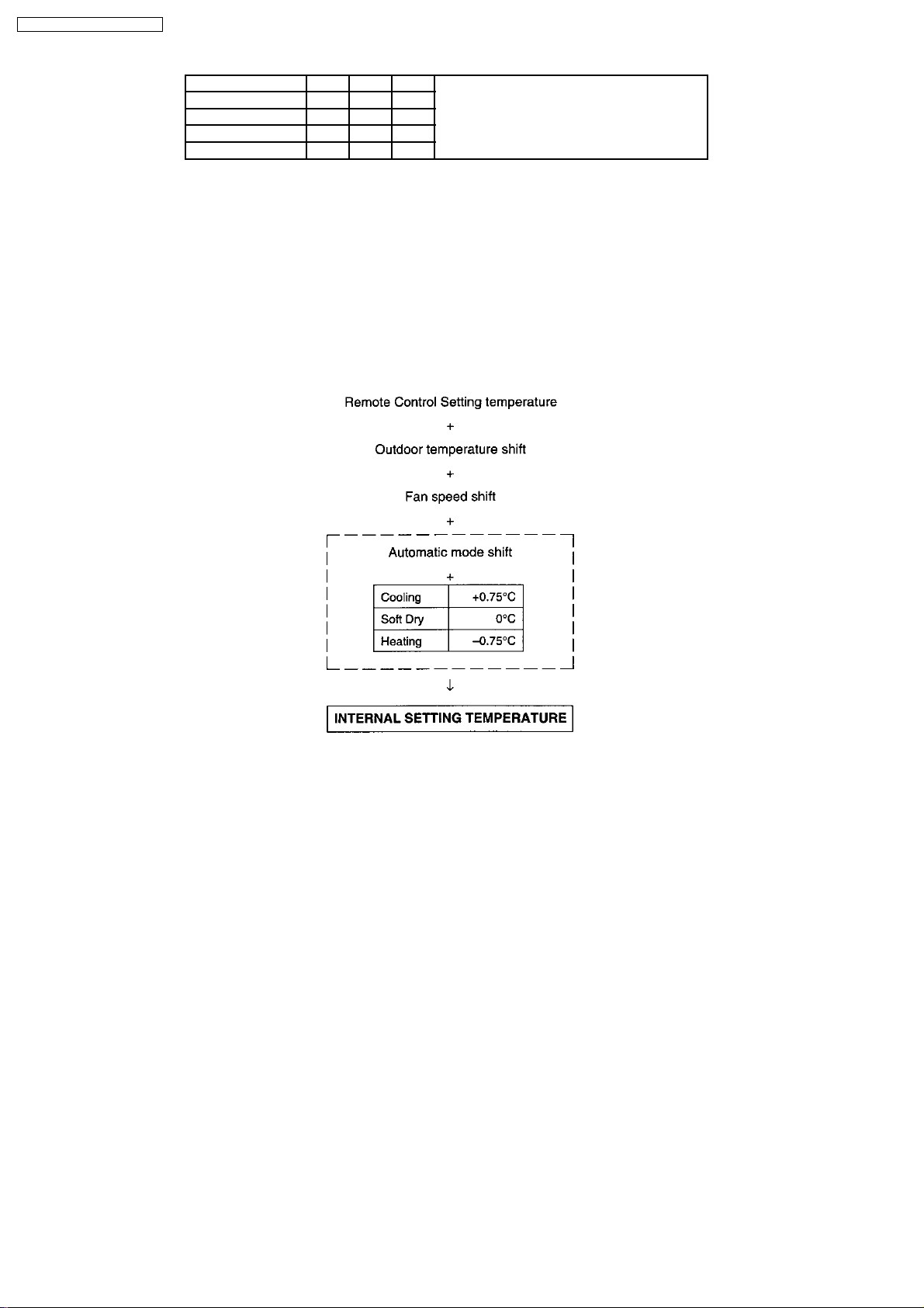
8.8.1. Temperature Shift
· When the operation mode (Heating, Cooling or Soft Dry) is decided, the internal setting temperature will shift as shown below:
26
8.9. INDOOR FAN SPEED CONTROL
CS-MVG103KE / CU-MVG153KE
Fan
speed
no.
0 OFF OFF OFF OFF OFF
2 13.0 SLO
3 13.7 Lo-
6 16.0 Lo
8 18.2 Lo
9 19.1
10 20.6 Me-
11 21.5 Auto
12 21.8 Me
13 22.7 Auto
14 23.6
15 23.9 Auto
16 24.5
17 25.1
19 26.0 Me+
21 26.6
22 27.2 Hi
27 29.5
28 29.9
30 33.2 SHI
31 33.8
Voltage
Supply to
Fan Motor
DC(V)
Cooling Soft
Manual Auto MAnual Auto
Fan
Fan
Fan
Dry
·
·
·
·
·
·
·
·
·
·
·
·
·
·
·
·
·
·
·
·
·
·
·
·
·
·
·
Remarks Heating Remarks
Deodorizing control
Sleep Mode
Auto operation mode
judgement
Quiet operation
Sensible Heat Control
On Timer preparatory
operation + Auto Fan
Manual Fan + Powerful
On Timer preparatory
operation + Manual Fan
+ powerful
Sensible Heat Control
Sensible Heat Control +
Auto Fan
Manual Fan + Powerful
On Timer preparatory
operation + Manual Fan
+ powerful
Sensible Heat Control +
Auto Fan
Sensible Heat Control
Auto Fan + Powerful
Manual Fan + Powerful
On Timer preparatory
operation + Manual Fan
+ powerful
Sensible Heat Control +
Auto Fan
Auto Fan + Powerful
Sensible Heat Control
Auto Fan + Powerful
Manual Fan + Powerful
On Timer preparatory
operation + Manual Fan
+ powerful
Test Run
SHi:Maximum Capacity
Operation
Manual Fan + Powerful
On Timer preparatory
operation + Manual Fan
+ powerful
Me- Auto
Me
Me+
Fan
(Min)
Auto
Fan
(Max.)
hot Start Control
·
Slo:Hot Start Control
·
Lo-:Hot Start Control
·
Sleep Mode
Thermo OFF
Anti Cold Draft
Control
On Timer preparatory
·
operation + Auto Fan
Auto Fan + Powerful
·
Manual Fan + Powerful
·
On Timer preparatory
·
operation + Manual Fan +
Powerful
Temporary Operation
·
Auto Fan + Powerful
·
Manual Fan + Powerful
·
On Timer preparatory
·
operation + Manual Fan +
Powerful
Test Run
·
SSHI:Maximum Capacity
·
Operation
27
 Loading...