

Panasonic CS-MC90KE, CU-MC140KE, CU-3MC200KE, CU-MC180KE Service Manual
ORDER NO. MAC9702008C2
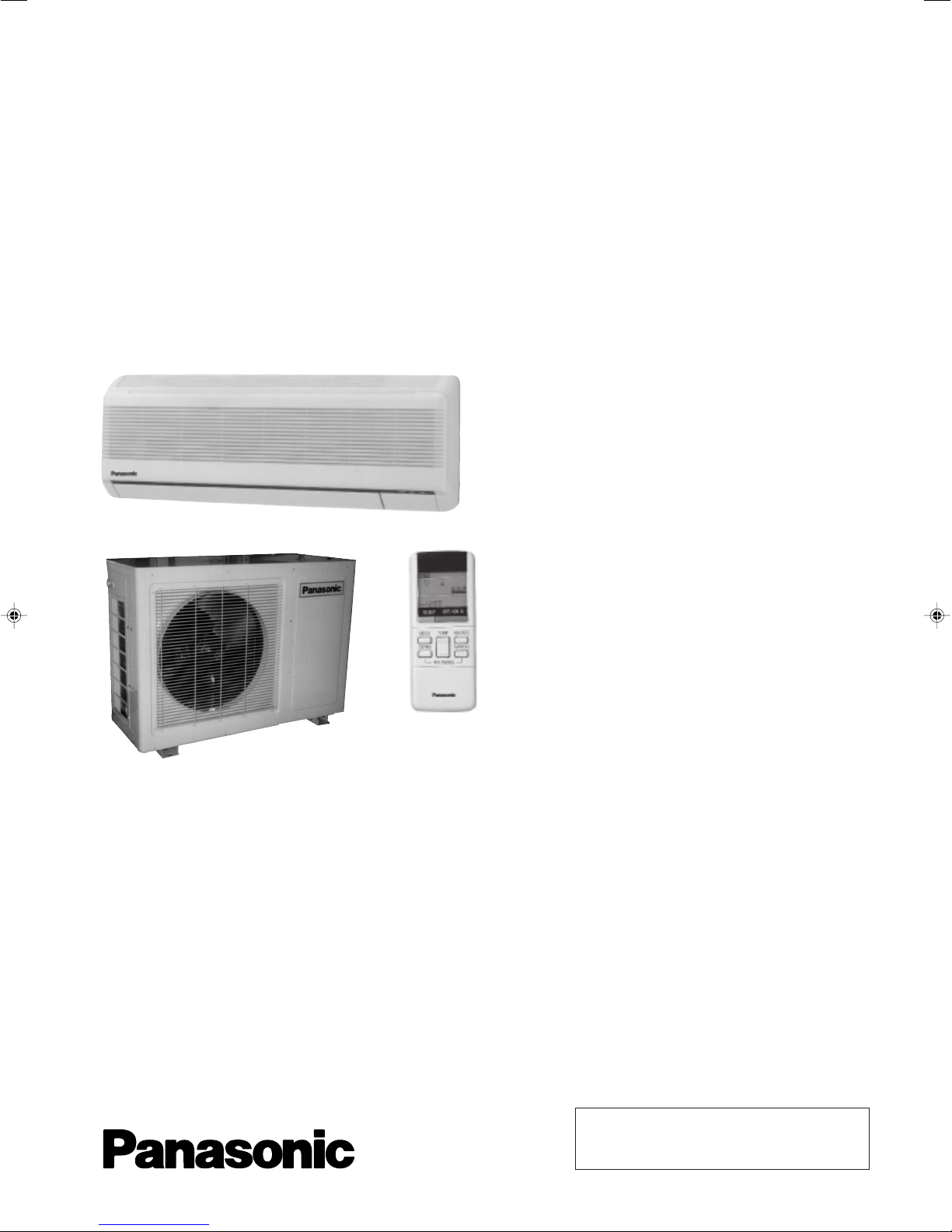
Service Manual
Multi-Split Air Conditioner
CS-MC90KE / CU-MC140KE
CS-MC90KE / CU-MC180KE
CS-MC90KE / CU-3MC200KE
Contents
● Features ..........................................................1
● Functions ...................................................2 – 4
● Product Specifications .............................5 – 10
● Dimensions ............................................11 – 12
● Refrigeration Cycle Diagram .........................13
● Block Diagram .......................................14 – 16
● Wiring Diagram ...................................... 17 – 19
● Operation Details ................................... 20 – 26
● Installation Information ..........................27 – 28
● 3-way Valve ...........................................29 – 35
● Servicing Information ............................. 36 – 39
● Troubleshooting Guide ..........................40 – 41
● Technical Data.......................................42 – 44
● Exploded View .............................45, 47, 49, 51
● Replacement Parts List ...............46, 48, 50, 52
● Electronic Parts List ...............................53 – 54
1997 Matsushita Industrial Corp. Sdn. Bhd.
(11969-T)
All rights reserved. Unauthorized copying and distribution is a violation of law.

CS-MC90KE
Electronic Parts List
<Model: CU-3MC200KE>
CWA741165 • ELECTRONIC CONTROLLER
SYMBOL
D1
D3
D4
D5
D8
D9
D12
D13
D14
D15
D16
D17
D18
D19
D20
D21
D22
D50
D51
FUSE
IC1
IC2
IC3
Q1
Q2
Q3
Q4
RY - C
RY - VA
RY - VB
SW1
ZNR
ZENER DIODE
DIODE
ZENER DIODE
PHOTO ISOLATOR
DIODE
PHOTO ISOLATOR
DIODE
DIODE
DIODE
DIODE
DIODE
DIODE
DIODE
DIODE
DIODE
DIODE
ZNR
ZNR
FUSE
IC
IC
IC
TRANSISTOR
TRANSISTOR
TRANSISTOR
TRANSISTOR
RELAY
RELAY
RELAY
SWITCH
DESCRIPTION & NAME
PART NO.
ERZC10DK471U
RD24EB - T1
1S1553 - TP3
RD12EB - T1
TLP521 - 1GB
D1N60 - 4070
TLP521 - 1GB
D1N60 - 4070
1SS133T - 77
1SS133T - 77
1S1553 - TP3
1S1553 - TP3
1S1553 - TP3
D1N60 - 4070
D1N60 - 4070
D1N60 - 4070
D1N60 - 4070
ERZC10DK471U
ERZC10DK471U
250VSC3A
TC4093BP
TC4069UBP
TA7555P
2SC1173 - 0
UN4215 - S - TA
UN4215 - S - TA
UN4215 - S - TA
G4FN - 24VDC or G4F - 24VDC
G4U - 24VDC or G4U - 1 - 24VDC
G4U - 24VDC or G4U - 1 - 24VDC
SSA042
(Note) ● All parts are supplied from ADC / JAPAN.
– 55 –
MAICO
Printed in Malaysia
P970602400YW

CS-MC90KE
This service information is designed for experienced repair technicians only and is not designed for use by the general public. It does not contain
warnings or cautions to advise non-technical individuals of potential dangers in attempting to service a product. Products powered by electricity
should be serviced or repaired only by experienced professional technicians. Any attempt to service or repair the product or products dealt with
in this service information by anyone else could result in serious injury or death.
Features
!
WARNING
!
PRECAUTION OF LOW TEMPERATURE
In order to avoid frostbite, be assured of no refrigerant leakage during the installation or repairing of refrigeration circuit.
• High Efficiency
• Compact Design
• Comfort Improvement
– Wider range of horizontal discharge air
– Longer hours of sleep mode operation
• Auto Restart
– Auto restart operation after power failure
• Removable and Washable
Front Panel
• Installation Work Improvement
– Long piping up to 15 m for each unit.
– 1 –
Functions
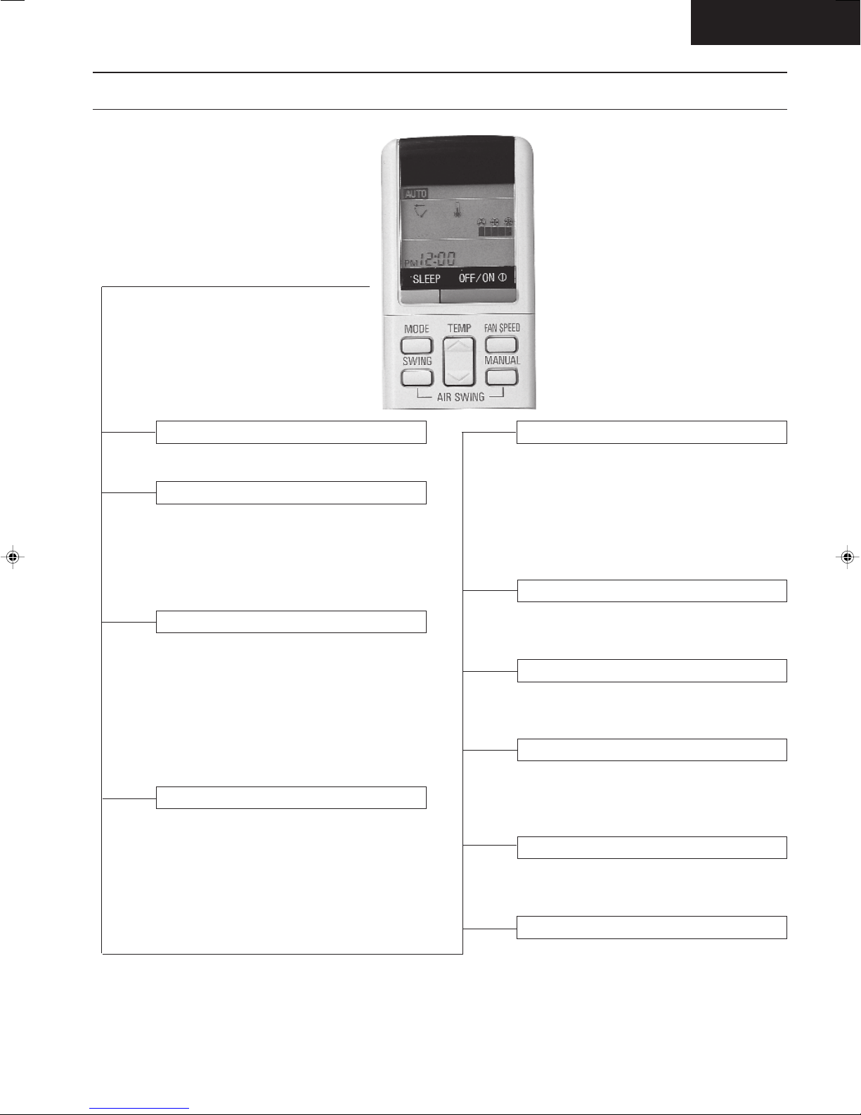
Remote Control
CS-MC90KE
OFF / ON I
MODE
FAN SPEED
AIR SWING
Operation OFF / ON
Operation Mode Selection
• AUTO Automatic Operation Mode
• COOL Cooling Operation Mode
• DRY Soft Dry Operation Mode
• FAN Air Circulation Mode
Indoor Fan Speed Selection
• h j k Low Speed
l
• h j k Medium Speed
lll
• h j k High Speed
lllll
• AUTOFAN Automatic Fan Speed
Airflow Direction Control
• SWING Automatic Airflow Direction
Control
• MANUAL Airflow Direction Manual Control
TEMP.
ON-TIMER
OFF-TIMER
TIME
SET
CANCEL
CLOCK
(q)
Room Temperature Setting
• Temperature Setting (16˚C to 30˚C)
• Automatic Operation
m / n 2˚C lower than standard
n Standard
n - o 2˚C higher than standard
Timer Operation Selection
• 24-hour, OFF / ON Real Timer Setting.
Time / Timer Setting
• Hours and minutes setting.
Timer Operation Set / Cancel
• ON Timer and OFF Timer setting and
cancellation.
Clock Setting
• Current time setting.
– 2 –
SLEEP
Sleep Mode Operation OFF / ON
CS-MC90KE
Functions
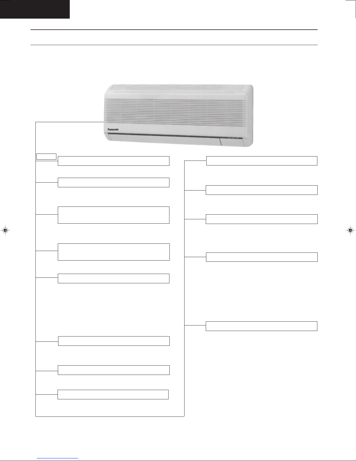
Indoor Unit
POWER I
AUTO
OFF / ON
TEST RUN
OFF / ON
Power Switch OFF / ON
Auto Operation Switch
• Used when the remote control cannot be
used.
Remote Control Signal Receiving
Sound Control
• It can be controlled by pressing Auto
Operation Switch for 10 seconds.
Operation Test Running / Pump
Down Switch
• Used when test running or servicing.
Operation Indication Lamps (LED)
• POWER (Red)...... Lights up in operation,
blinks in Automatic
Operation Mode judging
• SLEEP (Orange)..... Lights up in Sleep
Mode Operation
• TIMER (Orange)..... Lights up in Timer
Setting
Operation Mode
• Cooling, Soft Dry, Air Circulation and
Automatic Mode.
Auto Restart Control
• Operation is restarted after power failure
at previous setting mode.
Anti-Freezing Control
• Anti-Freezing control for indoor heat
exchanger. (Cooling and Soft Dry)
Sleep Mode Auto Control
• Indoor Fan operates and stops at 4-second
intervals at low speed.
• Operation stops after 8 hours.
Indoor Fan Speed Control
• High, Medium and Low.
• Automatic Fan Speed Mode
– Cooling : Fan rotates at Hi and Me
speed. Deodorizing control is
available.
– Soft Dry : Fan rotates at SLo and Lo
speed. Deodorizing control is
available.
Airflow Direction Control
• Automatic air swing and manual adjusted
by remote control for vertical airflow.
• Manually adjusted by hand for horizontal
airflow.
Time Delay Safety Control
• Restarting is inhibited for appro. 3 minutes.
7 Minutes Time Save Control
• Cooling Operation only.
– 3 –

Functions
Outdoor Unit
CS-MC90KE
Compressor Reverse Rotation
Protection Control
• To protect compressor from reverse rotation
when there is a instantaneous power failure.
60 secs. Forced Operation Control
• Once the compressor is activated, it does not
stop for 60 secs. (Stops immediately with
remote control stop signal.)
Overload Protector
Restart Control
(3 minutes)
• Once the compressor stops, the compressor
and the outdoor fan motor will not start for 3
minutes.
(Fan motor is still running if the compressor is
stopped by overload protector tripping.)
Starting Current Control
(2 seconds delay)
• When both compressors are started
simultaneously, one compressor will start
immediately whereas another compressor
will start after 2 seconds.
– 4 –
CS-MC90KE
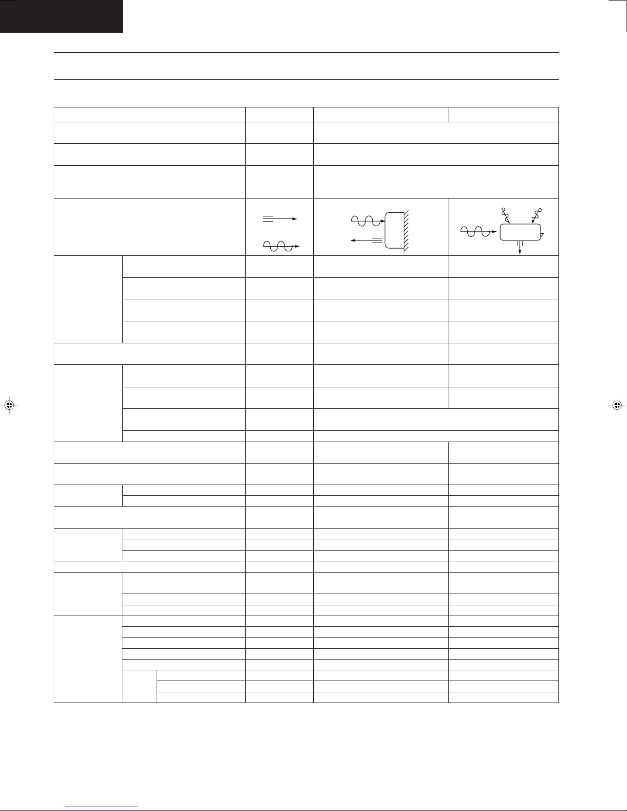
Product Specifications
Cooling Capacity
Moisture Removal
Power Source
Airflow Method
Air Volume
Noise Level
Electrical
Data
Piping Connection Port
(Flare piping)
Pipe Size
(Flare piping)
Drain
Hose
Power Cord Length
Dimensions
Net Weight
Compressor
Air Circulation
Indoor Air (Lo)
Indoor Air (Me)
Indoor Air (Hi)
Outdoor Air
Input
Running Current
COP
Starting Current
Inner diameter
Length
Number of core-wire
Motor Type
Rated Output
Motor Type
Fan Low
Speed Medium
Height
Width
Depth
Type
Type
Material
Input
Rated Output
High
Unit
kW
Btu/h
s/h
Pint/h
Phase
V
Cycle
OUTLET
INTAKE
3
/min (cfm)
m
3
m
/min (cfm)
3
m
/min (cfm)
m3/min (cfm)
dB (A)
W
A
W/W
A
inch
inch
inch
inch
mm
m
m
inch (mm)
inch (mm)
inch (mm)
lb (kg)
W
W
W
rpm
rpm
rpm
CS-MC90KE
(1 unit) 2.82 - 2.78
9,600 - 9,400
(1 unit) 1.6
3.4
Single
240 - 220
SIDE VIEW
7.2 (250)
7.4 (260)
7.5 (260)
–
High 36 - 35, Low 31 - 29
(1 unit) 30 - 25
(2 units) 30 × 2 - 25 × 2
(1 unit) 0.14 - 0.13
(2 units) 0.14 × 2 - 0.13 × 2
(1 unit) 2.5 - 2.5
21.5 - 19.5
G ; Half Union 3/8"
L ; Half Union 1/4"
G (gas side) ; 3/8"
L (liquid side) ; 1/4"
12
0.7
2.1
3 (1.0 mm2)
11-7/16 (290)
31-15/32 (799)
6-29/32 (175)
18 (8.0)
–
–
–
Cross-flow Fan
AS + Glass Fiber 30%
Induction (4-poles)
22
5
990
1,100
1,180
CU-MC140KE
(2 unit) 1.81
6,150 × 2 - 6,100 × 2
(2 unit) 1.05
2.2 × 2
50
TOP VIEW
(1 unit) 1,120 - 1,075
(2 units) 1,160 - 1,110
(1 unit) 4.96 - 4.97
(2 units) 5.12 - 5.14
(2 units) 3.1 - 3.2
G ; 3-way valve 3/8"
L ; 2-way valve 1/4"
G (gas side) ; 3/8"
L (liquid side) ; 1/4"
21-1/4 (540)
29-15/16 (760)
9-7/8 (250)
Rotary (1 cylinder)
rolling piston type
Induction (2-poles)
Propeller Fan
AES + Glass Fiber 16%
Induction (6-poles)
× 2 - 1.79 × 2
× 2
–
–
–
–
47 - 46
–
–
–
–
77 (35)
900
37
15
–
–
730
– 5 –

Product Specifications
CS-MC90KE
Unit
Heat
Exchanger
Refrigerant Control Device
Refrigeration Oil
Refrigerant (R-22)
Thermostat
Protection Device
Capillary Tube
Air Filter
Capacity Control
Compressor Capacitor
Fan Motor Capacitor
• Specifications are subject to change without notice for further improvement.
Description
Tube material
Fin material
Fin Type
Row / Stage
FPI
Size (W × H × L)
Length
Flow Rate
Inner Diameter
Material
Style
mm
(c.c)
g (oz)
mm
s/min
mm
µF, VAC
µF, VAC
CS-MC90KE
Evaporator
Copper
Aluminium
Slot Fin
(Plate fin configuration, forced draft)
2 × 12
17
600 × 252 × 25.4
–
–
–
Electronic Control
–
–
–
–
P.P.
Honeycomb
Capillary Tube
–
0.6 µF, 400 VAC
CU-MC140KE
Condenser
Copper
Aluminium
Corrugated Fin
1 × 20
19
687 × 508 × 22
Capillary Tube
SUNISO 4GDID or
ATMOS M60 (350)
850 (30.0)
–
Overload Protector
430
16.1
1.6
–
30 µF, 440 VAC
1.0 µF, 430 VAC
– 6 –

CS-MC90KE
Product Specifications
Cooling Capacity
Moisture Removal
Power Source
Airflow Method
Air Volume
Noise Level
Electrical
Data
Piping Connection Port
(Flare piping)
Pipe Size
(Flare piping)
Drain
Hose
Power Cord Length
Dimensions
Net Weight
Compressor
Air Circulation
Indoor Air (Lo)
Indoor Air (Me)
Indoor Air (Hi)
Outdoor Air
Input
Running Current
COP
Starting Current
Inner diameter
Length
Number of core-wire
Motor Type
Rated Output
Motor Type
Fan Low
Speed Medium
Height
Width
Depth
Type
Type
Material
Input
Rated Output
High
Unit
kW
Btu/h
s/h
Pint/h
Phase
V
Cycle
OUTLET
INTAKE
3
/min (cfm)
m
3
m
/min (cfm)
3
m
/min (cfm)
m3/min (cfm)
dB (A)
W
A
W/W
A
inch
inch
inch
inch
mm
m
m
inch (mm)
inch (mm)
inch (mm)
lb (kg)
W
W
W
rpm
rpm
rpm
CS-MC90KE
(1 unit) 2.44 - 2.40
8,300 - 8,100
(1 unit) 1.5
3.2
240 - 220
SIDE VIEW
7.2 (250)
7.4 (260)
7.5 (260)
–
High 36 - 35, Low 31 - 29
(1 unit)
770 - 730
(1 unit)
3.3 - 3.4
3.2 - 3.3
(1 unit) 16 - 15
G ; Half Union 3/8"
L ; Half Union 1/4"
G (gas side) ; 3/8"
L (liquid side) ; 1/4"
12
0.7
2.1
3 (1.0 mm2)
11-7/16 (290)
31-15/32 (799)
6-29/32 (175)
18 (8.0)
–
–
–
Cross-flow Fan
AS + Glass Fiber 30%
Induction (4-poles)
22
5
990
1,100
1,180
CU-MC180KE
(2 units)2.44 × 2 - 2.40 × 2
8,300 × 2 - 8,100 × 2
(2 units)1.3 × 2
2.75 × 2
Single
50
TOP VIEW
–
–
–
–
55 - 53
(2 units)
770 × 2 - 730 × 2
(2 units)
3.3 × 2 - 3.4 × 2
(2 units) 16 × 2 - 15 × 2
G ; 3-way valve 3/8"
L ; 2-way valve 1/4"
G (gas side) ; 3/8"
L (liquid side) ; 1/4"
–
–
–
–
25-21/32 (651)
35-3/16 (893)
13-19/32 (345)
132 (60)
Rotary (1 cylinder)
rolling piston type
Induction (2-poles)
650 × 2
Propeller Fan
AES + Glass Fiber 16%
Induction (6-poles)
108
50
–
–
730
– 7 –

Product Specifications
CS-MC90KE
Unit
Heat
Exchanger
Refrigerant Control Device
Refrigeration Oil
Refrigerant (R-22)
Thermostat
Protection Device
Capillary Tube
Air Filter
Capacity Control
Compressor Capacitor
Fan Motor Capacitor
• Specifications are subject to change without notice for further improvement.
Description
Tube material
Fin material
Fin Type
Row / Stage
FPI
Size (W × H × L)
Length
Flow Rate
Inner Diameter
Material
Style
mm
(c.c)
g (oz)
mm
s/min
mm
µF, VAC
µF, VAC
CS-MC90KE
Evaporator
Copper
Aluminium
Slot Fin
(Plate fin configuration, forced draft)
2 × 12
17
600 × 252 × 25.4
–
–
–
Electronic Control
–
–
–
–
P.P.
Honeycomb
Capillary Tube
–
0.6 µF, 400 VAC
CU-MC180KE
Condenser
Copper
Aluminium
Corrugated Fin
2 × 24
16
560 × 609.6 × 44
Capillary Tube
SUNISO 4GDID or
ATMOS M60 (270)
650 × 2 (22.9 × 2)
–
Overload Protector
1,170
10.0
1.6
–
25 µF, 370 VAC
3.0 µF, 450 VAC
– 8 –

CS-MC90KE
Product Specifications
Cooling Capacity Per Unit
Moisture Removal
Power Source
Airflow Method
Air Volume
Noise Level
Electrical
Data
Piping Connection Port
(Flare piping)
Pipe Size
(Flare piping)
Drain
Hose
Power Cord Length
Dimensions
Net Weight
Compressor
Air
Circulation
Indoor Air (Lo)
Indoor Air (Me)
Indoor Air (Hi)
Outdoor Air
Input
Running Current
COP
Starting Current
Inner diameter
Length
Number of core-wire
Height
Width
Depth
Type
Motor Type
Rated Output
Type
Material
Motor Type
Input
Rated Output
Fan Low
Speed Medium
High
Unit
kW
Btu/h
s/h
Pint/h
Phase
V
Cycle
OUTLET
INTAKE
m3/min (cfm)
3
/min (cfm)
m
m3/min (cfm)
m3/min (cfm)
dB (A)
kW
A
W/W
A
inch
inch
inch
inch
mm
m
m
inch (mm)
inch (mm)
inch (mm)
lb (kg)
W
W
W
rpm
rpm
rpm
CS-MC90KE
Single Operation
(A, B1, B2)
–
–
SIDE VIEW
7.2 (250)
7.4 (260)
7.5 (260)
–
High 36-35, Low 31-29
0.030-0.025
0.14-0.13
–
(A unit) 16-15
G ; Half Union 3/8"
L ; Half Union 1/4"
G (gas side) ; 3/8"
L (liquid side) ; 1/4"
12
0.7
2.1
2
3 (1.0 mm
11-7/16 (290)
31-15/32 (799)
6-29/32 (175)
18 (8.0)
Cross-flow Fan
AS + Glass Fiber 30%
Induction (4-poles)
1,100
1,180
)
–
–
–
22
5
990
CU-3MC200KE
Single Operation Double Operation Triple Operation
(A) (B1 or B2) (B1 + B2) (A +B1 or B2) (A + B1 + B2)
2.40-2.34 2.82-2.78 3.60-3.52 5.22-5.12 6.00-5.86
8,100-7,900 9,600-9,400 12,200-12,000 17,800-17,400 20,400-20,000
1.5 1.6 2.1-2.0 2.9-2.8 3.3-3.2
3.2 3.4 4.4-4.2 6.1-5.9 7.0-6.8
Single
240 - 220
50
TOP VIEW
–
–
–
–
56 - 54
0.79-0.75 1.09-1.05 1.15-1.10 1.79-1.70 1.83-1.77
3.36-3.47 4.76-4.77 4.92-5.04 7.62-7.74 7.78-8.01
2.9-3.0 2.5-2.6 3.0-3.1 2.8-2.9 3.1-3.2
(B unit) 22-21
G ; 3-way valve 3/8"
L ; 2-way valve 1/4"
G (gas side) ; 3/8"
L (liquid side) ; 1/4"
–
–
–
–
25-21/32 (651)
35-3/16 (893)
13-19/32 (345)
141 (64)
Rotary (1 cylinder)
rolling piston type
Induction (2-poles)
650 + 900
Propeller Fan
AES + Glass Fiber 16%
Induction (6-poles)
108
50
–
–
730
– 9 –

Product Specifications
CS-MC90KE
Unit
Heat
Exchanger
Refrigerant Control Device
Refrigeration Oil
Refrigerant (R-22)
Thermostat
Protection Device
Capillary Tube
Air Filter
Capacity Control
Compressor Capacitor
Fan Motor Capacitor
• Specifications are subject to change without notice for further improvement.
Description
Tube material
Fin material
Fin Type
Row / Stage
FPI
Size (W × H × L)
Length
Flow Rate
Inner Diameter
Material
Style
mm
(c.c)
g (oz)
mm
s/min
mm
µF, VAC
µF, VAC
CS-MC90KE
Evaporator
Copper
Aluminium
Slot Fin
(Plate fin configuration, forced draft)
2 × 12
17
600 × 252 × 25.4
–
–
–
Electronic Control
–
–
–
–
P.P.
Honeycomb
Capillary Tube
–
0.6 µF, 400 VAC
CU-3MC200KE
Condenser
Copper
Aluminium
Corrugated Fin
2 × 24
16
756.0 × 609.6 × 44
719.5
Capillary Tube
SUNISO 4GDID or
ATMOS M60
650 (23.0), 950 (33.5)
–
Overload Protector
935, 920, 1,170
20.0, 15.5, 10.0
2.0, 1.8, 1.6
–
25 µF, 440 VAC
3.0 µF, 450 VAC
– 10 –

CS-MC90KE
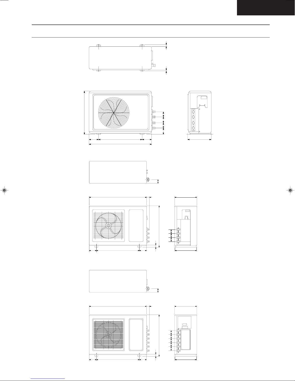
Dimensions
CS-MC90KE
Air intake
direction
<Front View>
790
175
Air outlet
direction
Left piping hole
290
55
<Back View>
60
Installation plate hooks
Drain ports
Gas
side
60
Liquid
side
290
Below
2100
52
48.5
115
(45)(410)
Right piping hole
Remote control transmitter
57
61
34.5
142
16
Relative position between the indoor unit and the installation plate <Front View>
(44)
Installation plate
Indoor unit external
dimensions line
7
276
7
(64)
Left piping hole
Centre notch
100 100
Arrow
Centre
710
457
350
Arrow
Installation plate positioning gauge
– 11 –
Slot (2 places)
Slot (2 places)
(45)
(115)
13.5
Right piping hole
Dimensions
CS-MC90KE
CU-MC140KE
CU-MC180KE
540
760
23
13
556555
90
115115 530
57
286
CU-3MC200KE
893
893
44
651
113113 664
32
57
44
651
345
656565
334
345
6565656565
113113 664
– 12 –
32
334
CS-MC90KE
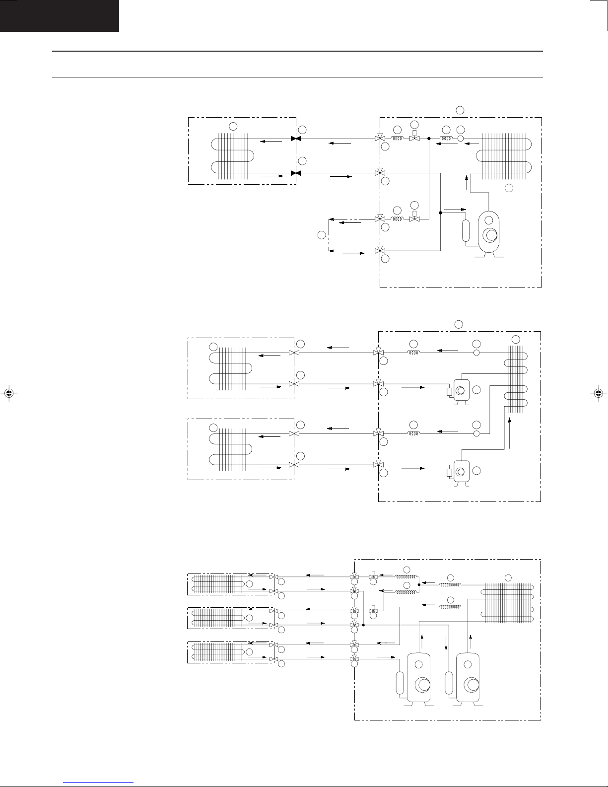
Refrigeration Cycle Diagram
CS-MC90KE / CU-MC140KE
1 Evaporator
2 Capillary tube (2)
3 3 way valve (1/4")
4 3 way valve (3/8")
5 Half union (1/4")
6 Half union (3/8")
7 Switching solenoid valve (A)
8 Switching solenoid valve (B)
9 Capillary tube (1)
! Condensor
" Compressor
# Outdoor unit
$ Strainer
% To indoor unit B
CS-MC90KE / CU-MC180KE
1 Evaporator
2 Capillary tube (2)
3 3 way valve (1/4")
4 3 way valve (3/8")
5 Half union (1/4")
6 Half union (3/8")
! Condensor
" Compressor
# Outdoor unit
$ Strainer
1
1
1
Indoor Unit A
Indoor Unit A
Indoor Unit B
5
6
Indoor Unit B
5
6
5
6
LIQUID SIDE
GAS SIDE
LIQUID SIDE
14
GAS SIDE
LIQUID SIDE
GAS SIDE
LIQUID SIDE
GAS SIDE
12
7
2
3
4
8
2
3
4
2
3
4
2
3
4
913
12
11
13
Comp.A
11
13
Comp.B
11
10
10
CS-MC90KE / CU-3MC200KE
1 Compressor (1)
2 Compressor (2)
3 Condensor
4 Capillary tube (1)
5 Capillary tube (2)
6 Capillary tube (3)
7 Switching solenoid valve
8 3 way valve (1/4")
9 3 way valve (3/8")
! Half union (1/4")
" Half union (3/8")
# Evaporator
INDOOR UNIT (B2)
INDOOR UNIT (B1)
12
12
INDOOR UNIT (A)
12
10
11
10
11
10
11
– 13 –
LIQUID SIDE
GAS SIDE
LIQUID SIDE
GAS SIDE
LIQUID SIDE
GAS SIDE
OUTDOOR UNIT
5
8
7
9
7
8
9
8
9
5
12
4
6
3
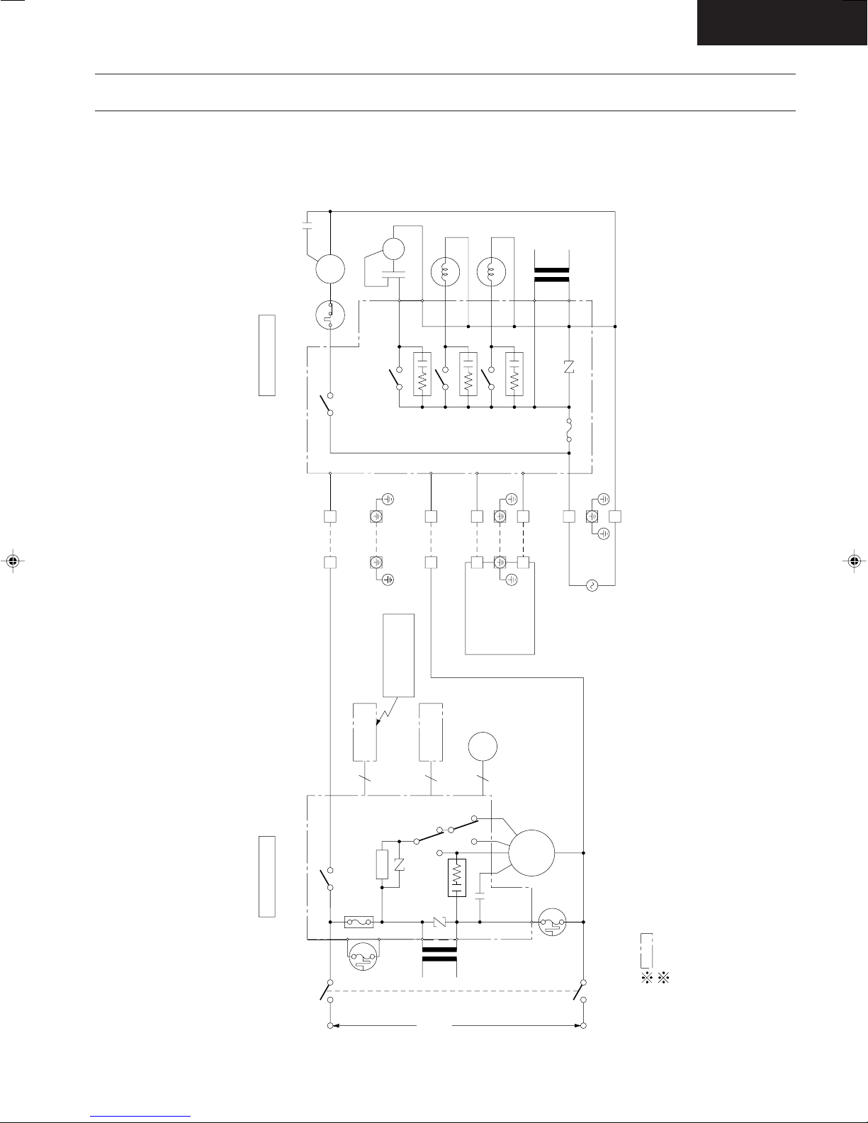
Block Diagram
22
11
3C
"C"
FUSE
3.15A
RY-C
RECEIVER
P.C.B.
SINGLE PHASE
220-240V ~
50Hz
RY-H
TRANS-
FORMER
THERMAL
FUSE
(99°C)
(102°C)
FUSE
THERMAL
ZNR1
FAN
MOTOR
POWER SWITCH
ELECTRONIC CONTROLLER
Indicates the electronic control unit.
Indicates the number of core wires. (Example:6C=6 core wires).
9740312
RY-M
P.C.B.
INDICATOR
4C
5C
STEPPING
MOTOR
INDOOR UNIT OUTDOOR UNIT
WIRELESS
REMOTE CONTROL
TRANSMITTER
ZNR2
SSR
MAIN
CS-MC90KE/CU-MC140KE
A-006C.DWG
CR1
INDOOR UNIT A
COMP
22
11
OLP
INDOOR UNIT B
SAME AS
UNIT A
C-COMP
RY-C
FUSE
3.15A
RY-FM
FAN
MOTOR
RY-VA2
VA2
CR1
VA1
RY-VA1
CR3
CR2
TRANS-
FORMER
ZNR1
L
N
POWER SUPPLY
OUTDOOR
220-240V ~
50Hz
C-FM
CS-MC90KE / CU-MC140KE
CS-MC90KE
– 14 –
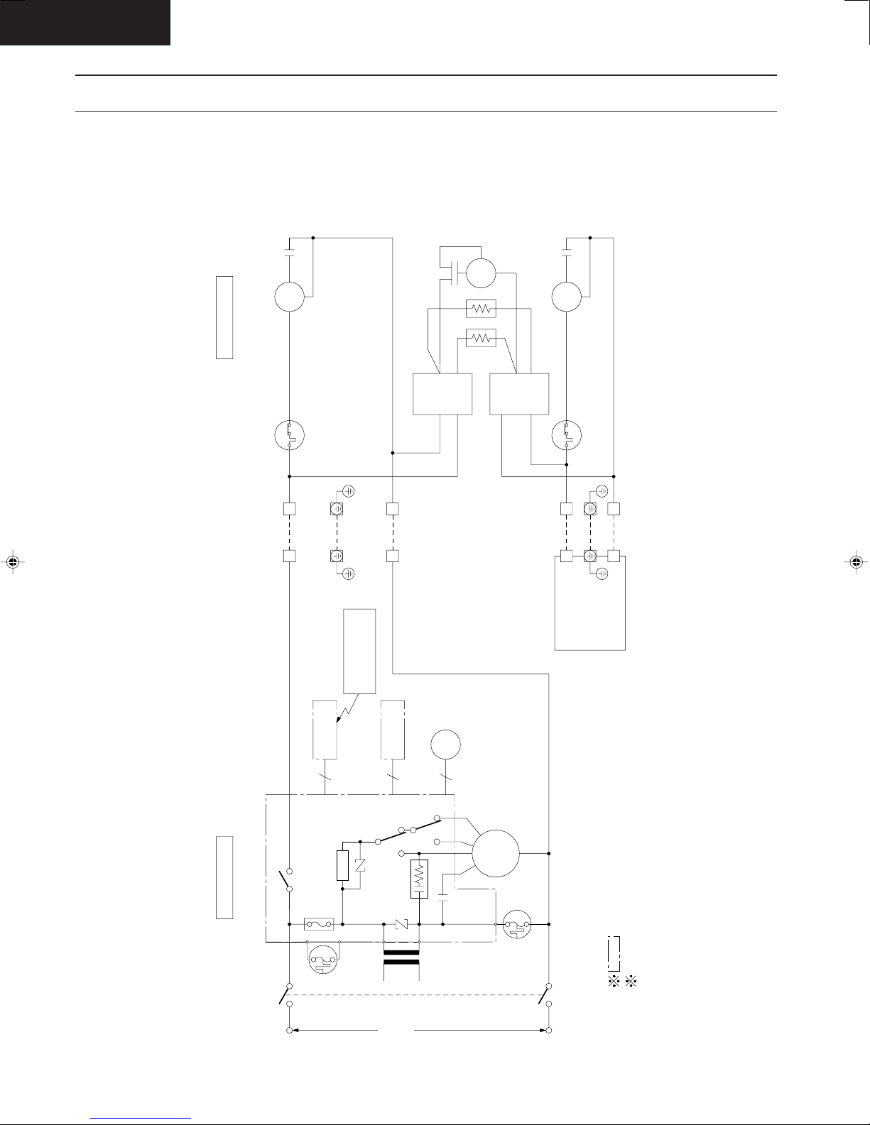
CS-MC90KE
22
11
3C
"C"
FUSE
3.15A
RY-C
RECEIVER
P.C.B.
SINGLE PHASE
220-240V ~
50Hz
RY-H
TRANS-
FORMER
THERMAL
FUSE
(99°C)
(102°C)
FUSE
THERMAL
ZNR1
FAN
MOTOR
POWER SWITCH
ELECTRONIC CONTROLLER
Indicates the electronic control unit.
Indicates the number of core wires. (Example:6C=6 core wires).
9740312
RY-M
P.C.B.
INDICATOR
4C
5C
STEPPING
MOTOR
INDOOR UNIT OUTDOOR UNIT
WIRELESS
REMOTE CONTROL
TRANSMITTER
ZNR2
SSR
MAIN
CS-MC90KE/CU-MC140KE
A-006.DWG
CR1
INDOOR UNIT A
COMPRESSOR
A
RELAY
RELAY
FAN
MOTOR
22
11
COMPRESSOR
B
OLP
OLP
INDOOR UNIT B
SAME AS
UNIT A
C-COMP
C-COMP
C-FM
Block Diagram
CS-MC90KE / CU-MC180KE
– 15 –
 Loading...