

Panasonic CS-MA90KE, CS-MA120KE, CU-MA180KE, CU-MA240KE, CS-MA70KE Service Manual
...
ORDER NO. MAC9611042C2
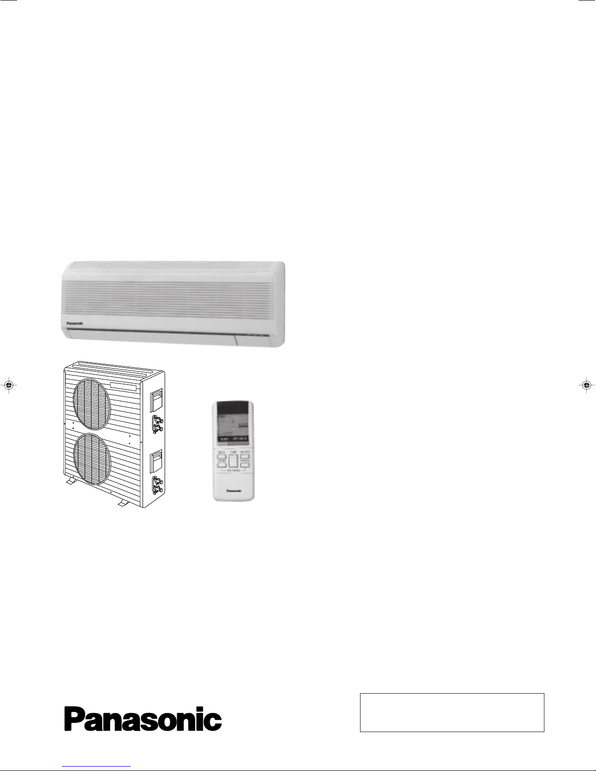
Service Manual
Multi-Split Air Conditioners
CS-MA90KE / CU-MA180KE
CS-MA120KE / CU-MA240KE
CS-MA70KE / CU-MA190KE
CS-MA120KE
Contents
● Features ..........................................................1
● Functions ...................................................2 – 4
● Product Specifications .............................5 – 10
● Dimensions ............................................11 – 12
● Refrigeration Cycle Diagram .........................13
● Block Diagram ...............................................14
● Wiring Diagram ......................................15 – 16
● Operation Details ...................................17 – 27
● Installation Information ..........................28 – 29
● 2-way, 3-way Valves..............................30 – 36
● Servicing Information ............................. 37 – 40
● Troubleshooting Guide ..........................41 – 42
● Technical Data.......................................43 – 46
● Exploded View .............................47, 49, 51, 53
● Replacement Parts List ...............48, 50, 52, 54
● Electronic Parts List .......................................55
1996 Matsushita Industrial Corp. Sdn. Bhd.
(11969-T)
All rights reserved. Unauthorized copying and distribution is a violation of law.

CS-A90KECS-MA90KE
!
WARNING
This service information is designed for experienced repair technicians only and is not designed for use by the general public. It does not contain
warnings or cautions to advise non-technical individuals of potential dangers in attempting to service a product. Products powered by electricity
should be serviced or repaired only by experienced professional technicians. Any attempt to service or repair the product or products dealt with
in this service information by anyone else could result in serious injury or death.
!
PRECAUTION OF LOW TEMPERATURE
In order to avoid frostbite, be assured of no refrigerant leakage during the installation or repairing of refrigeration circuit.
Features
• High Efficiency
• Compact Design
• Comfort Improvement
– Wider range of horizontal discharge air
– Longer hours of sleep mode operation
• Auto Restart
– Auto restart operation after power failure
• Removable and Washable
Front Panel
• Installation Work Improvement
– Long piping up to 15 m
• Quality Improvement
– Low voltage protection
– Gas leakage protection
– Prevent compressor reverse cycle
– 2-stage OLP to protect compressor
(CS-MA90KE / CS-MA120KE)
• Service Improvement
– Easy fan motor replacement procedure
– 1 –
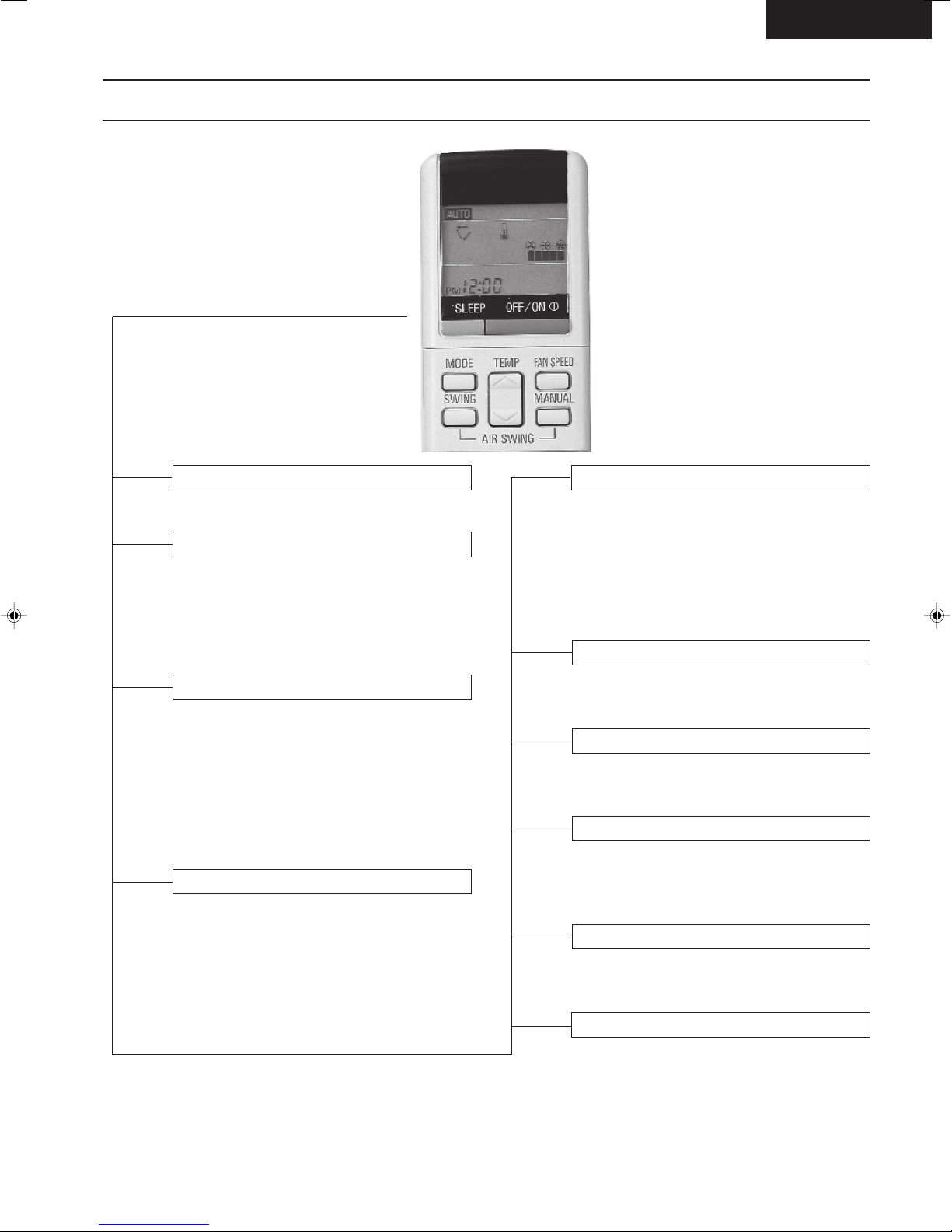
Functions
Remote Control
CS-MA90KE
OFF / ON L
MODE
FAN SPEED
SWING /
MANUAL
Operation OFF / ON
Operation Mode Selection
• AUTO Automatic Operation Mode
• HEAT Heating Operation Mode
• COOL Cooling Operation Mode
• DRY Soft Dry Operation Mode
Indoor Fan Speed Selection
• h j k Low Speed
l
• h j k Medium Speed
lll
• h j k High Speed
lllll
• AUTOFAN Automatic Fan Speed
Airflow Direction Control
• SWING Automatic Airflow Direction
Control
• MANUAL Airflow Direction Manual Control
TEMP.
ON-TIMER
OFF-TIMER
TIME
SET
CANCEL
CLOCK
(q)
Room Temperature Setting
• Temperature Setting (16˚C to 30˚C)
• Automatic Operation
m / n 2˚C lower than standard
n Standard
n - o 2˚C higher than standard
Timer Operation Selection
• 24-hour, OFF / ON Real Timer Setting.
Time / Timer Setting
• Hours and minutes setting.
Timer Operation Set / Cancel
• ON Timer and OFF Timer setting and
cancellation.
Clock Setting
• Current time setting.
– 2 –
SLEEP
Sleep Mode Operation OFF / ON
CS-A90KECS-MA90KE
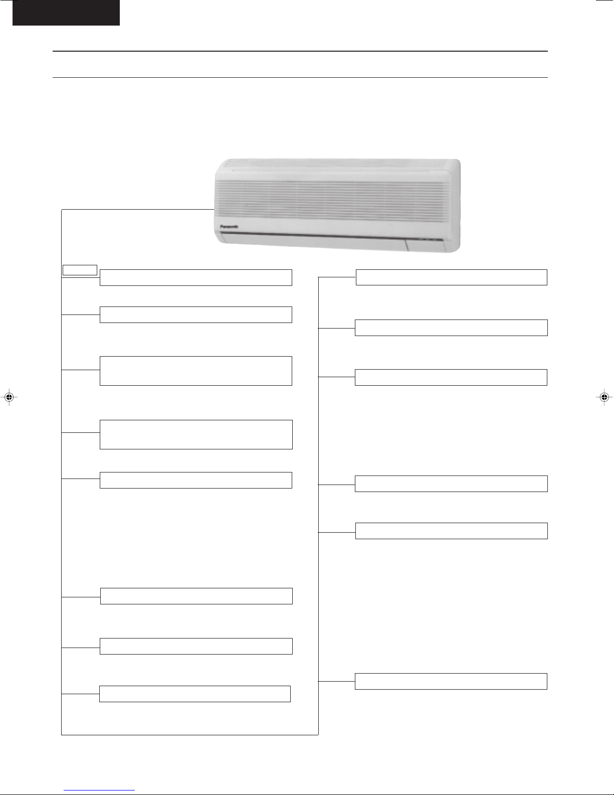
Functions
Indoor Unit
POWER L
AUTO
OFF / ON
TEST RUN
OFF / ON
Power Switch OFF / ON
Auto Operation Switch
• Used when the remote control cannot be
used.
Remote Control Signal Receiving
Sound Control
• It can be controlled by pressing Auto
Operation Switch for 10 seconds.
Operation Test Running / Pump
Down Switch
• Used when test running or servicing.
Operation Indication Lamps (LED)
• POWER (Red)...... Lights up in operation,
blinks in Automatic
Operation Mode judging
and Hot Start operation
• SLEEP (Orange)..... Lights up in Sleep
Mode Operation
• TIMER (Orange)..... Lights up in Timer
Setting
Operation Mode
• Heating, Cooling, Soft Dry and Automatic
Mode.
Time Delay Safety Control
• Restarting is inhibited for appro. 3 or 4
minutes.
7 Minutes Time Save Control
• Cooling Operation only.
Auto Restart Control
• Operation is restarted after power failure
at previous setting mode.
Anti-Freezing Control
• Anti-Freezing control for indoor heat
exchanger. (Cooling and Soft Dry)
Hot-Start Control
• The indoor fan stops until the indoor heat
exchanger temperature over 30°C.
• The indoor fan operates at SLo and Lo
when indoor heat exchanger temperature
reaches 30°C ~ 41°C.
• Hot Start is completed when indoor heat
exchanger reaches 41°C.
–
Sleep Mode Auto Control
• The operation starts at SLo speed and
stops after 8 hours.
Indoor Fan Speed Control
• High, Medium and Low.
• Automatic Fan Speed Mode
– Heating : Fan speed varies from Me
→ SLo in accordance with
indoor heat exchanger.
– Cooling : Fan rotates at Hi and Me
speed. Deodorizing control is
available.
– Soft Dry : Fan rotates at SLo speed.
Deodorizing control is
available.
Airflow Direction Control
• Automatic air swing and manual adjusted
by remote control for vertical airflow.
• Manually adjusted by hand for horizontal
airflow.
– 3 –
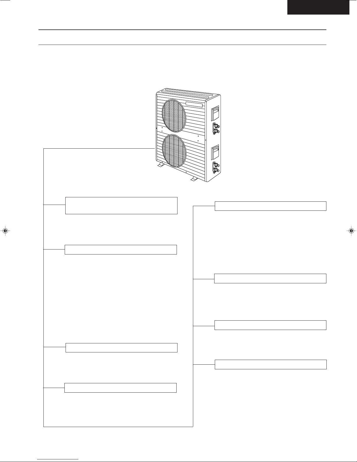
Functions
Outdoor Unit
CS-MA90KE
Compressor Reverse Rotation
Protection Control
• To protect compressor from reverse
rotation when there is a instantaneous
power failure.
Overload Protector
• CS-MA90KE and CS-MA120KE
2-stage OLP to protect the compressor.
Overload Protector will trip when
– Temperature of compressor increases to
120°C.
– High temperature or high current flow to
compressor.
(Refer circuit diagram for OLP characteristic)
• CS-MA70KE
OLP to protect the compressor.
– OLP characteristic can be referred to
circuit diagram.
60 Secs. Forced Operation Control
• Once the compressor is activated, it does
not stop for 60 secs. (Stops immediate
with remote control stop signal.)
Overload Protection Control
• Outdoor fan stops when indoor heat
exchanger temperature rises to 51°C and
restarts when the indoor heat exchanger
temperature drops to 49°C.
• Compressor stops when indoor heat
exchanger temperature reaches 65°C or
above.
(Heating Operation only)
Compressor Protection Control
• If the outdoor fan motor is not running after
compressor starts for 50 secs., compressor
will stop. (Cooling and Soft Dry Operation
only).
4-Way Valve Control
• When the unit is switched to “OFF” during
Heating Operation, 4-way valve stays at
Heating position for 5 minutes.
Outdoor Fan Operation Control
• Inner protector.
Deice Control
•
To prevent frosting at outdoor heat
exchanger. (Only for Heating Operation)
• Outdoor indoor heat exchanger is sensed
by TRS (Thermal Reed Switch).
– 4 –
CS-A90KECS-MA90KE
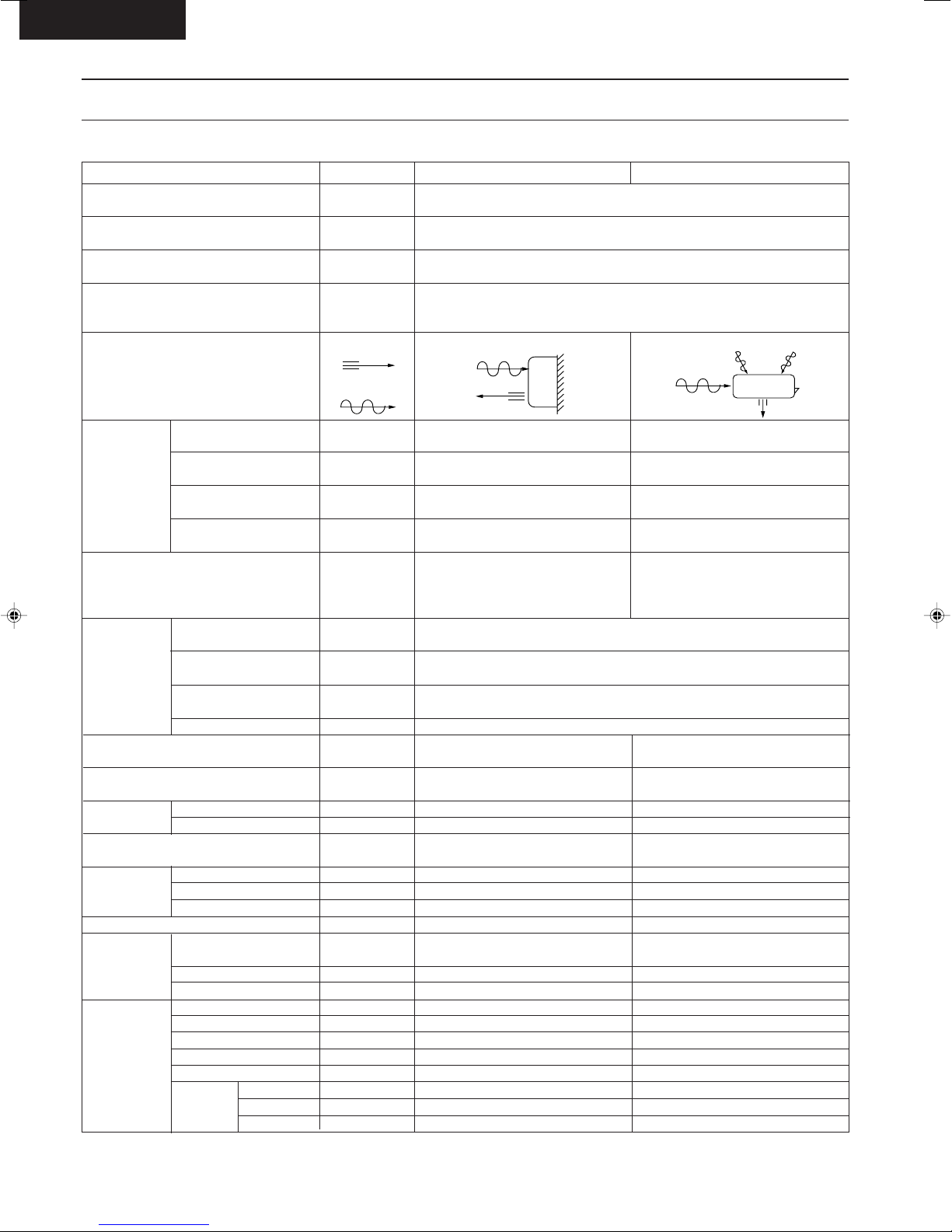
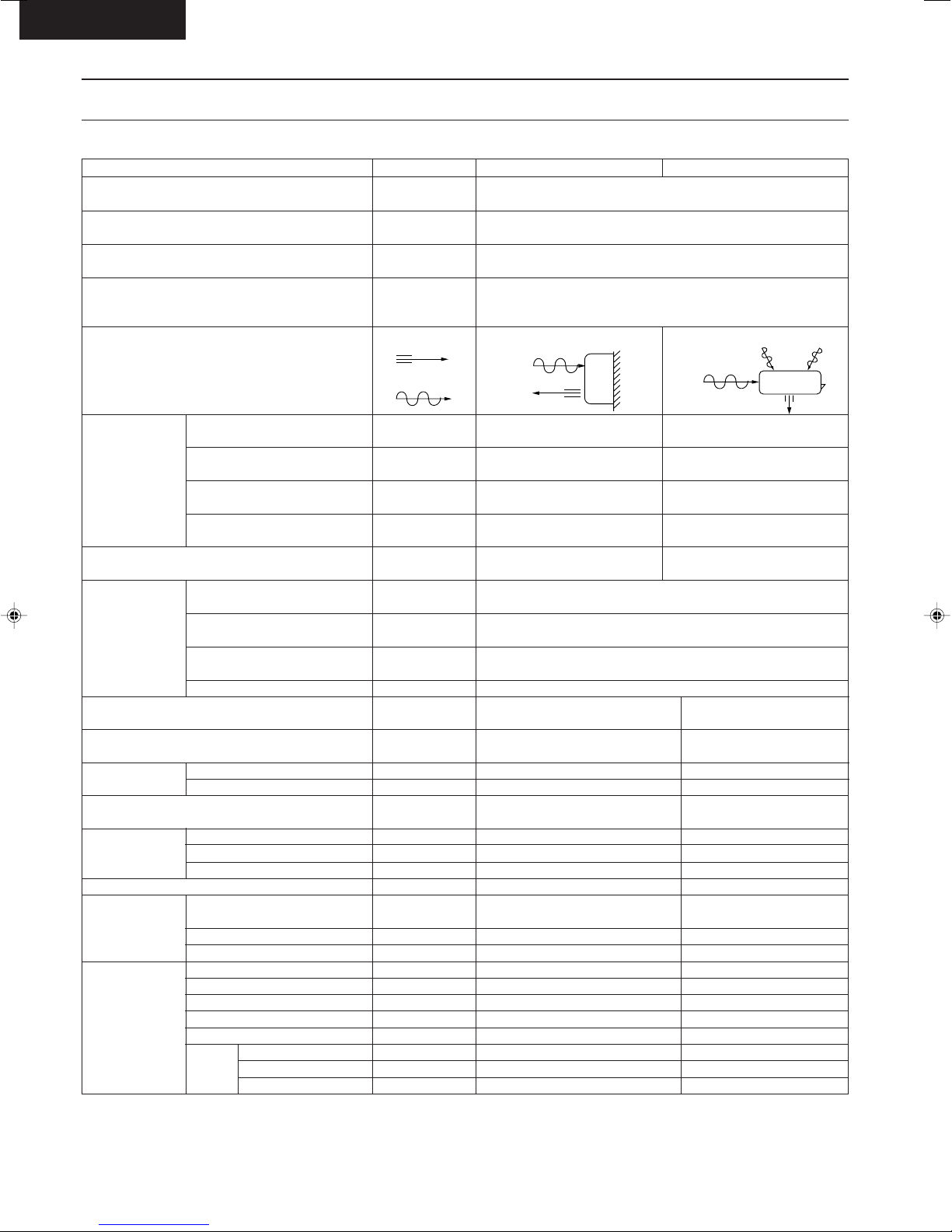
Product Specifications
Cooling Capacity
Heating Capacity
Moisture Removal
Power Source
Airflow Method
Air Volume
Noise Level
Electrical
Data
Piping Connection Port
(Flare piping)
Pipe Size
(Flare piping)
Drain
Hose
Power Cord Length
Dimensions
Net Weight
Compressor
Air Circulation
Indoor Air (Lo)
Indoor Air (Me)
Indoor Air (Hi)
Outdoor Air
Input
Running Current
COP
Starting Current
Inner diameter
Length
Number of core-wire
Motor Type
Rated Output
Motor Type
Fan Low
Speed Medium
Height
Width
Depth
Type
Type
Material
Input
Rated Output
High
Unit
kW
Btu/h
kW
Btu/h
s/h
Pint/h
Phase
V
Cycle
OUTLET
INTAKE
m3/min (cfm)
3
m
/min (cfm)
3
/min (cfm)
m
3
/min (cfm)
m
dB (A)
W
A
W/W
A
inch
inch
inch
inch
mm
m
m
inch (mm)
inch (mm)
inch (mm)
lb (kg)
W
W
W
rpm
rpm
rpm
CS-MA70KE, CS-MA120KE
2.05 - 2.00, 3.50 - 3.45
7,000 - 6,800, 11,900 - 11,800
2.15 - 2.10, 4.10 - 4.00
7,300 - 7,200, 14,000 - 13,600
SIDE VIEW
Cooling ; 5.5 (190), 7.5 (260)
Heating ; 5.5 (190), 7.8 (280)
Cooling ; 6.0 (210), 8.4 (300)
Heating ; 6.0 (210), 8.7 (310)
Cooling ; 6.7 (240), 9.3 (330)
Heating ; 6.7 (240), 9.7 (340)
–
Cooling ; High 36-35, 42-41,
Low 30-29, 38-37
Heating ; High 36-35, 43-42,
Low 30-29, 38-37
Cooling ; 660 - 600, 1,250 - 1,220
Heating ; 640 - 600, 1,280 - 1,230
Cooling ; 3.2 - 3.0, 5.6 - 5.7
Heating ; 3.1 - 3.0, 5.7 - 5.7
Cooling ; 3.1 - 3.3, 2.8 - 2.8
Heating ; 3.4 - 3.5, 3.2 - 3.3
G ; Half Union 3/8", 1/2"
L ; Half Union 1/4", 1/4"
G (gas side) ; 3/8", 1/2"
L (liquid side) ; 1/4", 1/4"
12
0.7
2.1
20
2
)
–
–
–
–
3 (1.0 mm
11-7/16 (290)
31-15/32 (799)
6-29/32 (175)
18 (8.0)
Cross-flow Fan
AS + Glass Fiber 30%
Transistor (4-poles)
950, 1,210
1,030, 1,350
1,150, 1,500
CU-MA190KE
1.3, 2.0
2.7, 4.2
Single
240 - 220
50
TOP VIEW
–
–
–
22.4 (790), 22.0 (780)
Cooling ; High 47-45, 49-48 (51-50)
Heating ; High 49-47, 49-48 (52-51)
13, 25
G ; 3-way valve 3/8", 1/2"
L ; 2-way valve 1/4", 1/4"
G (gas side) ; 3/8", 1/2"
L (liquid side) ; 1/4", 1/4"
–
–
–
–
39- 31/32(1015)
30-23/32 (780)
9-21/32 (245)
159 (72)
Rotary (1 cylinder)
rolling piston type
Induction (2-poles)
550, 1,100
Propeller Fan
AES + Glass Fiber 12%
Induction (6-poles)
58.6 × 2
20 × 2
–
–
730
– 5 –
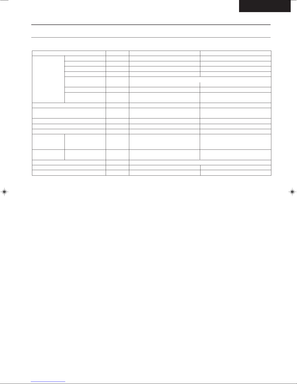
Product Specifications
CS-MA90KE
Unit
Heat
Exchanger
Refrigerant Control Device
Refrigeration Oil
Refrigerant (R-22)
Thermostat
Protection Device
Capillary Tube
Air Filter
Capacity Control
Compressor Capacitor
Fan Motor Capacitor
• Specifications are subject to change without notice for further improvement.
Description
Tube material
Fin material
Fin Type
Row / Stage
FPI
Size (W × H × L)
Length
Flow Rate
Inner Diameter
Material
Style
mm
(c.c)
g (oz)
mm
s/min
mm
µF, VAC
µF, VAC
CS-MA70KE, CS-MA120KE
Evaporator
Copper
Aluminium
Slot Fin
(Plate fin configuration, forced draft)
2 × 12 2 × 12
18 21
600 × 252 × 25.4
–
–
–
Electronic Control
–
–
–
–
P.P.
Honeycomb
–
–
CU-MA190KE
Condenser
Copper
Aluminium
Corrugated Fin
1 × 18 2 × 19
19 16
856 × 457.2 × 22 706.2 × 482.6 × 44
669.9
Capillary Tube
SUNISO 4GDID or
ATMOS M60 (290, 430)
860, 1,100 (30.4, 38.8)
–
Overload Protector
Cooling ; 920, 720, Heating ; 590, 550
Cooling ; 4.0, 7.5, Heating ; 8.2, 12.5
Cooling ; 1.1, 1.3, Heating ; 1.3, 1.5
–
Capillary Tube
15 µF, 440VAC 30 µF, 370VAC
1.2 µF, 400VAC 1.2 µF, 400VAC
– 6 –
CS-A90KECS-MA90KE
Product Specifications
Cooling Capacity
Heating Capacity
Moisture Removal
Power Source
Airflow Method
Air Volume
Noise Level
Electrical
Data
Piping Connection Port
(Flare piping)
Pipe Size
(Flare piping)
Drain
Hose
Power Cord Length
Dimensions
Net Weight
Compressor
Air Circulation
Indoor Air (Lo)
Indoor Air (Me)
Indoor Air (Hi)
Outdoor Air
Input
Running Current
COP
Starting Current
Inner diameter
Length
Number of core-wire
Motor Type
Rated Output
Motor Type
Fan Low
Speed Medium
Height
Width
Depth
Type
Type
Material
Input
Rated Output
High
Unit
kW
Btu/h
kW
Btu/h
s/h
Pint/h
Phase
V
Cycle
OUTLET
INTAKE
3
/min (cfm)
m
3
/min (cfm)
m
m3/min (cfm)
m3/min (cfm)
dB (A)
W
A
W/W
A
inch
inch
inch
inch
mm
m
m
inch (mm)
inch (mm)
inch (mm)
lb (kg)
W
W
W
rpm
rpm
rpm
CS-MA90KE
2.65 × 2 - 2.60 × 2
9,000 × 2 - 8,900 × 2
3.15 × 2 - 3.00 × 2
10,700 × 2 - 10,200 × 2
1.6 × 2
3.4 × 2
Single
240 - 220
50
SIDE VIEW
Cooling ; 6.3 (220)
Heating ; 6.4 (230)
Cooling ; 7.4 (260)
Heating ; 7.5 (260)
Cooling ; 8.4 (300)
Heating ; 8.6 (300)
–
Cooling ; High 38-38, Low 30-30
Heating ; High 39-39, Low 30-30
Cooling ; 940 × 2 - 890 × 2
Heating ; 950 × 2 - 880 × 2
Cooling ; 4.1 × 2 - 4.1 × 2
Heating ; 4.2 × 2 - 4.1 × 2
Cooling ; 2.8 - 2.9
Heating ; 3.3 - 3.4
20 × 2
G ; Half Union 3/8"
L ; Half Union 1/4"
G (gas side) ; 3/8"
L (liquid side) ; 1/4"
12
0.7
2.1
18 (8.0)
–
–
–
–
20
980
1,150
1,310
2
)
3 (1.0mm
11-7/16 (290)
31-15/32 (799)
6-29/32 (175)
Cross-flow Fan
AS + Glass Fiber 30%
Transistor (4-poles)
CU-MA180KE
TOP VIEW
–
–
–
22.4 (790)
Cooling ; High 49-48 (52-51)
Heating ; High 49-47 (52-50)
G ; 3-way valve 3/8"
L ; 2-way valve 1/4"
G (gas side) ; 3/8"
L (liquid side) ; 1/4"
–
–
–
–
38-3/4 (985)
30-23/32 (780)
9-21/32 (245)
152 (69)
Rotary (1 cylinder)
rolling piston type
Induction (2-poles)
750 × 2
Propeller Fan
AES + Glass Fiber 12%
Induction (6-poles)
58.6 × 2
20 × 2
–
–
730
– 7 –

Product Specifications
CS-MA90KE
Unit
Heat
Exchanger
Refrigerant Control Device
Refrigeration Oil
Refrigeration (R-22)
Thermostat
Protection Device
Capillary Tube
Air Filter
Capacity Control
Compressor Capacitor
Fan Motor Capacitor
• Specifications are subject to change without notice for further improvement.
Description
Tube material
Fin material
Fin Type
Row / Stage
FPI
Size (W × H × L)
Length
Flow Rate
Inner Diameter
Material
Style
mm
(c.c)
g (oz)
mm
s/min
mm
µF, VAC
µF, VAC
CS-MA90KE
Evaporator
Copper
Aluminium
Slot Fin
(Plate fin configuration, forced draft)
2 × 12
18
600 × 252 × 25.4
–
–
–
Electronic Control
–
–
–
–
P.P.
Honeycomb
Capillary Tube
–
–
Cooling ; 1,033, Heating ; 585
Cooling ; 4.8, Heating ; 9.9
Cooling ; 1.2, Heating ; 1.4
(Upper unit) 1.0 µF, 400VAC
(Lower unit) 1.2 µF, 400VAC
CU-MA180KE
Condenser
Copper
Aluminium
Corrugated Fin
1 × 18
19
856 × 457.2 × 22
Capillary Tube
SUNISO 4GDID or
ATMOS M60 (350 × 2)
850 × 2 (30.0 × 2)
–
Overload Protector
–
–
25 µF, 370VAC
– 8 –

CS-A90KECS-MA90KE
Product Specifications
Cooling Capacity
Heating Capacity
Moisture Removal
Power Source
Airflow Method
Air Volume
Noise Level
Electrical
Data
Piping Connection Port
(Flare piping)
Pipe Size
(Flare piping)
Drain
Hose
Power Cord Length
Dimensions
Net Weight
Compressor
Air Circulation
Indoor Air (Lo)
Indoor Air (Me)
Indoor Air (Hi)
Outdoor Air
Input
Running Current
COP
Starting Current
Inner diameter
Length
Number of core-wire
Motor Type
Rated Output
Motor Type
Fan Low
Speed Medium
Height
Width
Depth
Type
Type
Material
Input
Rated Output
High
Unit
kW
Btu/h
kW
Btu/h
s/h
Pint/h
Phase
V
Cycle
OUTLET
INTAKE
3
/min (cfm)
m
3
/min (cfm)
m
m3/min (cfm)
m3/min (cfm)
dB (A)
kW
A
W/W
A
inch
inch
inch
inch
mm
m
m
inch (mm)
inch (mm)
inch (mm)
lb (kg)
W
W
W
rpm
rpm
rpm
CS-MA120KE
3.50 × 2 - 3.45 × 2
11,900 × 2 - 11,800 × 2
4.10 × 2 - 4.00 × 2
14,000 × 2 - 13,600 × 2
2.0 × 2
4.2 × 2
Single
240 - 220
50
SIDE VIEW
Cooling ; 7.5 (260)
Heating ; 7.8 (280)
Cooling ; 8.4 (300)
Heating ; 8.7 (310)
Cooling ; 9.3 (330)
Heating ; 9.7 (340)
–
Cooling ; High 42-41, Low 38-37
Heating ; High 43-42, Low 38-37
Cooling ; 1.25 × 2 - 1.22 × 2
Heating ; 1.28 × 2 - 1.23 × 2
Cooling ; 5.6 × 2 - 5.7 × 2
Heating ; 5.7 × 2 - 5.7 × 2
Cooling ; 2.8 - 2.8
Heating ; 3.2 - 3.3
25 × 2
G ; Half Union 1/2"
L ; Half Union 1/4"
G (gas side) ; 1/2"
L (liquid side) ; 1/4"
12
0.7
2.1
2
3 (1.0mm
11-7/16 (290)
31-15/32 (799)
6-29/32 (175)
18 (8.0)
Cross-flow Fan
AS + Glass Fiber 30%
Induction (4-poles)
)
–
–
–
–
20
1,210
1,350
1,500
CU-MA240KE
TOP VIEW
–
–
–
22.0 (780)
Cooling ; High 49-48 (52-51)
Heating ; High 49-48(52-51)
G ; 3-way valve 1/2"
L ; 2-way valve 1/4"
G (gas side) ; 1/2"
L (liquid side) ; 1/4"
–
–
–
–
41-5/32 (1045)
30-23/32 (780)
9-21/32 (245)
183 (83)
Rotary (1 cylinder)
rolling piston type
Induction (2-poles)
1,100 × 2
Propeller Fan
AES + Glass Fiber 12%
Induction (6-poles)
58.6 × 2
20 × 2
–
–
730
– 9 –

Product Specifications
CS-MA90KE
Unit
Heat
Exchanger
Refrigerant Control Device
Refrigeration Oil
Refrigeration (R-22)
Thermostat
Protection Device
Capillary Tube
Air Filter
Capacity Control
Compressor Capacitor
Fan Motor Capacitor
• Specifications are subject to change without notice for further improvement.
Description
Tube material
Fin material
Fin Type
Row / Stage
FPI
Size (W × H × L)
Length
Flow Rate
Inner Diameter
Material
Style
mm
(c.c)
g (oz)
mm
s/min
mm
µF, VAC
µF, VAC
CS-MA120KE
Evaporator
Copper
Aluminium
Slot Fin
(Plate fin configuration, forced draft)
2 × 12
21
600 × 252 × 25.4
–
–
–
Electronic Control
–
–
–
–
P.P.
Honeycomb
Capillary Tube
–
–
Cooling ; 720, Heating ; 550
Cooling ; 7.5, Heating ; 12.5
Cooling ; 1.3, Heating ; 1.5
(Upper unit) 1.0 µF, 400VAC
(Lower unit) 1.2 µF, 400VAC
CU-MA240KE
Condenser
Copper
Aluminium
Corrugated Fin
2 × 19
16
706.2 × 482.6 × 44
669.9
Capillary Tube
SUNISO 4GDID or
ATMOS M60 (430 × 2)
1,100 × 2 (38.8 × 2)
–
Overload Protector
–
–
30 µF, 370VAC
– 10 –
CS-A90KECS-MA90KE
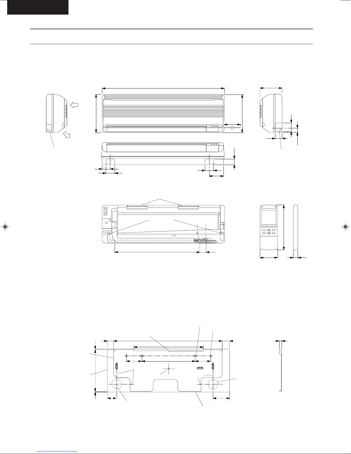
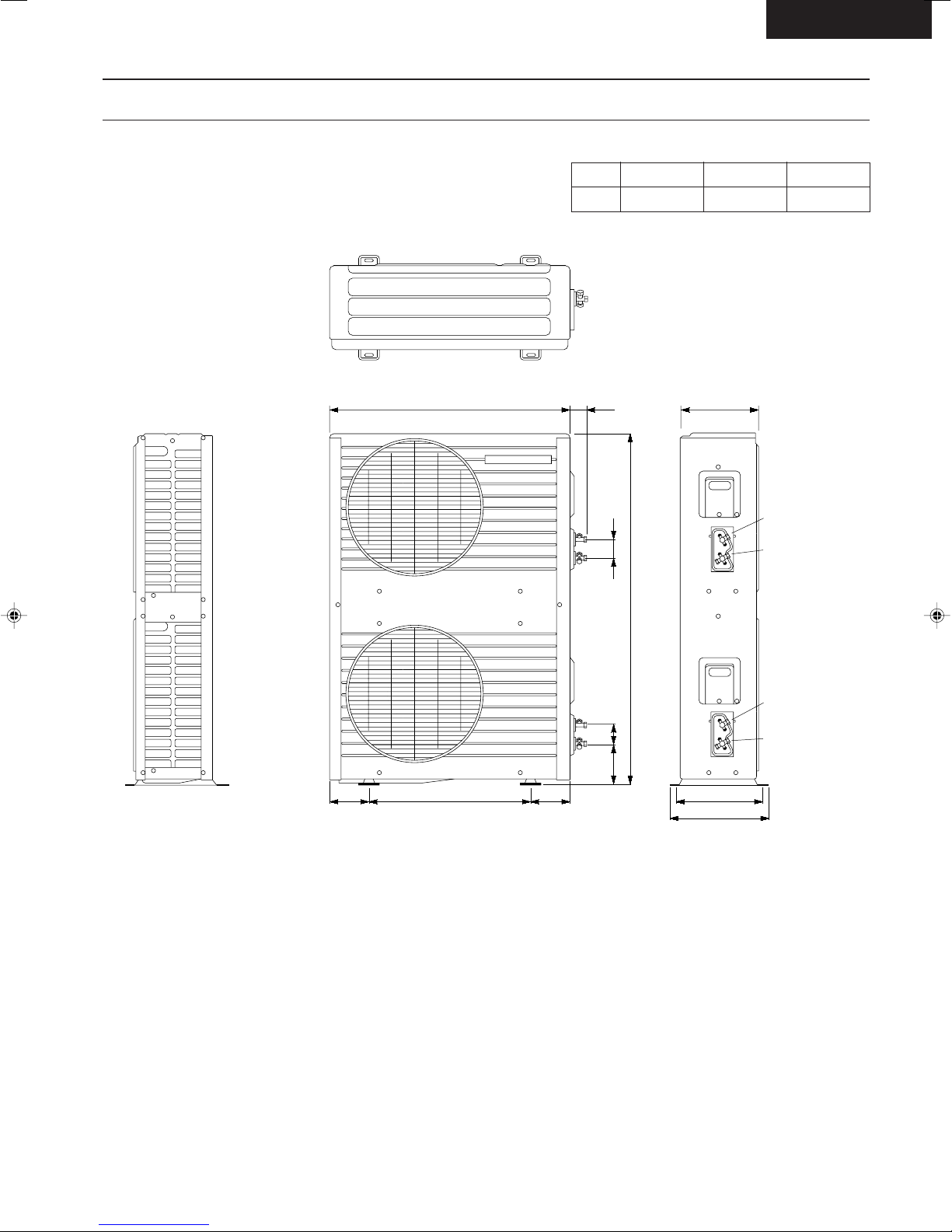
Dimensions
CS-MA70KE / CS-MA90KE / CS-MA120KE
<Front View>
Air intake
direction
790
175
Air outlet
direction
Left piping hole
290
55
<Back View>
60
Installation plate hooks
Drain ports
60
Gas
side
Liquid
side
(45)(410)
115
2100
48.5
290
52
Right piping hole
Remote control transmitter
57
61
34.5
142
16
Relative position between the indoor unit and the installation plate <Front View>
(40)
Installation plate
Indoor unit external
dimensions line
7
276
7
(60)
Left piping hole
Centre notch
100 100
Arrow
Centre
710
457
350
Arrow
Installation plate positioning gauge
– 11 –
Slot (2 places)
Slot (2 places)
(40)
(110)
13.5
Right piping hole
Dimensions
CU-MA180KE, CU-MA190KE, CU-MA240KE
780 57 245
A
CU-MA180K
985
CU-MA190K
1015
CS-MA90KE
CU-MA240K
1045
67
A
A
67104
105105 570 280
312
Unit A
Liquid side
2-way valve
Gas side
3-way valve
Unit B
Liquid side
2-way valve
Gas side
3-way valve
– 12 –
CS-A90KECS-MA90KE
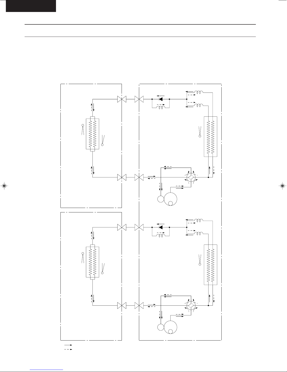
Refrigeration Cycle Diagram
CS-MA90KE / CU-MA180KE
CS-MA120KE / CU-MA240KE
CS-MA70KE / CU-MA190KE
CS-MA120KE
INDOOR OUTDOOR
INTAKE
TEMP.
SENSOR
HEAT EXCHANGER
(EVAPORATOR)
PIPE
TEMP.
SENSOR
2-WAY
VALVE
3-WAY
VALVE
CHECK VALVE
C3
CHECK VALVE
C1
C2
PIPE
TEMP.
SENSOR
(T.R.S)
HEAT EXCHANGER
(CONDENSER)
4-WAY VALVE
COMP.
C1
INTAKE
TEMP.
SENSOR
HEAT EXCHANGER
(EVAPORATOR)
COOLING
HEATING
PIPE
TEMP.
SENSOR
2-WAY
VALVE
3-WAY
VALVE
– 13 –
C3
PIPE
TEMP.
SENSOR
(T.R.S)
HEAT EXCHANGER
(CONDENSER)
4-WAY VALVE
COMP.
C1, C2, C3; CAPILARRY TUBE
C2
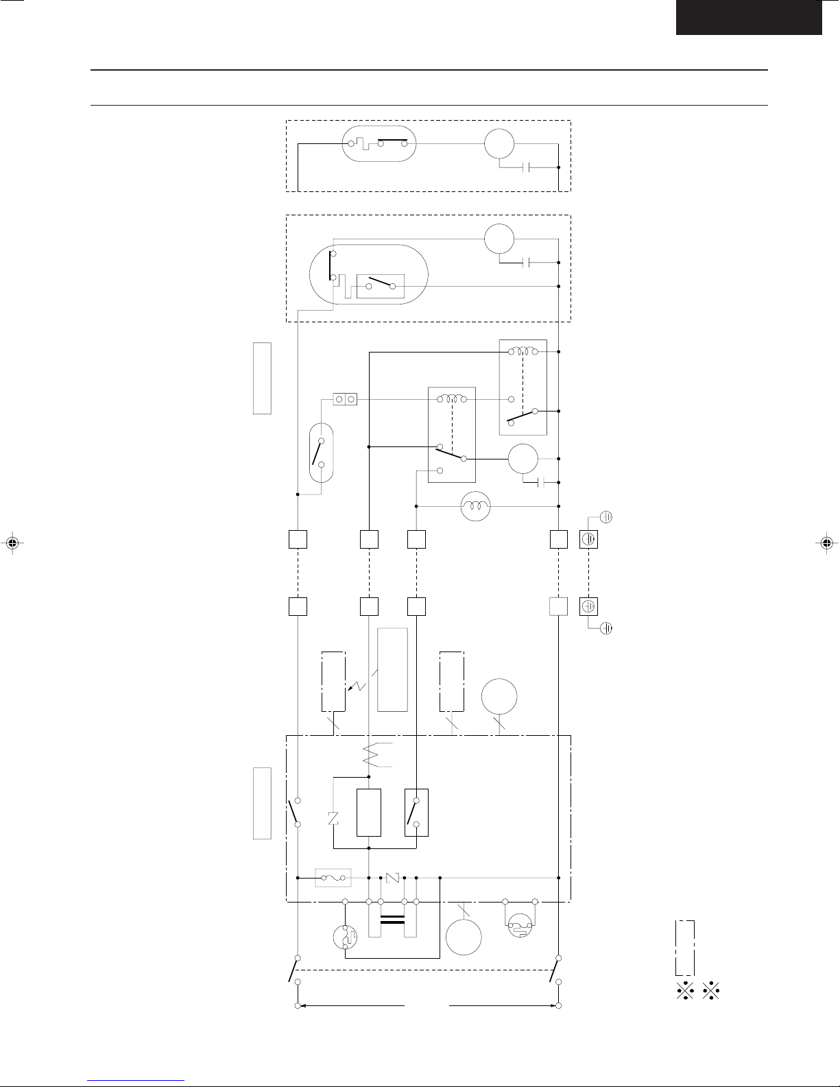
"C"
Indicates the electronic control unit.
Indicates the number of core wires. (Example:5C=5 core wires).
FUSE
ZNR1
ZNR2
3
4
1
TRANSFORMER
FM
CT1
STEPPING
3C
4C
5C
RECEIVER
P.C.B.
INDICATOR
P.C.B.
WIRELESS
REMOTE CONTROL
TRANSMITTER
2
2
1
4
3
FM
RELAY
B
RELAY A
COMP
COMP
O.L.P.
O.L.P.
FOR
CU-A120K/A90K
FOR
CU-A70K
MAIN
POWER SWITCH
SSR1
RY-HOT
SINGLE
50Hz
AC 220-240V
PHASE
INDOOR UNIT OUTDOOR UNIT
P.C.B.
MOTOR
TRS
4-WAY
VALVE
(3.15A)
3C
THERMAL FUSE
(102°C)
INDOOR
FAN MOTOR
THERMAL FUSE
(99°C)
RY-PWR
Block Diagram
CS-MA90KE
CS-MA90KE / CU-MA180KE
CS-MA120KE / CU-MA240KE
CS-MA70KE / CU-MA190KE
CS-MA120KE
– 14 –
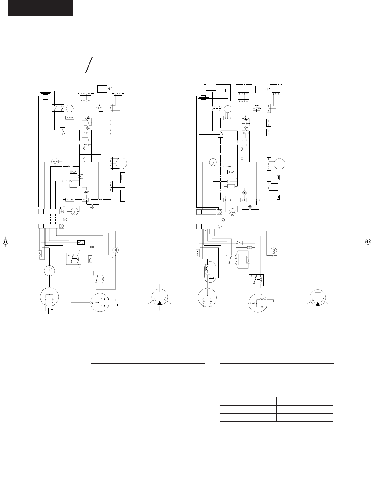
CS-MA90KE
Wiring Diagram
CS-MA70KE CU-MA190KE
CS-MA120KE
POWER SUPPLY CORD
CORE
123
MAIN SW
BL
W
THERMAL FUSE
(99°C)
W
BR
BR
W
B
P
L
4
AC(W)
HOT(R)
Y/G
B
123
CN-MTR (G)
AC (BR)
COMP (BL)
FM (B)
MOTOR
YRB
DISPLAY LAMP
CN-DISP (W)
4321
WWW
W
4321
REMOTE CONTROL No
CN-DISP (W)
FAN
ELECTRONIC
CONTROLLER
FUSE
2.0A
250V
T(BL)
ZNR1
RY-HOT
CR1
ZNR2
SSR1
T (BL)
CT1
WIRELESS
REMOTE
CONTROL
BA
123
CN-RCV (W)
CN-STM (G)CN-TH (Y)
4 231
5
1324
ELECTRONIC
CONTROLLER
(RECEIVER)
CN-RCV (W)
321
B
B
B
PUMP
SW DOWN SW
AUTO
BR
R
O
Y
P
(TEST RUN)
MOTOR
(FLAP)
(INTAKE TEMP.)
POWER SUPPLY CORD
CORE
123
MAIN SW
BL
W
THERMAL FUSE
(99°C)
W
BR
BR
W
B
4
P
L
Y/G
AC(W)
HOT(R)
FM (B)
B
FAN
MOTOR
YRB
123
CN-MTR (G)
AC (BR)
COMP (BL)
ZNR2
SSR1
RY-HOT
CR1
FUSE
2.0A
250V
DISPLAY LAMP
CN-DISP (W)
4321
W
CN-DISP (W)
ELECTRONIC
CONTROLLER
ZNR1
CT1
WWW
4321
REMOTE CONTROL No
BA
T(BL)
T (BL)
WIRELESS
REMOTE
CONTROL
123
CN-RCV (W)
CN-STM (G)CN-TH (Y)
4 231
5
1324
ELECTRONIC
CONTROLLER
(RECEIVER)
CN-RCV (W)
321
B
B
B
PUMP
(TEST RUN)
SW DOWN SW
AUTO
BR
R
O
MOTOR
(FLAP)
Y
P
(INTAKE TEMP.)
31
Y/G
2
B
4
4
W
R
THERMAL FUSE
OUTDOOR UNIT
TERMINAL
R
428
INDOOR UNIT TERMINAL
BL
CAPACITOR
ELECTROLYTIC
BL
OVER LOAD
PROTECTOR
COMPRESSOR
21
3
1
Y
R
CAPACITOR
3
312
GRY
REMARKS:
B :BLUE
BR :BROWN
BL :BLACK
W :WHITE
R :RED
O :ORANGE
P :PINK
Y/G :YELLOW/
GREEN
GRY:GRAY
(102°C)
BL
GRY
CN-T(W)CN-FUSE (B)
R
BL
76
BR
TRANSFORMER
W
TRS
BL
MAGNETIC RELAY B
BL
R
T (BL) T (BL)
BLR
BL
BL
CAPACITOR
ELECTROLYTIC
SENSOR SENSOR
(PIPE TEMP.)
GRY
COIL
REVERSING VALVE
824
67
MAGNETIC RELAY A
B
B
B
FAN MOTOR
B
R
CAPACITOR
TRADE MARK
COMPRESSOR TERMINAL
Y
Resistance of Outdoor Fan Motor Windings
CONNECTION
BLUE - YELLOW
YELLOW - RED
YELLOW
C
SR
REDBLUE
CWA95245 (Ω)
312.9
419.7
INDOOR UNIT TERMINAL
BL
CAPACITOR
ELECTROLYTIC
BL
OVER LOAD
COMPRESSOR
CN-T(W)CN-FUSE (B)
R
BL
76
BR
R
TRANSFORMER
W
TRS
BL
MAGNETIC RELAY B
BL
T (BL) T (BL)
BLR
BL
GRY
BL
CAPACITOR
ELECTROLYTIC
67
B
FAN MOTOR
824
MAGNETIC RELAY A
B
21
3
312
W
PROTECTOR
2
Y
R
CAPACITOR
B
4
4
1
W
31
Y/G
R
THERMAL FUSE
OUTDOOR UNIT
TERMINAL
R
428
GRY
(102°C)
BL
GRY
Y
Resistance of Compressor Windings
CS-MA70KE / CU-MA190KE
CONNECTION
C-R
C-S
CS-MA120KE / CU-MA190KE
CONNECTION
C-R
C-S
SENSOR SENSOR
(PIPE TEMP.)
COIL
REVERSING VALVE
B
B
CAPACITOR
R
2RS122D5AB02 (Ω)
5.63
12.17
2KS224D5AC02 (Ω)
2.45
3.86
YELLOW
C
SR
REDBLUE
TRADE MARK
COMPRESSOR TERMINAL
– 15 –
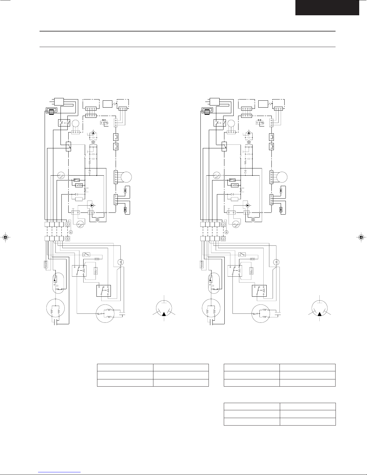
Wiring Diagram
CS-MA90KE / CU-MA180KE
CS-MA120KE / CU-MA240KE
CS-MA90KE
CORE
INDOOR UNIT TERMINAL
BL
CAPACITOR
ELECTROLYTIC
BL
OVER LOAD
POWER SUPPLY CORD
BR
123
MAIN SW
BR
BL
W
THERMAL FUSE
(99°C)
W
21
3
4
4
312
W
PROTECTOR
1
2
Y
Y/G
B
4
MOTOR
YRB
123
CN-MTR (G)
P
AC (BR)
COMP (BL)
L
AC(W)
W
HOT(R)
FM (B)
B
31
Y/G
OUTDOOR UNIT
TERMINAL
428
GRY
FAN
FUSE
3.15A
250V
RY-HOT
CR1
ZNR2
SSR1
R
THERMAL FUSE
(102°C)
R
GRY
R
BL
DISPLAY LAMP
CN-DISP (W)
4321
W
CN-DISP (W)
ELECTRONIC
CONTROLLER
CT1
CN-T(W)CN-FUSE (B)
W
TRS
BL
BL
76
MAGNETIC RELAY B
BL
BR
WWW
4321
REMOTE CONTROL No
T(BL)
ZNR1
T (BL)
R
TRANSFORMER
WIRELESS
REMOTE
CONTROL
BA
T (BL) T (BL)
BLR
BL
GRY
BL
CAPACITOR
ELECTROLYTIC
67
B
CN-RCV (W)
CN-STM (G)CN-TH (Y)
824
MAGNETIC RELAY A
ELECTRONIC
CONTROLLER
(RECEIVER)
CN-RCV (W)
321
B
123
B
B
PUMP
SW DOWN SW
AUTO
BR
R
O
Y
4 231
P
5
1324
SENSOR SENSOR
B
(TEST RUN)
MOTOR
(FLAP)
(INTAKE TEMP.)
(PIPE TEMP.)
COIL
REVERSING VALVE
YELLOW
POWER SUPPLY CORD
DISPLAY LAMP
CN-DISP (W)
4321
Y/G
MAIN SW
BL
W
THERMAL FUSE
3
312
W
2
Y
BR
123
BR
(99°C)
4
4
1
B
4
MOTOR
YRB
123
CN-MTR (G)
P
AC (BR)
COMP (BL)
L
AC(W)
W
HOT(R)
FM (B)
B
31
Y/G
OUTDOOR UNIT
TERMINAL
428
GRY
FAN
ZNR2
R
THERMAL FUSE
R
CORE
W
INDOOR UNIT TERMINAL
21
BL
CAPACITOR
ELECTROLYTIC
BL
OVER LOAD
PROTECTOR
C
SSR1
RY-HOT
CR1
(102°C)
GRY
FUSE
3.15A
250V
R
BL
W
CN-DISP (W)
ELECTRONIC
CONTROLLER
CT1
CN-T(W)CN-FUSE (B)
W
TRS
BL
BL
76
MAGNETIC RELAY B
BL
BR
WWW
4321
REMOTE CONTROL No
T(BL)
ZNR1
T (BL)
R
TRANSFORMER
T (BL) T (BL)
BLR
BL
BL
ELECTROLYTIC
WIRELESS
REMOTE
CONTROL
BA
GRY
CAPACITOR
824
67
B
ELECTRONIC
CONTROLLER
(RECEIVER)
CN-RCV (W)
321
B
123
B
B
CN-RCV (W)
PUMP
(TEST RUN)
SW DOWN SW
AUTO
BR
R
O
MOTOR
(FLAP)
Y
CN-STM (G)CN-TH (Y)
4 231
P
5
(INTAKE TEMP.)
1324
SENSOR SENSOR
(PIPE TEMP.)
MAGNETIC RELAY A
B
COIL
REVERSING VALVE
YELLOW
C
FAN MOTOR
B
R
CAPACITOR
COMPRESSOR
CAPACITOR
Y
B
R
W
REMARKS:
B : BLUE
BR : BROWN
BL : BLACK
W : WHITE
R : RED
O : ORANGE
Resistance of Outdoor Fan Motor Windings
CONNECTION
BLUE - YELLOW
YELLOW - RED
P : PINK
Y/G : YELLOW/
GREEN
GRY : GRAY
FAN MOTOR
B
R
B
CAPACITOR
SR
REDBLUE
TRADE MARK
COMPRESSOR TERMINAL
B
COMPRESSOR TERMINAL
TRADE MARK
SR
REDBLUE
COMPRESSOR
CAPACITOR
B
R
Y
W
Resistance of Compressor Windings
CS-MA90KE / CU-MA180KE
CWA95245 (Ω)
312.9
419.7
CONNECTION
C-R
C-S
2PS164D3AD02 (Ω)
3.43
4.76
CS-MA120KE / CU-MA240KE
CONNECTION
C-R
C-S
2KS224D5AC02 (Ω)
2.45
3.86
– 16 –
 Loading...