


© 2006 Panasonic HA Air-Conditioning (M) Sdn Bhd
(11969-T). All rights reserved. Unauthorized copying
and distribution is a violation of law.
Order No. MAC0608038C2
Air Conditioner
CS-F28DTE5 CU-L50DBE5
CS-F50DTE5 CU-L50DBE5
TABLE OF CONTENTS
PAGE PAGE
1 Service Information---------------------------------------------- 2
1.1. Operation range-------------------------------------------- 2
2 Specifications ----------------------------------------------------- 3
2.1. Product Specification------------------------------------- 3
3 Refrigeration Cycle ---------------------------------------------- 5
4 Block Diagram----------------------------------------------------- 6
4.1. CU-L50DBE5----------------------------------------------- 6
5 Wiring Diagram---------------------------------------------------- 7
5.1. CU-L50DBE5----------------------------------------------- 7
6 Electronic Circuit Diagram------------------------------------ 8
6.1. CU-L50DBE5----------------------------------------------- 8
7 Installation Instruction------------------------------------------ 9
7.1. Outdoor Unit Installation----------------------------------9
8 Technical Data--------------------------------------------------- 20
8.1. Sound Data------------------------------------------------ 20
8.2. Capacity And Power Consumption------------------21
8.3. Safety device---------------------------------------------- 28
8.4. Operating characteristics-------------------------------29
9 Exploded View and Replacement Parts List----------- 30
9.1. Outdoor Unit----------------------------------------------- 30
Please file and use this manual together with the service manual for Model No. CS-F24DTE5 CU-L24DBE5,
CS-F28DTE5 CU-L28DBE5, CS-F34DTE5 CU-L34DBE5, CS-F43DTE5 CU-L43DBE5, CS-F50DTE5 CUL50DBE8, Order No. MAC0504060C2.
2
1 Service Information
1.1. Operation range
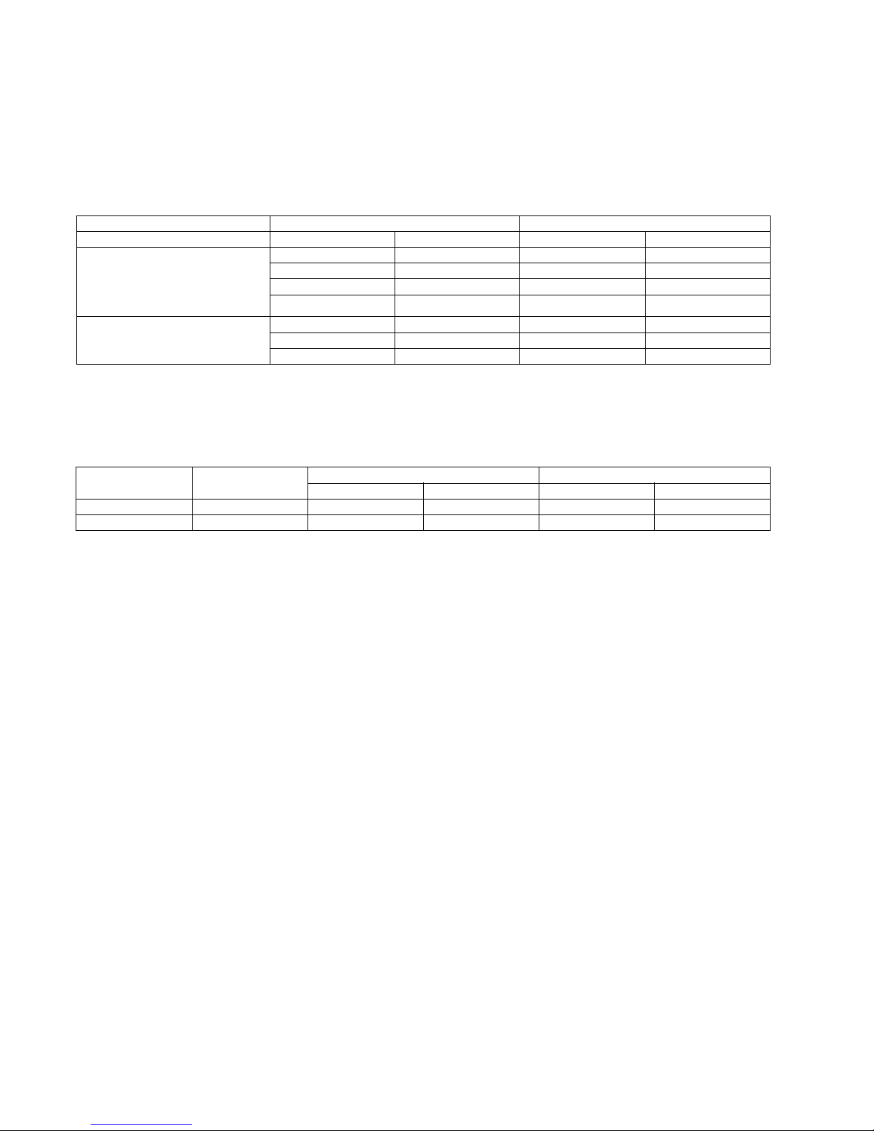
1.1.1. Power supply
The applicable voltage range for each unit is given in the following table. The working voltage among the three phases must be
balanced within a 3% deviation from each voltage at the compressor terminals. The starting voltage must be higher than 85% of the
rated voltage.
1.1.2. Indoor and outdoor temperature
• Model 50Hz CU-L24DBE5, CU-L28DBE5, CU-L34DBE5, CU-L43DBE5, CU-L50DBE5, CU-L50DBE8
MODEL Unit Main Power Applicable Voltage
CU- Phase, Volts Hz Max Min
L24DBE5
L28DBE5
L34DBE5
L43DBE5
L50DBE5
1~240 50 264 216
1~220 50 242 198
1~230 50 253 207
1~240 50 264 216
L50DBE8 3N~380 50 418 342
3N~400 50 440 360
3N~415 50 457 374
Operating Hz Indoor Temp. (D.B./W.B.) (°C) Outdoor Temp. (D.B./W.B.) (°C)
MaxMinMaxMin
Cooling 50 32/23 21/15 43/- -15/Heating 50 27/- 16/- 24/18 -20/-
3
2 Specifications
2.1. Product Specification
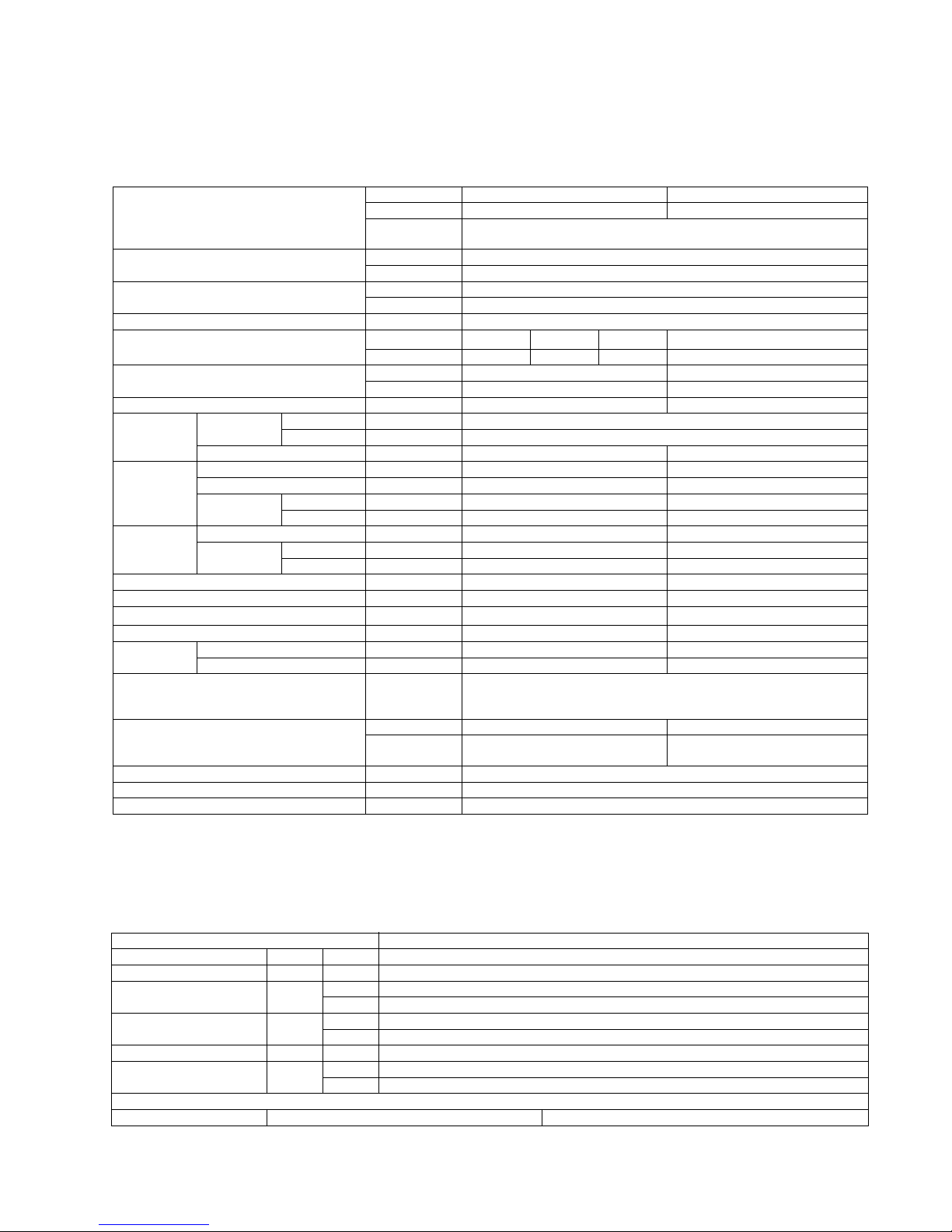
2.1.1. CS-F28DTE5 CU-L50DBE5 (For Australia only)
1. Cooling capacities are based on indoor temperature of 27°C D.B. (80.6°F D.B.), 19.0°C W.B. (66.2°F W.B.) and outdoor air
temperature of 35°C D.B. (95°F D.B.), 24°C W.B. (75.2°F W.B.)
2. Heating capacities are based on indoor temperature of 20°C D.B. (68°F D.B.) and outdoor air temperature of 7°C D.B. (44.6°F
D.B.), 6°C W.B. (42.8°F W.B.)
ELECTRICAL DATA (50 Hz)
ITEM / MODEL
Indoor Unit Outdoor Unit
Main Body CS-F28DTE5 x 2 CU-L50DBE5
Remote
Control
CZ-RD513C (Wired)
CZ-RL513T (Wireless)
Cooling Capacity kW 14.0
BTU/h 47,700
Heating Capacity kW 16.0
BTU/h 54,600
Refrigerant Charge-less m 30
Standard Air Volume for High,
m
3
/min
Hi 18 x 2 Me 16 Lo 14 Hi 98
Medium and Low Speed cfm 636 x 2 565 495 3460
Outside Dimension (H x W x D) mm 210 x 1245 x 700 1340 x 900 x 320
inch 8-9/32 x 49-1/64 x 27-9/16 52-7/8 x 35-7/16 x 12-19/32
Net Weight kg (lbs) 33 (73) 110 (242)
Piping
Connection
Refrigerant
Gas mm (inch) O.D Ø 15.88 (5/8) Flared Type
Liquid mm (inch) O.D Ø 9.53 (3/8) Flared Type
Drain mm O.D Ø 20 I.D Ø 20 x 1
Compressor Type, Number of Set - Hermetic - 2P (Rotary), 1
Starting Method - DC - INV control
Motor
Type - 4-pole single phase brushless motor
Rated Output kW - 3.8
Fan Type, Number of Set Sirocco fan-4 Mix flow fan - 1
Motor
Type 4-pole single phase induction motor 6-pole single phase induction motor
Rated Output kW 0.04 x 2 0.07 x 2
Air-heat Exchanger (Row x Stage x FPI) Slit-fin type (2 x 12 x 18) Corrugate-fin type (2 x 51 x 18)
Refrigerant Control - Exp. Valve
Refrigerant Oil (Charged)
cm
3
- F V50S (1200)
Refrigerant (Charged) R410A kg (oz) - 3.50 (123)
Running
Adjustment
Control Switch Wireless or Wired Remote Control Room Temperature Thermostat -
Safety Devices Temperature, current and pressure protection control for compressor,
Internal thermostat for FM, High pressure switch,
Current trans, Crankcase heater
Noise Level dB (A) Hi 45 Lo 41 Cooling 55, Heating 57
Power level dB
Cooling : Hi 62 Lo 58
Heating : Hi 62 Lo 58
Cooling 69, Heating 71
Moisture Removal L/h (Pt/h) 9.0 (19.0)
EER W/W 2.91
COP W/W 3.34
ITEM / MODEL Condition by JIS-B8615
Volts V 240
Phase Single
Power Consumption kW Cool 4.81
Heat 4.79
Running Current A Cool 21.0
Heat 20.9
Starting Current A 21.0
Power Factor % Cool 95
Heat 95
*Power Factor means total figure of compressor, indoor fan motor and outdoor fan motor.
Panasonic Power source AC, 1~240V 50Hz
4
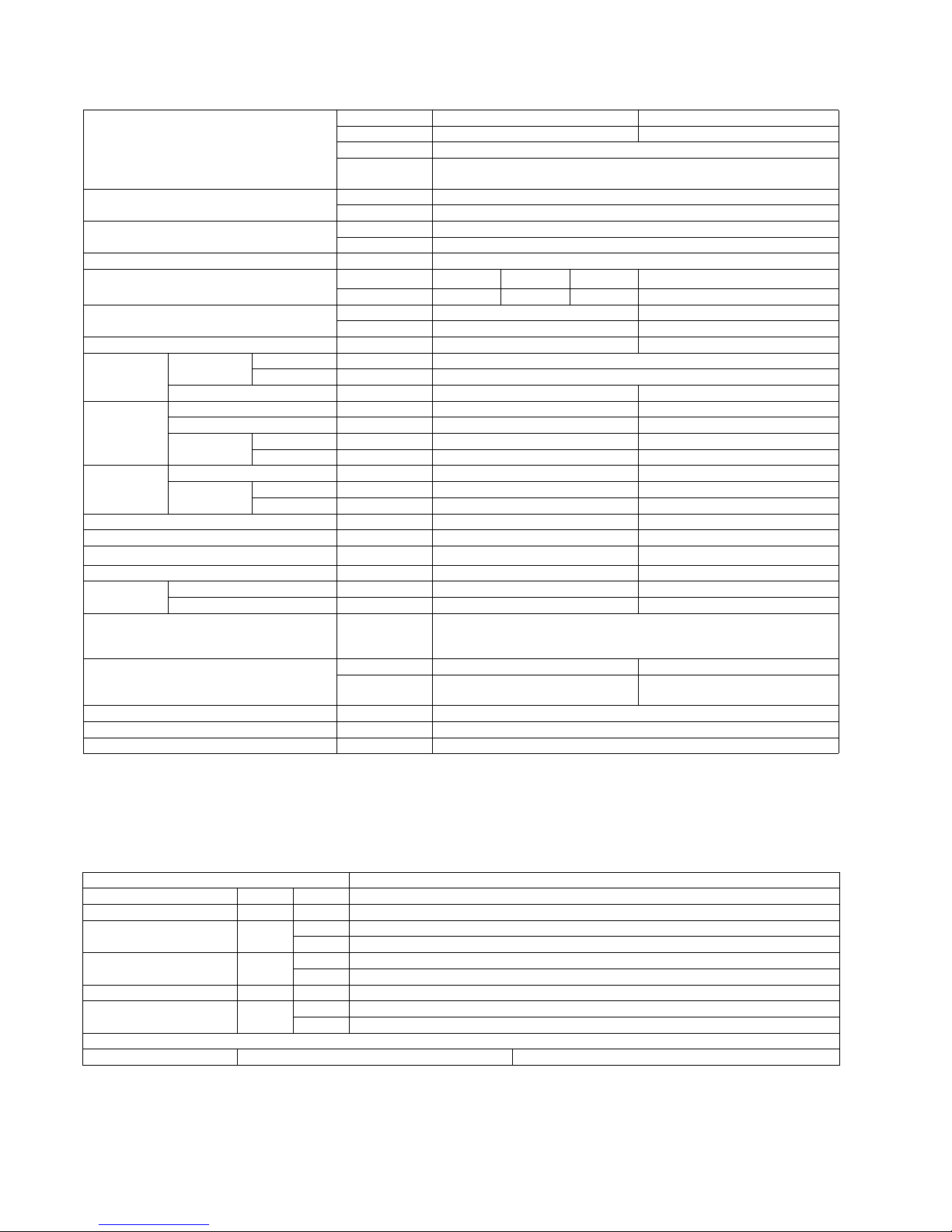
2.1.2. CS-F50DTE5 CU-L50DBE5 (For Australia only)
1. Cooling capacities are based on indoor temperature of 27°C D.B. (80.6°F D.B.), 19.0°C W.B. (66.2°F W.B.) and outdoor air
temperature of 35°C D.B. (95°F D.B.), 24°C W.B. (75.2°F W.B.)
2. Heating capacities are based on indoor temperature of 20°C D.B. (68°F D.B.) and outdoor air temperature of 7°C D.B. (44.6°F
D.B.), 6°C W.B. (42.8°F W.B.)
ELECTRICAL DATA (50 Hz)
ITEM / MODEL
Indoor Unit Outdoor Unit
Main Body CS-F50DTE5 CU-L50DBE5
Panel CZ-BT03P
Remote
Control
CZ-RD513C (Wired)
CZ-RL513T (Wireless)
Cooling Capacity kW 14.0
BTU/h 47,700
Heating Capacity kW 16.0
BTU/h 54,600
Refrigerant Charge-less m 30
Standard Air Volume for High,
m
3
/min
Hi 32 Me 28 Lo 26 Hi 98
Medium and Low Speed cfm 1130 1040 960 3460
Outside Dimension (H x W x D) mm 250 x 1600 x 700 1340 x 900 x 320
inch 9-27/32 x 62-31/32 x 27-9/16 52-7/8 x 35-7/16 x 12-19/32
Net Weight kg (lbs) 47 (104) 105 (231)
Piping
Connection
Refrigerant
Gas mm (inch) O.D Ø 15.88 (5/8) Flared Type
Liquid mm (inch) O.D Ø 9.53 (3/8) Flared Type
Drain mm O.D Ø 20 I.D Ø 20 x 1
Compressor Type, Number of Set - Hermetic - 2P (Rotary), 1
Starting Method - DC - INV control
Motor
Type - 4-pole single phase brushless motor
Rated Output kW - 3.8
Fan Type, Number of Set Sirocco fan-4 Mix flow fan - 2
Motor
Type 4-pole single phase induction motor 6-pole single phase induction motor
Rated Output kW 0.14 0.07 x 2
Air-heat Exchanger (Row x Stage x FPI) Slit-fin type (3 x 14 x 18) Corrugate-fin type (2 x 51 x 18)
Refrigerant Control - Exp. Valve
Refrigerant Oil (Charged)
cm
3
- FV50S (1200)
Refrigerant (Charged) R410A kg (oz) - 3.50 (123)
Running
Adjustment
Control Switch Wireless or Wired Remote Control Room Temperature Thermostat -
Safety Devices Temperature, current and pressure protection control for compressor,
Internal thermostat for FM, High pressure switch,
Current trans, Crankcase heater
Noise Level dB (A) Hi 50 Lo 46 Cooling 55, Heating 57
Power level dB
Cooling : Hi 67 Lo 63
Heating : Hi 67 Lo 63
Cooling 69, Heating 71
Moisture Removal L/h 9.0
EER W/W 2.91
COP W/W 3.34
ITEM / MODEL Condition by JIS-B8615
Volts V 240
Phase Single
Power Consumption kW Cool 4.81
Heat 4.79
Running Current A Cool 21.0
Heat 20.9
Starting Current A 21.0
Power Factor % Cool 95
Heat 95
*Power Factor means total figure of compressor, indoor fan motor and outdoor fan motor.
Panasonic Power source AC, 1~240V 50Hz
5
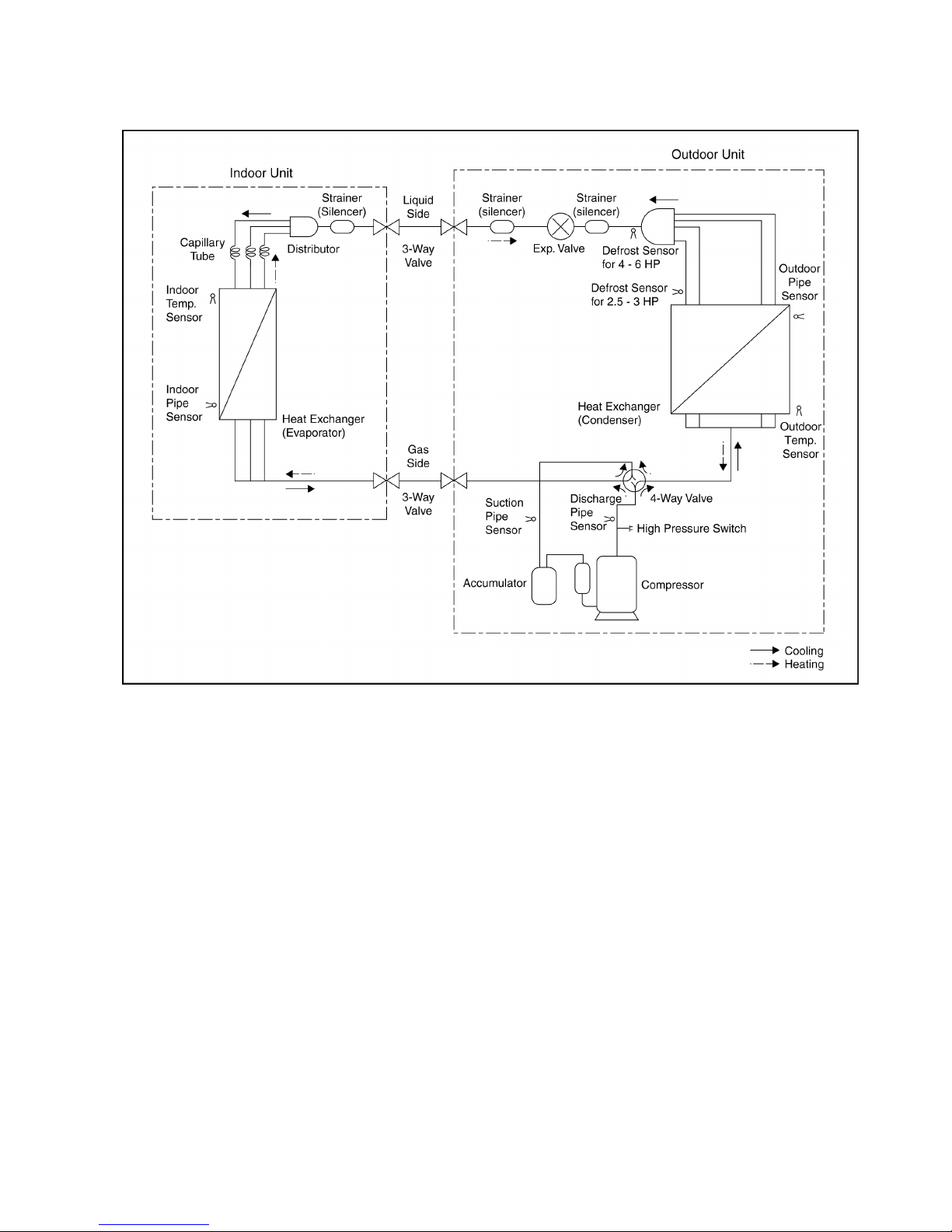
3 Refrigeration Cycle

6
4 Block Diagram
4.1. CU-L50DBE5

7
5 Wiring Diagram
5.1. CU-L50DBE5

8
6 Electronic Circuit Diagram
6.1. CU-L50DBE5
9
7 Installation Instruction
7.1. Outdoor Unit Installation
• As to indications with illustration
• After installation work has been completed, do not only make sure that the unit is free from any abnormal condition through the
execution of trial run but also explain how to use and how to perform maintenance of this unit to the customer according to the
instruction manual.
• In addition, request the customer to keep this manual for installation work together with instruction manual.
AIR CONDITIONERS OUTDOOR UNIT INSTALLATION INSTRUCTIONS
Precautions in terms of safety
Carry out installation work with reliability after through reading of this “Precautions in terms of safety”.
•
Precautions shown here are differentiated between and . Those that have much chances for
leading to significant result such as fatality or serious injury if wrong installation would have been carried out are listed compiling
them especially into the column of
.
However, even in the case of items which are listed in the column of , such items also have a chance for leading
to significant result depending on the situations.
In either case, important descriptions regarding the safety are listed, then observe them without fail.
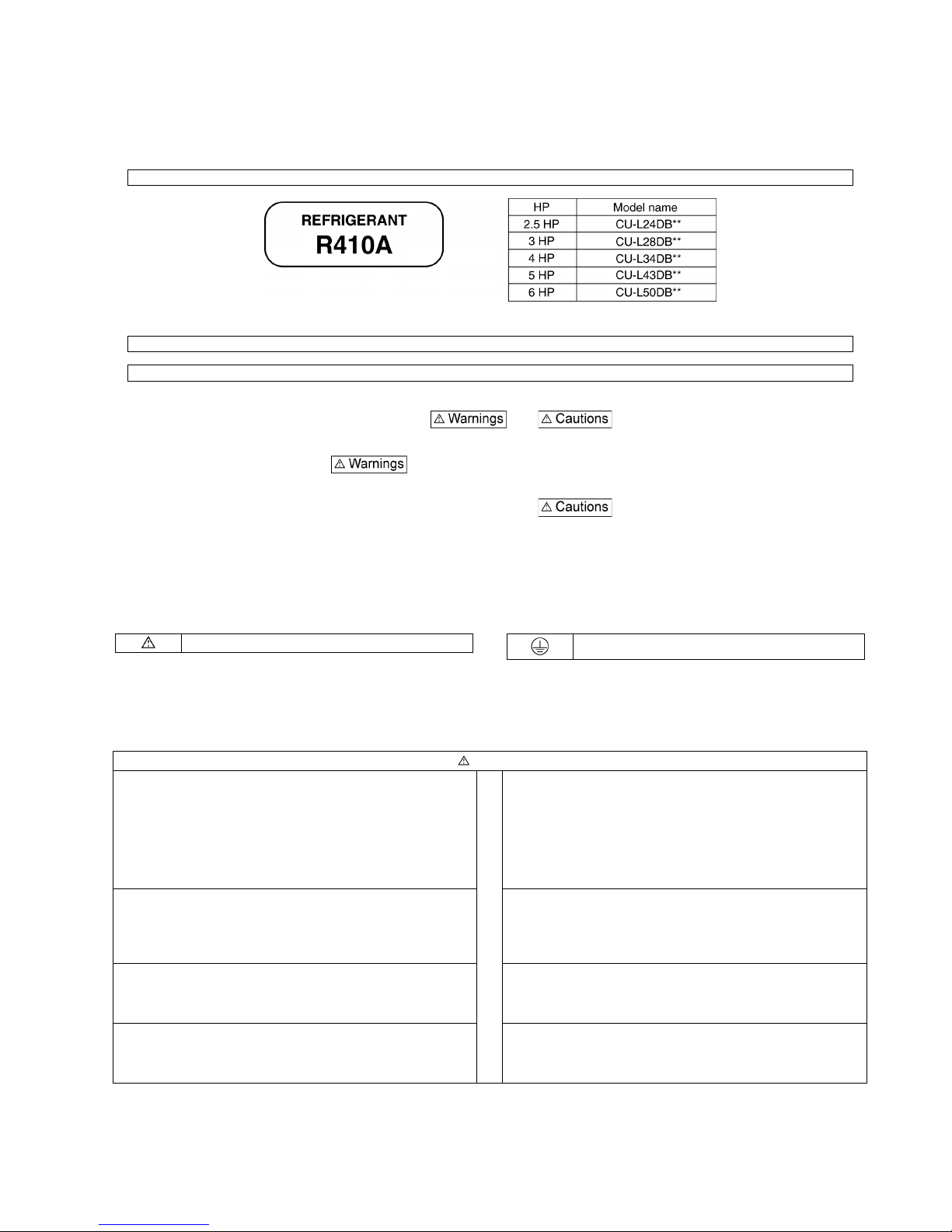
This mark means “Caution” or “Warning”. This mark means “Earth”.
Warnings
▲ The appliance must be installed by technician, who takes into
account the requirements given by ISO5149 or eventual
equivalent requirements.
▲ If installing inside a small room, measures should be taken to
prevent refrigerant levels from building up to critical
concentrations in the event of a refrigerant leak occurring.
Please discuss with the place of purchase for advice on what
measures may be necessary to prevent critical concentrations
being exceeded. If the refrigerant leaks and reaches critical
concentration levels, there is the danger that death from
suffocation may result.
▲ As to installation, request the distributor or vendor to perform it.
Imperfection in installation caused by that having been carried
out by the customer himself may leads to water leakage, electric
shock, fire, etc.
▲ Securely attach the protective covers for the outdoor unit
connection cables and power cord so that they do not lift up
after installation. If the covers are not properly attached and
installed, the terminal connections may overheat, and fire or
electric shock may result.
▲ Carry out the installation work with reliability according to this
manual for installation work.
Imperfection in installation leads to water leakage, electric
shock, fire, etc.
▲ Switch off all supplies before accessing any electrical part.
▲ Carry out the installation work with reliability on the place that
can bear the weight of this unit sufficiently. Insufficient strength
leads to injury due to falling of the unit.
▲ If refrigerant gas escapes during installation, ventilate the
affected area. If the refrigerant gas comes into contact with
sparks or naked flames, it will cause toxic gases to be
generated.
10
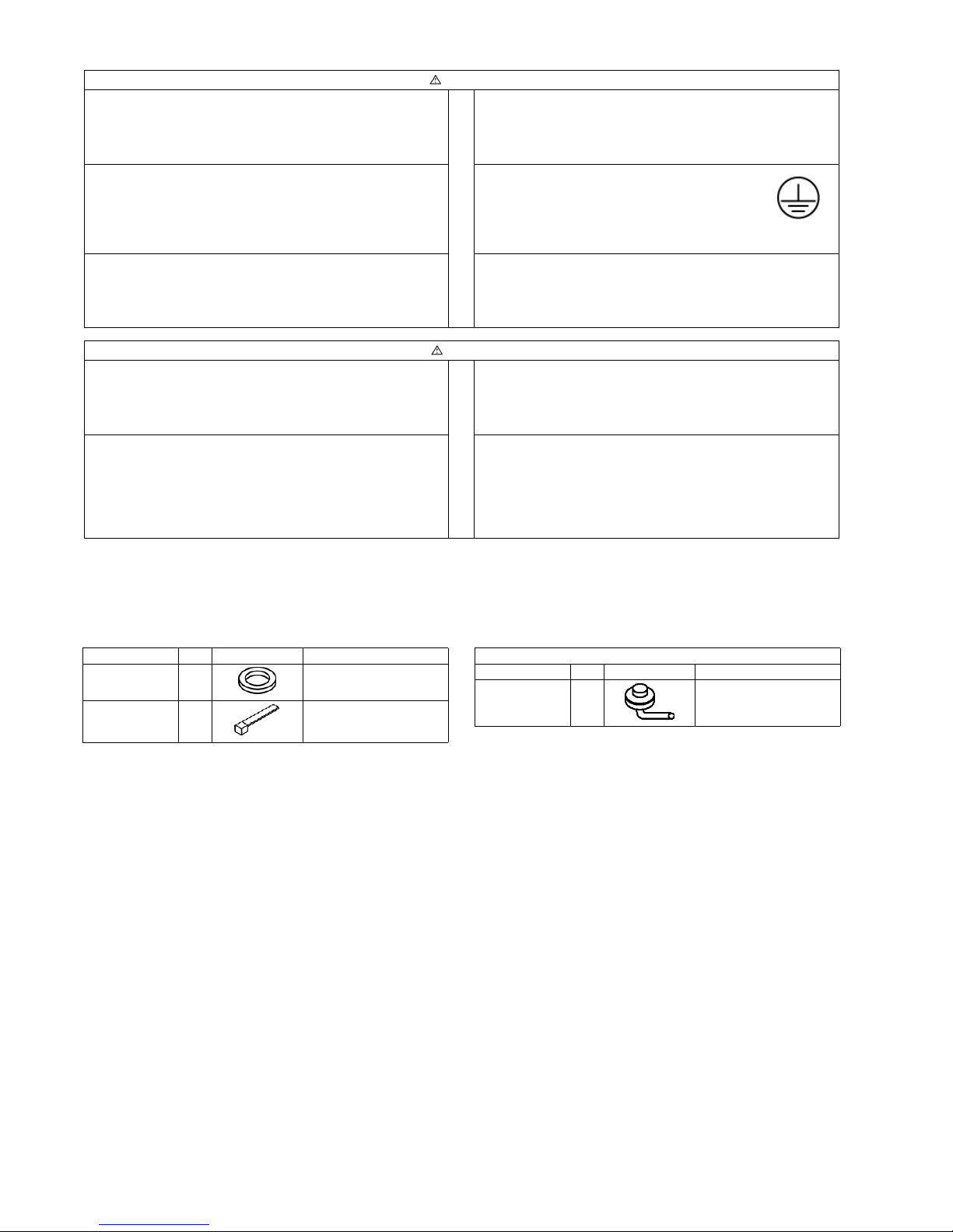
7.1.1. Accessories supplied with outdoor unit
• The following parts are supplied as accessories with each outdoor unit.
Check that all accessory parts are present before installing the outdoor unit.
7.1.2. Before installation work
• This product is using new refrigeration (R410A). The basic way of installation work is the same as usual, but water and impurities
should be controlled more strictly than before due to characteristic of refrigerating machine oil. Therefore, selection of materials
to use and processing, storing and brazing need appropriate construction and control.
1. Tools and materials
There are tools and materials for both new refrigeration and usual refrigeration you can use together and for either two of
them you can use. Use the below for new refrigeration.
• Vacuum pump (with back flow preventor system)
• Gas leakage detection warning device
• Gauge manifold
• Charge hose
2. Installation work
a. Brazing work
Brazing work needs replacing air inside pipe with nitrogen gas in order to prevent oxidization scale from occurring. This
is called nitrogen replacement, and one of very important work in brazing refrigerant piping. (Oxidation preventive is
not possible to use)
▲ The unit must be installed in accordance with applicable national
and local regulations. Any electrical work should only be carried
out by qualified technician and use exclusive circuits without fail.
Presence of insufficient capacity in power circuit or imperfection
in execution leads to electric shock, fire, etc.
▲ When performing piping work do not mix air except for specified
refrigerant (R410A) in refrigeration cycle. It causes capacity
down, and risk of explosion and injury due to high tension inside
the refrigerant cycle.
▲ Wiring shall be connected securely using specified cables and
fix them securely so that external force of the cables may not
transfer to the terminal connection section.
Imperfect connection and fixing leads to fire, etc.
▲ Earth
This equipment must be properly earthed. Earth
line must not be connected to gas pipe, water
pipe, lightning rod and telephone. Otherwise, it
may cause electrical shock in case the
equipment breakdown or has leakage current.
▲ Installation of Earth Leakage Current Breaker
This equipment must be installed with earth leakage current
breaker.
Otherwise, it may cause electrical shock and fire in case the
equipment breakdown or has leakage current.
Cautions
▲ Do not install the unit at the place where the possibility of
inflammable gas leakage exists. If such gas leakages should
arise and the gas builds up around the unit, such situation may
lead to ignition.
▲ Drain piping should be made to ensure secure drainage
according to the manual for installation work and carry out the
thermal insulation to prevent the occurrence of condensation.
Imperfection in piping work leads to water leakage and may
cause the house and property, etc. to become wet.
▲ Position the indoor unit and outdoor unit, power cords and
indoor/outdoor unit connection cables in a way so that they are at
least 1 meter away from televisions and radios.
This is to avoid problem such as interference with picture and/or
sound. (However, note that depending on the electromagnetic
wave conditions, interference may still occur even if the
separation distance is more than 1 meter.)
Warnings
Part name Q’ty Diagram Application
Protective
bushing
2 For protecting electrical
wires
Banding
strap
3 For tying electrical wires
together
Heat pump-types only
Part name Q’ty Diagram Application
Drain elbow AS 1 For connecting the drain
pipe (with ring seat)
 Loading...