

Panasonic CS-E12RB4UW, CS-E18RB4UW, CU-E12RB4U, CU-E18RB4U service manual
Order No: PAPAMY1503095CE
TEM P
O
TIMER
S
O
N
O
1
2
C
K
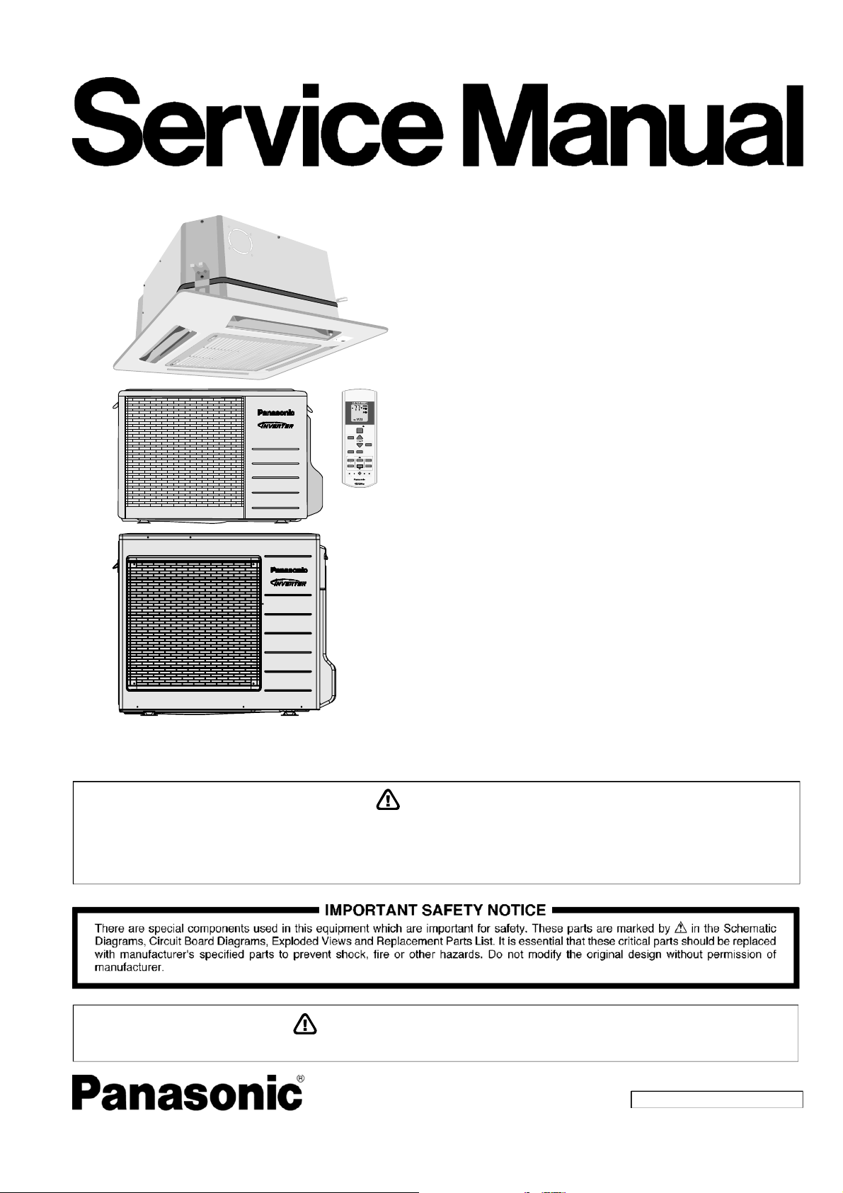
Air Conditioner
Indoor Unit Outdoor Unit
CS-E12RB4UW
CS-E18RB4UW
CU-E12RB4U
CU-E18RB4U
E
S
O
L
C
N
E
P
O
N
E
P
O
E
S
O
L
C
O
F
F
/
O
N
A
I
R
T
I
M
S
P
W
O
E
W
R
I
N
E
G
R
AUTO
HEAT
COOL
DRY
FAN
MODE
POWERFUL/
QUIET
TIMER
123
FF
SETCHECK CLOCK RESET
FAN
SPEED
AIR
SWING
OFF/ON
FF/ON
TEMP
AIRSWING
FANSPEED
SET
ET
3
CANCEL
CANCELONOFF
AC RC
HEC
Destination
USA
Canada
This service information is designed for experienced repair technicians only and is not designed for use by the general public.
It does not contain warnings or cautions to advise non-technical individuals of potential dangers in attempting to service a product.
Products powered by electricity should be serviced or repaired only by experienced professional technicians. Any attempt to service
or repair the products dealt with in this service information by anyone else could result in serious injury or death.
WARNING
In order to avoid frostbite, be assured of no refrigerant leakage during the installation or repairing of refrigerant circuit.
PRECAUTION OF LOW TEMPERATURE
© Panasonic Corporation 2015

TABLE OF CONTENTS
PAGE PAGE
1. Safety Precautions ............................................. 3
2. Specifications ..................................................... 5
3. Features ............................................................. 11
4. Location of Controls and Components .......... 12
4.1 Indoor Unit .................................................. 12
4.2 Outdoor Unit ............................................... 12
4.3 Remote Control .......................................... 12
5. Dimensions ....................................................... 13
5.1 Indoor Unit .................................................. 13
5.2 Outdoor Unit ............................................... 14
6. Refrigeration Cycle Diagram ........................... 15
7. Block Diagram .................................................. 16
7.1 CS-E12RB4UW CU-E12RB4U ................. 16
7.2 CS-E18RB4UW CU-E18RB4U ................. 17
8. Wiring Connection Diagram ............................ 18
8.1 Indoor Unit .................................................. 18
8.2 Outdoor Unit ............................................... 19
9. Electronic Circuit Diagram .............................. 21
9.1 Indoor Unit .................................................. 21
9.2 Outdoor Unit ............................................... 22
10. Printed Circuit Board ....................................... 24
10.1 Indoor Unit .................................................. 24
10.2 Outdoor Unit ............................................... 26
11. Installation Instruction ..................................... 29
11.1 Indoor Unit .................................................. 29
11.2 Outdoor Unit ............................................... 35
12. Operation Control ............................................. 40
14.2 Cooling Only Operation
(Single connection Only, Multi connection
please refer to Multi outdoor manual) .........52
14.3 Remote Control Button ...............................53
14.4 Outdoor PCB Test Run Operation
(For Pump Down/Servicing Purpose) .........54
15. Troubleshooting Guide ....................................56
15.1 Refrigeration Cycle System ........................56
15.2 Breakdown Self Diagnosis Function ...........58
15.3 Error Codes Table ......................................59
15.4 Self-diagnosis Method ................................61
16. Disassembly and Assembly Instructions ......85
16.1 Disassembly of Parts ..................................85
16.2 Outdoor Electronic Controller Removal
Procedure ...................................................88
17. Technical Data ..................................................90
17.1 Cool Mode Performance Data ....................90
17.2 Heat Mode Performance Data ....................92
18. Service Data ......................................................93
18.1 Cool Mode Outdoor Air Temperature
Characteristic ..............................................93
18.2 Heat Mode Outdoor Air Temperature
Characteristic ..............................................95
18.3 Piping Length Correction Factor .................97
19. Exploded View and Replacement Parts
List .....................................................................99
19.1 Indoor Unit ..................................................99
19.2 CZ-BT20U (Front Grille Complete) .......... 103
19.3 Outdoor Unit ............................................ 105
12.1 Basic Function ............................................ 40
12.2 Indoor Fan Motor Operation ....................... 41
12.3 Outdoor Fan Motor Operation .................... 42
12.4 Airflow Direction .......................................... 43
12.5 Quiet Operation (Cooling Mode/Cooling
Area of Dry Mode) ...................................... 43
12.6 Quiet Operation (Heating) .......................... 44
12.7 Powerful Mode Operation ........................... 44
12.8 Timer Control .............................................. 44
12.9 Auto Restart Control ................................... 45
12.10 Indication Panel .......................................... 45
12.11 Drain Pump Control Operation ................... 45
13. Protection Control ............................................ 46
13.1 Protection Control For All Operations ......... 46
13.2 Protection Control For Cooling & Soft Dry
Operation .................................................... 48
13.3 Protection Control For Heating
Operation .................................................... 49
14. Servicing Mode ................................................. 51
14.1 Auto OFF/ON Button .................................. 51
2
1. Safety Precautions
Read the following “SAFETY PRECAUTIONS” carefully before perform any servicing.
Electrical work must be installed or serviced by a licensed electrician. Be sure to use the correct rating of the power plug and
main circuit for the model installed.
The caution items stated here must be followed because these important contents are related to safety. The meaning of each
indication used is as below. Incorrect installation or servicing due to ignoring of the instruction will cause harm or damage,
and the seriousness is classified by the following indications.
WARNING
CAUTION
The items to be followed are classified by the symbols:
Carry out test run to confirm that no abnormality occurs after the servicing. Then, explain to user the operation, care and
maintenance as stated in instructions. Please remind the customer to keep the operating instructions for future reference.
1. Do not modify the machine, part, material during repairing service.
2. If wiring unit is supplied as repairing part, do not repair or connect the wire even only partial wire break. Exchange the whole wiring unit.
This indication shows the possibility of causing death or serious injury.
This indication shows the possibility of causing injury or damage to properties.
This symbol denotes item that is PROHIBITED from doing.
WARNING
3. Do not wrench the fasten terminal. Pull it out or insert it straightly.
Engage dealer or specialist for installation and servicing. If installation of servicing done by the user is defective, it will cause water
4.
leakage, electrical shock or fire.
5. Install according to this installation instructions strictly. If installation is defective, it will cause water leakage, electric shock or fire.
Use the attached accessories parts and specified parts for installation and servicing. Otherwise, it will cause the set to fall, water leakage,
6.
fire or electrical shock.
Install at a strong and firm location which is able to withstand the set’s weight. If the strength is not enough or installation is not properly
7.
done, the set will drop and cause injury.
For electrical work, follow the local national wiring standard, regulation and the installation instruction. An independent circuit and single
8.
outlet must be used. If electrical circuit capacity is not enough or defect found in electrical work, it will cause electrical shock or fire.
This equipment is strongly recommended to install with Earth Leakage Circuit Breaker (ELCB) or Residual Current Device (RCD).
9.
Otherwise, it may cause electrical shock and fire in case equipment breakdown or insulation breakdown.
Do not use joint cable for indoor / outdoor connection cable. Use the specified Indoor/Outdoor connection cable, refer to installation
10.
instruction CONNECT THE CABLE TO THE INDOOR UNIT and connect tightly for indoor / outdoor connection. Clamp the cable so that
no external force will be acted on the terminal. If connecting or fixing is not perfect, it will cause heat up or fire at the connection.
Wire routing must be properly arranged so that control board cover is fixed properly. If control board cover is not fixed perfectly, it will
11.
cause heat-up or fire at the connection point of terminal, fire or electrical shock.
When install or relocate air conditioner, do not let any substance other than the specified refrigerant, eg. air etc. mix into refrigeration
12.
cycle (piping). (Mixing of air etc. will cause abnormal high pressure in refrigeration cycle and result in explosion, injury etc.).
Do not install outdoor unit near handrail of veranda. When installing air-conditioner unit at veranda of high rise building, child may climb
13.
up to outdoor unit and cross over the handrail and causing accident.
This equipment must be properly earthed. Earth line must not be connected to gas pipe, water pipe, earth of lightning rod and
14.
telephone. Otherwise, it may cause electric shock in case equipment breakdown or insulation breakdown.
15. Keep away from small children, the thin film may cling to nose and mouth and prevent breathing.
Do not use unspecified cord, modified cord, joint cord or extension cord for power supply cord. Do not share the single outlet with
16.
other electrical appliances. Poor contact, poor insulation or over current will cause electrical shock or fire.
Tighten the flare nut with torque wrench according to specified method. If the flare nut is over-tightened, after a long period, the
17.
flare may break and cause refrigerant gas leakage.
For R410A model, use piping, flare nut and tools which is specified for R410A refrigerant. Using of existing (R22) piping, flare nut
and tools may cause abnormally high pressure in the refrigerant cycle (piping), and possibly result in explosion and injury.
18.
Thickness or copper pipes used with R410A must be more than 1/32" (0.8 mm). Never use copper pipes thinner than 1/32"
(0.8 mm).
It is desirable that the amount of residual oil less than 0.0008 oz/ft (40 mg/10 m).
During installation, install the refrigerant piping properly before run the compressor. (Operation of compressor without fixing refrigeration
19.
piping and valves at opened condition will caused suck-in of air, abnormal high pressure in refrigeration cycle and result in explosion,
injury etc).
3
WARNING
During pump down operation, stop the compressor before remove the refrigeration piping. (Removal of compressor while compressor is
20.
operating and valves are opened will cause suck-in of air, abnormal high pressure in refrigeration cycle and result in explosion, injury etc.)
After completion of installation or service, confirm there is no leakage or refrigerant gas. It may generate toxic gas when the refrigerant
21.
contacts with fire.
22. Ventilate if there is refrigerant gas leakage during operation. It may cause toxic gas when refrigerant contacts with fire.
23. Do not insert your fingers or other objects into the unit, high speed rotating fan may cause injury.
24. Must not use other parts except original parts described in catalog and manual.
25. Using of refrigerant other than the specified type may cause product damage, burst and injury etc.
CAUTION
Do not install the unit at place where leakage of flammable gas may occur. In case gas leaks and accumulates at surrounding of
1.
the unit, it may cause fire.
Carry out drainage piping as mentioned in installation instructions. If drainage is not perfect, water may enter the room and damage the
2.
furniture.
Tighten the flare nut with torque wrench according to specified method. If the flare nut is over-tightened, after a long period, the flare may
3.
break and cause refrigerant gas leakage.
4. Do not touch outdoor unit air inlet and aluminium fin. It may cause injury.
5. Select an installation location which is easy for maintenance.
Pb free solder has a higher melting point than standard solder; typically the melting point is 50°F – 70°F (30°C – 40°C) higher.
6.
Please use a high temperature solder iron. In case of the soldering iron with temperature control, please set it to 700 ± 20°F (370 ± 10°C).
Pb free solder will tend to splash when heated too high (about 1100°F / 600°C).
Power supply connection to the room air conditioner.
Power supply cord shall be UL listed or CSA approved 3 conductor with minimum AWG14 (for E12***) and AWG12 (for E18***) wires.
Power supply point should be in an easily accessible place for power disconnection in case of emergency.
7.
In some countries, permanent connection of this air conditioner to the power supply is prohibited.
Fix power supply connection to a circuit breaker for permanent connection.
Use NRTL approved fuse or circuit breaker (rating refers to name plate) for permanent connection.
Do not release refrigerant during piping work for installation, servicing, reinstallation and during repairing a refrigerant parts.
8.
Take care of the liquid refrigerant, it may cause frostbite.
9. Installation or servicing work: It may need two people to carry out the installation or servicing work.
10. Do not install this appliance in a laundry room or other location where water may drip from the ceiling, etc.
11. Do not sit or step on the unit, you may fall down accidentally.
Do not touch the sharp aluminium fins or edges of metal parts.
12.
If you are required to handle sharp parts during installation or servicing, please wear hand glove.
Sharp parts may cause injury.
4
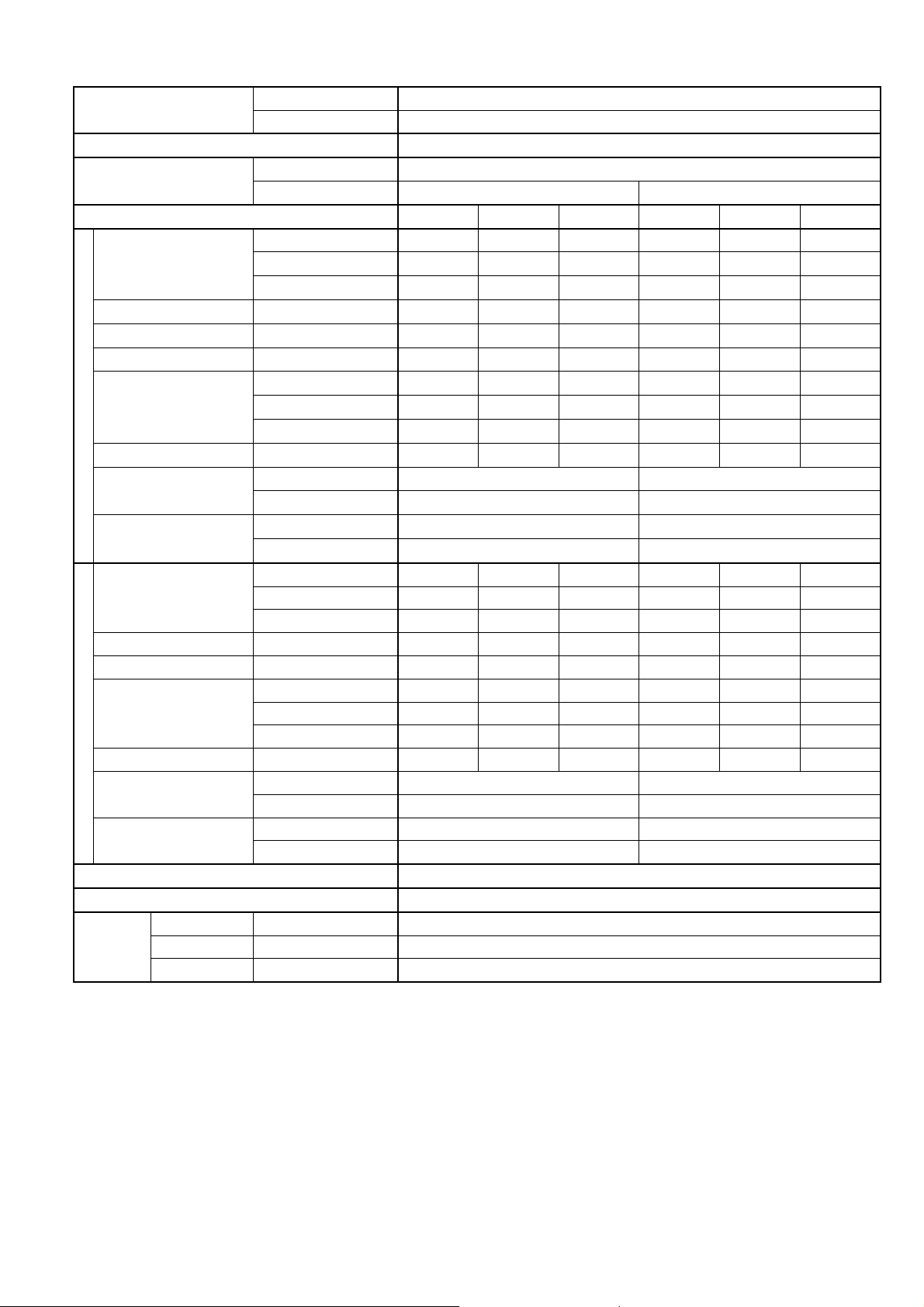
2. Specifications
Model
Performance Test Condition ARI
Power Supply
Min. Mid. Max. Min. Mid. Max.
Capacity
Running Current A – 6.0 – – 5.2 –
Input Power W 250 1.15k 1.32k 250 1.15k 1.32k
Annual Consumption kWh – – – – – –
Cooling
Indoor Noise (H / L / QLo)
Outdoor Noise (H / L / QLo)
Heating
Indoor Noise (H / L / QLo)
Outdoor Noise (H / L / QLo)
Compressor
EER
Power Factor % – 92 – – 96 –
Capacity
Running Current A – 6.9 – – 6.1 –
Input Power W 230 1.36k 1.71k 230 1.36k 1.71k
COP
Power Factor % – 95 – – 97 –
Max Current (A) / Max Input Power (W) 7.80 / 1.71k
Starting Current (A) 6.9
Type Hermetic Motor (Rotary)
Motor Type Brushless (4-poles)
Output Power W 700
Indoor CS-E12RB4UW
Outdoor CU-E12RB4U
Phase, Hz Single, 60
V 208 230
kW 1.20 3.48 3.90 1.20 3.48 3.90
BTU/h 4100 11900 13300 4100 11900 13300
kcal/h (Frig./h) – – – – – –
W/W 4.80 3.03 2.95 4.80 3.03 2.95
BTU/hW 16.40 10.30 10.05 16.40 10.30 10.05
kcal/hW – – – – – –
dB-A 34 / 28 / 25 34 / 28 / 25
Power Level dB 50 / – / – 50 / – / –
dB-A 51 / – / – 51 / – / –
Power Level dB 66 / – / – 66 / – / –
kW 1.20 3.99 4.77 1.20 3.99 4.77
BTU/h 4100 13600 16300 4100 13600 16300
kcal/h (Frig./h) – – – – – –
W/W 5.22 2.93 2.79 5.22 2.93 2.79
BTU/hW 17.80 10.00 9.50 17.80 10.00 9.50
kcal/hW – – – – – –
dB-A 34 / 30 / 27 34 / 30 / 27
Power Level dB 50/ – / – 50 / – / –
dB-A 51 / – / – 51 / – / –
Power Level dB 66 / – / – 66 / – / –
5
Model
Indoor CS-E12RB4UW
Outdoor CU-E12RB4U
Type BACKWARD FAN
Material ABS
Motor Type DC / Transistor (8-poles)
Input Power W –
Output Power W 40
Cool rpm 330
Heat rpm 410
Cool rpm 370
Lo
Heat rpm 460
Cool rpm 460
Heat rpm 540
Cool rpm 560
Hi
Heat rpm 620
Cool rpm 600
Heat rpm 650
Indoor Fan
Speed
QLo
Me
SHi
Type Propeller Fan
Material PP
Motor Type DC (8-poles)
Input Power W –
Outdoor Fan
Output Power W 40
Speed Hi
Cool rpm 830
Heat rpm 820
Min Circuit Ampacity 15.0
Max. Overcurrent Protection 15.0
SEER / HSPF 18.00 / 9.00
Moisture Removal L/h (Pt/h) 1.9 (4.0)
3
/min (ft3/min) 6.7 (240)
3
/min (ft3/min) 7.3 (260)
3
/min (ft3/min) 8.8 (310)
3
/min (ft3/min) 10.5 (370)
3
/min (ft3/min) 11.2 (400)
3
/min (ft3/min) 31.0 (1095) 31.0 (1095)
Indoor
Airflow
Outdoor
Airflow
QLo
Lo
Me
Hi
SHi
Hi
Cool m
Heat m3/min (ft3/min) 7.7 (270)
Cool m
Heat m3/min (ft3/min) 8.5 (300)
Cool m
Heat m3/min (ft3/min) 9.8 (350)
Cool m
Heat m3/min (ft3/min) 11.1 (390)
Cool m
Heat m3/min (ft3/min) 11.6 (410)
Cool m
Heat m3/min (ft3/min) 31.0 (1095) 31.0 (1095)
Control Device Expansion Valve
Refrigeration
Cycle
Refrigerant Oil cm3 FV50S (320)
Refrigerant Type g (oz) R410A, 980 (34.6)
Dimension
Weight
Height (I/D / O/D /
PANEL)
Width (I/D / O/D /
PANEL)
Depth (I/D / O/D /
PANEL)
Net (I/D / O/D /
PANEL)
mm (inch) 260 (10-1/4) / 540 (21-9/32) / 51 (2-1/32)
mm (inch) 575 (22-21/32) / 780 (30-23/32) / 700 (27-9/16)
mm (inch) 575 (22-21/32) / 289 (11-13/32) / 700 (27-9/16)
kg (lb) 18 (40) / 37 (82) / 2.5 (6)
6
Model
Pipe Diameter (Liquid / Gas) mm (inch) 6.35 (1/4) / 12.70 (1/2)
Standard length m (ft) 7.5 (24.6)
Length range (min – max) m (ft) 3 (9.8) ~ 20 (65.6)
I/D & O/D Height different m (ft) 15.0 (49.2)
Piping
Additional Gas Amount g/m (oz/ft) 20 (0.2)
Length for Additional Gas m (ft) 7.5 (24.6)
Drain Hose
Indoor Heat
Exchanger
Outdoor
Heat
Exchanger
Air Filter
Power Supply Cord A Nil
Indoor
Operation
Range
Outdoor
Operation
Range
1. Cooling capacities are based on indoor temperature of 27°C Dry Bulb (80.6°F Dry Bulb), 19.0°C Wet Bulb (66.2°F Wet Bulb) and outdoor air
temperature of 35°C DRY BULB (95°F Dry Bulb), 24°C Wet Bulb (75.2°F Wet Bulb).
2. Heating capacities are based on indoor temperature of 20°C Dry Bulb (68°F Dry Bulb) and outdoor air temperature of 7°C Dry Bulb (44.6°F
Dry Bulb), 6°C Wet Bulb (42.8°F Wet Bulb).
3. Specifications are subjected to change without prior notice for further improvement.
Inner Diameter mm (ft) 30 (0.098)
Length mm (ft) 193 (0.633)
Fin Material Aluminium (Pre Coat)
Fin Type Slit Fin
Row × Stage × FPI 2 × 10 × 18
Size (W × H × L) mm (ft) 1330:1270 × 210 × 25.4 (4.363:4.166 × 0.689 × 0.083)
Fin Material Aluminium (Blue Coated)
Fin Type Corrugated Fin
Row × Stage × FPI 2 × 24 × 17
Size (W × H × L) mm (ft) 36.4 × 504 × 713:684 (0.119 × 1.653 × 2.339:2.244)
Material –
Type –
Power Supply Outdoor
Thermostat Electronic Control
Protection Device Electronic Control
Dry Bulb Wet Bulb
Cooling
Heating
Cooling
Heating
Indoor CS-E12RB4UW
Outdoor CU-E12RB4U
Maximum (°F/°C) 89.6/32 73.4/23
Minimum (°F/°C) 60.8/16 51.8/11
Maximum (°F/°C) 86.0/30 –/–
Minimum (°F/°C) 60.8/16 –/–
Maximum (°F/°C) 114.8/46 78.8/26
Minimum (°F/°C) 0/-17.8 –/–
Maximum (°F/°C) 75.2/24 64.4/18
Minimum (°F/°C) 5.0/-15 3.2/-16
7
Model
Performance Test Condition ARI
Power Supply
Min. Mid. Max. Min. Mid. Max.
Capacity
Running Current A – 9.1 – – 7.7 –
Input Power W 250 1.70k 1.85k 250 1.70k 1.85k
Annual Consumption kWh – – – – – –
Cooling
Indoor Noise (H / L / QLo)
Outdoor Noise (H / L / QLo)
Heating
Indoor Noise (H / L / QLo)
Outdoor Noise (H / L / QLo)
Compressor
EER
Power Factor % – 90 – – 96 –
Capacity
Running Current A – 12.5 – – 10.7 –
Input Power W 270 2.34k 2.50k 270 2.34k 2.50k
COP
Power Factor % – 90 – – 95 –
Max Current (A) / Max Input Power (W) 13.7 / 3.06k
Starting Current (A) 12.5
Type Hermetic Motor (Rotary)
Motor Type Brushless (4-poles)
Output Power W 1.7k
Indoor CS-E18RB4UW
Outdoor CU-E18RB4U
Phase, Hz Single, 60
V 208 230
kW 1.17 5.13 5.47 1.17 5.13 5.47
BTU/h 4000 17500 18700 4000 17500 18700
kcal/h (Frig./h) – – – – – –
W/W 4.68 3.02 2.96 4.68 3.02 2.96
BTU/hW 16.00 10.25 10.10 16.00 10.25 10.10
kcal/hW – – – – – –
dB-A 44 / 30 / 27 44 / 30 / 27
Power Level dB 60 / – / – 60 / – / –
dB-A 51 / – / – 51 / – / –
Power Level dB 65 / – / – 65 / – / –
kW 1.29 5.97 6.15 1.29 5.97 6.15
BTU/h 4400 20400 21000 4400 20400 21000
kcal/h (Frig./h) – – – – – –
W/W 4.78 2.55 2.46 4.78 2.55 2.46
BTU/hW 16.25 8.70 8.40 16.25 8.70 8.40
kcal/hW – – – – – –
dB-A 44 / 31 / 28 44 / 31 / 28
Power Level dB 60 / – / – 60 / – / –
dB-A 52 / – / – 52 / – / –
Power Level dB 66 / – / – 66 / – / –
8
Model
Indoor CS-E18RB4UW
Outdoor CU-E18RB4U
Type BACKWARD FAN
Material ABS
Motor Type DC / Transistor (8-poles)
Input Power W –
Output Power W 40
Cool rpm 360
Heat rpm 430
Cool rpm 390
Lo
Heat rpm 450
Cool rpm 540
Heat rpm 610
Cool rpm 700
Hi
Heat rpm 770
Cool rpm 750
Heat rpm 820
Indoor Fan
Speed
QLo
Me
SHi
Type Propeller Fan
Material PP
Motor Type DC (8-poles)
Input Power W –
Outdoor Fan
Output Power W 60
Speed Hi
Cool rpm 700
Heat rpm 700
Min Circuit Ampacity 20.0
Max. Overcurrent Protection 25.0
SEER / HSPF 17.50 / 8.50
Moisture Removal L/h (Pt/h) 2.9 (6.1)
3
/min (ft3/min) 7.1 (250)
3
/min (ft3/min) 7.6 (270)
3
/min (ft3/min) 10.1 (355)
3
/min (ft3/min) 12.8 (450)
3
/min (ft3/min) 13.6 (480)
3
/min (ft3/min) 54.5 (1925) 54.5 (1925)
Indoor
Airflow
Outdoor
Airflow
QLo
Lo
Me
Hi
SHi
Hi
Cool m
Heat m3/min (ft3/min) 8.3 (290)
Cool m
Heat m3/min (ft3/min) 8.7 (310)
Cool m
Heat m3/min (ft3/min) 11.3 (400)
Cool m
Heat m3/min (ft3/min) 14.0 (495)
Cool m
Heat m3/min (ft3/min) 14.8 (520)
Cool m
Heat m3/min (ft3/min) 54.5 (1925) 54.5 (1925)
Control Device Expansion Valve
Refrigeration
Cycle
Refrigerant Oil cm3 FV50S (800)
Refrigerant Type g (oz) R410A, 1.60k (56.5)
Dimension
Weight
Height (I/D / O/D /
PANEL)
Width (I/D / O/D /
PANEL)
Depth (I/D / O/D /
PANEL)
Net (I/D / O/D) /
PANEL
mm (inch) 260 (10-1/4) / 795 (31-5/16) / 51 (2-1/32)
mm (inch) 575 (22-21/32) / 875 (34-15/32) / 700 (27-9/16)
mm (inch) 575 (22-21/32) / 320 (12-5/8) / 700 (27-9/16)
kg (lb) 18 (40) / 60 (132) / 2.5 (6)
9
Model
Pipe Diameter (Liquid / Gas) mm (inch) 6.35 (1/4) / 12.70 (1/2)
Standard length m (ft) 7.5 (24.6)
Length range (min – max) m (ft) 3 (9.8) ~ 30.5 (100.0)
I/D & O/D Height different m (ft) 15.0 (49.2)
Piping
Additional Gas Amount g/m (oz/ft) 25 (0.3)
Length for Additional Gas m (ft) 10.0 (32.8)
Drain Hose
Indoor Heat
Exchanger
Outdoor
Heat
Exchanger
Air Filter
Power Supply Cord A Nil
Indoor
Operation
Range
Outdoor
Operation
Range
1. Cooling capacities are based on indoor temperature of 27°C Dry Bulb (80.6°F Dry Bulb), 19.0°C Wet Bulb (66.2°F Wet Bulb) and outdoor air
temperature of 35°C DRY BULB (95°F Dry Bulb), 24°C Wet Bulb (75.2°F Wet Bulb).
2. Heating capacities are based on indoor temperature of 20°C Dry Bulb (68°F Dry Bulb) and outdoor air temperature of 7°C Dry Bulb (44.6°F
Dry Bulb), 6°C Wet Bulb (42.8°F Wet Bulb).
3. Specifications are subjected to change without prior notice for further improvement.
Inner Diameter mm (ft) 30 (0.098)
Length mm (ft) 193 (0.633)
Fin Material Aluminium (Pre Coat)
Fin Type Slit Fin
Row × Stage × FPI 2 × 10 × 18
Size (W × H × L) mm (ft) 1330:1270 × 210 × 25.4 (4.363:4.166 × 0.689 × 0.083)
Fin Material Aluminium (Blue Coated)
Fin Type Corrugated Fin
Row × Stage × FPI 2 × 36 × 19
Size (W × H × L) mm (ft) 36.4 × 756 × 868.6:897 (0.119 × 2.480 × 2.849:2.942)
Material –
Type –
Power Supply Outdoor
Thermostat Electronic Control
Protection Device Electronic Control
Dry Bulb Wet Bulb
Cooling
Heating
Cooling
Heating
Indoor CS-E18RB4UW
Outdoor CU-E18RB4U
Maximum (°F/°C) 89.6/32 73.4/23
Minimum (°F/°C) 60.8/16 51.8/11
Maximum (°F/°C) 86.0/30 –/–
Minimum (°F/°C) 60.8/16 –/–
Maximum (°F/°C) 114.8/46 78.8/26
Minimum (°F/°C) 0/-17.8 –/–
Maximum (°F/°C) 75.2/24 64.4/18
Minimum (°F/°C) 5.0/-15 3.2/-16
10

3. Features
Inverter Technology
o Wider output power range
o Energy saving
o Quick Cooling
o Quick Heating
o More precise temperature control
Environment Protection
o Non-ozone depletion substances refrigerant (R410A)
Long Installation Piping
o CS-E12RB4UW, CU-E12RB4U long piping up to 20 meters (65.6 ft)
o CS-E18RB4UW, CU-E18RB4U long piping up to 30.5 meters (100.0 ft)
Easy to use remote control
Quality Improvement
o Random auto restart after power failure for safety restart operation
o Gas leakage protection
o Prevent compressor reverse cycle
o Inner protector to protect compressor
o Noise prevention during soft dry operation
o Blue coated condenser for high resistance to corrosion
Operation Improvement
o Quiet mode to reduce the indoor unit operating sound
o Powerful mode to reach the desired room temperature quickly
o 24-hour timer setting
Serviceability Improvement
o Breakdown Self Diagnosis function
11
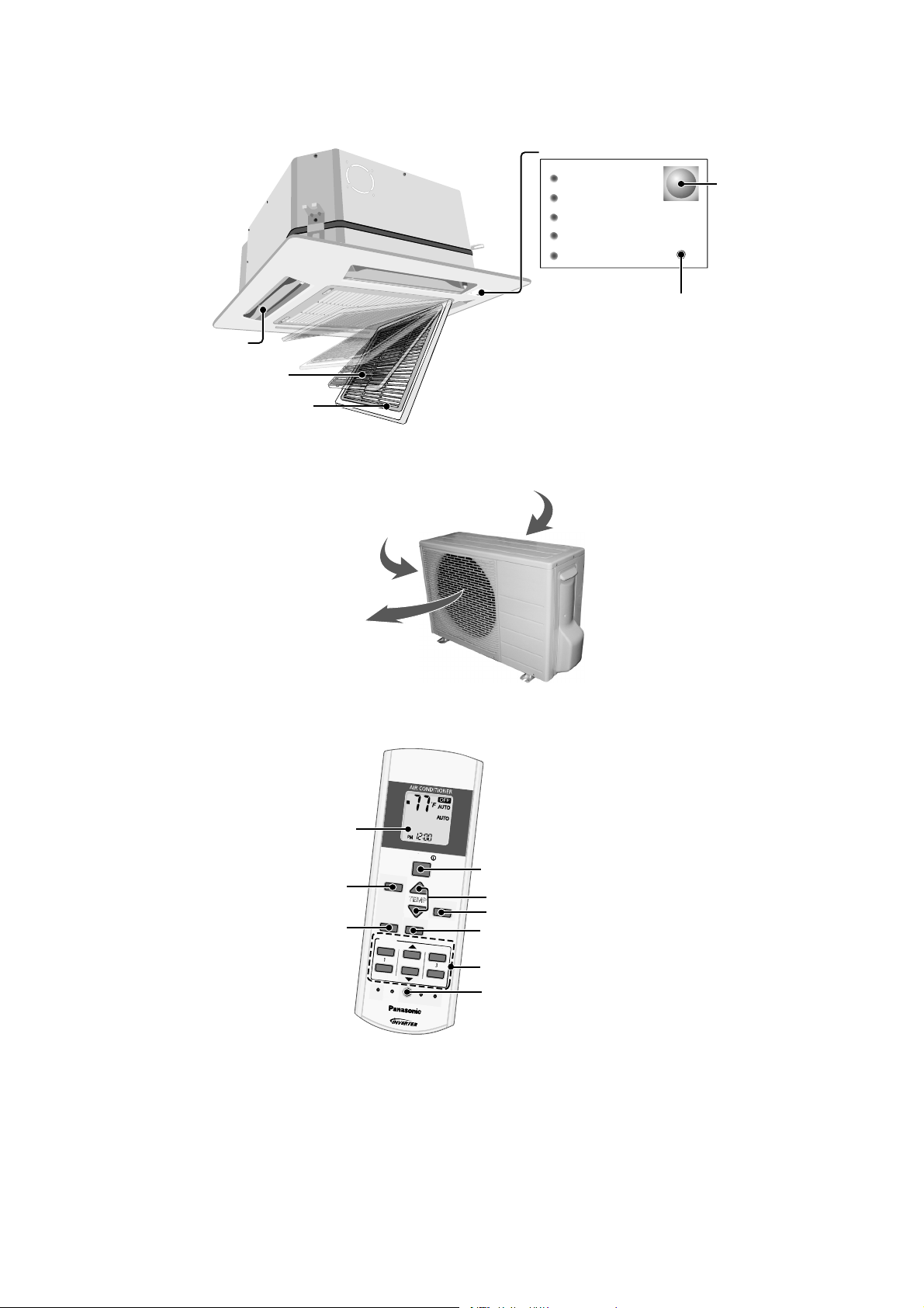
4. Location of Controls and Components
r
A
T
E
M
P
O
O
N
T
I
M
E
R
S
C
C
L
O
N
2
3
C
C
K
4.1 Indoor Unit
E
S
O
L
Airflow direction louver
Air filter
4.2 Outdoor Unit
N
E
P
O
E
S
O
L
C
Intake grille
C
N
E
P
O
Air inlet (side)
A
I
R
T
I
M
P
S
E
O
W
R
W
I
N
E
G
O
R
F
F
/
O
N
Air inlet (rear)
Control Panel
POWER (Green)
TIMER (Orange)
POWERFUL (Orange)
QUIET (Orange)
AIR SWING (Orange)
Receive
AUTO
Auto OFF/ON button
4.3 Remote Control
Operation mode
Powerful/Quiet
ir outlet
LCD display
operation
A
U
T
O
H
E
A
T
C
O
O
L
D
R
Y
F
A
N
M
O
D
E
P
O
W
E
R
F
U
L
/
Q
U
I
E
T
F
A
T
I
M
E
R
O
N
1
O
F
F
F
F
S
E
T
C
H
H
E
E
C
K
C
L
O
F
A
N
S
P
E
E
D
A
I
R
S
W
I
N
G
O
F
F
F
F
/
/
O
N
OFF/ON
T
E
M
P
A
I
R
S
W
N
S
P
E
E
D
S
E
E
T
T
2
3
C
A
A
N
N
C
E
E
L
A
C
R
C
C
K
R
E
S
E
T
Temperature setting
I
N
G
Airflow direction adjustment
Fan speed selection
Timer setting
Clock setting
12
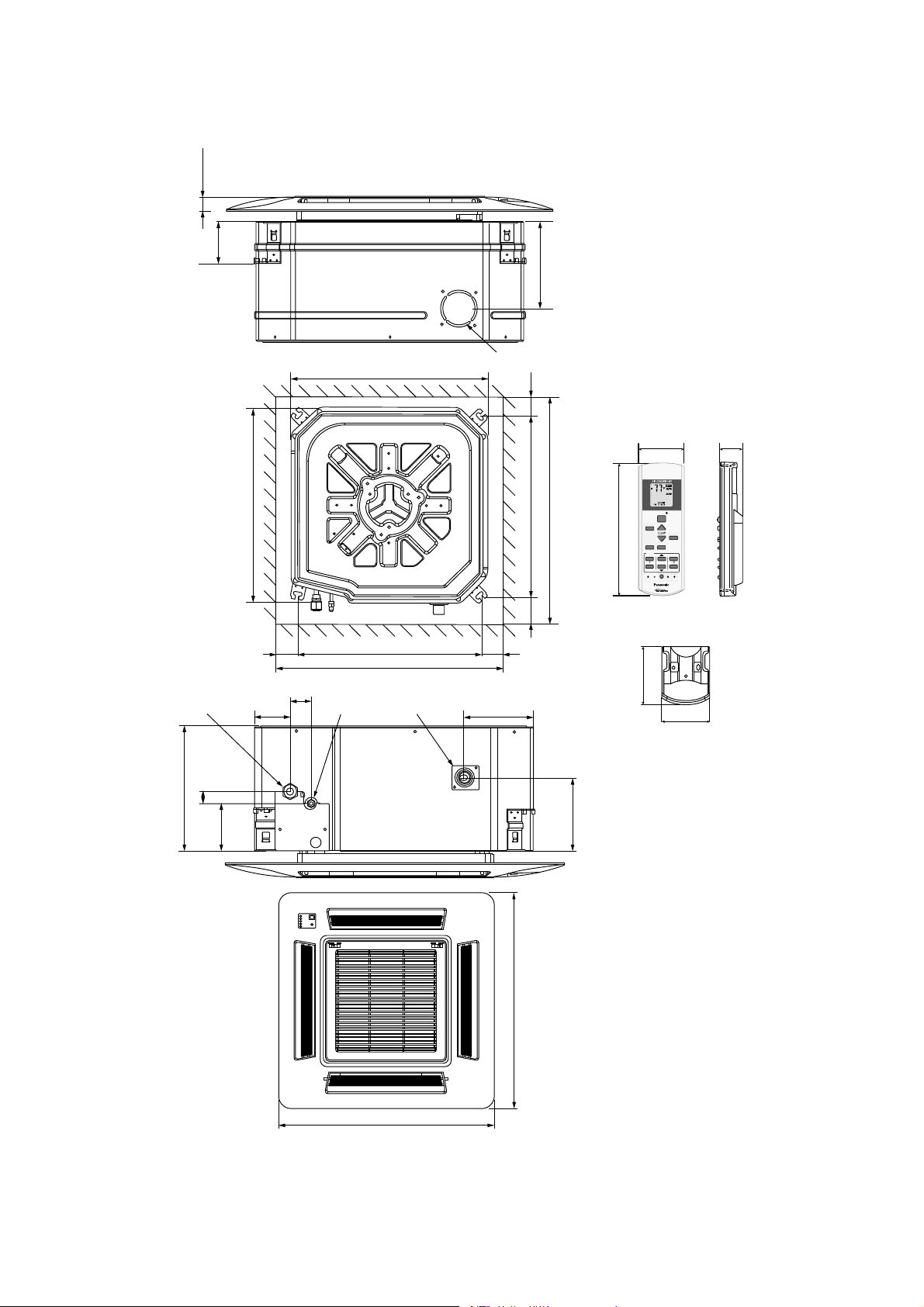
5. Dimensions
TEM
P
O
O
N
TIMER
S
CANCEL
O
N
O
123
CHEC
K
)
5.1 Indoor Unit
30 (1-3/16
90 (3-35/64)
190 (7-31/64)
Gas piping
575 (22-21/32)
73 (2-7/8)
575 (22-21/32)
530 (20-55/64) (Hanging bolt)
650 (25-19/32) (Ceiling opening)
44 (1-47/64)
Liquid piping
Drain pipe
Air Intel
60 (2-23/64)60 (2-23/64)
142 (5-19/32)
60 (2-23/64)60 (2-23/64)
530 (20-55/64) (Hanging bolt)
650 (25-19/32) (Ceiling opening)
<Remote Control>
47 (1-17/32)
FAN
AUTO
SPEED
HEAT
AIR
COOL
SWING
DRY
FAN
OFF/ON
FF/
MODE
TEMP
AIRSWING
POWERFUL/
FAN SP EE D
QUIET
TIMER
SET
123
FF
SETCHECK CLOCK RESET
ET
CANCELONOFF
AC
RC
134 (5-9/32)
22 (55/64)
<Remote Control Holder>
61 (2-13/32)
51 (2-1/64)
260 (10-1/4)
25 (63/64)
100 (3-15/16)
151 (5-15/16)
700 (27-9/16)
700 (27-9/16)
Unit:mm(inch)
13
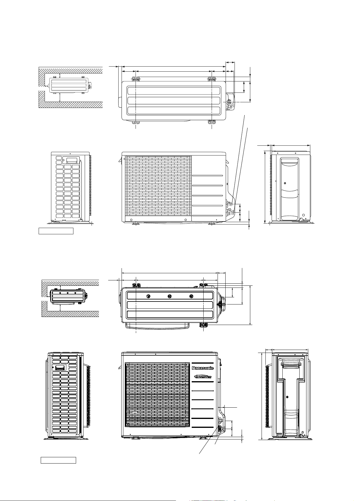
5.2 Outdoor Unit
5.2.1 CU-E12RB4U
Space necessary for
installation
10 cm (3-7/8)
24.4 (1)
<Top View>
(104.7
(4-1/8))
780 (30-23/32)
570 (22-1/2)
104.9
(4-1/8)
67.6
(2-5/8)
60.5
(2-3/8)
34.5
(1-3/8)
10 cm (3-7/8)
100 cm (39-3/8)
Anchor Bolt Pitch
320 (12-5/8) x 570 (22-1/2)
<Side View> <Front View>
Unit : mm (inch)
5.2.2 CU-E18RB4U
Space necessary for
installation
10 cm (3-7/8)
10 cm (3-7/8)
100 cm (39-3/8)
Anchor Bolt Pitch
360.5 (14-3/16) x 613 (24-9/64)
27.5
(1-5/64)
<Top View>
(131
(5-5/32))
875 (34-15/32)
613 (24-1/8)
131
(5-5/32)
70
(2-3/4)
84.8
(3-3/8)
155
(6-1/8)
2-way valve at Liquid side
(High Pressure)
3-way valve at Gas side
(Low Pressure)
11. 5
(1/2)
540 (21-9/32 )
(61.6
(2-3/8))
(18
(3/4))
(69.6
(2-3/4))
38 (1-1/2)
82
(3-7/32)
152
(5-31/32)
360.5 (14-3/16)
<Side View>
289 (11-13/32)
795 (31-5/16)
59
(2-5/16)
<Side View>
320 (12-5/8)
<Side View>
<Front View>
64
(2-17/32)
75
70
(2-61/64)
(25
(2-3/4)
(31/32))
3-way valve at Gas side
(Low Pressure)
Unit : mm (inch)
2-way valve at Liquid side
(High Pressure)
14
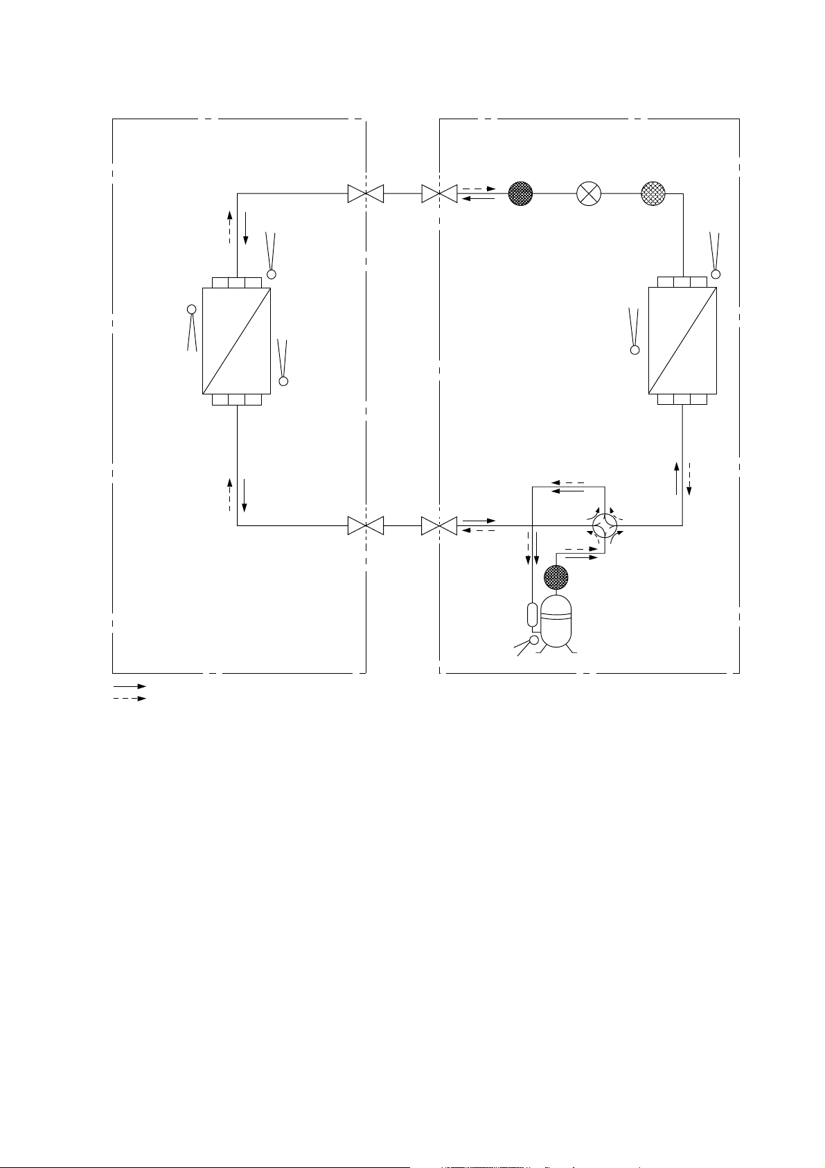
6. Refrigeration Cycle Diagram
DOORO
UTDOO
R
HEA
TIN
G
IN
INTAKE
TEMP.
SENSOR
HEAT EXCHANGER
(EVAPORATOR)
PIPE
TEMP.
SENSOR 1
PIPE
(INLET)
TEMP.
SENSOR 2
LIQUID
SIDE
2-WAY
VALVE
GAS
SIDE
3-WAY
VALVE
MUFFLER/
RECEIVER
EXPANSION
VALV E
TEMP.
SENSOR
HEAT EXCHANGER
(CONDENSER)
MUFFLER
STRAINER
AIR
4-WAY VALVE
PIPE
TEMP.
SENSOR
COMPRESSOR
TEMP.
SENSOR
COMPRESSOR
COOLING
HEATER
15
7. Block Diagram
7.1 CS-E12RB4UW CU-E12RB4U
Q1
3~
MS
COMPRESSOR
FAN MOTOR
FUSE103
M
RY-C
C101
M
SC
EXPANSION
REACTOR
PTC
PTC
PTC1
PTC2
RY-AC1
(OUTDOOR UNIT)(INDOOR UNIT)
VALV E
NTC
TH2
U
RY-HT2
FUSE102
RY-PWR
SINGLE
PHASE
POWER
SUPPLY
FUSE101
1
FAN
MOTOR
FUSE
SC
PUMP
DRAIN
VALV E
4-WAYS
HEATER
CT102
NOISE FILTER
2
3
16
7.2 CS-E18RB4UW CU-E18RB4U
3~
MS
V
U
W
NTC
PTC1
TH2
P
N
M
FUSE1
DB3
Q1
DB1
REACTOR
CT400
PTC2
FUSE2
RY-PWR1
RY-C
VALV E
4-WAYS
RY-HOT
CR3
HEATER
SC
TH1
NTC
DB2
NOISE FILTER
FUSE 3
(OUTDOOR UNIT)
L
N
(INDOOR UNIT)
SINGLE PHASE
POWER SUPPLY
123
FUSE
FAN
MOTOR
SC
PUMP
DRAIN
17
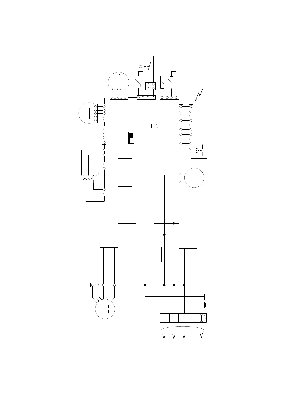
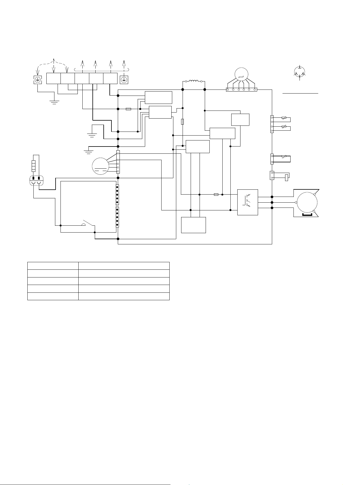
8. Wiring Connection Diagram
TRANS
F
E
TOOU
T
U
NIT
T
8.1 Indoor Unit
MOTOR
M
1
Y
P
R
O
BR
1
POYRBR
OR
MO
R
ORM
51
M
BL
BL
YYR
R
(WHT)
CN-STM1
(YLW)
CN-STM2
15
5
(WHT)
CN-CNT
1
T-BL K2
T-BLK1
2
1
(YLW)
CN-T2
1
CN-T1
RECTIFICATION
2
(WHT)
RECTIFICATION
5
5
HIGH STATIC
CIRCUIT
CIRCUIT
INTAKE AIR TEMPERATURE SENSOR
PRESSURE
(FAN)
FLOAT
SWITCH
INDOOR PIPE
TEMPERATURE
SENSOR 2
INDOOR PIPE
TEMPERATURE
SENSOR 1
BL
BL
t˚
BLBLBL
4
CN-TH1
SW02
DRAIN PUMP
TEST RUN
t˚
BL
(WHT)
1
CN-DRMTR1
110
CN-DISP(WHT)
(BLU)
13
BR
BR R R B B WYYW
M
REMOTE CONTROLLER
10
CN-DISP(WHT)
ELECTRONIC
CONTROLLER(DISPLAY)
1
AUTO SW
~
1
DRAIN PUMP
t˚
P
P
BL
BL
4
1
(BLU)
CN-TH2
SW01
ELECTRONIC CONTROLLER (MAIN)
CN-FM
765
Y
B
MOTOR
(WHT)
W
BL
M
CIRCUIT
RECTIFICATION
4
1
R
REMARKS
B:BLUE P:PINK
BR:BROWN O:ORANGE
BL:BLACK Y:YELLOW
CIRCUIT
NOISE FILTER
FUSE01
T3.15A L250V
G01(GRN)
G
W:WHITE GR:GRAY
R:RED G:GREEN
Y/G:YELLOW/GREEN
AC01(BLK)
AC02(WHT)
W
BL
1
TERMINAL
BOARD
CIRCUIT
COMMUNICATION
AC03(RED)
R
Y/G
2
3
DOOR
18
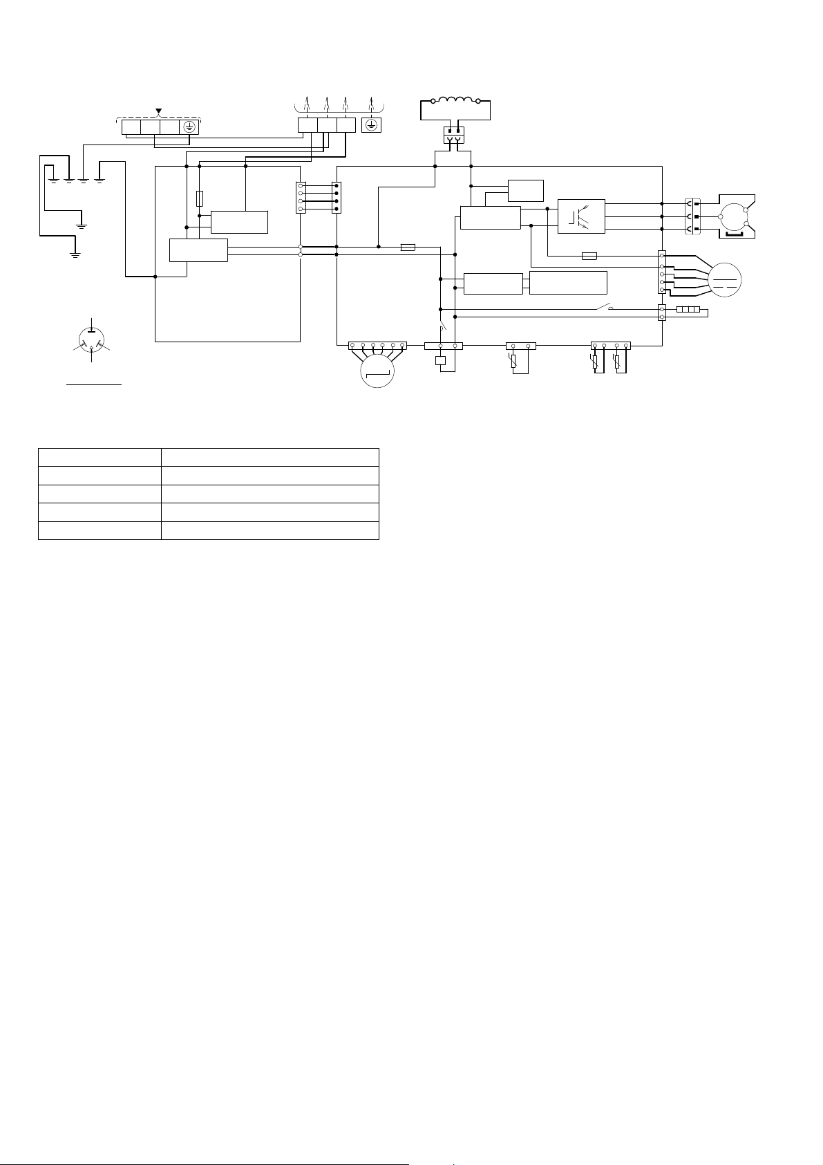
8.2 Outdoor Unit
R
B
B
W
R
Y
B
O
Y
OWE
8.2.1 CU-E12RB4U
EMARKS;
LACK; (BLK)
LUE; (BLU)
ED; (RED)
ELLOW; (YLW)
GRAY; (GRY)
GREEN; (GRN)
ROWN; (BRW)
RANGE; (ORG)
ELLOW/GREEN; (YLW/GRN)
Resistance of Compressor Windings
Note: Resistance at 20°C of ambient temperature.
RSUPPLY
P
YLW/GRN
HITE; (WHT)
HEATER
ORG
L1
L2
BLK
ORG
ELECTRONIC
CONTROLLER
HT2(ORG)
TO INDOOR UNIT
1
(
)
BLACK
(WHITE)
BLK
MOTOR
ACL(BRW)
WHT
GRN
FAN
RY-HT2
2
WHT
GRN
M
CN-HT1
CN-HT2
BRW
3
(RED)
RED
DATA (
AC-BLK
(BLK)
FUSE101
20A 250V
AC–WHT
(WHT)
FG1 (GRN)
LJP101 (GRN)
1
4
CN-DCFM
7
HT2 (ORG)
1
CN4
5
1
CN5
5
ACL(BRW)
TERMINAL BOARD
)
RED
COMMUNICATION
CIRCUIT
NOISE FILTER
(WHT)
CIRCUIT
GRY
REACTOR
RAT2
(GRY)
FUSE102
T3.15A L250V
RECTIFICATION
CIRCUIT
SWITCHING
POWER SUPPLY
CIRCUIT
ELECTRO-MAGNETIC
COIL (EXPANSION VALVE)
GRY
RAT1
(GRY)
FUSE103
T3.15A L250V
1
RECTIFICATION
CIRCUIT
CIRCUIT
M
CN–STM
(WHT)
PFC
Q1
P
N
6
CN–TH
(WHT)
CN–TANK
(WHT)
CN–HOT
(WHT)
(
U
(
V
(
W
YELLOW (YLW)
BLUE (BLU)
(TRADEMARK)
COMPRESSOR TERMINAL
THE PARENTHESIZED LETTERS IS
INDICATED ON TERMINAL COVER
AIR TEMP. SENSOR
(THERMISTOR)
1
t°
2
3
t°
4
PIPING TEMP. SENSOR
(THERMISTOR)
COMPRESSOR TEMP. SENSOR
(THERMISTOR)
1
t°
3
YLW
RED
BLU
YLW
1
2
)
)
)
YLW
RED
BLU
YLW
ELECTRO-MAGNETIC
COIL (4-WAY VALVE)
RED (RED)
MS
~
3
COMPRESSOR
ELECTRONIC CONTROLLER
MODEL CU-E12RB4U
CONNECTION 5RS102XHA21
U-V 1.741 Ω
U-W 1.711 Ω
V-W 1.765 Ω
19
8.2.2 CU-E18RB4U
TOIN
DOORUNIT
R
(EX
PAN
SINGLE PHASE POWER SUPPLY
AC 208-230V 60Hz
GRN
RED
(RED)
L1
YLW/GRN
GRN
YLW/GRN
YELLOW (YLW)
BLUE
(BLU)
(TRADEMARK)
COMP. TERM INAL
THE PARENTHESIZED LETTERS IS
INDICATED ON TERMINAL COVER
L2
(WHITE)
FG1 (GREEN)
TERMINAL
BOARD
WHT
BLK
WHT
ACL1
ACN1
(BLACK)
FUSE3
(25A, 250V)
COMMUNICATION
NOISE FILTER
CIRCUIT
ELECTRONIC CONTROLLER
(NOISE FILTER)
REMARKS
BLU : BLUE BRW: BROWN
ORG: ORANGE BLK : BLACK
YLW: YELLOW WHT : WHITE
GRY : GRAY RED : RED
GRN: GREEN
YLW/GRN : YELLOW/GREEN
BLK
CIRCUIT
COM3
(RED)
TERMINAL
BOARD
CN-COM
(YELLOW)
CN-BLK
(BLACK)
CN-WHT
(WHITE)
123
RED
WHT
1
WHT
WHT
WHT
4
BLK
WHT
ELECTRO-MAGNETIC COIL
1
CN-COM
(YELLOW)
4
AC-BLK
(BLACK)
AC-WHT
(WHITE)
6
(T3.15A L250V)
CN-EV
(WHITE)
M
SIONVALVE)
Resistance of Compressor Windings
MODEL CU-E18RB4U
CONNECTION 5KD240XAF21
U-V 0.720 Ω
U-W 0.726 Ω
V-W 0.708 Ω
Note: Resistance at 20°C of ambient temperature.
GRY
GRY
L2-1
(GRAY)
FUSE2
1
1
ELECTRO-MAGNETIC
COIL (4-WAY VALVE)
REACTOR
2
2
CN-HOT
(BLUE)
RY-HOT
BLK
1
1
BLK
L2-O
(BLACK)
RECTIFICATION
CIRCUIT
RECTIFICATION
CIRCUIT
CN-TANK
3
t°
COMP. TEMP.
SENSOR
(THERMISTOR)
PFC
CIRCUIT
SWITCHING POWER
(WHITE)
13
ELECTRONIC CONTROLLER (MAIN)
Q10
P
N
FUSE1
(T3.15A L250V)
SUPPLY CIRCUIT
RY-HT
PIPING TEMP.
SENSOR
(THERMISTOR)
4
t°
U
V
W
CN-TH1
(WHITE)
t°
(RED) U
(BLUE) V
(YELLOW) W
(WHITE)
CN-HT
(BLACK)
OUTDOOR AIR
TEMP. SENSOR
(THERMISTOR)
CN-FM
1
RED
BLU
YLW YLW
RED
1
4
BLK
WHT
BLU
7
YLW
HEATER
1
3
33
1
RED
BLU
1
FAN MOTOR
COMPRESSO
MS
~
3
M
20
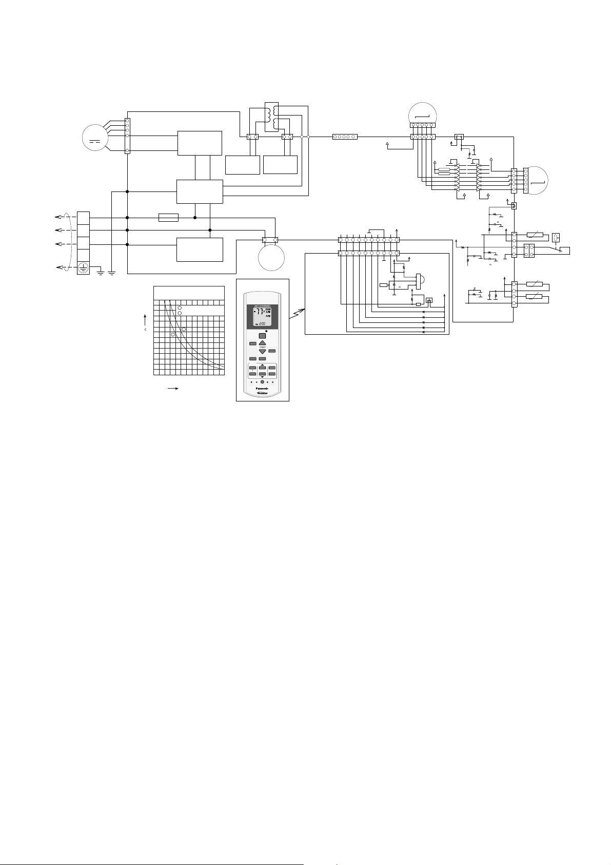
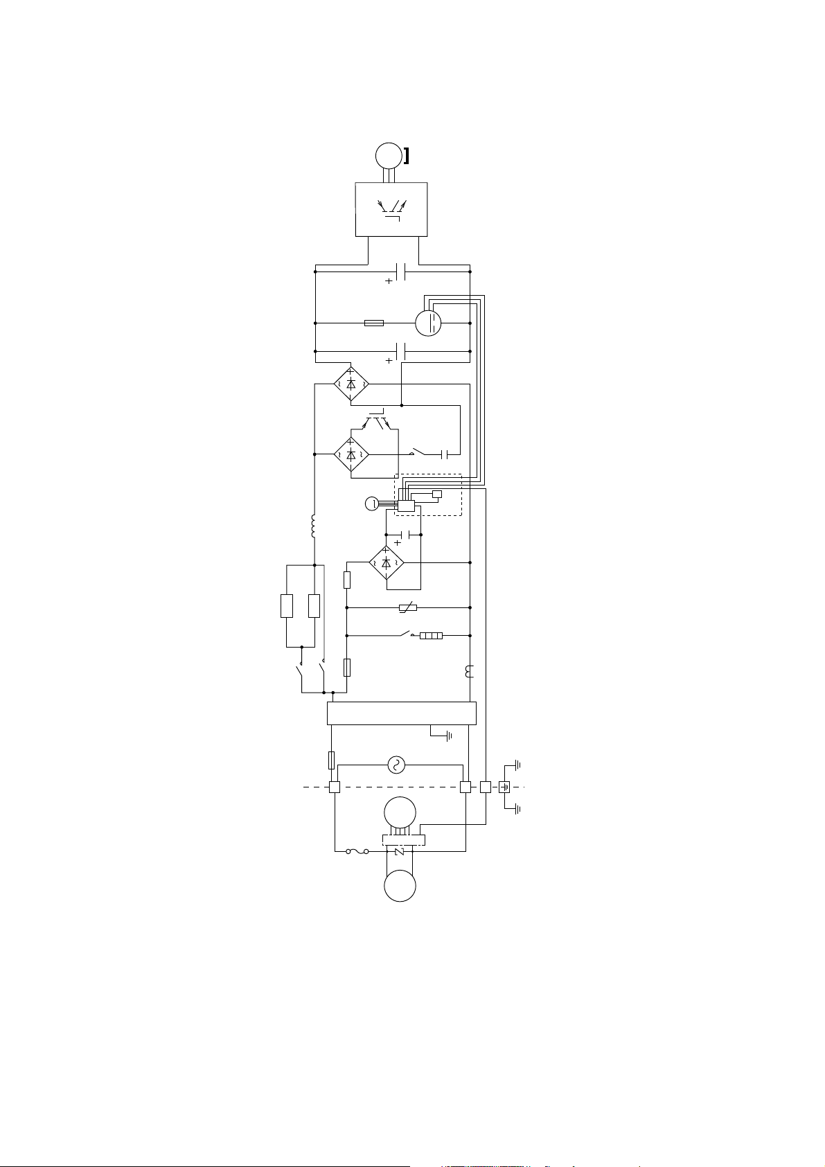
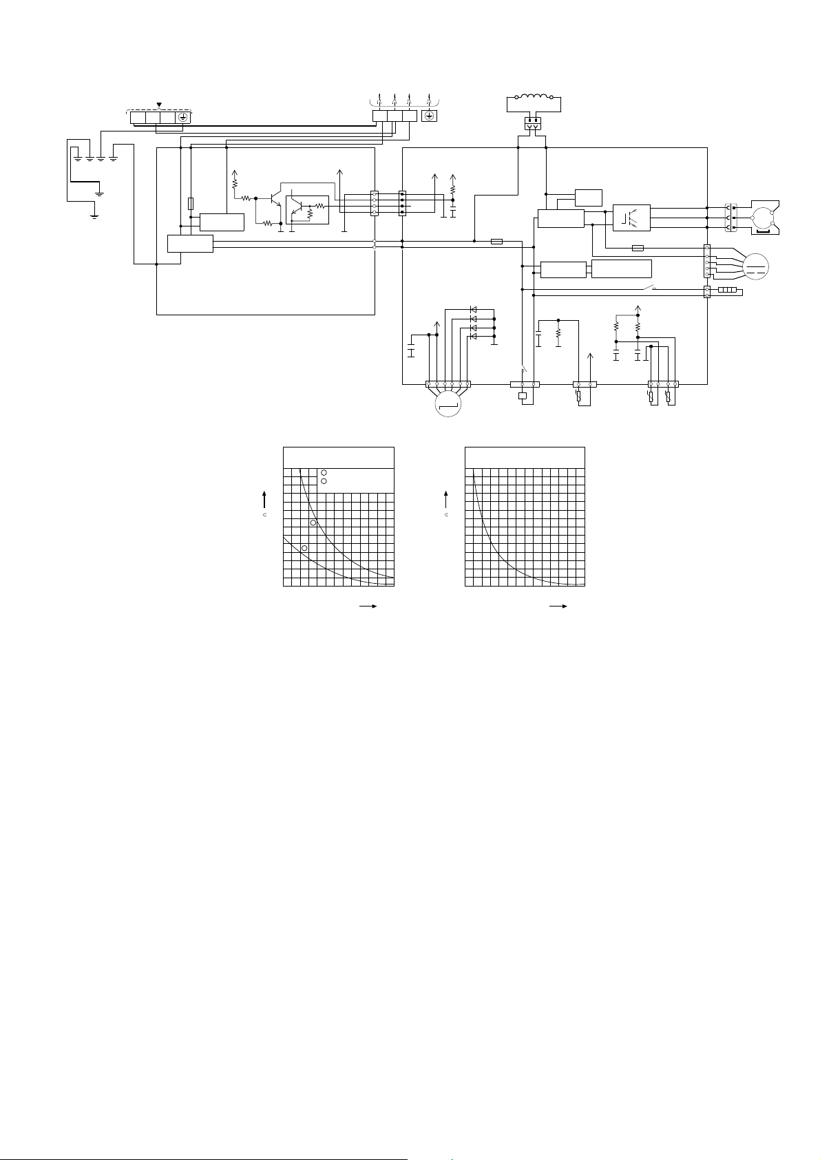
9. Electronic Circuit Diagram
RANSFORME
R
UTDOORUN
M
R
TEMP
O
O
N
TIMER
S
CANCEL
O
N
O
123
CHEC
K
9.1 Indoor Unit
Y
MOTOR
B
W
BL
M
R
G
TERMINAL
BOARD
1
IT
2
3
TO O
BL
W
R
Y/G
ELECTRONIC CONTROLLER (MAIN)
7
CN-FM
6
(WHT)
5
4
1
G01(GRN)
FUSE01
T3.15A L250V
AC01(BLK)
AC02(WHT)
AC03(RED)
Sensor (Thermistor)
Characteristics
70
1
60
2
50
40
2
30
Resistance (k )
20
10
0
-10
(14)0(32)10(50)
RECTIFICATION
CIRCUIT
NOISE FILTER
CIRCUIT
COMMUNICATION
CIRCUIT
Pipe temp.Sensor
Intake Air Temp. Sensor
1
20
(68)30(86)40(104)50(122)
Temperature°C (°F)
R
CN-T1
1
(WHT)
RECTIFICATION
CIRCUIT
REMOTE CONTROLLER
AUTO
HEAT
COOL
DRY
FAN
MODE
POWERFUL/
TIMER
SET CHECKCLOCK R ESET
T
2
DRAIN PUMP
OFF/ON
FF/
TEMP
QUIET
FANSPEED
ON
123
FF
OFF
CN-T2
(YLW)
RECTIFICATION
M
1
~
AIRSWING
SET
CANCEL
AC
CIRCUIT
13
FAN
SPEED
AIR
SWING
ET
RC
BL
BL
YYR
1
2
CN-DRMTR1
(BLU)
CN-CNT
T-BL K1
T-BL K2
CN-DISP(WHT)
ELECTRONIC
CONTROLLER
(DISPLAY)
1
(WHT)
BR
BR R R B B WYYW
1
OTO
M
51
HIGH STATIC
PRESSURE
POYRBR
(FAN)
SW01
Auto
1
Power
Timer
Powerful
Quiet
Air Swing
5V
C30
R13
12V
12V
8
16
1
SSR02
15
2
SSR01
14
3
13
4
12
5
11
6
10
7
12V
9
5V
R56
10k
R57
1k
5V
SW201
3
CN-STM1
8
(WHT)
16
1
2
3
4
5
6
7
IC05IC07
C29
1000p
C04
1
R31
20.0k
1
BR
15
14
13
12
11
10
12V
9
R55
10k
C31
0.01
R54
1k
R33
15.0k
C05
1
C43
R75
CN-TH1
1
R
O
M
Y
P
5
5
5V
DRAIN PUMP
TEST RUN
SW02
INTAKE AIR TEMPERATURESENSOR
(15k 3950)
5V
BL
4
BL
t˚
P
BL
P
BL
1
CN-TH2
(BLU)
5V
4
BL
BL
t˚
BL
BL
t˚
1
(WHT)
MOTOR
FLOAT
SWITCH
INDOOR PIPE
TEMPERATURE
SENSOR 2
(20k 3950)
INDOOR PIPE
TEMPERATURE
SENSOR 1
(20k 3950)
CN-STM2
12V
R202
C202
(YLW)
5V
110
10
5V
R203
10k
47
+
C201
47 F
(NHG)
15
CN-DISP(WHT)
5V
IC201
Vout 1
Vout 2
GND 3
5V
R201
1k
BZ201
BZ
D201
D202
D203
D204
D205
5
21
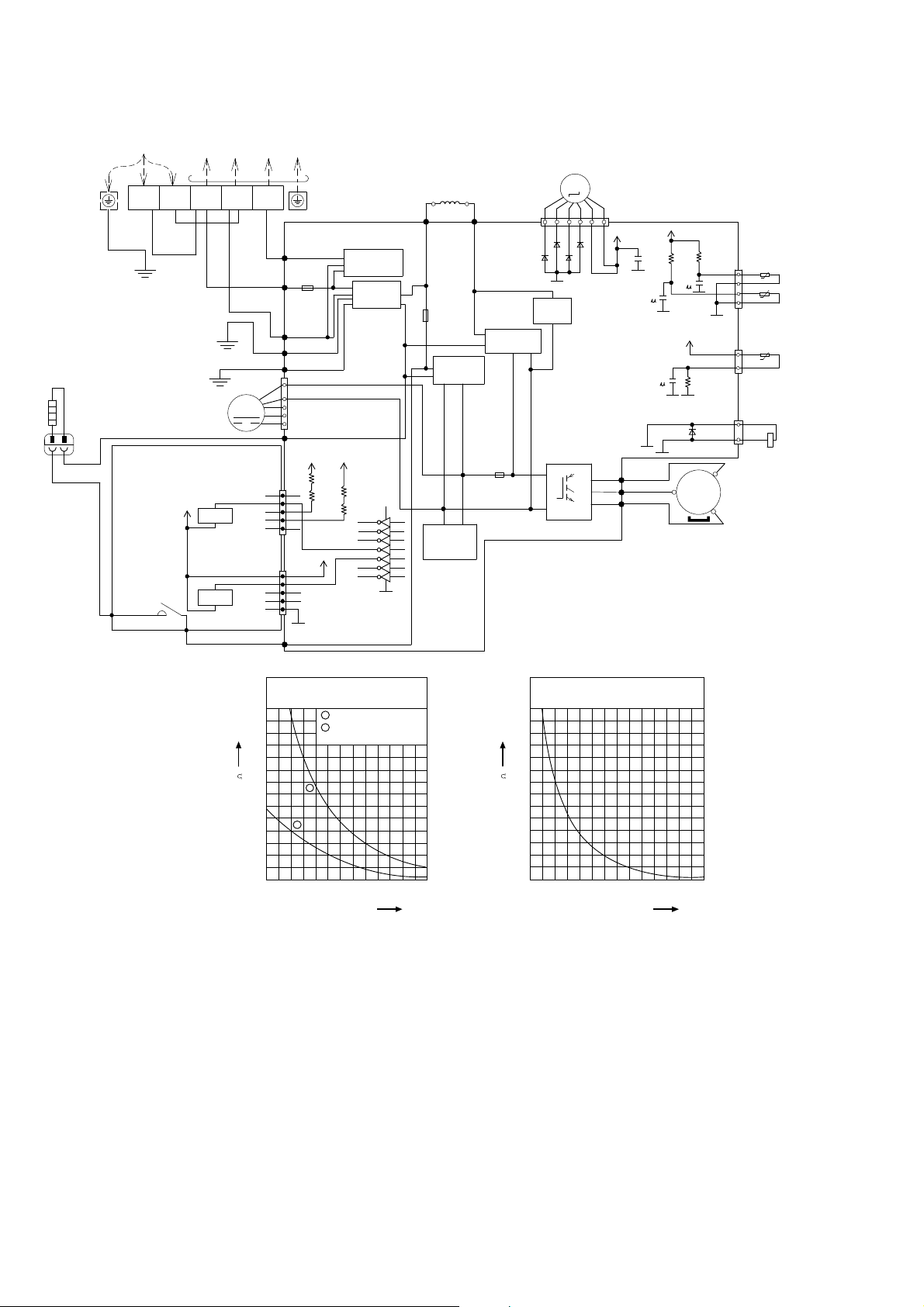
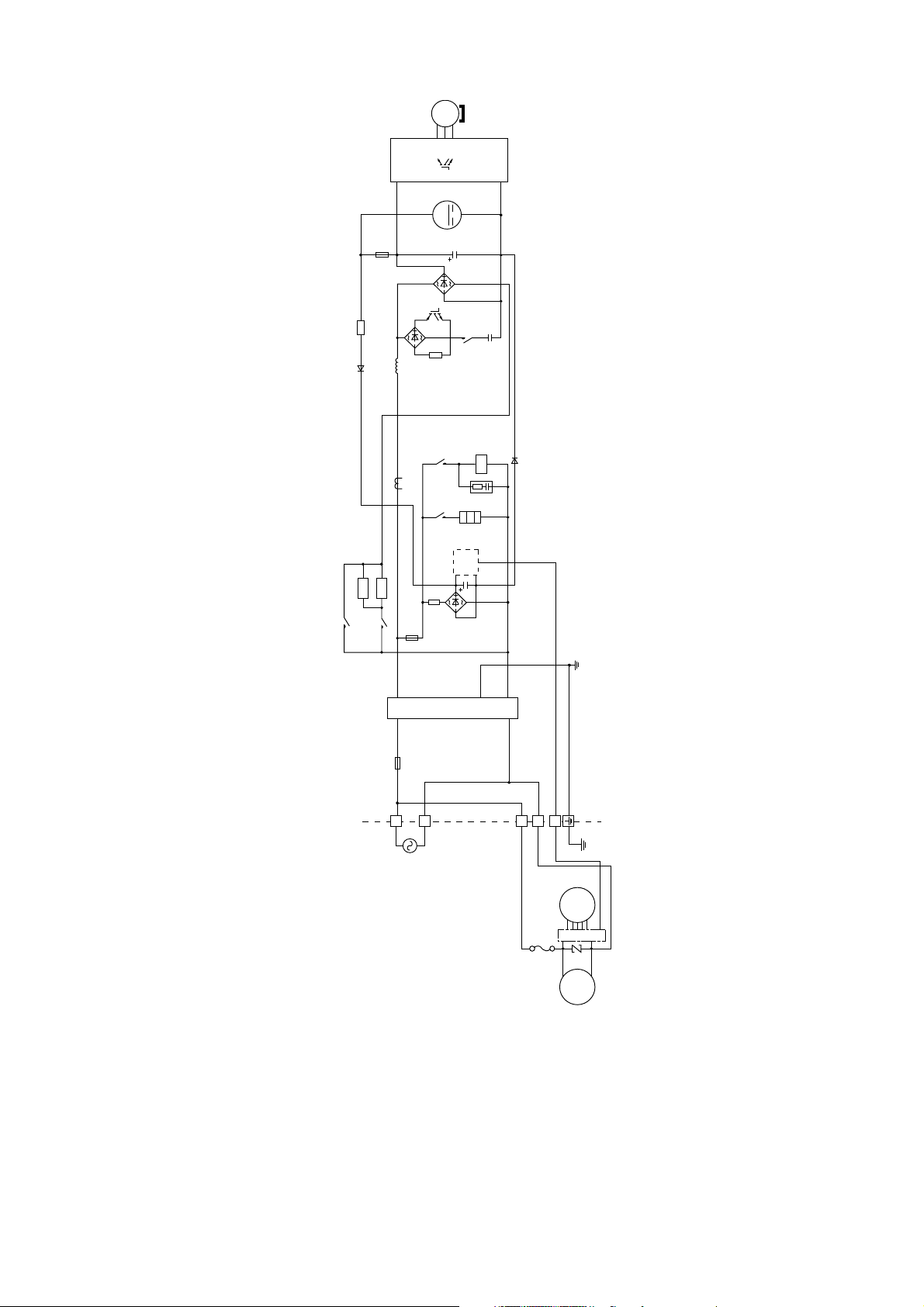
9.2 Outdoor Unit
P
OWERSUPPL
Y
9.2.1 CU-E12RB4U
TO INDOOR UNIT
1
(
BLACK
BLK
FAN
MOTOR
BRW
GRN
)
(WHITE)
2
WHT
WHT
M
RY-HT1
RY-HT2
(RED)
GRN
CN-HT1
CN-HT2
HEATER
ORG
L1
YLW/GRN
ORG
ELECTRONIC
CONTROLLER
HT2(ORG)
ACL(BRW)
L2
BLK
13V
RY-HT2
3
RED
1
2
3
4
5
1
2
3
4
5
AC–WHT
(WHT)
CN4
CN5
TERMINAL BOARD
DATA (
RED
AC-BLK
(BLK)
FUSE101
20A 250V
FG1 (GRN)
LJP101 (GRN)
1
4
CN-DCFM
(WHT)
7
HT2 (ORG)
5V
R129
1k
1
R118
2
3
4
5
13_1V
1
2
3
4
5
ACL(BRW)
)
COMMUNICATION
NOISE FILTER
5V
R130
1k
R116
CIRCUIT
CIRCUIT
16
15
14
13
12
11
10
ELECTRO-MAGNETIC
COIL (EXPANSION VALVE)
REACTOR
FUSE102
T3.15A L250V
RECTIFICATION
CIRCUIT
SWITCHING
CIRCUIT
GRY
CN–STM
RAT1
(WHT)
(GRY)
RECTIFICATION
CIRCUIT
FUSE103
T3.15A L250V
ELECTRONIC CONTROLLER
GRY
RAT2
(GRY)
9
1
IC12
2
IC12
3
IC12
POWER SUPPLY
4
IC12
5
IC12
6
IC12
7
IC12
8
M
123456
D28
D26
D27
D29
PFC
CIRCUIT
Q1
P
U
V
W
N
(
RED
(
(
BLU
YLW
13V
)
)
)
5V
CN–TH
R12
R11
C80
RED
BLU
YLW
15.0k
15.8k
C7
1
C6
1
5V
C3
R1
1
4.99k
D19
MS
3
AIR TEMP. SENSOR
(WHT)
(THERMISTOR)
1
2
3
4
CN–TANK
COMPRESSOR TEMP. SENSOR
(WHT)
(THERMISTOR)
1
3
CN–HOT
(WHT)
1
2
~
t°
t°
PIPING TEMP. SENSOR
(THERMISTOR)
t°
YLW
ELECTRO-MAGNETIC
COIL (4-WAY VALVE)
YLW
COMPRESSOR
70
60
50
40
30
Resistance (k )
20
10
0
Sensor (Thermistor)
Characteristics
1
Outdoor Air Sensor
2
Outdoor Heat Exchanger
Sensor
1
2
-10
(14)0(32)10(50)
Temperature °C (°F)
20
(68)30(86)40(104)50(122)
Compressor Temp. Sensor
(Thermistor) Characteristics
70
60
50
40
30
Resistance (k )
20
10
0
20
(68)40(104)60(140)
80
100
(176)
Temperature °C (°F)
(212)
120
(248)
140
(284)
22
9.2.2 CU-E18RB4U
T
OINDO
ORU
NIT
SINGLE PHASE POWER SUPPLY
AC 208-230V 60Hz
GRN
YLW/GRN
YLW/GRN
GRN
L1
L2
WHT
ACN1
(WHITE)
NOISE FILTER
FG1 (GREEN)
CIRCUIT
TERMINAL
BOARD
BLK
WHT
BLK
ACL1
COM3
(BLACK)
(RED)
5V
R425
R426
FUSE3
(25A, 250V)
COMMUNICATION
CIRCUIT
ELECTRONIC CONTROLLER
(NOISE FILTER)
Q28
b
R427
Resistance (k )
c
c
e
e
G1
G1
Sensor (Thermistor)
70
60
50
40
30
2
20
10
0
-10
(14)0(32)10(50)
Temperature °C (°F)
5V
Q25
4.7k
b
10k
Characteristics
1
OutdoorAir Sensor
2
Outdoor Heat Ex ch an ger
Sensor
1
(68)30(86)40(104)50(122)
TERMINAL
BOARD
CN-COM
(YELLOW)
G1
CN-WHT
(WHITE)
20
CN-BLK
(BLACK)
123
1
WHT
WHT
WHT
WHT
4
BLK
WHT
RED
5
V
CN-COM
(YELLOW)
1
4
G5
AC-BLK
(BLACK)
AC-WHT
(WHITE)
13V
*C84
G2
6
ELECTRO-MAGNETIC COIL
(EXPANSION VALVE)
GRY
5
V
G5
M
Resistance (k )
(GRAY)
R159
C63
FUSE2
(T3.15A L250V)
*D33
*D34
*D35
*D36
G2
CN-EV
(WHITE)
1
Compressor Temp.Sensor
(Thermistor) Characteristics
70
60
50
40
30
20
10
0
20
(68)40(104)60(140)
Temperature °C (°F)
REACTOR
2
GRY
L2-1
CN-HOT
(BLUE)
RY-HOT
1
ELECTRO-MAGNETIC
COIL (4-WAY VALVE)
80
100
(176)
(212)
BLK
112
BLK
L2-O
(BLACK)
RECTIFICATION
CIRCUIT
RECTIFICATION
CIRCUIT
R410
C49
4.99k
1µ
G5G5
3
t°
COMP. TEMP.
SENSOR
(THERMISTOR)
(50K 3950)
120
140
(248)
(284)
PFC
CIRCUIT
SWITCHING POWER
SUPPLY CIRCUIT
R101
15.8k
C461µC45
V
5
CN-TANK
(WHITE)
13
ELECTRONIC CONTROLLER (MAIN)
Q10
P
N
FUSE1
(T3.15A L250V)
RY-HT
5
V
R100
15.8k
1µ
G5 G5G5
PIPING TEMP.
SENSOR
(THERMISTOR)
(4.96K 3800)
U
V
W
4
t°
(BLUE) V
(YELLOW) W
(BLACK)
1
t°
OUTDOOR AIR
TEMP. SENSOR
(THERMISTOR)
(15K 3950)
(RED) U
(WHITE)
CN-HT
CN-FM
CN-TH1
(WHITE)
RED
BLU
YLW YLW
RED
1
4
BLK
WHT
BLU
7
YLW
HEATER
1
3
33
1
RED
BLU
1
FAN MOTOR
COMPRESSOR
MS
~
3
M
23
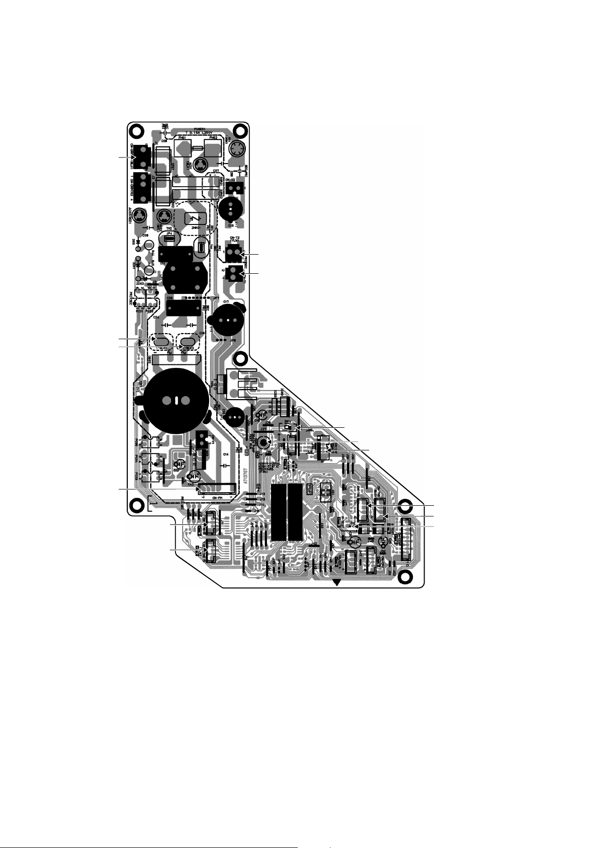
10. Printed Circuit Board
10.1 Indoor Unit
10.1.1 Main Printed Circuit Board
CN-DRMTR1
CN-T2
CN-T1
T-BLK1
T-BLK2
CN-FM
CN-STM1
CN-STM2
SW01
SW02
CN-CNT
CN-TH1
CN-TH2
JP3
(Random Auto Restart
enable/disable)
24
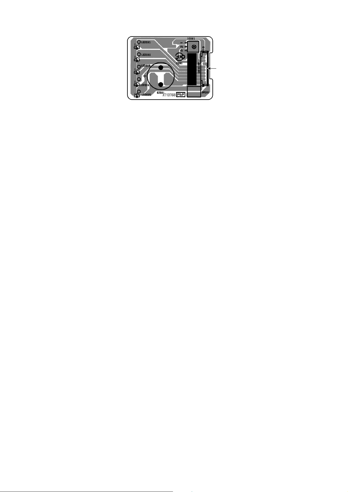
10.1.2 Display Printed Circuit Board
CN-DISP
25
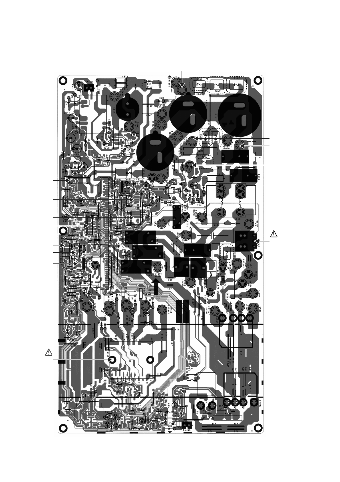
10.2 Outdoor Unit
FG1
10.2.1 Main Printed Circuit Board
10.2.1.1 CU-E12RB4U
CN-DCFM
AC-BLK
AC-WHT
DATA
CN5
CN4
CN-STM
CN-TANK
CN-TH
CN-HOT
POWER
TRANSISTOR
(IPM)
CURRENT
TRANSFORMER
(CT)
26

10.2.1.2 CU-E18RB4U
CN-EV
CN-TH1
CN-TANK
CN-ACFM
CN-HT
CN-HOT
AC-BLK
AC-WHT
CURRENT
TRANSFORMER
(CT)
CN-COM
POWER
TRANSISTOR
(IPM)
27
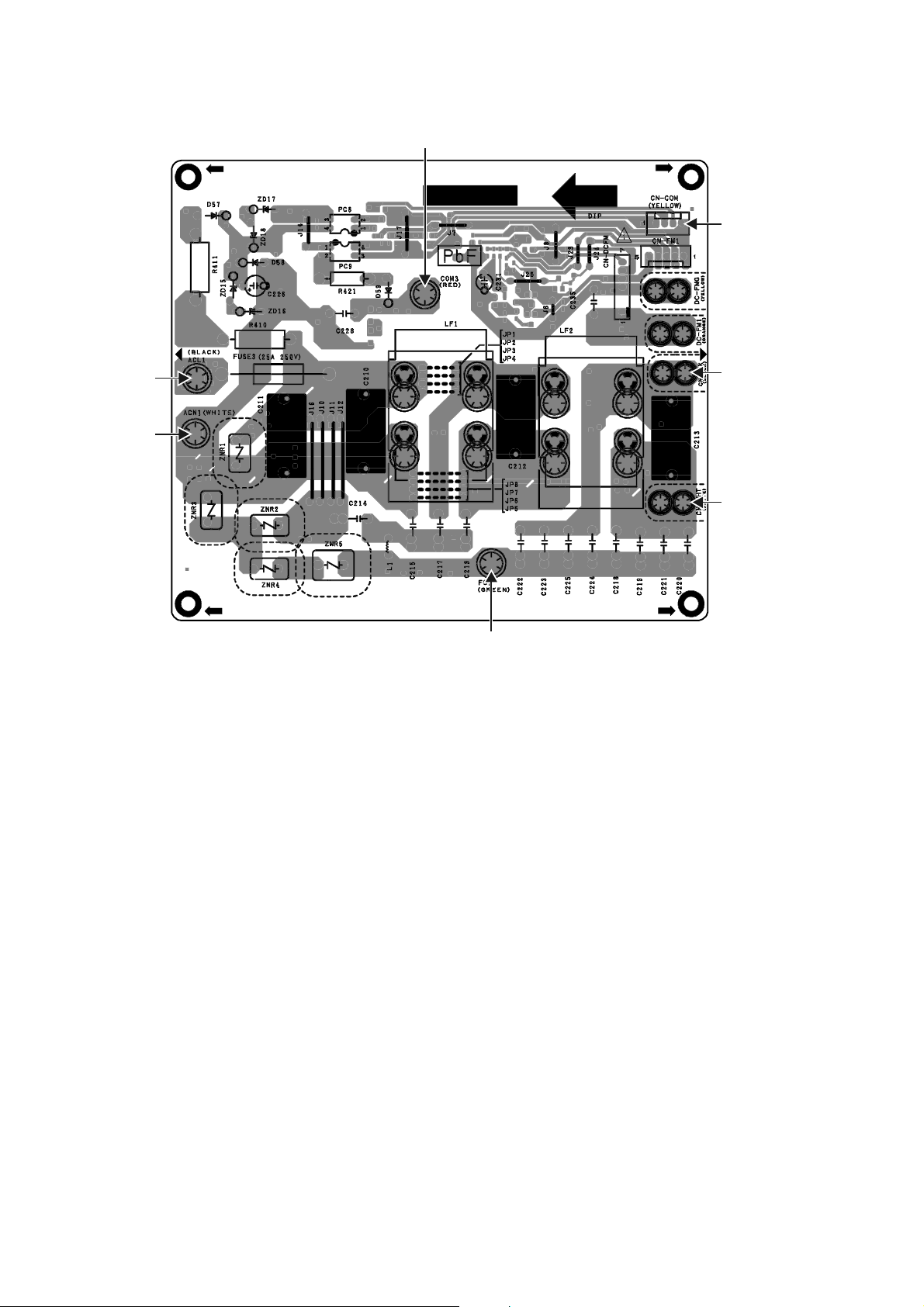
10.2.2 Noise Filter Printed Circuit Board
FG1
C
10.2.2.1 CU-E18RB4U
OM3
CN-COM
ACL1
ACN1
CN-BLK
CN-WHT
28
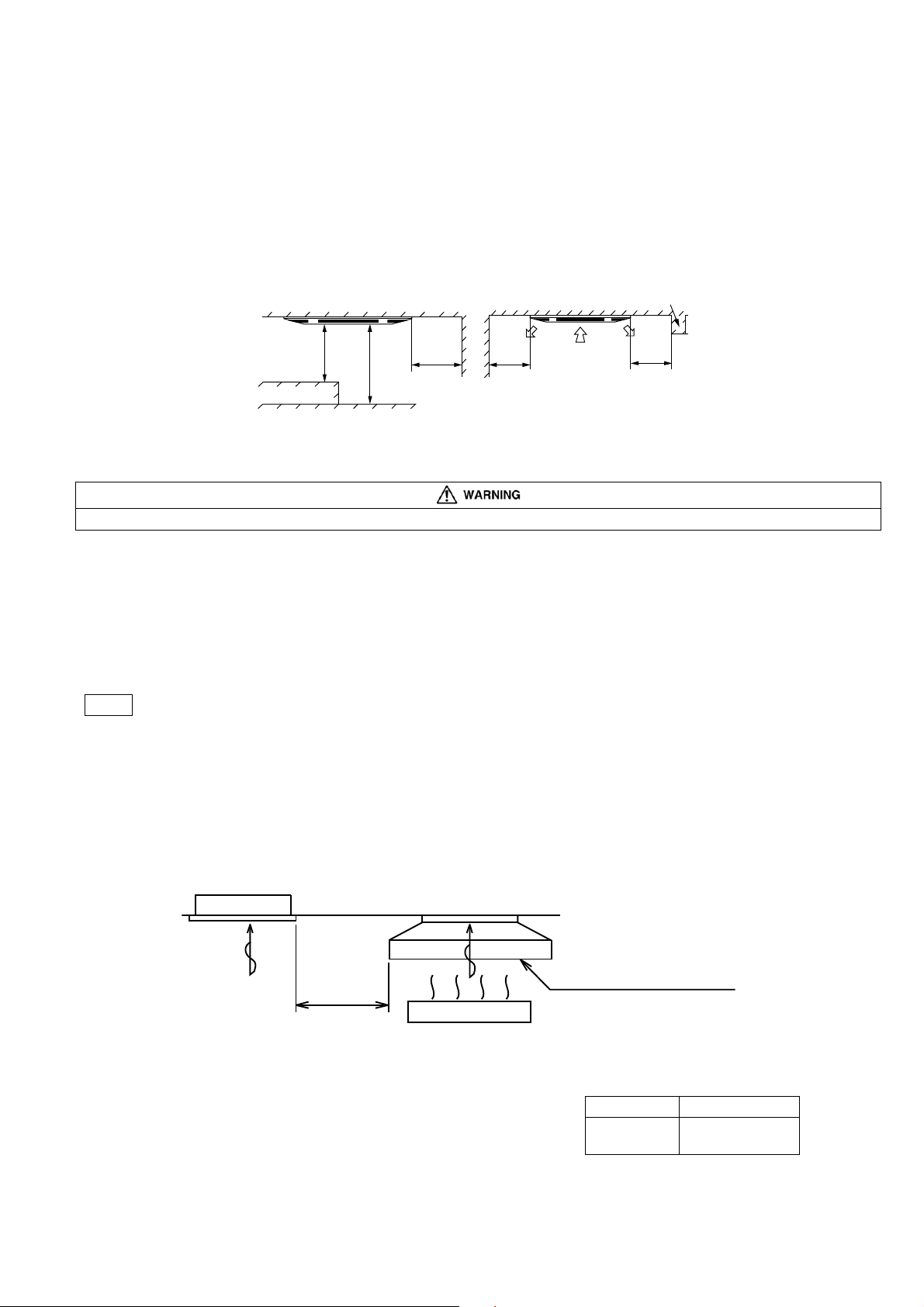
11. Installation Instruction
11.1 Indoor Unit
11.1.1 Selecting the Location for the Indoor Unit
Provide a check port on the piping side ceiling for repair and maintenance.
Install the indoor unit once the following conditions are satisfied and after receiving the customer approval.
1 The indoor unit must be within a maintenance space.
2 The indoor unit must be free from any obstacles in path of the air inlet and outlet, and must allow spreading
of air throughout the room.
3 Mount with the lowest moving parts at least 8 ft (2.4 m) above floor or grade level.
"
16
11
19
39
(1000)
(Unit: inch (mm))
or more
Obstacles
3
/8"
"
8
/
1
96"–118
(2400 – 3000)
Floor
(500) or
more
/16"
1911/16"
(500) or
more
11
19
(500) or
more
* If the height from the floor to ceiling exceeds three meters, air flow distribution deteriorates and the effect is
decreased.
4 The installation position must be able to support a load four times the indoor unit weight.
5 The indoor unit must be away from heat and steam sources, but avoid installing it near an entrance.
6 The indoor unit must allow easy draining.
7 The indoor unit must allow easy connection to the outdoor unit.
8 Place the indoor unit according to the height from the ceiling shown in the illustration below.
9 The indoor unit must be from at least 9.8 ft (3 m) away from any noise-generating equipment. The electrical
wiring must be shielded with a steel conduit.
10 If the power supply is subject to noise generation, add a suppressor.
11 Do not install the indoor unit in a laundry. Electric shocks may result.
Note
Thoroughly study the following installation locations
1 In such places as restaurants and kitchens, considerable amount of oil steam and flour adhere to the turbo
fan, the fin of the heat exchanger and the drain pump, resulting in heat exchange reduction, spraying,
dispersing of water drops, drain pump malfunction, etc.
In these cases, take the following actions:
o Make sure that the ventilation fan for smoke-collecting hood on a cooking table has sufficient capacity so
that it draws oily steam which should not flow into the suction of the air conditioner.
o Make enough distance from the cooking room to install the air conditioner in such place where it may not
suck in oily steam.
Air conditioner
/
13
/16"
11
(300) or less
(Unit: inch (mm))
Ensure ample
distance
2 Avoid installing the air conditioner in such
circumstances where cutting oil mist or iron
powder exist especially in factories, etc.
3 Avoid places where inflammable gas is
generated, flows-in, contaminated, or leaked.
4 Avoid places where sulphurous acid gas or
corrosive gas can be generated.
5 Avoid places near high frequency generators.
Cooking table
29
Use the ventilation fan for smokecollection hood with sufficient capacity.
collectionhoodwithsufficientcapacity.
Model Name Height in the ceiling
E12***
E18***
11" (280 mm) or
more
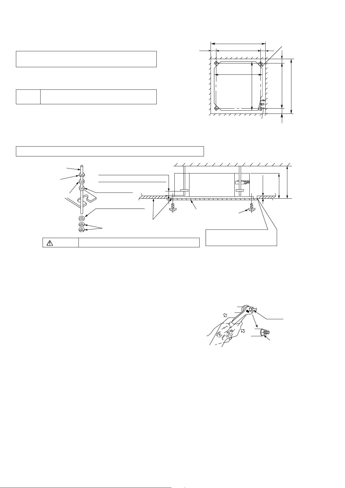
11.1.2 Installation of Indoor Unit
n
nch
H
andab
e
piping
This air conditioner uses a drain up motor.
Horizontally install the unit using a level gauge.
CEILING OPENING DIMENSIONS AND
BOLT LOCATION
The paper model for installation expand or shrink
according to temperature and humidity.
Check on dimensions before using it.
During the installation, care must be taken
Caution
not to damage electric wires.
The dimensions of the paper model for installation
are the same as those of the ceiling opening
dimensions.
Be sure to discuss the ceiling drilling work with the
workers concerned.
POSITIONS OF AIR CONDITIONER BODY AND CEILING SURFACE
angingbolt
(W3/8 or M10)
Nut
(W3/8 or M10)
M10Springwasher
Keep the length of the bolt from
the bracket to 1
Flat washer for M10
(accessory)
HANGING
9
/16" (40 mm)
Ceiling
259/16" (650) (Ceiling opening)
23/8"
(60)
(Hanging bolt)
2213/16" (580)
Air conditioner body
7
/8" (530)
20
(Unit size)
(U
" (580)
16
/
13
(Unit size)
22
Refrigerant pipe
"
16
/
7
4
(113 mm)
2
it: i
(60)
3
/8"
1
23/8"
(60)
7
"
8
/
11
" (530)
8
/
20
3
(282 mm)
(mm))
Drain pipe
(Hanging bolt)
" (650) (Ceiling opening)
16
/
9
25
"
8
/
(60)
" (292 mm)
2
/
1
11
ov
Flat washer for M10
Warning
(accessory)
Nut
(W3/8 or M10)
Adjust to the same height
Tighten the nut and bolt to prevent unit from falling
Paper model
for installation
Set screw for paper
model (4 pieces)
Open the ceiling board along the
outer edge of the paper model.
11.1.3 Refrigerant Piping
Refrigerant is charged to the outdoor unit. For details, see the manual for installation work of outdoor unit.
(Additional charging, etc.)
1 Brazing for piping.
a. Execute brazing before tightening the flare
nut.
b. Brazing must be executed while blowing
nitrogen gas. (This prevents generation of
oxidized scale in copper pipe.)
2 When there is a lot of brazings for long piping,
install a strainer midway of the piping. (The
strainer is locally supplied.)
3 Use clean copper pipe with inner wall surface
free from mist and dust. Blow nitrogen gas or
air to blow off dust in the pipe before
connection.
4 Form the piping according to its routing. Avoid
bending and bending back the same piping
point more than three times. (This will result in
hardening of the pipe).
5 After deforming the pipe, align centers of the
union fitting of the indoor unit and the piping,
and tighten them firmly with wrenches.
6 Connect pipe to the service valve or ball valve
which is located below the outdoor unit.
7 After completed the piping connection, be sure to check if there is gas leakage in indoor and outdoor
connection.
Union
Red mark
Con• rm the red mark of the union (thin side)
•
is always at lower direction after connecting
.
30
 Loading...